1
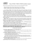
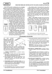
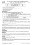
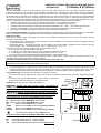
elmes electronic WIRELESS CONTROL SET FOR ROLLERS AND GATES ST100Hhet & ST200Hhet AUTOMATION The ST.. sets consist of 230VAC mains powered control unit with radio receiver and two 12V battery powered key-fob hand transmitters (ST100H) or two 9V battery hand transmitters (ST200H) and are designed for window rollers and gate automation. Both the transmitter (encoder) and the receiver (decoder) use the KEELOQ® code-hopping security system. The hand transmitters are provided with two different colour switches corresponding to up or down roller rotation. The control unit is programmable and has two 16A power relay outputs for connecting 230VAC tube motor and one relay output for warning/courtesy 230VAC lamp. Terminals are provided for connecting wired control wall switches and infrared barrier output. On board of the controller there is also LED for programming status indication. Following, are main ST100H and ST200H wireless control sets features: • wireless control with the use of one or two hand transmitter’s buttons – user selected by jumper JP1, • external warning/courtesy lamp (230VAC) operation mode control – user selected by jumper JP2, • automatic rolling door/shade closure after pre-programmed PAUSE time (1sec ÷ 4min) – user selected by jumper JP3, • automatic opening while in closing mode rotation on reset made by photo beam barrier protection (if fitted), • prolonging of the PAUSE time period on reset made by photo beam barrier protection. The ST100Hhet & ST200Hhet sets operate with all Elmes Electronic made key-fob and hand transmitters designed for 433,92MHz band. The ST200H set is factory supplied with two 200m operating range hand transmitters powered by 9V battery. Modes of operation Depending on selection made with jumper JP1 the set may be wireless controlled by the use of one or two buttons of hand transmitter as described below: • jumper JP1 shorted – operation control with two buttons of a hand transmitter: one for upwards rotation and stopping and next for downwards rotation and stopping. • jumper JP1 opened – operation control with only one button of a hand transmitter: sequential use of the button will start upwards rotation - stop – downwards rotation – stop – upwards rotation – stop … etc. Stopping of the tube motor rotation is achieved in one of the following ways: a) on any next use of hand transmitter or wall switch, b) on switching on of the motor’s end of line switch connected in series with the motor, c) on passing of the motor rotation time pre-programmed by the user (1s ÷ 4 min), d) on reset made by photo beam barrier obstacle detection (only on door/shade closing). On reset made by photo beam barrier obstacle detection while in closing mode, motor is stopped automatically and after one second pause the motor starts rotation in opening direction. Automatic rolling door/shade closure function on/off selection with jumper JP3: Warning! Activation of automatic closing function requires fitting of photo or infrared barrier protection beam securing obstacle free door/shade closing within movement range. • • on jumper JP3 shorted – automatic close function is set to OFF, on jumper JP3 opened – automatic close function is set to ON. With door/shade fully opened counting of PAUSE time period is started and after the pause has lapsed the automatic close function is activated. Reset made by photo beam barrier obstacle detection while in PAUSE mode prolongs the PAUSE time. Continued obstacle detection prohibits door closure. Lamp (230VAC type) connected to the control unit can operate in two ways: • as courtesy lamp (jumper JP2 shorted) – lights continuously at door/shade movement, also until end of programmed PAUSE time. MOTOR • as warning lamp (jumper JP2 opened) – pulses slowly at door/shade GROUND opening and PAUSE time and faster in door/shade closing. ST..H wire control terminals (NO ANY VOLTAGE ALLOWED!) COM - common wiring terminal, OP - wired wall switch terminal - opening rotation, CL - wired wall switch terminal – closing rotation, RS - reset photo/infrared barrier beam terminal. Must be wire CL RS wall switch: open, close LAMP CLOSE OPEN photo barrier NC type - courtesy/warning 230VAC lamp LIVE terminal. LED OP ⊗ PRG COM Description of ST..H control unit 230VAC wiring terminals: L - 230VAC mains supply LIVE wire terminal, N - 230VAC mains supply NEUTRAL wire terminal, PE - 230VAC mains supply GROUND wire terminal, PE - electric motor Ground wire terminal, OPEN - electric motor LIVE wire terminal (opening rotation), middle - electric motor Neutral wire terminal, CLOSE - electric motor LIVE wire terminal (closing rotation), TRANS. JP1 JP2 JP3 IMPORTANT! 230VAC supply LIVE wire must be connected to L terminal and NEUTRAL wire must be connected to N terminal. ~230V LIVE N L WARNING! Control unit and electric motor connection to 230VAC mains voltage require personal safety care procedures to be taken and mains voltage line be in off state at installation. M NEUTRAL PE PE Installation (as shown on the schematic diagram): shorted to COM terminal if barrier is not fitted. Installation hints The control units should be indoor installed with 230VAC wiring terminals in upwards direction and antenna wire let loose downwards (not glued or fitted to wall). Care should be taken not to expose the control unit to harsh environmental conditions such as very low/high temperatures or high humidity. The unit includes radio receiver thus any metal screening or interference with other electric/radio equipment operating in close distance should be avoided as may seriously shorten practical operating range of transmitter - receiver set. ST CONTROL UNIT PROGRAMMING PROCEDURES 1. Learning transmitter(s) to receiver's memory - max 12 (up to 112 on option): a) press control unit PRG switch for less than 2 seconds (PRG LED lights on). Releasing the switch LED continues to light indicating entering programming procedure, b) press any transmitter button twice - PRG LED switches off and starts blinking confirming end of the procedure. The transmitter is learned to the control unit memory. Number of transmitters in memory is limited to 12 (up to 112 on option), learning 13th will remove the first, learning 14th will remove second, etc. Removing one transmitter from control unit memory requires removing all transmitters and learning the remaining ones again. 2. Programming electric tube motor rotation time and PAUSE time: a) press control unit PRG switch for more than 2 and less than 8 seconds (PRG LED lights on). Releasing the switch PRG LED sets off. b) press on hand transmitter button or wired wall switch to start motor rotation (PRG LED lights on), c) when required motor rotation time has lapsed (max. 4 minutes) press the hand transmitter button or wired wall switch again - the electric motor stops and the courtesy/warning LAMP is sets to light on, d) after required PAUSE time has lapsed press transmitter button again – the lamp will set off and the PRG LED starts blinking several times confirming end of the procedure. 3. Deleting all transmitters from control unit memory: press receiver's PRG switch (PRG LED lights on) and hold for more than 8 seconds, until the receiver LED starts blinking confirming end of the procedure. The control unit memory is cleared. Important! 1. Procedure 2 above can be performed with the use of wired wall switch or transmitter learned to control unit memory. 2. Electric tube motor rotation time is factory set to approx. 4 seconds. Required rotation time should be programmed individually. Specification • mains supply 230VAC (2VA) control panel with superheterodyne receiver for 433,92MHz band, • relay outputs for motor control, 2 x NO, max 16A/250VAC, • courtesy/warning control relay output : max 5A/250VAC, • infrared obstacle detection barrier NC type (normally closed), • electric motor operation time (opening and closing) 1s ÷ 4 min, • programmable PAUSE time: 1s ÷ 4 min, • control panel external dimensions (l/w/h) 87/87/39mm, • open field maximal operating range: up to 100m for ST100H set and up to 200m for ST200H set. Manufacturer ELMES ELECTRONIC, 54-611 Wrocław – PL, ul. Avicenny 2, tel. (+4871) 784-59-61, fax 784-59-63 Manufacturer’s Limited Warranty: Elmes Electronic remote control sets carry one-year manufacturer’s warranty as from date of purchase. The warranty is limited to the replacement of faulty original parts or repair defects of improper manufacture. Damage, faulty use or improper handling by the user or installer as well as any changes in product’s hardware or software caused by the user violets the warranty and all due repair costs will be charged. Elmes Electronic shall not be responsible for any damage human or material caused by its products failure to operate correctly. Elmes Electronic reserves the right to change product specification without prior notice. KEELOQ® is a registered trademark of Microchip Technology Inc., USA. e-mail: [email protected] internet: www.elmes.pl Elmes Elektronik 2007. All rights reserved.