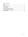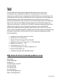
1
Ecopia HMS-5300 (80 – 350K) Hall Effect User Manual v1.0 Woodall Research Group, Ghausi 1123 Kyle Montgomery, PhD kmontgomery.net 7/2/2013 Table of Contents Specs .................................................................................................................................................. 2 Mfg Point of Contact .................................................................................................................. 2 Sample Loading............................................................................................................................ 3 Room Temperature Measurement...................................................................................... 5 Variable Temperature Measurement ................................................................................ 8 System Shutdown .....................................................................................................................10 Page 1 of 10 Specs The HMS-5000, HMS-5300, and HMS-5500 Hall Effect Measurement Systems plot concentration versus temperature, mobility versus temperature, resistivity versus temperature, conductivity versus temperature, and Hall coefficient versus temperature. The system provides the test results as tabular data as well as in graph form. The user defines the desired temperature steps within the temperature range, fills the two LN2 reservoirs if performing sub ambient testing, and then the system automatically applies and switches the input current, measures the voltages, changes temperature, and moves the magnets all without user intervention. Once the test is finished, the temperature dependent graphs and tabular data are ready for viewing. The magnet movement is motor controlled and automated, variable temperature capability, and powerful analysis software. The systems ramp to each user defined temperature, stabilize, makes the measurement (including moving the magnet automatically), and then plots the various temperature dependent material electrical properties. Sample size: 5 mm x 5mm up to 15m x 15mm Resistivity: 10-4 to 107 (Ohms-cm) Magnet : Permanent magnet, 30 mm diameter Magnet Flux Density: 0.55T nominal +/-1% of marked value Mobility: (cm2/Volt-sec) 1 ~ 107 Concentration: (cm-3): 107 ~ 1021 Current Source: Range: 1nA-20mA Compliance: 12V Minimum Hall Voltage: 1μV Temperature Ranges: HMS-5300: 80K to 350K Mfg Point of Contact (should problems arise) Larry Bridge Bridge Technology PO Box 9275 Chandler Heights, AZ 85227 Tel: 480-988-2256 Cell: 480-242-6703 Fax: 480-452-0172 Email: [email protected] Web: www.bridgetec.com Page 2 of 10 Sample Loading WEAR GLOVES FOR THIS PROCEDURE SAMPLE SIZE: 5mm x 5mm up to 15mm x 15mm 1. Ensure the control unit is powered on by checking for green light on front panel. If not turned on, flip the switch on the back left side of the unit. 2. Remove the sample holder by gently lifting up on the magnet lid until it releases from the main unit. 3. With cables in-tact, position the sample holder on the stand, with the sample board facing probe-side up. 4. Place sample onto center of sample board. 5. Place probes onto sample contacts by pushing down on the back side of the probes. 6. Remove sample holder from stand and position the sample board into the cold zone on the main unit. 7. Initially align and fit the front side of the sample holder with the body of the main unit, then gently push down the sides and the back of the sample holder so it becomes flush with the main unit all the way around. a. NOTE: this is a little tricky since it is a tight fit, but if you follow the procedure of setting the front side first you should be fine. Just be sure that all sides are eventually fully pushed down. Page 3 of 10 Page 4 of 10 Room Temperature Measurement 1. Fill out the Excel spreadsheet on the desktop logging your time on the system. 2. Launch the software “HMS-5300 Ver5.8.0.7”. 3. Complete the “Input Value” box accordingly: a. Date: automatically set b. UserName: your choice c. ComPort: should always be COM3 d. SampleName: your choice e. Temp.: initially just test at ROOM TEMP. f. TempDelay: delay time before measurement starts at the given set point g. Initial & Final: not used for room temp measurement h. Step: number of measurements to take (spread evenly between initial/final temperatures). The software can accommodate up to 99 different test steps. i. B: the preset fixed magnetic field strength (0.556 T for this system) j. D: your film thickness in um k. I: source current for testing. This can range from 1nA to 20mA. High resistivity (low conductivity) samples should use lower test current, while low resistivity (high conductivity) samples should use higher test current (on the order of 1015mA). 4. Click the “OPENPORT” button at bottom left to check the connection status. You should see “connection success” in the “Operating Description” box. If not, restart the program, or try changing the ComPort. 5. Click the “MEASURE” button to begin measurements. You will see the “Operating Description” box begin to cycle through the various steps for each measurement. 6. Results: in the “Measurement Data” box, the first row of boxes indicates forward current being applied, while the second row indicates reverse current being applied. Page 5 of 10 a. NOTE: you should check for ohmic contact by comparing the forward and reverse biased measurements. The absolute values from each row should closely correlate (probably within ~5%). 7. The “Result” box summarizes the primary calculated parameters and the “Result Data” just tabulates the data as a function of temperature and current. a. NOTE: a negative value for Bulk Concentration and Hall Coefficient indicates majority carrier electrons, while a positive value indicates majority carrier holes. 8. Click the “SAVE” button to save your data (the file will have a “.hall” extension, but can be opened in notepad or Excel). 9. To reload previously saved data, click the “LOAD” button. 10. If you need to correct for a different thickness, D, or magnet field strength, B, you can reload saved data and then click the “CALCUL” button after putting in the correct values in the “Input Value” box. Page 6 of 10 ADDITIONAL OPTION: 1. To do a standard I-V sweep, click the “GoTo IV Curve” button on bottom right. 2. You will mainly need to set the initial and final current values that you want to sweep, and then click “MEASURE.” a. According to the mfg guide, the “CONT. REF %” is the ratio between horizontal and vertical resistance values. So, if the vertical resistance is 10ohm and the horizontal resistance is 20ohm, the value of “CONT.REF%” is 200%. The system will give a “contact fail” message is “CONT.REF%” is over 1000%. 3. You can alternatively do a sweep of current vs. resistance (I-R). Page 7 of 10 Variable Temperature Measurement WEAR CRYO GLOVES AND PROTECTIVE EYEWEAR FOR THIS PROCEDURE 1. Fill out the Excel spreadsheet on the desktop logging your time on the system. 2. For variable temperature measurements, you will need to use liquid nitrogen. A 5L dewar is provided in the lab, which can be refilled in the AMCaT lab in Kemper. 3. After loading your sample, use the small 1L dewar to pour LN2 into the internal reservoir using the funnel in the hole on the left side of the cover. 4. Then, fill the LN2 tank sufficiently with LN2 and put the vented cover back on. a. To get down to 80K, you will likely need to refill both reservoirs 2-3 times as the LN2 boils off. b. You should also wait at least 5 minutes for the temperature to equilibrate before starting measurements. 5. Complete the “Input Value” box accordingly: a. Date: automatically set b. UserName: your choice c. ComPort: should always be COM3 d. SampleName: your choice e. Temp.: set to VARIABLE f. TempDelay: delay time before measurement starts at the given set point g. Initial & Final: initial and final temperatures h. Step: number of measurements to take (spread evenly between initial/final temperatures). The software can accommodate up to 99 different test steps. i. B: the preset fixed magnetic field strength (0.556 T for this system) j. D: your film thickness in um k. I: source current for testing. This can range from 1nA to 20mA. High resistivity (low conductivity) samples should use lower test current, while low resistivity (high conductivity) samples should use higher test current (on the order of 1015mA). 6. On the software, fill in your desired temperature range and number of steps in the “Input Value” box. The software can accommodate up to 99 different test steps. 7. Click the “OPENPORT” button at bottom left to check the connection status. This will also activate the temperature measurement, which will update the sample temperature continuously. 8. After the temperature has reached the lowest desired temperature, click the “MEASURE” button to commence measuring. The system will modulate the heater to ramp the temperature back up to desired set points. Page 8 of 10 9. Wait for all measurements to complete before doing anything else. 10. To visualize the data, you can use the “GoTo TempChar” to see various plots vs. temperature. 11. After you complete your measurement, set up an additional test with start and stop of 330 K, in 3 steps and run. This will serve to dry out the sample board prior to exposing to the room. 12. Prior to removing the sample, wipe down the exterior to remove the moisture. And, be sure there is no more LN2 in the reservoir tank. Page 9 of 10 System Shutdown 1. On the software, click “STOP” and then “CLOSE”. Do NOT just click the “x” close button in upper right. 2. Remove sample per the sample loading procedure (remember to wear gloves). If the exterior is damp, please wipe this down prior to removing from main unit. 3. Re-insert the sample holder in the main unit (carefully). 4. Turn off main control unit by flipping switch on the back left side. 5. Note your “Time Out” and any comments regarding your measurements in the Excel spreadsheet. Page 10 of 10