1
VNX Unified Storage
Implementation Lab Guide
August 2011
EMC Education Service
Copyright
Copyright © 1996, 2000, 2001, 2002, 2003, 2004, 2005, 2006, 2007, 2008, 2009, 2010., 2011 EMC
Corporation. All Rights Reserved. EMC believes the information in this publication is accurate as of its
publication date. The information is subject to change without notice.
THE INFORMATION IN THIS PUBLICATION IS PROVIDED “AS IS.” EMC CORPORATION MAKES NO
REPRESENTATIONS OR WARRANTIES OF ANY KIND WITH RESPECT TO THE INFORMATION IN THIS
PUBLICATION, AND SPECIFICALLY DISCLAIMS IMPLIED WARRANTIES OF MERCHANTABILITY OR FITNESS
FOR A PARTICULAR PURPOSE.
Use, copying, and distribution of any EMC software described in this publication requires an applicable
software license.
EMC2, EMC, Data Domain, RSA, EMC Centera, EMC ControlCenter, EMC LifeLine, EMC OnCourse, EMC
Proven, EMC Snap, EMC SourceOne, EMC Storage Administrator, Acartus, Access Logix, AdvantEdge,
AlphaStor, ApplicationXtender, ArchiveXtender, Atmos, Authentica, Authentic Problems, Automated
Resource Manager, AutoStart, AutoSwap, AVALONidm, Avamar, Captiva, Catalog Solution, C-Clip,
Celerra, Celerra Replicator, Centera, CenterStage, CentraStar, ClaimPack, ClaimsEditor, CLARiiON,
ClientPak, Codebook Correlation Technology, Common Information Model, Configuration Intelligence,
Configuresoft, Connectrix, CopyCross, CopyPoint, Dantz, DatabaseXtender, Direct Matrix Architecture,
DiskXtender, DiskXtender 2000, Document Sciences, Documentum, elnput, E-Lab, EmailXaminer,
EmailXtender, Enginuity, eRoom, Event Explorer, FarPoint, FirstPass, FLARE, FormWare, Geosynchrony,
Global File Virtualization, Graphic Visualization, Greenplum, HighRoad, HomeBase, InfoMover,
Infoscape, Infra, InputAccel, InputAccel Express, Invista, Ionix, ISIS, Max Retriever, MediaStor,
MirrorView, Navisphere, NetWorker, nLayers, OnAlert, OpenScale, PixTools, Powerlink, PowerPath,
PowerSnap, QuickScan, Rainfinity, RepliCare, RepliStor, ResourcePak, Retrospect, RSA, the RSA logo,
SafeLine, SAN Advisor, SAN Copy, SAN Manager, Smarts, SnapImage, SnapSure, SnapView, SRDF,
StorageScope, SupportMate, SymmAPI, SymmEnabler, Symmetrix, Symmetrix DMX, Symmetrix VMAX,
TimeFinder, UltraFlex, UltraPoint, UltraScale, Unisphere, VMAX, Vblock, Viewlets, Virtual Matrix, Virtual
Matrix Architecture, Virtual Provisioning, VisualSAN, VisualSRM, Voyence, VPLEX, VSAM-Assist,
WebXtender, xPression, xPresso, YottaYotta, the EMC logo, and where information lives, are registered
trademarks or trademarks of EMC Corporation in the United States and other countries.
All other trademarks used herein are the property of their respective owners.
© Copyright 2011 EMC Corporation. All rights reserved. Published in the USA.
Revision Date: May 6, 2011
Revision Number: MR-7CP-VNXUNIIMP.1.0
Document Revision History
Rev #
1.0
3
File Name
VNX Unified Storage Implementation
Lab Guide
Date
07/2011
4
Table of Contents
COPYRIGHT............................................................................................................. 2
DOCUMENT REVISION HISTORY ............................................................................. 3
PRE-LAB EXERCISES INTRODUCTION ....................................................................... 8
LAB EXERCISE 1: IMPLEMENTING UNISPHERE SECURITY ......................................... 9
LAB 1: PART 1 – VERIFY DOMAIN SECURITY AND DEFINE A GLOBAL USER ACCOUNT ...............10
LAB EXERCISE 2: VNX SYSTEM CONFIGURATION .................................................... 17
LAB 2: PART 1 – CONFIGURE VNX SP MEMORY ..............................................................18
LAB 2: PART 2 – CONFIGURE SP CACHE SETTINGS ............................................................21
LAB 2: PART 3 – VERIFY SP NETWORK CONFIGURATION ....................................................23
LAB EXERCISE 3: STORAGE CONFIGURATION ....................................................... 25
LAB 3:
LAB 3:
LAB 3:
LAB 3:
PART 1 – PROVISIONING STORAGE FOR VNX FILE ...................................................26
PART 2 – CREATE POOLS AND RAID GROUPS ........................................................30
PART 3 – CREATE TRADITIONAL LUNS ..................................................................32
PART 4 – CREATE THICK AND THIN LUNS ..............................................................34
LAB EXERCISE 4: CONFIGURING HOST ACCESS TO VNX LUNS - WINDOWS ............ 37
LAB 4: PART 1 – INSTALLING HBA DRIVERS - WINDOWS ...................................................39
LAB 4: PART 2 – INSTALLING POWERPATH ......................................................................46
LAB 4: PART 3 – INSTALLING THE UNISPHERE AGENT.........................................................52
LAB 4: PART 4 – INSTALLING NAVISPHERE SECURE CLI ......................................................54
LAB 4: PART 5 – VERIFYING THE VNX ARRAY IS CONFIGURED TO AUTO-MANAGE HOSTS ........57
LAB 4: PART 6 – CREATE AND POPULATE STORAGE GROUPS WITH EMC UNISPHERE - WINDOWS 59
LAB 4: PART 7 – CONFIGURE WINDOWS HOST ACCESS TO LUNS ........................................61
LAB 4: PART 8 – REMOVE THE WINDOWS HOST FROM ITS STORAGE GROUP IN PREPARTION FOR
THE LINUX LABS ..........................................................................................................64
LAB EXERCISE 5: CONFIGURING HOST ACCESS TO VNX LUNS - LINUX ................... 67
LAB 5: PART 1 - INSTALLING EMULEX DRIVERS ON A LINUX HOST ..........................................69
LAB 5: PART 2 - INSTALLING POWERPATH SOFTWARE ON A LINUX HOST ...............................80
LAB 5: PART 3 - INSTALL THE UNISPHERE AGENT & NAVISPHERE SECURE CLI SOFTWARE ON YOUR
LINUX HOST................................................................................................................84
LAB 5: PART 4 - CREATE AND POPULATE STORAGE GROUPS WITH EMC UNISPHERE – LINUX.....90
LAB 5: PART 5 - CONFIGURE LINUX HOST ACCESS TO LUNS ................................................93
LAB 5: PART 6 - REMOVE THE THE LINUX HOST FROM THE STORAGE GROUP IN PREPARTION TO
WORK WITH WINDOWS AGAIN .................................................................................... 103
LAB 5: PART 6 ADDENDUM – PARTITION LINUX DEVICES THROUGH THE COMMAND LINE
INTERFACE .............................................................................................................. 106
LAB 5: PART 7 – VNX ISCSI PORT CONFIGURATION INFORMATION CONFIRMATION ............. 108
LAB 5: PART 8 – CREATE AND POPULATE STORAGE GROUPS FOR WINDOWS & LINUX ISCSI HOSTS
109
5
LAB EXERCISE 6: ADVANCED STORAGE POOL LUN OPERATIONS......................... 113
LAB 6: PART 1 – EXPANDING POOL LUNS .................................................................... 114
LAB 6: PART 2 – EXPANDING RAID GROUP LUNS ......................................................... 117
LAB EXERCISE 7: NETWORK AND FILE SYSTEM CONFIGURATION ........................ 121
LAB 7: PART 1 – CONFIGURE NETWORKING ON VNX ..................................................... 122
LAB 7: PART 2 – CONFIGURE AND MANAGE FILE SYSTEMS FOR VNX................................. 126
LAB EXERCISE 8: NFS FILE SYSTEM EXPORT AND PERMISSIONS .......................... 131
LAB 8: PART 1 – EXPORTING FILE SYSTEMS FOR NFS CLIENTS .......................................... 132
LAB 8: PART 2 – ASSIGNING ROOT PRIVILEGES.............................................................. 138
LAB EXERCISE 9: CIFS IMPLEMENTATION ............................................................ 145
LAB 9:
LAB 9:
LAB 9:
LAB 9:
PART 1 – PREPARING THE SYSTEM FOR CIFS ....................................................... 146
PART 2 – CREATE AND JOIN A CIFS SERVER ........................................................ 151
PART 3 – CREATE A CIFS SHARE ....................................................................... 154
PART 4 – DELETING A CIFS SERVER ................................................................... 164
LAB EXERCISE 10: IMPLEMENTING FILE SYSTEM QUOTAS ................................... 167
LAB 10: PART 1 – CONFIGURING QUOTAS USING THE WINDOWS & UNISPHERE .................. 168
LAB 10: PART 2 – VIEW QUOTA REPORTS FROM A LINUX CLIENT ..................................... 180
LAB EXERCISE 11: CIFS FEATURES ....................................................................... 183
LAB 11: PART 1 - CONFIGURE A CIFS AUDIT POLICY ...................................................... 184
LAB 11: PART 2 - CONFIGURING CIFS FOR HOME DIRECTORIES ....................................... 188
LAB EXERCISE 12: NETWORKING FEATURES ........................................................ 191
LAB 12: PART 1 – CONFIGURING LACP ....................................................................... 192
LAB 12: PART 2 – CONFIGURE AN FSN DEVICE ............................................................. 197
LAB 13: CREATE AN EVENT MONITOR TEMPLATE ............................................... 201
LAB 13: PART 1 – CONFIGURING A CENTRALIZED MONITOR USING THE CONFIGURATION WIZARD202
LAB EXERCISE 14: SNAPVIEW SNAPSHOTS ......................................................... 205
LAB 14: PART 1 – ALLOCATE LUNS TO THE RESERVED LUN POOL WITH EMC UNISPHERE .... 207
LAB 14: PART 2 - CREATE A SNAPVIEW SNAPSHOT WITH EMC UNISPHERE ON WINDOWS .... 209
LAB 14: PART 3 - TEST PERSISTENCE OF A SNAPVIEW SESSION ......................................... 213
LAB 14: PART 4 - TEST THE SNAPVIEW ROLLBACK FEATURE WITH EMC UNISPHERE ............ 214
LAB 14: PART 5 - START AND TEST A CONSISTENT SNAPVIEW SESSION WITH EMC UNISPHERE216
LAB 14: PART 6 - TEST THE OPERATION OF THE RESERVED LUN POOL WITH EMC UNISPHERE ON
WINDOWS .............................................................................................................. 217
LAB EXERCISE 15: SNAPVIEW CLONE .................................................................. 221
LAB 15: PART 1 – ALLOCATE CLONE PRIVATE LUNS AND ENABLE PROTECTED RESTORE ....... 222
LAB 15: PART 2 – CREATE AND TEST A CLONE USING EMC UNISPHERE ............................. 223
LAB 15: PART 3 – PERFORM A CLONE CONSISTENT FRACTURE ......................................... 226
6
LAB EXERCISE 16: VNX SNAPSURE ...................................................................... 227
LAB 16:
LAB 16:
LAB 16:
LAB 16:
PART 1 – CONFIGURING SNAPSURE................................................................. 228
PART 2 – RESTORE AND REFRESH SNAPSHOTS WITH NFS .................................... 232
PART 3 – RESTORE AND REFRESH SNAPSHOTS WITH CIFS .................................... 237
PART 4 – CONFIGURING WRITEABLE SNAPSHOTS WITH CIFS ............................... 240
APPENDIX A: HURRICANE MARINE, LTD ............................................................. 243
APPENDIX A: HURRICANE MARINE, LTD – CONT. ................................................ 244
APPENDIX B: HURRICANE MARINE DOMAIN ENVIRONMENTS ........................... 245
APPENDIX C: WINDOWS USER AND GROUP MEMBERSHIPS ............................... 246
APPENDIX D: LINUX USERS AND GROUPS ........................................................... 247
APPENDIX F: TEAM – IP ADDRESSES SUMMARY ................................................. 249
7
Pre-Lab Exercises Introduction
Important
The following lab exercises provide the steps for setting up Windows and
Linux to interact with the VNX-series storage system through Block and
File connectivity.
A few important notes!
Note 1: You will be required throughout the lab to work on Physical
Hosts as well as VMs (Virtual Machines). Please read through the purpose
section of each lab to verify what host and setup you should be working
with prior to starting the lab. If there is any confusion prior to starting the
labs then please contact the instructor and work out any issues you may
be having with them.
Note 2: Not all screen captures were made on the lab equipment you
will be using and therefore may differ slightly from what you will see.
Read each lab and step completely before attempting it; do not simply
follow the pictures!
Note 3: The names of the files used to install the VNX software may
differ slightly from one revision to the next. As an example, the Unisphere
Server Utility software for this OE revision is presented with the following
naming convention:
UnisphereServerUtil-Win-32-x86-en_US-1.1.0.1.0366-1.exe
Note 4: All hardware and software assignments per team are listed in
the Appendix F of this student guide.
Note 5: Not all physical lab setups are put together in the same way.
Please understand the setup you may be working on may differ slightly
from the one we are describing in the labs. Contact the instructor if you
are confused on any of the steps during the duration of the course.
8
Lab Exercise 1: Implementing Unisphere Security
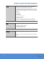
Purpose:
These lab exercises provide the steps for setting up a Windows based
management station and using the management station to configure the
required hardware and software on a VNX-series storage system.
Synopsis:
You have just implemented a successful installation of a VNX array for
your customer. The VNX Installation Assistant (VIA) has already been run
on the systems you will be working and they have already been set up
with prerequisite software and enablers. The hosts, however, will need to
be setup and have all necessary software installed since they are without
it presently.
Hurricane Marine, LTD hired a new member for the Storage
Administration Team. Tim Taler (username: Ttaler) is not yet a part of the
Company’s Microsoft AD. He has some experience with VNX Snapshots for
File. (We will cover Snapshots later in this course.)
The head of the IT department, would like to give Tim administrative
privileges to manage file system snapshots.
Tasks:
In this lab exercise, you will perform the following tasks:
9
Configure and Verify Domain Security
Create a Global User account on the VNX
Create a local Group on the VNX
Define a new Role
Lab 1: Part 1 – Verify Domain Security and Define a Global User Account
Step
1
Action
System Login:
2
Verify Domain Security:
10
Login to your team’s VM Windows host named Win-X where X is your team number
(refer to your team’s Appendix). The username will be Administrator and the password
will be adXmin where X is the subnet address provided by the instructor.
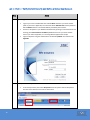
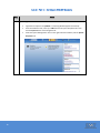
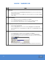
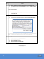
Connect to Unisphere in your Windows workstation by opening an Internet browser and
entering your Control Station’s IP address (VNX#cs0 where # is your team number refer to your team’s Appendix). If a Licensing Window appears click Accept.
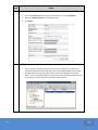
Login to Unisphere using the credentials for the default sysadmin user located in the
Appendix.
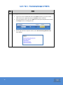
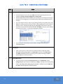
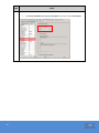
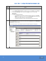
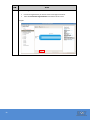
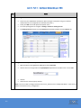
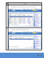
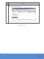
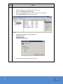
If not already selected, then select All Systems from the systems selector drop-down.
The click on the Domains menu item as shown here.
Step
3
Action
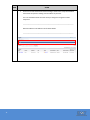
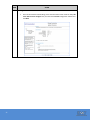
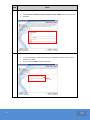
Choose Local under the Domains’ Name heading as shown here. Verify the IP Address
listed under the System’s heading is the IP Address of your SP-A.
If it is not the Master Node then how could you change that assignment within
Unisphere?
_____________________________________________________________________
Which IP Addresses can fulfill the role of Master Node?
_____________________________________________________________________
11
Step
3
Action
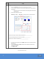
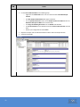
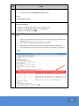
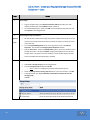
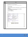
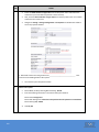
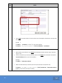
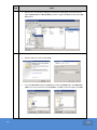
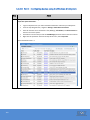
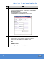
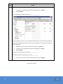
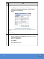
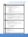
Create a user-defined Role:
In this step, you will create a new administrative role on the system for managing
SnapSure. This will first require the SnapSure license to be enabled. In the All Systems
drop-down, select your VNX, then on the top menu bar click on the Settings button.
From the right-side Tasks pane in the More Setting section, select Manage License for
File. Check the SnapSure Licensed: option and click OK. To prepare for additional labs,
also enable the licenses for any unchecked licenses by checking a license one at a time
and selecting OK. This may take a short amount of time, please be patient!
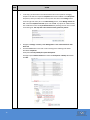
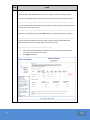
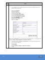
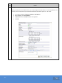
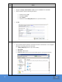
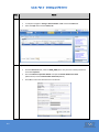
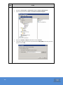
Navigate to Settings > Security > User Management > User Customization for File >
Roles tab.
Click the Create button and create a role according to the following information:
Role Name: Snapshots
Description: Can only modify file system checkpoints.
Privileges: Expand Data Protection and select the Checkpoints - Modify radio button.
Click OK.
12
Step
3
Action
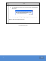
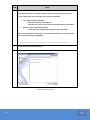
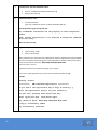
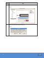
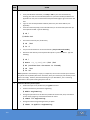
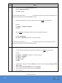
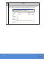
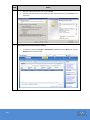
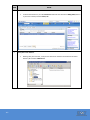
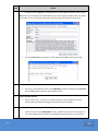
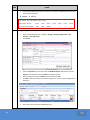
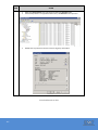
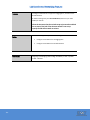
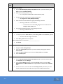
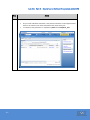
Verify Role configuration:
The snapshots role should appear under the Roles tab in User Customization for File window.
4
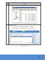
Create a local Group:
13
Navigate to Settings > Security > User Management > User Customization for File >
Groups tab.
Click the Create button and create a group according to the following information:
Group Name: Snapshots
GID: Auto select
Role: Snapshots
Group Type: Local only Group
Click OK
Step
5
Action
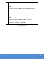
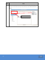
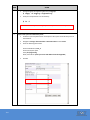
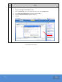
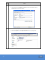
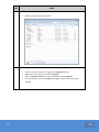
Verify Group configuration:
The Snapshots group should appear under the Groups tab in User Customization for File window.
6
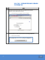
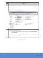
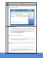
Create a Global user account:
14
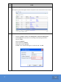
Navigate to Settings > Security > User Management > Global User Management.
Click the Add button and create a user according to the following information:
Username: Ttaler
Password: sysadmin1
Confirm Password: sysadmin1
Storage Domain Role: Operator
Click Ok. At the “add the following user” window click Yes. Click OK.
Step
7
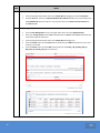
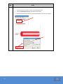
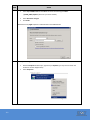
Action
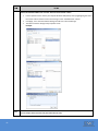
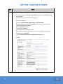
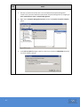
Add user Ttaler to the Snapshots Group:
15
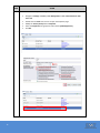
Navigate to Settings > Security > User Management > User Customization for File >
Users tab.
Double-click the Ttaler user account to open the Properties page.
Modify the Primary Group field to Snapshots.
Select the Snapshots local group/role and uncheck opadmin(Operator).
Click OK.
Step
8
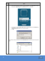
Action
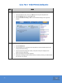
Verify Ttaler authentication:
Logout from Unisphere and log back in with the new Global user Ttaler (case sensitive)
credentials.
Verify that the new local user account is able to login and does not have creation and
modify rights on e.g. network operations like DNS or Routing. From the Dashboard
view, select your VNX from the All System dropdown lists. Navigate to Settings >
Network > Settings for File.
All buttons should appear grayed out. The account is also not able to modify any
administrative account. Since there is no file system snapshots implemented yet, you
can not verify all of access rights for the new local user at this time.
Close Unisphere.
End of Lab Exercise 1
16
Lab Exercise 2: VNX System Configuration
17
Purpose:
A new VNX Unified storage system has been deployed. You must now
configure and verify the VNX storage system SP (Storage Processor)
memory and cache settings for optimal performance.
Tasks:
In this lab exercise, you will perform the following tasks:
Enable and disable read and write cache
Configure VNX SP memory for read and write caching
Configure write cache watermarks
Verify SP network configuration
Lab 2: Part 1 – Configure VNX SP Memory
Step
1
Action
System Login:
18
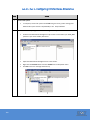
Login back to Unisphere as sysadmin. If a Licensing Window appears click Accept.
From the Dashboard view, select your VNX from the All System dropdown lists. Then
click the System button on the Navigation bar.
Under the System Management menu on the right side of the window, click the System
Properties link.
Step
2
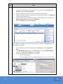
Action
Disable Read and Write Cache:
Click the SP Cache tab.
If SPA and SPB read cache and/or write cache are enabled, disable them by clicking on
the check box for each setting (this removes the check marks).
o If SPA and SPB read cache are grayed out, disable write cache only.
Click Apply, Yes, Yes, OK.
Note: If an SP is removed you cannot use Unisphere to set the write cache .
19
Step
3
Action
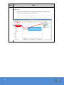
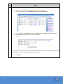
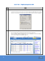
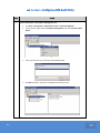
Configure SP Memory:
Click on the SP Memory tab and note the Total Memory for each SP.
Use the slide bar to experiment with the SPA and SPB Read Cache values and Write
Cache values.
o Note that you can only raise Read Cache after lowering Write Cache from its
maximum value.
Set the values as follows for each SP:
Read Cache = 200MB
Write cache = remaining amount or maximum allowed
1. How much memory was left for Write Cache Memory? __________________
2. Can all remaining memory be used for write cache? ________________
3. What value is shown for Total Memory? ___________________
Reconfigure both SPs Read cache to 512MB and Write cache to remainder and click
Apply, Yes, OK.
Click the SP Cache tab and Enable the Write cache and both SP’s Read cache by
selecting each checkbox.
Click Apply, Yes, OK.
End of Lab Exercise 2 Part 1
20
Lab 2: Part 2 – Configure SP Cache Settings
Step
1
Action
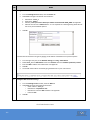
Verify Cache page size:
Click the SP Cache tab.
Under Configuration, select a page size of 8KB using the drop-down lists.
In cases where I/O size is very stable, it is beneficial to set the cache page size to the request size
seen by the storage system, the file-system block size or, if raw partitions are used, the
application block size. In environments with varying I/O sizes, the 8KB page size is optimal.
2
Configure Watermarks:
21
From the SP Cache tab, verify the Enable Watermarks checkbox is checked.
Set the Low Watermark to 50% by clicking the up or down arrow of the spin button
control as needed.
Set the High Watermark to 70% by clicking the up or down arrow of the spin button
control as needed.
Click Apply, Yes, OK.
Step
Action
Uncheck the Enable Watermarks box. Note the changes.
When the Watermarks are disabled, what values do the High and Low Watermarks revert to?
_________________________
Check the Enable Watermarks box.
Change the watermarks back to 70% for Low and 90% for High.
Click Apply, Yes, OK.
Close the Systems Properties window.
Note: The Mirrored Write Cache box is grayed-out and cannot be changed. The HA Vault box is
also grayed-out. This option determines the availability of write caching when a single drive in
the cache vault fails.
End of Lab Exercise 2 Part 2
22
Lab 2: Part 3 – Verify SP Network Configuration
Step
1
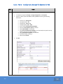
Action
Access SP network settings:
2
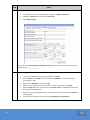
Verify SP network configuration:
23
From the Dashboard view, select your VNX from the All System dropdown lists.
Click the Settings button on the Navigation bar.
Click the Edit Network Settings - SPA link under Network Settings on the right side
window
Click the Network tab.
From Management Port Settings use the dropdown to view the available options and
verify the Link Status setting.
From the Virtual Port Properties window, verify that virtual port 0 displays the IP
address of SPA (see Appendix).
Click on Virtual Port 0 and select Properties.
Verify that the settings for SPA’s Network Name, IP Address, Gateway, and Subnet Mask
are correct for your system.
Step
Action
Click Cancel, and close Unisphere.
End of Lab Exercise 2
24
Lab Exercise 3: Storage Configuration
25
Purpose:
In this lab, you will provision storage for a VNX Unified system in
preparation for configuring file systems and attaching block hosts.
Tasks:
In this lab exercise, you will perform the following tasks:
Provision storage for a VNX for File platform
Create Pools and RAID Groups
Create traditional LUNs
Create Thin LUNs and Thick LUNs
Lab 3: Part 1 – Provisioning Storage for VNX File
Step
1
Action
System Login:
26
Login to your team’s VM Windows host named Win-X where X is your team number
(refer to your team’s Appendix) with your sysadmin account credential.
From the Dashboard view, select your VNX from the All System dropdown lists and click
the Storage button on the Navigation Bar.
On the right side of the Unisphere window, select Disk Provisioning Wizard for File,
under Wizards.
Step
2
Action
Running the wizard:
27
Once the wizard has finished loading, review the information listed. Check the “Yes, this
is the VNX I want to configure” box, and choose the Custom configuration method and
click Next.
Step
3
Action
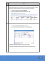
Checking for Understanding:
1. Reserve twenty 300 GB SAS drives for future use. Capacity mode is checked by default.
2. Look at the Available Pools for File area. What is the Pool Name given for Capacity Mode?
_____________________________________________________________________________
3. Uncheck Capacity Mode and check Protection Mode for both drive types. Which RAID type is
this mode (hint: look at pool name)?
______________________________________________________________________________
4. What is the available pool name when both Capacity and Protection Mode are selected?
______________________________________________________________________________
5. Check Performance Mode for both drive types and then uncheck Capacity Mode and
Protection Mode for both drive types. What is the pool name here?
_______________________________________________
28
Leave Performance Mode selected. Make sure you have twenty 300 GB SAS drives
reserved for future use and 1 hot spare.
Click Apply to continue.
Step
4
Action
Verification:
After clicking Apply in the previous step, an information window should appear. Click
Yes to continue.
When the wizard is complete, click Finish to exit out of the wizard.
In Unisphere, navigate to Storage > Storage Configuration > Storage Pools for File.
What is the name of the Storage Pool listed there?
_____________________________________________
End of Lab Exercise 3 Part 1
29
Lab 3: Part 2 – Create Pools and RAID Groups
Step
1
Action
Create Pool 0:
2
Using a similar process, create Pool 1 by manually selecting the following 4 disks
0_0_10, 0_0_11, 0_0_12, 0_0_13. In the RAID Type: drop-down select RAID 1/0 and
click Apply. Click Yes to proceed. If a Tiering warning appears click Yes. Click OK to
acknowledge the successful operation.
Create RAID Group 5:
30
The pool will be created using the selected disks. Click OK to acknowledge the
successful operation.
Create Pool 1:
3
From the Dashboard view, select your VNX from the All System dropdown lists and
navigate to Storage > Storage Configuration > Storage Pools.
With the Pools tab selected, click Create. The system displays a message indicating that
with the current configuration, manual disk selection will be used. Click OK to clear the
message.
The system begins with pool creation using a Storage Pool ID of 0 and RAID Type 5. Click
Select to manually select the disks for the pool. In the Available Disks window select the
following 5 disks - disks 0_0_5, 0_0_6, 0_0_7, 0_0_8, 0_0_9. Click arrow to move the
disks to the Selected Disks window and click OK. Click Apply to create the pool. Click Yes
to confirm pool creation. If a Tiering warning appears click Yes.
In the General tab, change the Storage Pool Type option to RAID Group. Set the
Storage Pool ID value to 5. Keep the RAID Type as RAID 5. Manually select the following
5 disks - 0_0_14, 0_0_15, 0_0_16, 0_0_17, 0_0_18 for the RAID Group. Click Apply, Yes.
Click OK to acknowledge the successful operation.
4
Create RAID Group 6:
5
Create another RAID Group with a Storage Pool ID of 6 and a RAID Type of RAID6.
Manually select 8 disks from the second DAE - 1_0_0, 1_0_1, 1_0_2, 1_0_3, 1_0_4,
1_0_5, 1_0_6, 1_0_7.
Create a Hot Spare:
Create another RAID Group.
Select Storage Pool ID of 20 and select a RAID Type of Hot Spare. Manually select disk
1_0_14. Click Apply, Yes. Read the “Create Storage Message”.
What is the name of the Hot Spare LUN that was automatically created?___________________
Click OK. Click Cancel.
End of Lab Exercise 3 Part 2
31
Lab 3: Part 3 – Create Traditional LUNs
Step
1
Action
Navigate to LUNs:
2
Create LUNs on RAID Group 5:
32
From the Dashboard view, select your VNX from the All System dropdown lists and
navigate to Storage > LUNs > LUNs.
From the LUNs menu click Create.
When the Create LUNs window appears, select the RAID Group radio button.
Select RAID Type: RAID 5 from the dropdown if not already selected. This should create
LUNs on RAID Group 5.
o Consumed capacity should be 0.00 GB
Create six (6) LUNs with the following properties:
From the General tab:
o User Capacity = 5 GB
o LUN ID = 50
o Number of LUNS = 6 (LUNs 50, 51, 52, 53, 54, 55)
o Click on Name under LUN Properties and type in RG5_LUN
o Starting ID = 50
From the Advanced tab:
o Keep all defaults but use the dropdown menus to examine the choices.
Click Apply, Yes, OK. Click Cancel.
Verify the creation of the LUNs
Step
3
Action
Create LUNs on RAID Group 6:
From the LUNs menu click Create.
Select RAID Type: RAID 6 from the dropdown. This should create LUNs on RAID Group 6.
Follow the same procedures to create six (6) LUNs with the following properties on RG6.
From the General tab:
o RAID Type = RAID6: Dual Parity
o Storage Pool for New LUN = 6
o User Capacity = 6 GB
o LUN ID = 60
o Number of LUNS = 6 (LUNs 60, 61, 62, 63, 64, 65 )
o Click on Name under LUN Properties and type in RG6_LUN
o Starting ID = 60
From the Advanced tab, keep all defaults.
Click Apply, Yes, OK.
Verify the creation of the LUNs.
How did SP ownership differ between RAID Group 5 and RAID Group 6? ___________________
4
Create LUN Folders:
Navigate to Storage > LUNs > LUN Folders.
Select Create and name the folder RG5. Click OK, Yes, OK.
Once created, click RG5 and select Properties. Then select the LUNs tab.
From the Available LUNs window, expand the tree for each SP and locate all the RG5
LUNs (50, 51, 52, 53, 54, and 55) and click Add to move them to the Selected LUNs
window. Then click OK, Yes, OK.
Select Create and name the folder RG6. Click OK, Yes, OK.
Once created, click RG6 and select Properties. Then select the LUNs tab.
From the Available LUNs window, expand the tree for each SP and locate all the RG6
LUNs (60, 61, 62, 63, 64, and 65) and click Add to move them to the Selected LUNs
window. Then click OK, Yes, OK.
Verify you have a total of six (6) LUNs in each folder.
End of Lab Exercise 3 Part 3
33
Lab 3: Part 4 – Create Thick and Thin LUNs
Step
1
Action
Navigate to LUNs:
2
Create Thick LUNs on Pool 0:
3
Create two (2) Thin LUNs on Pool 0 with the following Properties:
From the General tab.
o Check the Thin checkbox
o User Capacity = 10GB
o LUN ID = 2
o Number of LUNS = 2
o Click on the Name radio button under the LUN Name and type in t0_ LUN
o Starting ID = 2
o Note: Thin LUNs will be represented by (a small “t” in the naming you
assigned. Example: t0_ LUN)
Click Apply, Yes, OK. Click Cancel.
Verify LUN creation:
34
From the LUNs window, click Create. Click Pool.
From the RAID Type dropdown lists, select RAID 5. That should change the Storage Pool
for new LUN to Pool 0.
Create two (2) Thick LUNs with the following properties:
From the General tab:
o User Capacity = 5GB
o LUN ID = 0
o Number of LUNS = 2
o Click on the Name radio button under the LUN Name and type in T0_ LUN
o Starting ID = 0
o Note: The Thin checkbox is unchecked so the LUNs you are creating will be
Thick LUNs.
o Note: Thick (T) LUNs are synonymous with Fully Allocated Pool LUNs
Click Apply, Yes, OK.
Create Thin LUNs on Pool 0:
4
From the Dashboard view, select your VNX from the All System dropdown lists and
navigate to Storage > LUNs > LUNs.
From the LUNs view, verify that the four (4) LUNs have been created.
For each LUN, click Properties and note which SP owns each LUN.
Step
5
Action
Create Thick LUNs on Pool 1:
6
Create Thin LUNs on Pool 1:
7
Create two (2) Thin LUNs with the following properties:
From the General tab:
o Check the Thin checkbox
o User Capacity = 5GB
o LUN ID = 6
o Number of LUNS = 2
o Click on the Name radio button under the LUN Name and type in t1_ LUN
o Starting ID = 6
Click Apply, Yes, OK. Click Cancel.
Verify LUN Creation:
35
From the LUNs window, click Create. Click Pool.
From the RAID Type dropdown lists, select RAID 1/0. That should change the Storage
Pool for new LUN to Pool 1.
Create two (2) Thick LUNs with the following properties:
From the General tab:
o User Capacity = 10GB
o LUN ID = 4
o Number of LUNS = 2
o Click on the Name radio button under the LUN Name and type in T1_ LUN
o Starting ID = 4
Click Apply, Yes, OK.
Verify you have a total of eight (8) LUNs created - four (4) on each Pool.
o Four Thick (T) LUNs and four Thin (t) LUNs
Step
8
Action
Navigate to the Storage Pools:
Click Storage > Storage Configuration > Storage Pools from the Navigation bar.
Click Pools. For each Pool, click Properties.
How much space is Consumed on each Pool? _______________________________________
Under the Pools section is the Details section. Click Pool 0 and under Details click the
Pool LUNs tab. Make sure the Usage is All User LUNs. Select T0_LUN_0 and click
Properties.
Note the User and Consumed Capacities.___________________________________________
9
Repeat the process for t0_LUN_2
Note: User Capacity is the size of the LUN that is presented to the host. Consumed
Capacity is user capacity to which the host has written data. Thin LUN consumed
capacity and rate of consumption can vary depending on the attached host file system
or application using the LUN. This is a normal condition typical of most thin provisioning
services.
Create LUN Folders:
Navigate to Storage > LUNs > LUN Folders.
Select Create and name the folder Pool 0. Click OK, Yes, OK.
Once created, click Pool 0 and select Properties. Then select the LUNs tab.
From the Available LUNs window, expand the tree for each SP and locate all the Pool 0
LUNs (T0_LUN_0, T0_LUN_1, t0_LUN_2, t0_LUN_3) and click Add to move them to the
Selected LUNs window. Then click OK, Yes, OK.
Select Create and name the folder Pool 1. Click OK, Yes, OK.
Once created, click Pool 1 and select Properties. Then select the LUNs tab.
From the Available LUNs window, expand the tree for each SP and locate all the Pool 1
LUNs (T1_LUN_4, T1_LUN_5, t1_LUN_6, t1_LUN_7) and click Add to move them to the
Selected LUNs window. Then click OK, Yes, OK.
Verify you have a total of six (4) LUNs in each folder.
Close Unisphere.
End of Lab Exercise 3
36
Lab Exercise 4: Configuring Host Access to VNX LUNs - Windows
Purpose:
The purpose of this series of labs is to setup your PHYSICAL Windows
hosts (SAN-X where X is your team number) with the HBA drivers and
array software needed for appropriate communication with the VNX
Array. You will also create Storage Groups with EMC Unisphere in order to
implement Access Logix and have the hosts access the provisioned luns
through logical volume management.
Please remember that if you choose to do both sets of labs
for Windows and Linux then you will need to remove the
Windows Production host from the TeamX_WIN-X storage
group in order to put the RedHat Production host into the
TeamX_LIN-X storage group and vice-versa each time you
need to work on one or the other in a lab.
This cannot be avoided with physical dual-booted hosts!
There has been a Course Software Share set up for your Team on
a Linux host at the following address: 10.127.XX.163
(Ask your instructor for the correct IP Address which may vary
per class)
Your Team may access this server through FTP.
From Windows:
37
FTP to the Course Software Share
Either ftp://10.127.XX.163/software/
or from a CLI.
The credentials (not needed for web browser) are as follows:
username: ftp
password: any number or letter followed by @
If you choose to use the CLI then you must switch over to
Binary “bin” in order to download the software in the
proper format!
Tasks:
38
Students perform the following tasks:
Install HBA drivers
Install PowerPath
Install the Unisphere Agent
Install Navisphere Secure CLI
Configuring your VNX system to auto-manage hosts
Create a Storage Group on a VNX storage system with EMC
Unisphere
Add LUNs and hosts to a Storage Group with EMC Unisphere
Lab 4: Part 1 – Installing HBA Drivers - Windows
Step
1
Action
System Login:
2
Open the GUI to your team’s PHYSICAL Windows server (SAN-X where X is your
team number) through your student web presentation page
Login to Unisphere from your Windows machine with your sysadmin account credential.
From the Dashboard view, select your VNX from the All System dropdown lists and click
Hosts on the Navigation Bar.
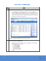
Make sure your host has proper connectivity.
Under Host Management, click on the Connectivity Status and verify your host has
registered with the array
Example:
Note
Once this is verified move on to the next step.
The required software is located in the Course Software Share (please see the
beginning of this lab for exact location).
39
You will need the Windows hotfix file as well as the Emulex driver file.
Once you have copied over the files locally, if the files are in a zip format, please UNZIP
them, if needed, before proceeding!
The installation program will install both the drivers and their configuration programs.
Step
3
Action
For our lab environment, you will need to install a Microsoft Windows 2008 hotfix
KB968675_Storport_Sept2009 before you install the HBA drivers.
4
40
Navigate to the Course Software Share, then to the software folder and then to the
KB968675_Storport_Sept2009 folder
Copy the hotfix locally. Example of the hotfix name: Windows6.0-KB968675-x86.msu
Double click on the executable for the hotfix to launch the update
When the information message comes up click ok
Unlike Windows 2003, you WILL NOT need to reboot the server in order to continue with
the HBA driver install. You can move right to the next step!
Navigate to the Course Software Share, then to the software folder and then to the
Emulex_Windows folder
Copy locally the Windows Emulex software, the driver name is in the format of the
following example: elxocm-windows-x86-5.01.20.04-1.exe
Once downloaded, double-click the icon or filename representing the HBA installation
program to start the installation.
Step
5
Action
This will kick off the HBA install program.
41
Click Run to start the installation process.
Step
6
42
Action
A series of screens will appear displaying information on the program such as where the
program will be stored and install screens.
At the opening install screen of the Emulex OCManager Enterprise click next.
Click Next until you come to the screen that says Install Options and click Finish.
During the install you will get a popup screen asking you to choose what type of
management options you want to implement. Take the defaults.
At the Installation Completed screen click Finish.
Step
7
Action
You have now installed the HBA drivers and the Emulex configuration programs .
8
The first screen shows the HBAs found in the host.
43
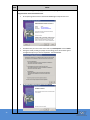
We will explore One Command Manager (OCManager) as an example. It can be
executed from the Start menu, All Programs as shown.
Click one of the adapters to review its configuration.
You’ll see a series of tabs other than Port Information.
Take some time to explore each one.
Step
9
Action
Click the Driver Parameters tab.
44
In the Driver Parameters tab, highlight Link Speed and verify it is set for Auto Detect.
Step
10
11
Action
Next highlight Topology.
Verify it is set for a value of 2.
Read the other choices and their values under the Description.
Note: You should always use EMC-specific drivers. They are installed with settings
configured according to EMC best practices. Most manufacturers will have vendor specific
drivers available for download.
If your Team’s setup has more than one physical HBA then you can return to step 8 of this lab
and perform the same configuration on the other one if it is present on your host.
12
Else go to the next step.
Your HBAs have been installed and setup correctly.
Close the One Command Manager utility.
End of Lab Exercise 4 Part 1
45
Lab 4: Part 2 – Installing PowerPath
Step
1
Action
Install PowerPath
2
The Microsoft Visual C++ 2008 Feature Pack Redistributable Package for x86 (vcredist_x86)
46
The required software is located in the Windows folder in the Course Software Share.
Copy the file locally. If the files are in a zip format, please UNZIP them before
proceeding!
Double click on the appropriate executable to start the installation.
Example: EMCPower.Net32.signed.5.5.b289.exe
You will first be asked to choose a language for the installation. Select English (United
States) and click OK.
If the install prompts you to install the Microsoft Visual C++ 2008 Feature Pack
Redistributable Package for x86 (vcredist_x86) then click Install, else move to the next
step.
Step
3
Action
A Prepare to Install screen appears, followed by a Welcome to Install screen.
3
The legacy AX series Install screen appears.
47
Click Next.
Select No and click Next.
Step
5
Action
Enter a user name and organization in the Customer Information screen.
4
Accept the default folder
48
User: EMC and Organization: EMC should work just fine for the purpose of our labs
Click Next to continue.
Click Next to continue.
Step
5
Action
Choose Typical Install (the default)
6
Click Install to begin installing PowerPath.
49
Click Next.
Accept any defaults until you get to the License Key display.
If you get a security alerts asking if you want to trust the driver installations then click
Yes.
Step
7
Action
An installing screen appears, followed by a License window.
9
50
Enter the license number supplied by the instructor into the License Key field
Or enter 0202htkwhtkw and click Add.
Note: A separate license key is required for each array the host will be accessing.
This license key should not be given out to anyone.
Click OK to continue.
Click Finish to complete the installation.
Step
10
Action
A reboot screen appears
Click Yes to reboot.
When the host successfully reboots, and you are logged in once again, move on to the
next part of the lab.
End of Lab Exercise 4 Part 2
51
Lab 4: Part 3 – Installing the Unisphere Agent
Step
1
Action
Navigate to the Windows folder on the Course Software Share, and copy the Unisphere Host
Agent file locally
2
Next, double-click the Unisphere Host Agent file to launch the install.
The executable name is in the format of the following example:
UnisphereHostAgent-Win-32-x86-en_US-1.1.0.1.0366-1.exe
You are asked whether or not you wish to run software from an unknown publisher
Click Next to proceed past the introductory dialogs.
Accept the default installation location, and click Next.
Verify that the check box for the choice Microsoft iSCSI Initiator – Using iSCSI
IS NOT CHECKED
Click Install to run the installer
Not Checked
52
Step
3
Action
In the Privileged User screen enter in the IP Addresses of your VNX array’s SPs
4
Both SPA and SPB IP Addresses
Click Next when done
Click Done to finish the installation.
End of Lab Exercise 4 Part 3
53
Lab 4: Part 4 – Installing Navisphere Secure CLI
Step
1
Action
Navigate to the Windows folder in the Course Software Share.
2
Introductory Dialog
3
Click Next to proceed past the introductory dialogs.
Accept the default installation location, and click Next.
Leave the Include Navisphere CLI in Environment Path checkbox checked.
54
Double-click the Navisphere Secure CLI file to launch the install.
The executable name is in the format of the following example:
NaviCLI-Win-32-x86-en_US-7.31.0.3.76-1.exe
Click Next.
Click Install to run the installer
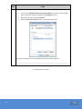
Step
4
Action
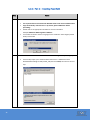
Select Yes when asked if you wish to create a Security File.
5
NaviSecCLI Verification Level settings.
55
Use Username: sysadmin/ Password: sysadmin /Scope: Global for the user parameters.
Click Next.
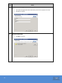
The verification level is used to determine if the certificate sent by the array should or
shouldn’t be verified.
Accept the default LOW setting and click Next.
Step
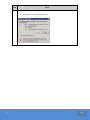
Note
Action
Besides NaviSecCLI other client software like Unisphere Service Manager (USM) and Unisphere
Server Utility will perform certificate verification when connecting to the storage system.
For these applications there are two (2) levels of certificate validation:
o
o
Low = Bypass Certificate Validation
o
All certificates will pass the validation.
o
Default is low so that we will continue to work with existing configurations
Medium = Perform Certificate Validation
o
Certificates will be validated depending on the type of certificate
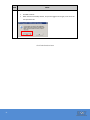
Question: What would need to be done if you installed the NaviSecCLI at a LOW setting and
later on wished to change it to MEDIUM?
_______________________________________________________________________
6
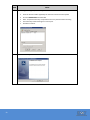
Next click Install to start the installation.
7
Click Done to finish the installation.
End of Lab Exercise 4 Part 4
56
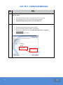
Lab 4: Part 5 – Verifying the VNX Array is Configured to
Auto-Manage hosts
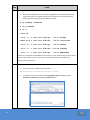
Step
1
Action
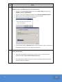
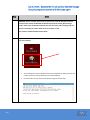
In the address field of Internet Explorer enter the IP address of one of your SPs
followed by “/setup” (without quotes of course).
2
In the Setup display scroll down until you find the Turn Automanage On/Off button.
57
Then authenticate your management account in Unisphere.
Click it to enter the settings.
Step
3
Action
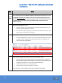
Confirm that Auto Manage is enabled.
Question: What does this setting do?
_________________________________________________________________
_________________________________________________________________
_________________________________________________________________
Hint: Click Help.
End of Lab Exercise 4 Part 5
58
Lab 4: Part 6 – Create and Populate Storage Groups with EMC
Unisphere - Windows
Step
1
Action
System Login:
2
Verify Storage Groups are Enabled:
3
Login to Unisphere from your Windows machine with your sysadmin account credential.
From the Dashboard view, select your VNX from the All System dropdown lists and , System button
on the Navigation Bar.
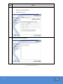
From the System Management menu on the right hand of the screen click System Properties. This
will launch the Storage Systems Properties window.
Click the General tab. Under the Configurations options, locate the checkbox next to Storage
Groups box. This option enables storage group capability for the selected storage system. This
option cannot be disabled, so the check box appears dimmed and is unavailable when Storage
Groups is enabled.
Create a Storage Group:
Click Hosts > Storage Groups from the navigation bar.
From the Storage Groups window, click Create.
o Note: If there is a storage group already created please ignore it.
Name the Storage Group: TeamX_WIN-X where X is your team number. Click OK.
A message asks you “If you would like to add LUNs and connect host to the storage group”, click
No.
Add LUNs to the Storage Group:
59
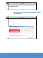
From the Storage Group window select your TeamX_Win-X storage group and click Properties.
Click the LUNs tab. From the Available LUNs window, expand the RG5 and RG6 containers. Use the
scroll bar to see all the available LUNs. Locate the following LUNs (RG5_LUN_50, RG5_LUN_52,
RG6_LUN_ 60, RG_LUN_ 62) and add them to the Storage group by selecting the LUN and clicking
the Add button. Once all the LUNs have been added to the Selected LUNs selection click OK, Yes,
OK.
Step
4
Action
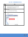
Add a Host to the Storage Group:
5
From the Storage Group window select your TeamX_Win-X storage group and click Properties.
Click the Hosts tab. Select your Physical Windows host (SAN-X where X is your team number) from
the Available Hosts pane and click the to move the hosts to the Hosts to be Connected pane.
Click OK, Yes, OK.
Verify Storage Group Creation:
From the Host Management menu on the right side of the screen click Update All Hosts.
Select your storage system and click Poll. Click Yes. After the Status reads Success followed by the
current date and time click Cancel.
From the Storage Group window select your TeamX_Win-X storage group.
From the Details section click the Hosts tab and verify that your SAN-X host (where X is your team
number) is connected
From the Details section click the LUNs tab and verify that LUNs RG5_LUN_50, RG5_LUN_52,
RG6_LUN_ 60, and RG_LUN_ 62 are connected.
End of Lab Exercise 4 Part 6
60
Lab 4: Part 7 – Configure Windows Host Access to LUNs
Step
1
Action
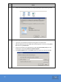
Navigate to the Disk Management menu on your Windows Workstation:
2
On your Windows 2008 workstation, click Start and right-click Computer. Select Manage.
From the Server Manager window, expand the Storage container and select Disk
Management.
An Initialize Disk menu will launch.
o If you do not see four disks that need to be initialized, click Cancel. Select More
Options on the right side of the menu and click Rescan Disks. Once the four disks
have been found right click Disk 1 and click Initialize Disk.
o If you do see four disks that need to be initialized proceed to the next step.
From the Initialize Disk menu screen make sure all four disks are checked and that the MBR (Master
Boot Record) is selected. Click OK.
This will Initialize the disks. Each disk will now be shown as Basic disks that are unallocated.
61
Step
3
Action
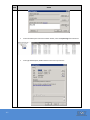
Create New Simple Volumes for each disks:
62
For the four unallocated disks do the following steps:
o Right click the unallocated section next to a disk and select Create New Simple
Volume.
o The New Simple Volume Wizard will appear. Click Next.
o For the Specify Volume Size make sure the Simple volume size in MB matches the
Maximum disk space in MB amount and click Next.
o For Assign the following drive letter use the default and click Next.
o For Format Partition use the defaults but choose Perform a Quick Format and click
Next.
o Review your configuration and click Finish.
Repeat these steps until all unallocated disks have been made into Simple Volumes.
Close Server Manager
Step
4
Action
Verify Simple Volumes on your Windows Workstation:
On your Windows Server click Start and click Computer. You should now see four new
volumes.
What are the drive letters for the new Volumes?
______________________________________________
5
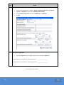
Verify the mounts are seen by the VNX:
In Unisphere, navigate to the Host tab and on the right hand side under Host Management
select Connect Host.
Type in your Windows Physical Server, (SAN-X where X is your team number), host IP address
in the Enter Host IP Address field.
Under Volumes on Block Storage Systems verify that your mount volumes are present.
End of Lab Exercise 4 Part 7
63
Lab 4: Part 8 – Remove the Windows Host from its Storage
Group in prepartion for the Linux Labs
Step
Note
Action
REMINDER: Please remember that in order to do both sets of labs for Windows and Linux, you will need to
remove the Windows Production host from the TeamX_WIN-X storage group in order to put the RedHat
Production host into the TeamX_LIN-X storage group (yet to be created) and vice-versa each time you need
to work on one or the other in a lab.
This cannot be avoided with dual-booted hosts!
1
In Unisphere remove your Windows Host from its storage group.
64
If needs be, login to Unisphere from your Linux machine with your sysadmin account credentials.
From the Dashboard view, select your VNX from the All System dropdown lists.
Click Hosts > Storage Groups from the navigation bar.
Right-mouse click on your Storage Group and choose Properties
Step
2
Action
Remove the Windows 2008 server from the “Hosts to be Connected” column
Note
In the Properties screen remove your Physical Windows 2008, SAN-X, host by hightlighting the host in
the “Hosts to be Connected” column and moving it to the “Available Hosts” column.
Click Apply, Yes to the Confirmation Message and OK to the Success Message
Then OK to Close the Storage Group Proprties screen
Example:
You are ready to move on to the next part of the Labs on Linux
End of Lab Exercise 4
65
66
Lab Exercise 5: Configuring Host Access to VNX LUNs - Linux
Purpose:
The purpose of this series of labs is to setup your PHYSICAL Linux host
(SAN-X where X is your team number) with the proper drivers and
software needed for appropriate communication with the VNX Array. You
will also create Storage Groups with EMC Unisphere in order to
implement Access Logix and have the hosts access the provisioned luns
through logical volume management.
Please remember that if you choose to do both sets of labs
for Windows and Linux then you will need to remove the
Windows Production host from the TeamX_WIN-X storage
group in order to put the RedHat Production host into the
TeamX_LIN-X storage group and vice-versa each time you
need to work on one or the other in a lab.
This cannot be avoided with physical dual-booted hosts!
There has been a Course Software Share set up for your Team on
a Linux host at the following address: 10.127.XX.163
(Ask your instructor for the correct IP Address which may vary
per class)
From Linux:
Open a terminal window and FTP to the 10.127.XX.163
Course Software Share host system.
username: ftp
password: any number or letter followed by @
67
You may wish to create a folder for the appropriate software, cd
to that folder and then FTP to the Course Software Share in order
to do the FTP get command download to the folder of your
choice.
Tasks:
68
Students perform the following tasks:
Install HBA drivers
Install PowerPath
Install the Unisphere Agent
Install Navisphere Secure CLI
Create a Storage Group on a VNX storage system with EMC
Unisphere
Add LUNs and hosts to a Storage Group with EMC Unisphere
Identify LUNs assigned to specific hosts
Obtain host LUN status information from EMC Unisphere
Use Linux utilities to make VNX LUNs usable to a Linux host
Lab 5: Part 1 - Installing Emulex Drivers on a Linux host
Step
Action
1
Reboot the Windows host into Linux by double-clicking on the boot_rhel4 icon on the desktop.
2
Hit the spacebar to close the command prompt and then reboot the Windows server.
Give the server sufficient time to reboot and then open the GUI to your Linux server
through your student web presentation page
When the system reboots, ensure the dual boot host is running Linux or has booted into
Linux.
Create a folder called SAN_Machine_apps
Open a terminal window and create a folder called SAN_Machine_apps from the root
directory
Example:
3
mkdir SAN_Machine_apps
Change directory to the SAN_Machine_apps
Change directory to the SAN_Machine_apps directory
Example:
cd SAN_Machine_apps
4
Create the Emulex_apps directory within the SAN_Machine_apps directory and change to that
directory
Create the /Emulex_apps directory within the SAN_Machine_apps directory and change
to that directory
Example:
69
5
From the Course Software Share, download the Emulex Drivers from the software\Linux\Emulex_Linux\
directory.
6
The file is called elxocm-rhel5-sles10-5.0.17.4-1.tar
Example:
You will need to switch over to Binary in order to download the software in the proper format!
Example:
7
70
Quit the FTP session and verify the file downloaded properly to your Emulex_apps directory.
8
Extract the source files.
Type tar xvf ElxLinuxApps-2.1a8-8.0.x.y.tar
This extraction will install the files into a new directory.
Read the messages and note the directory name
Example:
tar xvf elxocm-rhel5-sles10-5.0.17.4-1.tar
elxocm-rhel5-sles10-5.0.17.4-1/
elxocm-rhel5-sles10-5.0.17.4-1/i386/
elxocm-rhel5-sles10-5.0.17.4-1/i386/jre/
elxocm-rhel5-sles10-5.0.17.4-1/i386/jre/elxocmjvm-5.0.17.4-1.i386.rpm
elxocm-rhel5-sles10-5.0.17.4-1/i386/rhel-5/
elxocm-rhel5-sles10-5.0.17.4-1/i386/rhel-5/elxocmlibhbaapi-5.0.17.41.i386.rpm
elxocm-rhel5-sles10-5.0.17.4-1/i386/rhel-5/elxocmcore-5.0.17.4-1.i386.rpm
...
elxocm-rhel5-sles10-5.0.17.4-1/x86_64/rhel-5/elxocmjvm-5.0.17.41.x86_64.rpm
elxocm-rhel5-sles10-5.0.17.4-1/x86_64/sles-10/
elxocm-rhel5-sles10-5.0.17.4-1/x86_64/sles-10/elxocmlibhbaapi-32bit5.0.17.4-1.x86_64.rpm
elxocm-rhel5-sles10-5.0.17.4-1/x86_64/sles-10/elxocmlibhbaapi-5.0.17.41.x86_64.rpm
elxocm-rhel5-sles10-5.0.17.4-1/x86_64/sles-10/elxocmcore-5.0.17.41.x86_64.rpm
elxocm-rhel5-sles10-5.0.17.4-1/x86_64/sles-10/elxocmgui-5.0.17.41.x86_64.rpm
elxocm-rhel5-sles10-5.0.17.4-1/x86_64/sles-10/elxocmjvm-5.0.17.41.x86_64.rpm
elxocm-rhel5-sles10-5.0.17.4-1/install.sh
elxocm-rhel5-sles10-5.0.17.4-1/uninstall.sh
71
9
Change to the new directory
Change to the new directory noted above.
Run the installer script by typing ./install.sh
Example:
[root@SAN-6 /]# cd elxocm-rhel5-sles10-5.0.17.4-1
[root@SAN-6 elxocm-rhel5-sles10-5.0.17.4-1]# ls -l
total 298056
drwxr-xr-x 6 root root
5.0.17.4-1
4096 Dec 15
-rw-r--r-- 1 root root 304892095 Jun
5.0.17.4-1.tar
2009 elxocm-rhel5-sles10-
8 11:58 elxocm-rhel5-sles10-
[root@SAN-6 elxocm-rhel5-sles10-5.0.17.4-1]# ./install.sh
10
The installer package begins the installation process.
Example:
[root@SAN-6 elxocm-rhel5-sles10-5.0.17.4-1]# ./install.sh
Beginning OneCommand Manager Enterprise Kit Installation...
Installing ./i386/rhel-5/elxocmlibhbaapi-5.0.17.4-1.i386.rpm
Installing ./i386/rhel-5/elxocmcore-5.0.17.4-1.i386.rpm
Installing ./i386/rhel-5/elxocmjvm-5.0.17.4-1.i386.rpm
Installing ./i386/rhel-5/elxocmgui-5.0.17.4-1.i386.rpm
Starting fcauthd: FC Authentication Daemon: 1.22
[
OK
]
Starting OneCommand Manager Management Daemon: [
...
72
OK
]
11
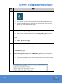
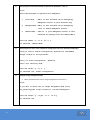
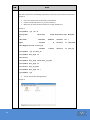
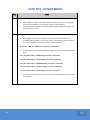
When prompted to select desired mode of operation for HBAnyware, select “3”.
Example:
Select desired mode of operation for HBAnyware
1
Local Mode
: HBA's on this Platform can be managed by
HBAnyware clients on this Platform Only.
2
Managed Mode: HBA's on this Platform can be managed by
local or remote HBAnyware clients.
3
Remote Mode : Same as '2' plus HBAnyware clients on this
Platform can manage local and remote HBA's.
Enter the number '1' or '2' or '3' 1
You selected: 'Remote Mode'
12
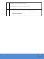
When prompted to select, chose to Enable the configuration features for OneCommand Manager.
Would you like to enable configuration features for OneCommand
Manager clients on this platform?
Enter y to allow configuration. (default)
Enter n for read-only mode.
Enter the letter 'y' or 'n' y
You selected: Yes, enable configuration
13
Setting the change management mode
When prompted to allow user to change management mode choose Y
Example:
Do you want to allow user to change management mode using
set_operating_mode script located in /usr/sbin/hbanyware ?
Enter the letter 'y' if yes, or 'n' if no y
You selected: Yes
73
14
The HBAnyware installation will be complete at this point.
OneCommand Manager Enterprise Kit install completed successfully.
NOTE
74
The Emulex LPFC driver is part of the Linux Kernel and WILL NOT have to be reloaded.
OPTIONAL: Since you have a GUI interface to your Linux server, you will also be able to run the
OneCommand Manager GUI client.
cd /usr/sbin/hbanyware/ocmanager
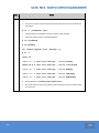
15
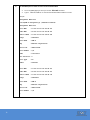
Run the HBAnyware CLI client to view a list of all installed HBAs
To run the HBAnyware CLI client you use the ./hbacmd command
Type in ./hbacmd listhbas to view all of the Emulex HBAs installed in a server.
Example:
Manageable HBA List
[root@SAN-6 hbanyware]# ./hbacmd listhbas
Manageable HBA List
Port WWN
: 10:00:00:00:c9:6a:a2:62
Node WWN
: 20:00:00:00:c9:6a:a2:62
Fabric Name : 10:00:00:05:1e:34:19:ad
Flags
: 8000fa00
Host Name
: SAN-6
Mfg
: Emulex Corporation
Serial No.
: VM73172221
Port Number : n/a
Mode
: Initiator
PCI Function: 0
Port Type
: FC
Model
: LP10000
Port WWN
: 10:00:00:00:c9:6a:a2:63
Node WWN
: 20:00:00:00:c9:6a:a2:63
Fabric Name : 10:00:00:05:1e:34:3e:7d
Flags
: 8000fa00
Host Name
: SAN-6
Mfg
: Emulex Corporation
Serial No.
: VM73172221
Port Number : n/a
…
75
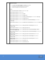
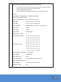
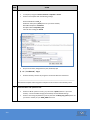
16
List firmware versions, serial numbers, WWN
To list firmware versions, serial numbers, WWN and a variety of model specific
information, type in: ./hbacmd hbaattrib <wwpn>
Take some time to look through the different types of information listed here.
Example:
[root@SAN-6 hbanyware]# ./hbacmd hbaattrib
10:00:00:00:c9:6a:a2:62
HBA Attributes for 10:00:00:00:c9:6a:a2:62
Host Name
: SAN-6
Manufacturer
: Emulex Corporation
Serial Number
: VM73172221
Model
: LP10000
Model Desc
: Emulex LP10000 2Gb PCI-X Fibre Channel Adapter
Node WWN
: 20 00 00 00 c9 6a a2 62
Node Symname
: Emulex LP10000 FV1.91A1 DV8.2.0.63.3p
HW Version
: 1001206d
Opt ROM Version: 5.01a5
FW Version
: 1.91A1 (T2D1.91A1), sli-2
Vendor Spec ID : 10DF
Number of Ports: 1
Driver Name
: lpfc
Device ID
: FA00
HBA Type
: LP10000
Operational FW : SLI-2 Overlay
SLI1 FW
: 1.91a1
SLI2 FW
: 1.91a1
IEEE Address
: 00 00 c9 6a a2 62
Boot Code
: Enabled
Boot Version
: 5.01a5
...
76
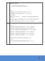
17
View host port information, fabric parameters and # of ports zoned
To view host port information (e.g., port speed, device paths) and fabric parameters
(e.g., fabric ID (S_ID), # of ports zoned along with this port),
type in: ./hbacmd portattrib <wwpn>
Take some time to look through the different types of information listed here.
Example:
[root@SAN-6 hbanyware]# ./hbacmd portattrib
10:00:00:00:c9:6a:a2:62
Port Attributes for 10:00:00:00:c9:6a:a2:62
Node WWN
: 20 00 00 00 c9 6a a2 62
Port WWN
: 10 00 00 00 c9 6a a2 62
Port Symname
: Emulex PPN-10:00:00:00:c9:6a:a2:62
Port FCID
: 10C00
Port Type
: Fabric
Port State
: Operational
Port Service Type
: 8
Port Supported FC4
: 00 00 01 00 00 00 00 01
00 00 00 00 00 00 00 00
00 00 00 00 00 00 00 00
00 00 00 00 00 00 00 00
Port Active FC4
: 00 00 01 00 00 00 00 01
00 00 00 00 00 00 00 00
00 00 00 00 00 00 00 00
00 00 00 00 00 00 00 00
Port Supported Speed: 1 2 GBit/sec
Port Speed
: 2 GBit/sec
Max Frame Size
: 2048
OS Device Name
: /sys/class/scsi_host/host1
Num Discovered Ports: 4
77
Fabric Name
: 10 00 00 05 1e 34 19 ad
Function Type
: FC
18
View HBA attributes for the server
In order to view HBA attributes for the server, type in: ./hbacmd serverattrib <wwpn>
Take some time to look through the different types of information listed here.
Example:
[root@SAN-6 hbanyware]# ./hbacmd serverattrib
10:00:00:00:c9:6a:a2:62
Server Attributes for 10:00:00:00:c9:6a:a2:62
Host Name
: SAN-6
FW Resource Path
: /usr/sbin/hbanyware/RMRepository/
DR Resource Path
: /usr/sbin/hbanyware/RMRepository/
OneCommand Mgr. Server Ver. : 33.0.17.4
Host OS Version
19
: Linux2.6.18-194.el5PAE i686
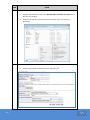
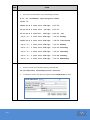
View HBA attributes for the driver parameters
In order to view HBA attributes for the driver parameters,
type in ./hbacmd getdriverparams <wwpn>
Current values are shown under the Cur heading within the box
Example:
[root@SAN-6 hbanyware]# ./hbacmd getdriverparams 10:00:00:00:c9:6a:a2:62
Driver Params for 10:00:00:00:c9:6a:a2:62. Values in HEX format.
DX
string
Low
High
Def
00:
log-verbose
0
ffff
01:
lun-queue-depth
1
02:
scan-down
03:
Exp
Dyn
0
0 800d
1
80
1e
1e 800d
2
0
1
1
1 800d
2
nodev-tmo
0
ff
1e
1e 800d
1
04:
topology
0
6
0
0 800d
2
05:
link-speed
0
8
0
0 800d
2
06:
fcp-class
2
3
3
3 800d
2
07:
use-adisc
0
1
0
0 800d
1
08:
ack0
0
1
0
0 800d
2
09:
cr-delay
0
3f
0
0 800d
2
...
78
Cur
20
Verify the Link Speed for the previous output is set for Auto Select.
Verify the Link Speed is set for Auto Select. The following is from The HBAnyware Utility
User Manual:
Verify the Topology is set for a value of 0x00.
Note: You should always use EMC-specific drivers. They are installed with settings
configured according to EMC best practices.
End of Lab Exercise 5 Part 1
79
Lab 5: Part 2 - Installing PowerPath Software on a Linux Host
Step
Note
Action
Before you install PowerPath in working environments note that installing or upgrading
PowerPath requires you to reboot the host.
Plan to install or upgrade PowerPath when a reboot will cause minimal site disruption.
In this lab, you install PowerPath 5.5 for Linux
1
Before you install PowerPath ensure that:
No devices are currently managed by Linux MPIO
Run a dmsetup ls
Run a chkconfig --list |grep multipathd
Example:
[root@SAN-6 ~]# dmsetup ls
No devices found
[root@SAN-6 ~]# chkconfig --list |grep multipathd
multipathd
0:off
1:off
2:off
3:off
4:off
5:off
6:off
The multipath daemon does not startup upon boot
All devices are blacklisted in the /etc/multipath.conf file
On all systems in your lab this has already been done for you
To check this run more /etc/multipath.conf
Example:
[root@SAN-6 ~]# more /etc/multipath.conf
# This is a basic configuration file with some examples, for device mapper
# multipath.
# For a complete list of the default configuration values, see
...
# Blacklist all devices by default. Remove this to enable multipathing
# on the default devices.
blacklist {
devnode "*"
}...
80
Step
2
Action
Change directory to the SAN_Machine_apps
Change directory to the SAN_Machine_apps directory
Example:
cd SAN_Machine_apps
3
Within the SAN_Machine_apps directory create a Powerpath_app folder to copy the
PowerPath software to.
4
cd to the Powerpath_app directory and copy the PowerPath software to it from the FTP
Server.
Once you have established the ftp connection then change directory to software/Linux/
Example file name is EMCPower.LINUX.5.5.GA.b275.tar.gz
Don’t forget to change to binary “bin” before the transfer
Use the get command to transfer the file to your local Powerpath_app directory
Once completed quit FTP and verify file downloaded to the Powerpath_app directory
Example:
81
5
If needed, then untar the PowerPath archive.
6
Type: tar -xzf EMCPower.LINUX.5.5.GA.b275.tar.gz
Else go to the next step.
Install PowerPath for Linux
To install PowerPath
Type: rpm -i EMCPower.LINUX-5.5.0.00.00-275.RHEL5.i386.rpm
You will get back a legacy message like this:
All trademarks used herein are the property of their respective
owners.
NOTE: License registration is not required to manage the CLARiiON
AX series array.
Move on to the next step.
7
Register PowerPath on the host.
Type: emcpreg –install
Enter y at the prompt.
When prompted, enter the 24-character alphanumeric sequence supplied here and press ENTER.
Be sure to use hyphens to separate groups of four alphanumeric characters without any spaces.
In the Lab you will use License Key: B4P9-DB4Q-LF6W-Q0SA-ML90-VRL4
(those are zeros, not Os !!)
Important: The license key should not be given out to anyone.
If you enter a valid registration key, you see a Key successfully installed message.
Example
emcpreg -install
===========
EMC PowerPath Registration ===========
Do you have a new registration key or keys to enter?[n] y
Enter the registration keys(s) for your product(s),
one per line, pressing Enter after each key.
After typing all keys, press Enter again.
Key (Enter if done): B4P9-DB4Q-LF6W-Q0SA-ML90-VRL4
1 key(s) successfully added.
Key successfully installed.
82
7
Start PowerPath.
Type: /etc/init.d/PowerPath start
Example
[root@RH-Production8 PowerPath]# /etc/init.d/PowerPath start
Starting PowerPath:
8
done
Reboot the Linux server to finalize the Linux Powerpath installation
At the prompt type shutdown -r -t 1 now
Example:
[root@RH-Production8 PowerPath]# shutdown -r -t 1 now
Broadcast message from root (pts/1) (Wen Jun 8 18:39:05 2011):
The system is going down for reboot NOW!
End of Lab Exercise 5 Part 2
83
Lab 5: Part 3 - Install the Unisphere Agent & Navisphere Secure
CLI software on your Linux host
Step
Note
Action
In order to run the Host Agent or Navisphere Secure CLI, your Linux host must have the HBA
hardware and driver installed properly. Please make sure it is before proceeding. If you need
to then contact your instructor for assistance.
You should be familiar with the FTP process at this point. In order to be more concise we will be
more specific with our directions going forward in this lab.
1
Change directory to the SAN_Machine_apps
Change directory to the SAN_Machine_apps directory
Example:
cd SAN_Machine_apps
2
Create two folders in the SAN_Machine_apps directory for your agent and your Secure CLI
software.
84
Within the SAN_Machine_apps directory create a Host_Agent directory to copy the
Unisphere Host Agent software to.
Within the SAN_Machine_apps directory create a NaviSecCLI directory to copy the
Navisphere Secure CLI software to.
3
cd to the Host_Agent directory and copy the Unisphere Host Agent software to it from the FTP Server.
4
cd to the NaviSecCLI directory and copy the Navisphere Secure CLI software to it from the FTP Server.
85
Establish an ftp connection with the Course Software Share then change directory to
software/Linux/
Example file name is:
HostAgent-Linux-32-x86-en_US-1.1.0.1.0366-1.i386.rpm
Don’t forget to change to binary “bin” before the transfer
Use the get command to transfer the file to your local Host_Agent directory
Once completed quit FTP and verify file downloaded to the Host_Agent directory
Establish another ftp connection with the Course Software Share then change directory to
software/Linux/
Example file name is:
NaviCLI-Linux-32-x86-en_US-7.31.0.3.66-1.i386.rpm
Don’t forget to change to binary “bin” before the transfer
Use the get command to transfer the file to your local NaviSecCLI directory
Once completed quit FTP and verify file downloaded to the NaviSecCLI directory
5
Install the Host Agent and CLI software:
Install both the agent and CLI using the rpm command as shown below
Please set the security setting to LOW on the Navisphere Secure CLI
Then verify that the Host Agent and Navisphere Secure CLI are installed and running
Examples:
cd Host_Agent
rpm -ivh HostAgent-Linux-32-x86-en_US-1.1.0.1.0366-1.i386.rpm
Preparing...
########################################### [100%]
1:HostAgent-Linux-32-x86-############################# [100%]
rpm -ivh NaviCLI-Linux-32-x86-en_US-7.31.0.3.66-1.i386.rpm
Preparing...
########################################### [100%]
1:NaviCLI-Linux-32-x86-en############################# [100%]
Please enter the verifying level(low|medium|l|m) to set?
l
Setting low verifying level
rpm -qa |more |grep NaviCLI
NaviCLI-Linux-32-x86-en_US-7.31.0.3.66-1
rpm -qa |more |grep HostAgent
HostAgent-Linux-32-x86-en_US-1.1.0.1.0366-1
86
6
Edit the $HOME/.bash_profile to add Navisphere Secure CLI and the Unisphere agent to the
path statement.
It is HIGHLY suggested that you make backups of these files BEFORE you change them.
Example:
ls -al |grep .bash
-rw-------
1 root root
8474 Jun
9 11:58 .bash_history
-rw-r--r--
1 root root
24 Jul 12
-rw-r--r--
1 root root
191 Jul 12
2006 .bash_profile
-rw-r--r--
1 root root
176 Jul 12
2006 .bashrc
2006 .bash_logout
cp .bash_profile .bash_profile_backup
cp .bashrc .bashrc_backup
7
Use a text editor to edit the $HOME/.bash_profile to add Navisphere Secure CLI and the
Unisphere agent to the path statement.
You can use the GUI text editor to modify these quicker if you are not familiar with the
vi tool
You will have to “show hidden files” if you use the GUI text editor
The modified entry should add the entries for /opt/Navisphere/bin and
/opt/Unisphere/bin
Examples:
87
8
Once this is done run the following to make sure the new .bash_profile is loaded by forcing the
file to be read in.
Example: (Output for example only has been modified to read easier)
. .bash_profile
echo $PATH
:/usr/kerberos/sbin:/usr/kerberos/bin:/usr/local/sbin
:/usr/local/bin:/sbin:/bin:/usr/sbin:/usr/bin:/root/bin
:/root/bin
:/opt/Navisphere/bin
:/opt/Unisphere/bin
9
Verify Privileged Users in the agent.config file.
Verify Privileged Users in the agent.config file.
The entry for the root user should be automatically created so you should just need to
verify this
Change to the /etc/Unisphere directory and using the ls command look for the file:
agent.config file.
Open the file with the more command and search for user.
To search the file type / followed by user.
Notice the line that starts with user root.
That is the administrative Privileged User.
Example:
[root@SAN-6 Unisphere]# more agent.config
...
/root
...
user root
# only on this machine
#user sblue@picasso
"picasso"
# individual user "sblue" on host
#user lgreen@hannibal
"hannibal"
# individual user "lgreen" on host
...
88
10
Restart the Host Agent
Enter the following commands from the root directory to stop and restart the agent:
/etc/init.d/hostagent stop (only one space; between agent and stop.)
/etc/init.d/hostagent start
/etc/init.d/hostagent status
Example:
/etc/init.d/hostagent stop
Shutting down hostagent:
[
OK
]
[
OK
]
/etc/init.d/hostagent start
Starting Navisphere agent:
/etc/init.d/hostagent status
hostagent (pid 7286) is running...
End of Lab Exercise 5 Part 3
89
Lab 5: Part 4 - Create and Populate Storage Groups with EMC
Unisphere – Linux
Step
1
Action
System Login:
2
Optional
Verify Storage Groups are Enabled:
Step
3
We have already verified that Storage Groups were enabled in the last lab so it is not
necessary for this lab. However feel free to practice the steps if you wish, else move
to the next step.
From the System Management menu on the right of the screen, click System
Properties. This launches the Storage Systems Properties window.
Click the General tab. Under the Configurations options, locate the checkbox next to
Storage Groups box. This option enables storage group capability for the selected
storage system. This option cannot be disabled, so the check box appears dimmed
and is unavailable when Storage Groups is enabled.
Create a Storage Group:
90
Login to Unisphere from your Physical Linux host (SAN-X where X is your team
number) machine with your sysadmin account credential.
From the Dashboard view, select your VNX from the All System dropdown lists and
click System on the Navigation Bar.
Click Hosts > Storage Groups from the navigation bar.
From the Storage Groups window click Create.
o Note: If there is a storage group already created please ignore it.
Name the Storage Group: TeamX_Linux-X where X is your team number. Click OK.
A message will ask you “if you would like to add LUNs and connect host to the
storage group”,
Click No.
Step
4
Action
Add LUNs to the Storage Group:
5
Add a Host to the Storage Group:
91
From the Storage Group window select your TeamX_Linux-X storage group and click
Properties.
Click the LUNs tab. From the Available LUNs window, expand the RG5 and RG6
containers. Use the scroll bar to see all the available LUNs. Locate the following LUNs
(RG5_LUN_54, RG6_LUN_64) and add them to the Storage group by selecting the
LUN and clicking the Add button.
In the Selected LUNs window click the Host ID field and give RG5_LUN_54 a Host ID
of 54
In the Selected LUNs window click the Host ID field and give RG6_LUN_64 a Host ID
of 64.
o Note: The Host IDs are used by the Linux server to see the LUNs
Click OK, Yes, OK.
From the Storage Group window select your TeamX_Linux-X storage group and click
Properties.
Click the Hosts tab. Select your Physical Linux host (SAN-X where X is your team
number) from the Available Hosts pane and click the to move the hosts to the
Hosts to be Connected pane. Click OK, OK.
Step
6
Action
Verify Storage Group Creation:
7
From the Host Management menu on the right side of the screen click Update All
Hosts.
Select your storage system and click Poll. Click Yes. After the Status reads Success
followed by the current date and time click Cancel.
From the Storage Group window select your TeamX_Linux-X storage group.
From the Details section click the Hosts tab and verify that your SAN-X host (where X
is your team number) is connected
From the Details section click the LUNs tab and verify that LUNs RG5_LUN_54, and
RG_LUN_ 64 are connected.
Reboot the Linux Server and log back into the system when it comes back up.
In order to refresh and rescan the logical volume management of the Linux server.
Example:
[root@SAN-6 ~]# shutdown -r -t 1 now
End of Lab Exercise 5 Part 4
92
Lab 5: Part 5 - Configure Linux Host Access to LUNs
Step
Note
Please
Read!
1
Action
The portions of these labs for Linux Logical Volume Management were
designed and captured using the Linux GUI. If you have the requisite
knowledge and feel more comfortable using the Command Line then please
do so. You can find an example script in the Appendix section immediately
following this lab, Lab 5: Part 5.
Run a Powermt display to see the new devices that you have allocated to your host.
From the Terminal window run a powermt display dev=all
What is some of the information that you can use here to identify specifics about
each of the volumes?
______________________________________________________________________
Example:
93
Step
2
Action
Navigate to the Disk Management menu on your Linux Workstation. This GUI may be a bit
SLOW so please be patient!
3
Navigate to the Logical Volume Management menu on your Linux Workstation.
94
On your Linux workstation, click System, Administration and select Logical Volume
Management.
From the LVM screen, expand the uninitialized entries on the left hand side of the
screen
If you do see 2 emcpower devices that need to be initialized then proceed
(else contact your instructor for assistance)
Click on the Initialize Entry at the bottom of the screen.
Step
4
Action
Click Yes to the warning message that will pop up.
Example:
5
Click Yes to the Information message that will pop up.
Example:
95
Step
6
Action
Once this is complete you will notice an unallocated colume heading now appearing on the
left side on the screen with a new entry of the device that you just initialized and formatted.
Example:
96
Step
7
Action
Create a new Volume Group for the device
97
Click on the device you wish to create a new volume group for
Next click New Volume Group at the bottom of the screen.
Name the Volume Group “Linux1” and take the defaults for the rest of the options.
Step
8
Action
Create a new Logical Volume for the device
Click on the logical device you wish to create a new logical volume for
Next click Create New Logical Volume at the bottom of the screen.
Example:
98
Step
9
Action
Name the new Logical Volume
Give it an LV name of Linux1_LV
Click on Use remaining to use the remaining free space of the Logical Volume in the
Volume Group
Give it a Filesystem of Ext3
Check off Mount
Check off Mount when rebooted
Give it a mount pount of /mnt_r5
Click OK
Example:
10
Click Yes to create the new mount point.
Example:
99
Step
11
Action
When the task completes you should see you new Linux1_LV logical volume under the Linux1
Volume Group.
What types of information can you tell from the Properties for Logical Volume
properties on the right-hand side of the screen?
______________________________________________________________________
______________________________________________________________________
100
Step
12
Action
From a terminal window navigate to the new drive and place a new text file on it.
Note: We use the CLI for the following steps but if you wish you may use the GUI. See below in
Example 2.
Use a df –k command to see the newly mounted drive
Create a new file call touch mnt_r5_text on the drive
Make sure you leave the drive so there are no open handles on it
Example 1:
[root@SAN-6 ~]#
Filesystem
on
df -k
1K-blocks
/dev/sda2
Used Available Use% Mounted
14067580
3588364
9753080
2075920
8
2075912
1% /dev/shm
141440
4753104
3% /mnt_r5
tmpfs
27% /
/dev/mapper/Linux1-Linux1_LV
5156480
[root@SAN-6 ~]# cd /mnt_r5
[root@SAN-6 mnt_r5]# ls
lost+found
[root@SAN-6 mnt_r5]# touch mnt_r5_text
[root@SAN-6 mnt_r5]# ls
lost+found
mnt_r5_text
[root@SAN-6 mnt_r5]# cd /
[root@SAN-6 /]#
This can also be done through the GUI
Example 2:
101
Step
13
Action
Repeat all of these steps for your Raid 6 LUN as well.
14
Information needed to create the drive is as follows
o Volume Group Name = Linux2
o Logical Volume = Linux2_LV
o Use all of the free space of the Logical Volume in the Volume Group
o Give it a Filesystem of Ext3
o Check off Mount
o Check off Mount when rebooted
o Give it a mount pount of /mnt_r6
o Create a new file called mnt_r6_text on the drive
Verify the mount points are seen in the VNX Array:
In Unisphere, navigate to Hosts > Storage Groups
Go to the Host tab and on the right hand side under Host Management select
Connect Host.
Type in your SAN-X host IP address in the Enter Host IP Address field.
Under Volumes on Block Storage Systems verify that your mount volumes are
present.
NOTE: This step may be a bit problematic for you as it was in the writing of this lab. This is
because of the dual boot nature of the hosts we are working with in our student labs.
End of Lab Exercise 5 Part 5
102
Lab 5: Part 6 - Remove the the Linux Host from the Storage
Group in prepartion to work with Windows again
Step
Note
Action
REMINDER: Please remember that in order to do both sets of labs for Windows and Linux ,
you will need to remove the Windows Production host from the TeamX_WIN-X storage
group in order to put the RedHat Production host into the TeamX_LIN-X storage group and
vice-versa each time you need to work on one or the other in a lab.
This cannot be avoided with dual-booted hosts!
1
Prepare to Reboot the Linux host into Windows by double-clicking on the Boot to Windows
icon on the desktop.
103
This will bring up a Terminal Window. Read the message that the batch job echos and
confirm you have just setup Windows as the default boot OS.
Hit the spacebar to close the terminal window and go to the next step.
Step
2
Action
In Unisphere open the Properties of your Linux Host from its storage group.
If needed then login to Unisphere from your Linux machine with your sysadmin
account credentials.
From the Dashboard view, select your VNX from the All System dropdown lists.
Click Hosts > Storage Groups from the navigation bar.
Right-mouse click on your Storage Group and choose Properties
Example:
3
Remove the Linux server from the Storage Group
104
In the Properties screen remove your Linux SAN-X host by hightlighting the host in
the “Hosts to be Connected” column and moving it to the “Available Hosts” column.
Click Apply, Yes to the Confirmation Message and OK to the Success Message
Then OK to Close the Storage Group Proprties screen
4
Prepare the Windows Hosts to be used once again by adding it back to it’s storage group
5
Reboot the Linux host into Windows by running a Reboot from a Terminal window
6
Give the server sufficient time to reboot and then open the GUI to your Windows
server through your Student Web Presentation page.
Check the Windows 2008 Logical Volume Manager
Note
The host should reboot at this point.
Wait an appropriate amount of time and log back into your Windows 2008 server.
7
From the Storage Group window select your TeamX_Win-X storage group and click
Properties.
Click the Hosts tab. Select your Physical Windows host (SAN-X where X is your team
number) from the Available Hosts pane and click the .to move the hosts to the
Hosts to be Connected pane. Click OK, Yes, OK.
Using Logical Disk Management verify that all of your disks and file systems are
operational.
You are ready to move on to the next part of the Labs
End of Lab Exercise 5 Part 6
105
Lab 5: Part 6 Addendum – Partition Linux Devices through the
Command Line Interface
106
Note
These steps are provided as EXAMPLE steps of how to format your LUNs for
your Linux Server. Please read through the steps in the LVM lab, Lab 5: Part 5 Configure Linux Host Access to LUNs, so you know how they compare to the
steps below.
INFO
Raid 5 LUN as information needed.
Raid 6 LUN as information needed.
Information needed to create the drive is
as follows
o Volume Group Name = Linux1
o Logical Volume = Linux1_LV
o Use all of the free space of the
Logical Volume in the Volume
Group
o Give it a Filesystem of Ext3
o Give it a mount pount of /mnt_r5
o Create a new file call touch
mnt_r5_text on the drive
Information needed to create the drive is
as follows
o Volume Group Name = Linux2
o Logical Volume = Linux2_LV
o Use all of the free space of the
Logical Volume in the Volume
Group
o Give it a Filesystem of Ext3
o Give it a mount pount of /mnt_r6
o Create a new file call touch
mnt_r6_text on the drive
1
Partition the disk and create a file system on the pseudo-device:
From your Linux-X host (Putty command prompt), run the following commands:
o Type fdisk /dev/emcpowere
o A warning will appear. To get to the help menu type m
o Create a new partition. Type n
o Create a Primary Partition. Type p
o For the number of Partitions type 1
o For the first cylinder type in the maximum amount.
o Write Table to disk and exit. Type w
o
o
o
o
o
o
o
Type fdisk /dev/emcpowerf
A warning will appear. To get to the help menu type m
Create a new partition. Type n
Create a Primary Partition. Type p
For the number of Partitions type 1
For the first cylinder type in the maximum amount.
Write Table to disk and exit. Type w
This will create emcpowere1 and emcpowerf1.
2
Mount and verify the device:
3
From your Linux-X host (Putty command prompt), run the following commands:
o Type mount /dev/emcpowere1 /mnt_5
o Type mount /dev/emcpowerf1 /mnt_6
Verify the mounts are seen by the VNX:
107
From your Linux-X host (Putty command prompt), run the following commands:
o Type mkfs.ext3 /dev/emcpowere1
o Type mkfs.ext3 /dev/emcpowerf1
From your Linux-X host (Putty command prompt), run the following commands:
o Create a mount point for the device. Type mkdir /mnt_5
o Create a mount point for the device. Type mkdir /mnt_6
In Unisphere, navigate to the Host tab and on the right hand side under Host
Management select Connect Host.
Type in your SAN-X host IP address in the Enter Host IP Address field.
Under Volumes on Block Storage Systems verify that your mount volumes are present.
Close Unisphere
Lab 5: Part 7 – VNX iSCSI Port Configuration Information
Confirmation
Step
Note
PLEASE
READ!
1
Action
In these following labs, for Windows and Linux, you will be confirming the configuration of
iSCSI connectivity of the Virtual Machine (VM) hosts that have been assigned to your team.
See Appendix F for details. You will not need to be concerned with dual-booting because
these are two separate VMs that have been assigned to your team. These hosts will also be
used specifically for later labs that deal with SnapView Snaps, SnapView Clones and
SnapSure Snapshots.
Open the Port Management screen.
2
Verify Properties
3
From the “Settings” menu, select “Network”, then select “Settings for Block”. This
will bring up the Port Management screen.
You can choose to filter by “type” if you wish to. This will make it easier to see which
types of ports you currently have configured.
In the “Port Management” window, click on the iSCSI ports (Windows hosts connect
to A5/B5 and Linux to A6/B6) whose network parameters were assigned to your
Team to verify and click Properties.
Verify the IQN is displayed and note the “Physical Port Properties” values.
Selecting “ADD” from the window will launch the IPv4 Configuration dialog box in
iSCSI Virtual Port Properties window appears. This is where the user would enter the
configuration information on a new system. DO NOT ADD PORTS.
Click on the “Virtual Port 0” and select Properties
Take a moment to review the parameters for the port.
Note: These ports are pre-configured for this lab and should not be changed!
108
Step
4
Action
Select “Cancel” to exit and return to the Port Management dialog box and click OK to close
the Port Management window.
End of Lab Exercise 5 Part 7
Lab 5: Part 8 – Create and Populate Storage Groups for Windows
& Linux iSCSI Hosts
Step
Action
1
Check Connectivity Status to see if your Teams Windows VM and Linux VM hosts have been
discovered.
Click Hosts > then click on Connectivity Status from the Host Management menu.
Verify your VM iSCSI hosts are present. (If the hosts are not present then please
contact your instructor.)
Example display:
109
Step
2
Action
Create two Storage Groups for your Windows and Linux VM Hosts:
Click Hosts > Storage Groups from the navigation bar.
From the Storage Groups window click Create.
Note: If there is a storage group already created please ignore it.
Name the first Storage Group: TeamX_WinVM
(where X is your team number). Click OK.
A message will ask you “if you would like to add LUNs and connect host to the storage
group”, click No.
Name the second Storage Group: TeamX_LinVM
(where X is your team number). Click OK.
A message will ask you “if you would like to add LUNs and connect host to the storage
group”, click No.
Example:
110
Step
3
Action
Add your VM Hosts to the new Storage Groups:
From the Storage Group window select your TeamX_WinVM storage group and click
Properties.
Click the Hosts tab. Select your Windows host (Win-X where X is your team number)
from the Available Hosts pane and click the to move the hosts to the Hosts to be
Connected pane. Click OK, Yes, OK.
Example:
111
Repeat these same steps for your Linux Host!
Step
4
Action
Verify that the Hosts have been assigned to the proper Storage Groups.
In the Storage Groups window, click on each of the new Storage Groups and verify in
the Details section that the Hosts
Example:
End of Lab Exercise 5
112
Lab Exercise 6: Advanced Storage Pool LUN Operations
Purpose:
To create a VNX metaLUN, using EMC Unisphere, and make the additional
space available to a Windows host. To migrate a VNX LUN.
You will be using your Physical Windows host (SAN-X where X is your
team number) for the following labs. Your physical host should still be
booted into the Windows operating system from Lab Exercise 5, Part 6.
Tasks:
Students will perform the following tasks:
113
Expanding Pool LUNs – Thick
Expanding Pool LUNs – Thin
Create a VNX metaLUN
Use Unisphere to view metaLUN properties
Lab 6: Part 1 – Expanding Pool LUNs
Step
1
Action
System Login:
2
Expand a Thick LUN:
3
114
From the LUNs window, right-click LUN T0_LUN_0 and click Expand.
From the LUN Expand Storage dialog, type in a New User Capacity of 10 (GB) and click OK.
From the LUNs window, verify that T0_LUN_0 now has a User Capacity of 10 GB
Add T0_LUN_0 to a Storage Group:
4
Login to Unisphere from your Physical Windows host (SAN-X where X is your team number) with your
sysadmin account credential.
From the Dashboard view, select your VNX from the All System dropdown lists and navigate to Storage
> LUNs > LUNs.
Navigate to Hosts > Storage Groups.
Select your TeamX_Win-X (where X is your team number) storage group and click Connect LUNs.
Expand the Pool 0 container, select T0_LUN_0 and click Add to put it in the Selected LUNs window. Click
OK, Yes, OK.
Navigate to the Disk Management menu on your Windows Workstation:
On your Windows Server, click Start and right-click Computer. Select Manage.
From the Server Manager window, expand the Storage container and select Disk Management.
If an Initialize Disk menu does not launch then locate the new disk, right-mouse click on the Disk Name
and launch Inilitialize Disk.
For the selected disk use the default MBR (Master Boot Record) for the partition style and click OK.
Step
5
Action
Create a New Simple Volume for the Expanded Disk:
6
For the one unallocated disk do the following steps:
o Right click the unallocated section next to a disk and select Create New Simple Volume.
o The New Simple Volume Wizard will appear. Click Next.
o For the Specify Volume Size make sure the Simple volume size in MB matches the Maximum
disk space in MB amount and click Next.
o For Assign the following drive letter use the default and click Next.
o For Format Partition use the defaults and click Next.
o Review your configuration and click Finish.
Close Server Manager
Verify Simple Volumes on your Windows Server:
On your Windows Server click Start and click Computer. You should now see one new volume.
What is the drive letter for the new volume? __________________________________________________
7
Expand a Thin LUN:
8
Add t0_LUN_2 to a Storage Group:
9
Navigate to Hosts > Storage Groups.
Select your TeamX_Win-X (where X is your team number) storage group and click Connect LUNs.
Expand the Pool 0 container, select t0_LUN_2 and click Add to put it in the Selected LUNs window. Click
OK, Yes, OK.
Navigate to the Disk Management menu on your Windows Workstation:
115
Navigate to Storage > LUNs > LUNs.
From the LUNs window, right-click LUN t0_LUN_2 and click Expand.
From the LUN Expand Storage dialog, type in a New User Capacity of 15 (GB) and click OK.
From the LUNs window, verify that t0_LUN_2 now has a User Capacity of 15 GB
On your Windows workstation, click Start and right-click Computer. Select Manage.
From the Server Manager window, expand the Storage container and select Disk Management.
An Initialize Disk menu will launch.
For the selected disk use the default MBR (Master Boot Record) for the partition style and click OK.
Step
10
Action
Create a New Simple Volume for the Expanded Disk:
11
For the one unallocated disk do the following steps:
o Right click the unallocated section next to a disk and select Create New Simple Volume.
o The New Simple Volume Wizard will appear. Click Next.
o For the Specify Volume Size make sure the Simple volume size in MB matches the Maximum
disk space in MB amount and click Next.
o For Assign the following drive letter use the default and click Next.
o For Format Partition use the defaults and click Next.
o Review your configuration and click Finish.
Close Server Manager
Verify Simple Volumes on your Windows Workstation:
On your Windows Workstation click Start and click Computer. You should now see one new volume.
What is the drive letter for the new volume? __________________________________________________
End of Lab Exercise 6 Part 1
116
Lab 6: Part 2 – Expanding RAID Group LUNs
Step
1
Action
Renaming a LUN:
2
Expand Storage Wizard (Striping):
3
Navigate to Storage > LUNs > LUNs.
Locate RG5_ LUN_50 from the LUNs window and select Properties.
From LUNs name, rename the LUN to Base_RG5_LUN_50 and click OK, Yes, OK.
Right-click Base_ RG5_LUN_50 and select Expand.
The Expand Storage Wizard will appear. Click Next.
From the Select Expansion Type window leave the default as Striping and click Next.
A warning will appear saying that “this operation may take a long time to complete.”
Click Yes.
From the select Unused LUNs window select RG5_LUN_51 and click Next.
From the Specify new LUN Capacity window click the GB and Maximum Capacity
buttons and click Next
From the Specify new LUN Settings window keep the defaults and click Next.
From the Summary window, review your configuration and click Finish.
From the Results from the LUN Expansion Wizard window, once the operation is shown
as successful initiated, click Finish
View the component LUNs:
From the LUNs window, when the expansion completes, the Base_RG5_LUN_50 LUN
icon will change to represent a metaLUN
From the LUNs window, right-click Base_RG5_LUN_50 and select Show Component
LUNs.
Expand the Component 0 container.
What LUN IDs were assigned for each component? ___________________________
117
Step
4
Action
View LUN Properties:
Select Base_RG5_LUN_50 and click Properties. Click the General tab.
What metaLUN number is assigned to Base_RG5_LUN_50?__________________________
Click the Host tab
What’s the logical device (disk drive) name associated with Base_RG5_LUN_50?____________
Click the Folders tab.
To what folders does Base_RG5_LUN_50 belong?______________________________________
5
Claim the additional LUN space on your Windows Workstation:
6
Verify additional space:
7
From the Disk Management screen, verify that the drive now has a total capacity of 10
GBs.
Renaming a LUN:
118
On your Windows workstation, click Start and right-click Computer. Select Manage.
From the Server Manager window, expand the Storage container and select Disk
Management.
From the right side of the window select More Actions and click Rescan Disks.
The disk drive associated with Base_RG5_LUN_50 should now show an unallocated 5
GB partition.
Right click the associated drive letter partition (logical device) of Base_RG5_LUN_50
and click Extend Volume.
Read the Welcome to the Extend Volume Wizard window and click Next.
From the Select Disks window keep the defaults and click Next.
From the Completing the Extend Volume Wizard window, click Finish.
Navigate to Storage > LUNs > LUNs.
Locate RG6_ LUN_56 from the LUNs window and select Properties.
From LUNs name, rename the LUN to Base_RG6_LUN_60 and click OK, Yes, OK.
Step
8
Action
Expand Storage Wizard (Concatenation):
9
Right-click Base_ RG6_LUN_60 and select Expand.
The Expand Storage Wizard will appear. Click Next.
From the Select Expansion Type window, select Concatenation and click Next.
A warning will appear saying that “this operation may take a long time to complete.”
Click Yes.
From the select Unused LUNs window select RG6_LUN_61 and click Next.
From the Specify new LUN Capacity window click GB and Maximum Capacity and click
Next.
From the Specify new LUN Settings window keep the defaults and click Next.
From the Summary window, review your configuration and click Finish.
From the Results from the LUN Expansion Wizard window, once the operation is shown
as successful initiated, click Finish
View the component LUNs:
From the LUNs window, when the expansion completes, the Base_RG6_LUN_60 LUN
icon will change to represent a metaLUN
From the LUNs window, right-click Base_RG6_LUN_60 and select Show Component
LUNs.
Expand the Component 0 and Component 1 container.
What LUN IDs were assigned for each component? ___________________________
10
View LUN Properties:
Select Base_RG6_LUN_60 and click Properties. Click the General tab.
What metaLUN number is assigned to Base_RG6_LUN_60?__________________________
Click the Host tab
What’s the logical device (disk drive) name associated with Base_RG6_LUN_60?____________
Click the Folders tab.
To what folders does Base_RG6_LUN_60 belong?______________________________________
119
Step
11
Action
Claim the additional LUN space on your Windows Workstation:
12
On your Windows workstation, click Start and right-click Computer. Select Manage.
From the Server Manager window, expand the Storage container and select Disk
Management.
From the right side of the window select More Actions and click Rescan Disks.
The disk drive associated with Base_RG6_LUN_60 should now show an unallocated 6
GB partition.
Right click the associated drive letter partition (logical device) of Base_RG6_LUN_60
and click Extend Volume.
Read the Welcome to the Extend Volume Wizard window and click Next.
From the Select Disks window keep the defaults and click Next.
From the Completing the Extend Volume Wizard window, click Finish.
Verify additional space:
From the Disk Management screen, verify that the drive now has a total capacity of 12
GBs.
Close Disk Management.
Close Unispehre.
End of Lab Exercise 6
120
Lab Exercise 7: Network and File System Configuration
Purpose:
To acquire the skills and knowledge to be able to configure a VNX for
network access and create and manage a basic file system.
In these following networking labs, for Windows and Linux, you will be
utilizing the Virtual Machine (VM) iSCSI hosts that have been assigned to
your team.
WIN-X (VM Host)
Linux-X (VM Host)
(where X is your team number)
See Appendix F for details.
Note: Screenshots used in this Lab Exercise are meant to be used as
examples. You may have different values/data on your VNX system.
Tasks:
In this lab exercise, you will perform the following tasks:
Configure the VNX for network access
Configure File Systems for VNX
Manage File Systems for VNX
References:
Configuring and Managing Networking on VNX - P/N 300-011-812 - REV
A01
Managing Volumes and File Systems with VNX™ AVM - P/N 300-011-806 REV A01
121
Lab 7: Part 1 – Configure Networking on VNX
Step
1
Action
System Login:
2
Connect to your VM Windows workstation; Win-X and login to Unisphere using your sysadmin
credentials (refer to the Appendix for credential information.)
Select your VNX from the All Systems drop down menu.
From the Top Navigation bar navigate to Settings > Network > Settings for File.
The Settings For File main pane has the Interfaces tab selected by default, click the Devices tab.
Configure Data Mover speed and duplex:
Right-click device name cge-1-0 for server_2 and select Properties.
Click the arrow on the right side of the Speed/Duplex dropdown list and make sure it is set to auto.
Click OK.
Click Cancel to close the pop up window
Note: You do not need to configure the devices for server_3 because it is a standby Data Mover. In the event of
failover it will inherit server_2 configuration.
122
Step
3
Action
Configure a network interface for server_2:
In the Settings for File window click the Interfaces tab.
Click Create and create a new interface according to the following information:
123
Data Mover: server_2
Device Name: cge-1-0
Address: Enter your team’s IP address for VNX#_DM2 (where # is your team number) cge-1-0. See
Appendix.
Name: cge-1-0-1
Netmask: Enter your team’s Netmask address associated with VNX#DM2
The Broadcast Address is calculated automatically
Do not enter the MTU value
Do not enter the VLAN ID value
Click OK.
Step
4
Action
Test Network access:
Test the network interface by pinging the IP address of your DNS server.
From the right Task pane, under Network Settings, click Ping – Data Movers.
Select server_2 as the Data Mover and for the Interface select the IP address previously created.
Enter the DNS IP address as the Destination. See Appendix.
Click OK.
You are not able to ping any address outside of your subnet because you have not yet configured a default route
for your interface. This is considered normal behavior at this point.
124
Click Cancel
Step
5
Action
Configure default route and retest network access:
From the Settings for File window, click the Routes tab.
Click Create. Configure the default route as follows:
Data Mover: server_2
Destination: 0.0.0.0
Gateway: Enter your team’s Gateway IP address associated with VNX#_DM2. See Appendix.
Netmask: Do not enter a Netmask value. It is not required for a default gateway (destination of
last resort) and considered optional.
Click OK.
Test the network interface once again by pinging the IP address of the DNS server as previously done.
6
From the right Task pane, under Network Settings, click Ping – Data Movers
Select server_2 as the Data Mover and for the Interface select the IP address previously created.
Enter the DNS IP address as the Destination. See Appendix.
Click OK.
You should now be able to successfully ping the DNS server in your environment.
Configure DNS service for server_2:
From the Settings For File window, select the DNS tab.
Click Create and enter the following information:
o Select a Mover: server_2
o DNS Domain: corp.hmarine.com
o DNS Servers: Enter the DNS IP address. See Appendix.
o Protocol: UDP
Click OK.
End of Lab Exercise 7 Part 1
125
Lab 7: Part 2 – Configure and Manage File Systems for VNX
Step
1
Action
Create File System:
In Unisphere, navigate to Storage > Storage Configuration > File Systems
Create a 1 GB file system called fs1 by clicking Create and entering the following
information:
126
Click OK.
Create From: Storage Pool
File System Name: fs1
Storage Pool: clarsas_r10
Storage Capacity (MB): 1024
Do not select Automatic Extend Enabled
Verify that Slice Volumes option is selected
Verify Thin Enabled is not selected
Verify File-level Retention Capability is not selected (the FLR option will only
appear if the license has been enabled)
Verify Deduplication Enabled is not selected
Data Mover (R/W): server_2
Mount Point: Default
Step
2
Action
Verify file system mount:
Unisphere automatically mounts the file system once it is created if the Default option is selected.
Unisphere uses a default mountpoint that is created and named after the file system.
3
From the File Systems window, click the Mounts tab.
Verify that the default path/mountpoint created for fs1 is /fs1.
Analyze file system volume structure:
•
•
•
Navigate to Storage> Storage Configuration >Volumes.
Select the Show Volumes of Type: Meta from the drop down menu.
Find the file system you have just created, fs1, in the Used By column.
1. What Meta Volume does fs1 reside on? (Look in the name column) __________________
2. What other volumes does this Meta Volume use? (Look in the used volumes column) ________
(This is most likely a Slice Volume which the Metavolume resides on.)
127
Step
4
Action
Select the Show Volumes of Type: Slice from the drop down menu and look for the
volume that you wrote down for question 2 in the last step.
Next, select the Show Volumes of Type: Stripe from the drop down menu to see which
volume the slice comes from.
Navigate to Storage > Storage Configuration > File Systems and double-click on fs1 to
access its properties window.
3. Which disk volumes are being used for fs1? ________________________________ . Disk
volumes are the building blocks of file systems.
5
Close the file system Properties window.
Extend a file system:
Extend fs1 by 10 GB by selecting fs1 and clicking Extend.
Enter the following information in the Extend File System window:
Extend from: Storage Pool
Extend with Storage Pool: Select the same pool that the file system was created from.
Extend Size by (MB): 10240
128
Click OK, OK.
Step
6
Action
Confirm the size of fs1 and its metavolume:
Double-click fs1 to access its Properties window.
Note the size change on the file system.
Click on the volume that the file system resides on.
1. Which volumes make up your meta volume now? ___________________________
2. What is the Volume storage capacity? _____________________________
Extending the file system created a second Metavolume that is 10GB in size. This second Meta
was concatenated to the original Meta which fs1 resides on, giving us an 11GB volume.
Close Unisphere.
End of Lab Exercise 7
129
130
Lab Exercise 8: NFS File System Export and Permissions
Purpose:
In these exercises, you will export a file system and assign root privileges
to your Linux-X (VM Host) host (where X is your team number). See
Appendix F for details. You will also be pairing up with another Team’s
Linux (VM Host) for one of the labs. A table will guide you as to which host
you should pair up with based on which Team you are.
If you are working with a lab partner, one person sets the configuration
while the other observes. Alternate roles from time to time.
Note: Screenshots used in this Lab Exercise are meant to be used as
examples. You may have different values/data on your VNX system.
Tasks:
In this lab exercise, you will perform the following tasks:
Configure Data Movers to Mount and Export File Systems for your
LINUX VM
Configure Data Movers to Mount and Export File Systems at sub
directory level hiding the directories .etc and lost+found
Assign root permissions to an NFS file system
131
Lab 8: Part 1 – Exporting File Systems for NFS Clients
Step
1
Action
Export a file system for the NFS protocol:
Login to Unisphere from one of your Team’s Windows workstations (either will do) and
select your VNX system
Navigate to Storage > Shared Folders > NFS
Click Create and enter the following information in the Export window:
Choose Data Mover: server_2
File System: fs1
Path: /fs1
Root Hosts: Enter your team’s LINUX-# VM (where # is your team number) IP address.
See Appendix
Click OK.
Click Refresh and verify that the /fs1 NFS Export that was just created is visible in the
NFS Exports main pane (Storage > Shared Folders > NFS).
Minimize the Unisphere window.
132
Step
2
Action
Mount the file system:
From your Windows workstation, use Putty to SSH to your Linux workstation by
entering your team’s Linux-# VM host (where # is your team number) IP address. See
Appendix. You may also use the student web presentation page to get to the Linux VM
host.
Log in as root and the password is adXmin (where X is your subnet address, see
Appendix).
From the command prompt, make a local directory to mount the file system that you
have exported via NFS. Type the following:
# cd /
# mkdir fs1
Check the contents of your /fs1 directory.
# cd
/fs1
# ls –l
Can you see the directories .etc and lost+found? (They should not be visible)
NFS mount this directory to the exported file system on your Data Mover. Type the
following:
# cd /
# mount <IP_of_VNX#_DM2>:/fs1 /fs1
# df (confirm that the mount is listed)
# cd
/fs1
# ls –al
Note: By default a new directory is empty. In comparison, the root of a new file system contains
lost+found and .etc (hidden) directories. Therefore, when you created your /fs1 directory on the
client it was empty. However, after NFS mounting it to your Data Mover, /fs1 is now being
redirected to a file system showing lost+found and .etc
3
Create user directory on file system:
Confirm that you are at /fs1 directory using pwd command.
Create a new directory and name it engineering.
# mkdir engineering
Change the permissions on this directory to 775. This means read, write, and execute
for the owner and group, and read and execute for others.
# chmod 775 engineering
Change the owner of engineering directory to epallis.
# chown -R epallis engineering
133
Step
4
Action
Change the group of engineering directory to engprop.
# chgrp -R engprop engineering
Verify the new permissions on the directory.
# ls –l
drwxrwxr-x
5
2 epallis engprop
80 Apr 17
2011 engineering
Export a file system at sub-directory level:
Go back to your Unisphere session and export fs1 file system at sub-directory level as
shown below.
Navigate to Storage >Shared Folders > NFS Create NFS and click Create.
Enter the following information:
Choose Data Mover: server_2
Choose File System: /fs1
Path: /fs1/engineering
Read / Write Hosts: (Enter your Linux-# IP address from the Appendix)
134
Click OK
Step
6
Action
Mount file system at sub-directory level:
Using your Putty session, mount the new file system export following the steps shown
below. Remember you should be logged in as root in order to mount a file system.
# cd /
# mkdir engdir (this directory will be used as a mountpoint)
# mount <IP_of_VNX#_DM2>:/fs1/engineering /engdir
# df
# ls -l
drwxrwxr-x
2 epallis engprop
80 Apr 17 10:44 engdir
Notice that the permissions on the new directory engdir are the permissions you setup earlier.
775 read, write, and execute for the owner and group. Read and execute for others.
7
Test directory permissions:
Open another Putty session to your Linux machine and login as epallis, password is
password(See Appendix)
Change directory to engdir.
# cd /engdir
# ls –al
Can you see the directories .etc and lost+found? You should not see them because the file
system has been exported on the sub-directory level.
Create a new file and name it ownerfile.
# touch ownerfile
Were you able to create a new file? You should be able to create the new file because epallis is
the owner of this directory.
_____________________________________________________________________________
135
Step
8
Action
Open another Putty session to your Linux machine and login as:
user: eplace
password: password
Change directory to engdir and create a new file. Name it groupfile.
# cd /engdir
# touch groupfile
Were you able to create a new file? (You should be able to create the new file because eplace
belongs to the engprop group which is the directory group)
Open another Putty session to your Linux machine and login as swoo, password is
password
Change directory to engdir. Create a new file and name it groupfile.
# cd /engdir
# touch groupfile
Were you able to create a new file? You should not be able to create the new file because the
user swoo is neither the directory owner nor belongs to the engprop group. However, swoo still
can read and execute.
9
Lab cleanup:
Log off your team’s Linux Workstation for users: swoo, eplace, and epallis. Remain
logged in as Root.
From the Root login on your LINUX workstation umount and delete mountpoints.
# cd /
# umount /fs1
# umount /engdir
# rmdir fs1
# rmdir engdir
136
Using Unisphere, unexport your file system, fs1, by navigating to Storage > Shared
Folders > NFS.
Highlight the /fs1 and /fs1/engineering exports to be removed and click Delete on the
bottom of the screen . Click OK.
Step
Action
9
Next, delete your file system, fs1, by navigating to Storage > Storage Configuration >
File Systems and clicking Delete, OK.
Click the Mount tab. Both mountpoints will no longer be available.
Note: Deleting the above file system removed the metavolume and all associated stripe and
slice volumes. This space has been returned to the Storage Pool for re-use.
End of Lab Exercise 8 Part 1
137
Lab 8: Part 2 – Assigning Root Privileges
Step
1
Action
Preparation:
You will be using two Linux workstations in this lab. Both of them will be VMs, there are NO Physical Hosts
used during this lab! The Linux workstation for your team will be referred to as YOUR Linux workstation.
The Linux workstation from the list below will be referred to as your OTHER Linux workstation. Before you
begin this exercise, record the following information:
The IP address of YOUR Linux workstation:
10.127. ______. ______
The IP address your OTHER Linux workstation (See table below):
10.127. ______. ______
Use the following table to learn what OTHER Linux workstation to use in this lab. For example, if you are
Team1, YOUR Linux is Linux-1 your OTHER Linux is Linux-2.
YOUR Linux
138
OTHER Linux
Linux-1
Linux-2 (10.127.*.2)
Linux-2
Linux-1 (10.127.*.1)
Linux-3
Linux-4 (10.127.*.4)
Linux-4
Linux-3 (10.127.*.3)
Linux-5
Linux-6 (10.127.*.6)
Linux-6
Linux-5 (10.127.*.5)
Step
2
Action
Create and export a file system with root privileges:
Create a 10GB file system called fs2 using AVM with the appropriate storage pool-based on the
backend storage, as shown here.
Create From: Storage Pool
File System Name: fs2
Storage Pool: clarsas_r10
Storage Capacity (MB): 10240
Do not select Automatic Extend Enabled
Verify that Slice Volumes option is selected
Do not select File-level Retention Capability
Do not select Thin Enabled
Do not select Deduplication Enabled
Data Mover (R/W): server_2
Mount Point: Default
Note: By selecting File Systems, you see that fs2 has been mounted R/W to server_2. You can verify this by
navigating to Storage > Storage Configuration > File Systems >Mounts tab.
139
Export fs2 by navigating to Storage > Create NFS Export and entering the following information:
Choose data Mover: server_2
File System: /fs2
Path: (no change)
Root Hosts: (Enter the IP address of YOUR Linux workstation)
Click OK.
Step
3
Action
Mount file system:
Mount fs2, which was just exported from server_2 by opening an SSH session using PuTTY to YOUR
Linux workstation and log in as root. You may also use the student web presentation page to get to
the Linux VM host.
Confirm that you are at the root of the workstation’s file system.
# cd /
Create a directory called /fs2 and mount the file system. /fs2 will be the mountpoint where you
will NFS mount the fs2 export you created in the previous step.
# mkdir /fs2
# mount <IP_of_data_mover>:/fs2 /fs2
# df (Confirm that your export is visible)
Change to the /fs2 directory and create a new directory called studentX (where x stands for your
team number).
#
#
#
#
#
cd /fs2
mkdir studentX
chmod 777 studentX
cd studentX
echo “THIS IS A TEST” >filex
(Where x is your team number)
4
Export and mount fs2 at a sub-directory level:
Go back to your Unisphere session and export the fs2 file system at the sub-directory level as shown
below:
From the Top Navigation bar, navigate to Storage > Create NFS Export (under Common Storage
Tasks)
Choose data Mover: server_2
File System: /fs2
Path: /fs2/studentX (Where X is your team number)
Read-only Hosts: OTHER Linux work station. (See step 1)
Read/Write Hosts: YOUR Linux workstation. (See step 1)
140
Click Ok.
Step
Action
Go to YOUR Linux work station as root and create a new mountpoint and mount the new exported
file system.
# cd /
# mkdir studentX (where X is your team number)
# mount <IP_of_Data_Mover>:/fs2/studentX /studentX
5
Test root privileges:
Open another PuTTY session to your OTHER Linux workstation which is listed in step 1 of this lab.
Log in as root.
Create a new directory in the root of the file system on the OTHER Linux workstation and name it
remotestudentX (Where x is your team number).
# cd /
# mkdir /remotestudentX
Mount the above directory to the file system that you exported in the previous step.
# mount <IP_Addr_of_Data_Mover>:/fs2/studentX /remotestudentx
# df (Confirm that your export is visible)
141
Step
Action
Create a user file in the /remotestudentX directory.
# cd /remotestudentx
# touch file
Do you have write permissions? _____________. You should not be able to create a new file because the file
system has been export as read only to this particular host.
Umount /remotestudentX and exit your SSH session from the OTHER Linux workstation.
# cd /
# umount /remotestudentX
# exit
Back on YOUR Linux workstation, create a user file in the studentX directory.
# cd /studentX
# touch newfileX (Where X is your team number)
Do you have write permissions? _____________. You should be able to create a new file because the file
system has been export as read write to this particular host.
6
Lab cleanup:
Umount and delete mountpoints and exit from the SSH session to YOUR Linux workstation.
#
#
#
#
#
#
cd /
umount /studentX (Where X is your team number )
rmdir studentX
umount /fs2
rmdir fs2
exit
Go back to your Unisphere window and delete the exports for fs2 by navigating to Storage > Shared
Folders > NFS.
Select both /fs2 and /fs2/studentX exports and click Delete.
Next, navigate to the File Systems main pane and delete fs2.
Close Unipshere.
End of Lab Exercise 7
142
143
144
Lab Exercise 9: CIFS Implementation
Purpose:
In this lab, you will configure CIFS on a physical Data Mover. First you will
prepare the system for CIFS, then create a CIFS Server on a physical Data
Mover and join it to the domain. You will create a top-level administrative
share and a lower-level user share and access the shares. The shares and
CIFS server will then be removed.
You will be working with your WIN-X VM Host (where X is your team
number) for this lab.
Tasks:
145
In this lab exercise, you will perform the following tasks:
Prepare the system for CIFS
Create a CIFS Server on a physical Data Mover
Create top-level and lower-level shares
Access the shares from a Windows client
Remove the shares and CIFS Server
Lab 9: Part 1 – Preparing the system for CIFS
Step
Note
Action
Preparation:
2
Verify Data Mover interface configuration:
146
The DNS forward lookup zone for hmarine.com has been configured for Secure only Dynamic updates as
shown here. Your Instructor will be able to show you the screenshot below to verify this configuration.
Log in to Unisphere from your Windows workstation and access your VNX system.
Navigate to Settings > Network > Settings for File and click the Interfaces tab. Confirm that server_2
has an interface configured and the Device is cge-1-0.
Step
3
Action
Verify Data Mover default route configuration:
4
Verify the Data Mover DNS configuration:
147
Click the Routes tab and confirm that server_2 has a default route 0.0.0.0 configured.
Click the DNS tab. Confirm that server_2 has DNS configured.
Step
5
Action
Configure Data Mover time:
Set the time and date of server_2.
In Unisphere, click the Systems tab. From the Control Station CLI task pane section on the right side of
the screen, select Run Command.
Enter the following command:
server_date server_2 YYMMDDHHmm
Where:
YY is the current year
MM is the current month
DD is the current date
HH is the current hour is 24-hour format
mm is the current minute
Example: To set the date and time to April 15, 2011 10:25 AM, type in 24 hour format (military time):
server_date server_2 1104151025
148
Click OK, Cancel
Step
6
Action
Configure or verify Data Mover for NTP:
Having manually set the Data Mover time, now we will configure the Data Mover to use an NTP (Network Time
Protocol) server to keep the time synchronized automatically. The HM-1 system is an NTP server.
149
In Unisphere navigate to System > Hardware > Data Movers.
Select server_2 and click Properties.
NTP Servers: Enter the NTP IP address. See Appendix.
Click OK.
Step
7
Action
Start the CIFS service on the Data Mover:
Navigate to Storage > Shared Folders > CIFS.
From the File Storage menu on the right side of the screen select Configure CIFS.
In the Show CIFS Configuration for: drop down select server_2.
Check the CIFS Service Started checkbox is checked.
Click OK.
End of Lab Exercise 9 Part 1
150
Lab 9: Part 2 – Create and Join a CIFS Server
Step
1
Action
Create and join a CIFS Server:
In Unisphere, navigate to Storage > Shared Folders > CIFS, select the CIFS Servers tab
and click Create.
Create a CIFS Server with the following information:
Data Mover: server_2
Server Type: Windows 2000, Windows 2003, and Windows 2008
Windows 2000 Computer Name: VNX#_DM2 (Where # means your team number)
Aliases and NetBIOS Name: (Blank)
Domain: corp.hmarine.com
Join the domain: Checked
Domain Admin User Name: Administrator
Domain Admin Password: adXmin (where X is your subnet address. See Instructor)
Enable local users: Unchecked
Interfaces: Check the interface you configured earlier for cge-1-0
151
Click OK.
Step
2
Action
Verify CIFS Server creation:
3
Confirm CIFS Server addition to Active Directory and DNS:
152
From the CIFS Server window, click the new CIFS Server and select Properties.
Notice the (Domain joined) near the Domain name.
Click Cancel.
Once you have successfully joined your CIFS server to the domain, your CIFS server
name will be displayed in Active Directory Users and Computers folder and in the DNS
manager under the corp folder in the hmarine.com forward lookup zone as shown
below. Your instructor will be able to verify that your CIFS server has joined the domain
by showing you the Active Directory and DNS manager windows
Step
Action
End of Lab Exercise 9 Part 2
153
Lab 9: Part 3 – Create a CIFS Share
Step
1
Action
Create a file system:
154
In Unisphere navigate to Storage > Storage Configuration > File Systems and select the File
Systems tab. Click Create.
Create a file system with the following information:
Create From: Storage Pool
File System Name: DataFS
Storage Pool: Use any available pool
Storage Capacity (MB): 1024
Auto Extend Enabled: Unchecked
Slice Volumes: Checked
Thin Enabled: Unchecked
File-level Retention: Off
Deduplication Enabled: Unchecked
Data Mover (R/W): server_2
Mount Point: Default
Click OK.
Step
2
Action
Share the file system for CIFS:
Navigate to Storage > Shared Folders > CIFS and select the Shares tab. Click Create.
Create a CIFS Share with the following information:
3
Click OK.
Verify CIFS Share:
155
CIFS Share Name: Top$
File System: DataFS
Path: \DataFS
CIFS Servers: Check VNX#_DM2 (Where # is your team number)
On your Windows WIN-X (VM Host) workstation click Start > Administrator. In the navigation
field input the following path to the CIFS Share:
\\VNX#_DM2\Top$ (where # is your team number)
Sign in with:
Username: Administrator
Password: adXmin (where X is the subnet address given to you by your instructor)
Step
Action
The share opens to the .etc and lost+found folders. These folders are at the top-level of all the VNX
file systems and should not be disturbed. To prevent inadvertent modifications to these folders by
users, it is a best practice to create a lower-level share in the file system for users to access.
156
Step
4
Action
Create a lower-level share:
157
One way to create lower-level shares is to use the Microsoft Computer Management
console. From your team’s Windows system launch Computer Management by navigating to
Start > Administrative Tools > Computer Management.
Right click on Computer Management (Local) and select the Connect to another computer
option.
In the Select Computer dialogue, input the name of your CIFS Server VNX#_DM2 (where # is
your team number). Click OK.
Step
Action
5
158
Now we are in the Computer Management window for VNX#_DM2. On the left side tree
expand System Tools and Shared Folders containers. Right-click Shares and select the New
Share option.
Create a Shared Folder Wizard:
Read the Welcome screen and click Next.
From the Folder Path window click Browse and select the DataFS folder. Click Make New
Folder and create a new folder named Userdata. Click OK to create the folder. Click Next.
Step
Action
159
The folder path of C:\DataFS\Userdata should be displayed in the screen, click Next.
From the Name, Description, and Settings window keep the defaults and click Next.
The next wizard screen is for defining permissions to the share. There are several preconfigured options available. Select the Customize permissions option and click Custom.
In the Customize Permissions dialoge check the Full Control checkbox in the Allow column
which will cause the remaining Allow checkboxes to be checked, then click OK.
Step
Action
6
Verify if the low-level share has been created:
160
With the custom permissions now set, click Finish.
The final wizard screen presents a summary of the newly created share. Click Finish to close
the wizard.
In Unisphere, navigate to Storage > Shared Folders > CIFS and click the Shares tab. The new
Userdata share should be listed.
Step
Action
On your team’s Windows workstation, log off and log back in. Select Other User and sign in
as username: corp\swong password: password (refer to your Appendix).
Once logged in, navigate to Start > Run and enter the following path to the Userdata share:
\\VNX#_DM2\Userdata (where # is your team number)
Click OK.
Notice the share does not contain the .etc and lost+found folders that were present at the top-level
share.
161
Step
7
Action
Deleting a low-level share:
Create a new text document by right-clicking in the open space and selecting New > Text
Document. Name it New Text Document.
Open the new document and input some text, then close and save the file.
Logoff your Windows workstation. Log back into your Windows workstation, click Other User
and sign in as the Administrator.
Login to Unisphere, select your VNX from the All Systems dropdown list and navigate to the
Storage > Shared Folders > CIFS and click the Shares tab.
Select the Userdata share and click Delete, OK.
When a CIFS Share is deleted, the directory and file structure for the share is not removed, only the
sharing element is removed.
162
On your Windows workstation click Start, right-click Computer and select Map network
drive.
In the Map Network Drive dialoge, in the Folder field input the path \\VNX#_DM2\Top$
and uncheck the Reconnect at logon option. Click Finish.
A login screen will appear. Use the following credentials:
o Username: Administrator
o Password: adXmin (where X is the subnet address given to you by your instructor)
Step
Action
The share opens as a mapped drive letter in Windows Explorer. The Userdata folder and the text
document created earlier are still present.
End of Lab Exercise 9 Part 3
163
Lab 9: Part 4 – Deleting a CIFS Server
Step
1
Action
Delete share associated with CIFS server:
2
Unjoin CIFS Server from the Domain:
164
In Unisphere navigate to Storage > Shared Folders > CIFS and click the Share tab.
Select the Top$ share and click Delete, OK.
Click the CIFS Servers tab, select the VNX#_DM2 (where # is your team number) CIFS Server
and select Properties.
Check the Check to unjoin the domain and input the Domain Admin User Name
(Administrator) and the Domain Admin Password (adXmin).
Click OK to remove the CIFS Server from the domain.
Step
3
Action
Delete CIFS server:
4
Verify CIFS server deletion:
165
To delete the CIFS Server, from the CIFS Servers tab select the CIFS Server VNX#_DM2 (where #
is your team number) and click Delete, OK.
Working with your instructor, verify the new CIFS Server has been removed from the Active
Directory OU container EMC Celerra.
Step
Action
5
Working with your instructor, verify that the CIFS Server has been removed from Dynamic DNS.
Delete DataFS file system:
In Unisphere, navigate to Storage > Storage Configuration > File Systems.
From the File Systems tab, select the DataFS file system and click Delete, OK.
End of Lab Exercise 9
166
Lab Exercise 10: Implementing File System Quotas
Purpose:
To configure quota limitations for a VNX file system using the Windows
interface and EMC Unisphere.
You will be working with your WIN-X VM Host and Linux-X VM Host
(where X is your team number) for this lab.
Tasks:
167
In this lab exercise, you will perform the following tasks:
Configure hard and soft quotas on the VNX system
Enable Quota management from the Windows GUI
Test the effects of the quota limits on the CIFS share
Visualize the Quota Log Entries from the Windows system
Visualize Quota reports from LINUX clients
Lab 10: Part 1 – Configuring Quotas using the Windows & Unisphere
Step
1
Action
Modify Data Mover default configuration for consistency between the VNX and the Windows
Properties quota information:
Login to Unisphere from your team’s Windows workstation and select your VNX system.
From the Top Navigation bar, navigate to Settings > Data Mover Parameters.
Select for the Show server Parameters: field, server_2 , All Facilities, and All Parameters as
shown in the screen capture.
Scroll down in the list until you find the sendMessage parameter listed in the name column.
Right-click this parameter and from the drop-down menu, select Properties.
Notice the default value is 1.
168
Step
Action
Change this entry to 3, if not already 3, and click OK at the bottom of the window.
Note: This command enables both Quota Error and Warning pop-up messages for Windows client.
2
Modify quota policy:
169
Next, for the Show server Parameters: field, select server_2, Quotas, and All Parameters.
Scroll down in the list until you find the policy parameter listed in the name column.
Right-click the parameter and Properties. Notice the default value is block.
Step
Action
Change this entry to filesize, if not already filesize, and click OK at the bottom of the window.
Note: This command changes how the Data Mover counts quota usage (from 8KB to 1KB). The default
value “block” is not recommended when quotas will be managed in the Windows environment.
3
Create a file system:
4
On your team’s server_2, create an IP interface for cge1-0 using the Appendix for the IP
address (refer to the Network Configuration lab exercise if you need help.)
Create and Join a CIFS Server:
170
Once server_2 has rebooted, create a 2 GB (2048 MB) file system on server_2 named fsquota.
Use the clarsas_r10 storage pool. Keep all default values.
Create a network interface:
5
Check the reboot box for the changes to take effect and Click OK as shown in the image.
Create a CIFS server called VNX#_DM2 on server_2 (Where # means your team number) and
join it to the Windows Domain (refer to the Configuring CIFS lab exercise if you need help.)
Step
6
Action
Create a CIFS share:
7
Map a network drive to your fsqshare share:
171
Create a CIFS share named fsqshare on server_2 for the file system fsquota. Select the
VNXxDM2 (where x is your team number.)
Double-click Computer and select Map network drive from the top navigation bar.
Step
Action
Select any available letter for the Drive: and enter the following for Folder:
\\VNX#_DM2\ fsqshare (where # is your team number)
Select Reconnect at logon.
Click Finish.
Windows Security might require the authentication in the CORP domain.
8
Enable quota management:
172
With the Computer window open, right-click your fsqshare (you may have to refresh the
window to see the mapped drive).
Select Properties.
Step
Action
173
Select the Quotas tab and select the Enable quota management checkbox.
Select the Deny disk space to users exceeding quota limit checkbox.
Limit disk space to = 10 MB (hard quota)
Enter the Set warning level to = 5 MB (soft quota)
Select both logging events.
Click OK and confirm the Disk Quota usage.
Step
9
Action
Verify quota configuration:
In Unisphere, from the Top Navigation bar, navigate to Storage > File System.
Highlight the fsquota file system and click Properties.
Select Quota Settings.
Are the values for Default Storage Limits (Hard and Soft) the same as you entered for quotas on the
Windows share? _____________
10
Test the soft quota limits:
Log off of your Windows workstation and log back in as EPing.
Right-click the 4MB-file file and choose Copy.
Go back to your mapped drive fsqshare share and create a new folder called EPing.
Open the EPing folder and, from the menu choose Edit > Paste. The 4MB-file file should now
be copied into the EPing folder.
Make another copy of the 4MB-file file in the EPing folder. Now you should have two files in
the EPing folder.
A message should appear indicating you have exceeded your soft quota limit.
174
On the desktop area of EPing you should see the file 4MB-file. If not on the desktop, try
searching the C: drive.
Step
Action
11
12
Monitor quota information:
Log off of your Windows workstation and log back on as the Administrator.
Open the Properties window of your mapped network drive and select the Quotas tab.
Click Quotas Entries to view the current quota information.
1. What is the status of Elvin Ping for this file system? ______________
2. What is the amount used for Elvin Ping? _______________________
3. What is the warning level for Elvin Ping? ______________________
13
Test the hard quota limits:
175
Log off of your Windows workstation and log back on as EPing.
Open a window to your mapped fsqshare drive.
Open the Eping Folder and copy the 4MB-file file once again.
Step
Action
14
Monitor System logs:
176
Verify if you received the following error message regarding the quota limit being reached.
Log off your team’s Windows workstation and log back on as Administrator.
Open the Windows Event Viewer MMC (Microsoft Management Console) by clicking Start >
Run and entering eventvwr.msc
Connect Event Viewer to your Data Mover by right-clicking Event View (Local) in the left
window pane and choosing Connect to another computer.
In the Select Computer option, click Browse and find your CIFS server and then click OK.
Step
177
Action
In the left window pane of the Event Viewer window, select the System log of the CIFS server.
In the right window pane, double-click the event at the top of the list.
Step
Action
When did they reach the hard quota ?___________________
15
Click the down-arrow to view the previous event. Repeat this Step to view all logged events.
Verify VNX quota alerts:
In Unisphere, from the Top Navigation bar, click Home (House) and then click Alerts.
Take a look at the Alerts by Severity window (the Alerts may take a few minutes to appear in
the main page).
1. When did they exceed the soft quota? ___________________
2. When did they reach the hard quota? ___________________
178
Step
16
Action
Modify the quota configuration to double quota limits:
17
From the Top Navigation bar, navigate to Storage > Storage Configuration > File Systems.
Highlight the fsquota file system and click Manage Quota Settings.
Change Default Storage Limits: for users to 20MB hard and 10MB soft.
Click OK.
Verify quota configuration:
Open the Properties of your mapped network drive and select the Quotas tab.
1. What values are now shown for ”Limit disk space to”?
__________________
2. What values are now shown for ”Set warning level to”? ___________________
End of Lab Exercise 10 Part 1
179
Lab 10: Part 2 – View Quota Reports from a Linux Client
Step
1
Action
Export the fsquota file system for NFS:
2
In Unisphere, from the Top Navigation bar, of EMC Unisphere, navigate to Storage >
Shared Folders > NFS > Create.
Select the fsquota file system from the drop-down list
In the Root Hosts fields enter the IP address of your team’s Linux client.
Click OK.
View quota information from Linux:
Using Putty, login to your Linux host using the credentials from the Appendix.
Create a directory called quotas and mount the fsquota file system.
# cd /
# mkdir /quotas
# mount <data_mover_ipAddr>:/fsquota /quotas
180
Step
Action
Execute the following command to report the user quota for CORP\EPing (UID: 32770) in
the mounted file system.
# quota -v 32770
Disk quotas for user #32770 (uid 32770):
Filesystem
blocks
10.127.57.124:/fsquota
3
limit
grace
8952
10240
20480
files
quota
limit
grace
3
0
0
Configure user quota in Unisphere:
181
quota
From the Top Navigation bar, navigate to Storage > Storage Configuration > File
Systems > User Quotas tab.
Click Create.
Select the fsquota file system and select the Windows Names radio button and enter
SEpari for the Windows name and CORP for Windows Domain.
Set the Storage hard quota to 10GB and the Soft quota to 5GB.
Click OK to close the window and save the changes. The new user quota configuration is
displayed.
Write down the user ID of the CORP\SEpari user.
Step
4
Action
Verify the quota configuration:
From the Putty session to your Linux workstation execute the following. Run the quotas
report for the user CORP/SEpari.
# quota -v 32774
Disk quotas for user #32774 (uid 32774):
Filesystem
blocks
10.127.57.124:/fsquota
5
quota
limit
0
5120
grace
files
10240
0
Lab cleanup:
Umount the fsquota file system from your Linux workstation.
Delete the quotas directory and exit from your Linux workstation.
Go back to Unisphere and delete the fsqshare share.
Delete the fsquota file system.
End of Lab Exercise 10
182
quota
limit
0
grace
0
Lab Exercise 11: CIFS Features
Purpose:
To configure home directories and file extension filtering on a CIFS
environment, and to configure a DFS root file system. This lab exercise
uses the 32-bit Celerra Management Tool that has already been installed
for you. This tool can be located in the DART 6.0 Apps and Tools CD which
can be found in the Celerra Software Downloads on PowerLink. Look for
NAS Apps and Tools CD in the description.
You will be working with your WIN-X VM Host (where X is your team
number) for this lab.
Tasks:
183
In this lab exercise, you will perform the following tasks:
Configure a CIFS Audit Policy
Configure CIFS for home directories
Lab 11: Part 1 - Configure a CIFS Audit Policy
Step
1
184
Action
Connect Data Mover to Data Mover Management tool:
Click Start > All Programs > Administrative Tools > Celerra Management.
On the left pane right-click the Data Mover Management and select Connect to Data
Mover…
Select the CIFS server you previously created (VNX#_DM2).
Click OK. The Snap-in extensions are displayed for the CIFS server.
Step
2
185
Action
Enable Auditing using Data Mover Management:
Expand the Data Mover Management tree in the console
Expand the Data Mover Security Settings
Right-click the Audit Policy folder or click on the Actions in the right pane.
Select Enable auditing from the drop-down menu
Set Success and Failure on the following policies:
Audit logon events
Audit object access
Audit account logon events
Do not close the Data Mover Management snap-in.
Step
3
186
Action
View the logs:
Click Start > All Programs > Administrative Tools > Computer Management.
From the Top Menu select Action and Connect to another Computer
Choose the Another computer radio button and click Browse.
In the object field enter the name of your CIFS server VNX#_DM2 (where # is your team
number) and click OK.
Step
Action
Expand the Event Viewer on the left pane and select the Security folder.
If the Security folder is not populated with events, click Refresh on the top menu.
Double-click any event from the list to view its log entry information.
End of Lab Exercise 11 Part 1
187
Lab 11: Part 2 - Configuring CIFS for Home Directories
Step
1
Action
Create a file system:
2
188
In Unisphere, create a file system named hdfs using the clarsas_archive storage pool.
Make the file system at least 1 GB (1024 MB) in size. Keep all defaults.
Enable Home Directory using the Data Mover Management snap-in:
Go back to the Data Mover Management snap-in that is connected to your VNX#_DM2
(where # is your team number) CIFS server.
Expand the Data Mover Management tree in the console.
Right-click the HomeDir folder and select Enable from the drop-down menu.
Click YES to the error message that shows up.
Step
3
Action
Create a new Home Directory entry:
Use the “*” wildcard for the domain and user fields.
For the Path field, enter the newly created file system and the <d> and <u> regular
expressions separated by a “\“. The expression <d> stands for domain and <u> for user.
Ensure the Auto Create Directory and Regular Expression options are selected.
Click OK.
Once you click OK you should see the HomeDir enabled inside the Data Mover Management
tree. Inside the right side panel you will see the previously input expressions displayed.
189
Step
4
Action
Test the VNX Home Directories feature:
Log off your team’s Windows workstation and log back on as EPlace.
Open Computer.
1. Is the Home drive mapped for the User? __________________
If the Home Directory is set in the user profile at Active Directory, its path will be automatically
mapped to the designated local drive. If not, the user would have to manually map a local drive
to the Home folder.
Create a text file in the user’s home share and name it eplace.txt
Log off your team’s Windows workstation and log back on as EPing.
Open Computer.
2. Can you see the mapped network drive? _______________
3. Can you see the file created by the last user?____________
Create a new text file in the user’s home share and name it eping.txt
End of Lab Exercise 11
190
Lab Exercise 12: Networking Features
Purpose:
To configure a Data Mover to support Link Aggregation, and also to test
Fail Safe Network.
You will be working with your Linux-X VM Host (where X is your team
number) for this lab.
Inform the instructor that the switch setup script must be enabled
prior to start of the lab. If the ethernet switch is not set up
properly the lab will not work as written.
Tasks:
References:
191
In this lab exercise, you will perform the following tasks:
Configure a Data Mover for Link Aggregation
Configure a Data Mover for Fail Safe Network
Configuring and Managing Network High Availability on VNX - P/N 300011-811 - REV A01
Lab 12: Part 1 – Configuring LACP
Step
1
Action
Delete network interfaces:
Log into Unisphere from your Windows workstation and access your VNX system.
Navigate to Settings > Network > Settings For File and click the Interfaces tab. Delete
the network interfaces you have previously created. The screen below shows what the
interface tab should look like after you delete all the interfaces previously created. You
should only see IP addresses starting with 128.
Note: If you are unable to delete an interface, inform your instructor.
2
Create a virtual device for link aggregation:
192
Configure a virtual device on the Data Mover as link aggregation and name it lacp0.
Click the Devices tab and click Create.
Data Mover: server_2
Type: Link Aggregation
Device Name: lacp0
Select cge-1-0 and cge-1-1
Speed and Duplex: Auto
Click OK.
Step
Action
3
Click the Interfaces tab and click Create. Configure your Interface with the following
information.
o Data Mover: server_2
o Device Name: lacp0
o Address: VNX#_DM2 cge-1-0 IP address. See Appendix.
o Name: lacp0
o Netmask: VNX#_DM2 cge-1-0 netmask address. See Appendix
o Broadcast Address: Will be automatically created
o MTU: None
o VLAN ID: None
Verify that the interface is up:
Test your IP configuration by pinging the newly created interface.
Note: If this operation fails please verify that a default route has been created (via the route tab)
and ensure the correct information has been entered for the interface.
193
Step
4
Action
Create a file system and export it for NFS:
5
Create a 5 GB (5120 MB) file system named fsha and export it for NFS putting the IP of
your Linux workstation in the Root field of the export. Keep all defaults (refer to the
Network and File System Configuration lab exercise if you need help.)
Log on to your Linux VM workstation:
Create a directory on your Linux workstation named /studentx (where X is the number
of your team) and mount the /fsha export to the /studentX mountpoint.
Change to the /studentX directory
# cd /studentx
194
Copy the directory /opt as /myopt
# cp –R /opt ./myopt
Step
6
Action
Test Link Aggregation configuration:
#
>
>
>
Run a do-while loop in the directory to test connectivity
while true
do
ls –al
done
Do not close the window that is running the do-while loop.
Open another Putty session to log in to your VNX Control Station.
Enter the following command:
# server_netstat server_2 –i
1. What are the “Obytes” values for cge-1-0 and cge-1-1?
cge-1-0 ___________________
cge-1-1____________________
Use the up arrow on your keyboard to recall the last command. Press enter to run the
command again.
2. What are the “Obytes” values for cge-1-0 and cge-1-1?
cge-1-0 ___________________
cge-1-1____________________
Compare the values you have recorded to determine which port in your virtual device is being
used for the connection. Please write that value here ________
Note: If you see little to no change in value, you have made a mistake in your initial
configuration. Inform your instructor.
The following error was encountered by all VNX Teams on new VNX during the LACP
Networking lab.
server_snmpwalk : error msg : The system hostname key is missing from the lockbox.
Name
Mtu
Ibytes
Ierror Obytes
Oerror PhysAddr
****************************************************************************
Fix:
Reset the lockbox encryption by setting the user to root (su root) and then running the
/nas/sbin/cst_setup -reset command. The server_netstat command should now work
correctly. Each time the hostname is changed thereafter, cst_setup -reset will need to
be run
195
Step
Action
Ask your instructor to disable the switch port to which your active Data Mover port is
connected. Use the Appendix to complete this task.
You should still have your second Putty session to the Control Station open. Use the up
arrow on your keyboard to recall the last command and press Enter to run the
command again.
3. What are the “Obytes” values for cge-1-0 and cge-1-1?
cge-1-0 ___________________
cge-1-1____________________
Use the up arrow on your keyboard to recall the last command and press Enter to run
the command again.
4. What are the “Obytes” values for cge-1-0 and cge-1-1?
cge-1-0 ___________________
cge-1-1____________________
Compare the values you have recorded to determine which port in your virtual device is being
used for the connection. Data is now passing through the opposite port you noted in the
previous page.
7
Verify that the do-while loop is still running from your Linux workstation.
Ask your instructor to re-enable the switch port which was disabled. (The network
traffic should be redirected back to the original port.)
Exit from your second Putty session.
Stop the do-while loop running on your Linux workstation by pressing Ctrl-c.
Unmount the NFS export.
Exit from your Linux Workstation.
Lab Cleanup:
Remove the IP configurations from lacp0. Only delete the IP address assigned to the
virtual device, not the virtual device itself. It will be used in the next lab.
End of Lab Exercise 12 Part 1
196
Lab 12: Part 2 – Configure an FSN Device
Step
1
Action
Create a FSN virtual device:
197
From the top navigation pane, select Settings > Settings for File and click the Devices
tab
Data Mover: server_2
Type: Fail Safe Network
Device Name: fsn0
Primary (optional): lacp0
Standby: cge-1-2
Click OK.
Step
2
Action
Configure FSN IP Address:
To assign the IP address, select the Interfaces tab and click Create.
Select server_2, enter a device name of fsn0, and enter the appropriate address and
netmask. Use the same address and netmask that were used in the previous lab.
Leave the MTU and VLAN ID fields blank.
Click OK.
Examine the virtual device configuration for your Data Mover. Which FSN device is currently
“active”?
_____________
3
Log on to your Linux VM workstation:
NFS mount the /fsha export to the /studentX (where X is the number of your team)
mountpoint on your workstation.
Change to the /studentX directory
# cd /studentx
Copy the directory /opt as /myopt
# cp –R /opt ./myopt
198
Step
4
Action
Test FSN Device configuration:
#
>
>
>
Run a do-while loop in the directory to test connectivity
while true
do
ls –al
done
Do not close the window that is running the do-while loop.
Open another Putty session to log in to your VNX Control Station.
Enter the following command:
# server_netstat server_2 -i
1. What are the “Obytes” values for cge-1-0, cge-1-1, and cge-1-2?
cge-1-0 ___________________
cge-1-1____________________
cge-1-2____________________
Use the up arrow on your keyboard to recall the last command and press Enter to run
the command again.
2. What are the “Obytes” values for cge-1-0, cge-1-1, and cge-1-2?
cge-1-0 ___________________
cge-1-1____________________
cge-1-2____________________
Compare the values you have recorded to determine which port in your virtual device is
being using for the connection. Please write that value here ________.
Ask your instructor to disable the active port.
3. Does the traffic move to the second device in lacp0? ______
Ask your instructor to disable the new active port.
4. Does the traffic move to the other device in fsn0? ______
5. Is the do-while loop still running? _________________
Check the status of your virtual devices in Unisphere. You should now see one trunk is
“active” and the other is in “standby”.
Note: You may have to refresh the page several times.
199
Step
5
Action
Lab Cleanup:
Have your instructor re-enable all Ethernet ports for your Data Mover.
Exit from your second Putty session.
Stop the do-while loop running on your Linux workstation by pressing Ctrl-c.
Unmount the NFS export.
Exit from your Linux Workstation.
Remove the IP configurations from fsn0 and delete the fsn0 device.
Delete the lacp0 virtual device.
End of Lab Exercise 12
200
Lab 13: Create an Event Monitor Template
Purpose:
To create a Template for use with Event Monitor using EMC Unisphere.
You will be working with your WIN-X VM Host (where X is your team
number) for this lab.
Tasks:
References:
201
Students perform the following tasks:
Determine which Templates are installed on a storage system
Create a new Event Monitor Template
Modify an existing Event Monitor Template
Configure Event Monitor Template options
Assign a Template to a storage system
Configure a host to monitor a storage system
VNX Block Deployment and Management Student Guide
Lab 13: Part 1 – Configuring a Centralized Monitor using the
Configuration Wizard
Step
1
Action
System Login:
2
Add Portal:
3
The array should appear in the Configure Centralized Monitor window.
Right-click on the array and select Add Centralized Event Monitor.
For the purposes of this lab, type in the IP address of your Windows VM host, WIN-X
(where X is your team number).
Note: For centralized monitoring, the monitoring agent must be a host agent and be
connected to the portal storage system. However, it cannot be performing data I/O to the
storage system.
The host will be added to the Configure Centralized Monitor window under the portal.
Click OK.
Verify Hosts:
202
Click on the Centralized Monitors tab.
Click Configure.
Right-click on the Portal icon and select Add Portal.
From the Add Portal window, select your VNX from the Available Systems and move it to
the Selected Systems window. Click OK.
Add a Centralized Event Monitor:
4
Login to Unisphere from your Windows workstation with your sysadmin account
credential.
From the Dashboard view, select your VNX from the All System dropdown lists and
navigate to System > Monitoring and Alerts > Notifications.
Click the Centralized Monitor tab and verify the host appears.
Note: This may take a minute or so, if it doesn’t appear logout of the browser and launch it
again.
Step
5
Action
Create Template:
6
Add Response button:
7
In the Program Parameters text entry area type: c:\newfile.txt
Click Default Message and Click Apply.
Navigate to your Agent:
203
In the Program to Execute text entry area type:
o For W2K8 and W2K3 systems type: c:\windows\system32\notepad.exe
o For W2K systems: c:\winnt\system32\notepad.exe
Program Parameters:
10
Click the BDM tab at the top right of Template Properties. The BDM tab was created
when you created a new response.
Program to Execute:
9
Click Add Response.
Name the new response BDM, and click OK.
View BDM tab:
8
Click the Configure tab and select Create Template. Name the template TeamX Template
where X is your team number.
When the Template Properties window appears, make sure the General radio button is
selected (default) and configure the following parameters:
o Check the Warning, Error and Critical checkboxes
o Check all the boxes for Event Categories
o Check the Log to System Log checkbox
o Ensure that the Combine Events for Storage System checkbox is unchecked
Click OK.
Navigate to your Agent on your Windows hosts.
Click Start and right click Computer > Manage > Configuration > Services > Navisphere
Agent
Right click the Agent and select Properties.
Click the Log On tab.
Verify the Allow service to interact with desktop checkbox is selected.
Click OK.
Step
11
Action
Test Button:
12
View Response Log:
13
Your template should now be in the Notification Templates tab. Select your template and
click Properties.
Click on the BDM tab.
Click Test.
Select your Windows host as the host for the test. Click OK.
Click OK at the completion message and close the window.
Note: If you are running through Terminal Services, Notepad will not be visible on the
desktop. You may instead view the running processes – it will appear there.
Click the Centralized Monitors tab. Right click your Centralized Monitor Windows host.
Open the View Response Log, and View Message File. They should all show that a test
event was generated.
Look for your m###s in the Message File Selection. Highlight one m### at a time and Click
OK to view the message.
Apply Template:
Click on the Centralized Monitor tab, then right click on the host and click Select Global
Template.
Select the template you just created. Click OK.
Click on the Centralized Monitor server. The template should appear under the Templates
in Use tab.
Click the Monitor System button and select your VNX.
Once selected, verify it appears under the Monitored Systems/Local Templates tab in the
Details window.
Close Unisphere
End of Lab Exercise 13
204
Lab Exercise 14: SnapView Snapshots
Purpose:
To ensure that the environment is configured correctly for SnapView.
You will be working with your Windows Physical host (SAN-X where X is
your team number) for this lab. This host will be referred to as the
Primary host.
You will also be working with your Windows VM host (Win-X where X is
your team number) for this lab. This host will be referred to as the
Secondary host.
Tasks:
Students perform the following tasks:
References:
205
Verify that SnapView is enabled on the VNX
Verify that the required LUNs and Storage Groups are present on the
VNX
Allocate LUNs to the Reserve LUN Pool
Create and Test a SnapView snapshot
Test Snapview session persistence
Rollback a SnapView session
Start and test a consistent Snapview session
Test the Reserved LUN Pool
VNX Implementation Student Guide
This page intentionally left blank.
206
Lab 14: Part 1 – Allocate LUNs to the Reserved LUN Pool with EMC
Unisphere
Step
1
Action
System Login:
2
Verify SnapView is licensed:
3
From the System Management menu on the right side of the screen, select System
Properties. Click the Software tab.
The dialog displays a list of the licensed products. Verify that the following entry
appears (note the dash in front of the name):
o -SnapView
If the entry is present, then the VNX Replication Software is ready to be used. If the
entry is not present, consult the instructor.
Click Cancel
Create LUNs:
207
Login to Unisphere from your Windows workstation with your sysadmin account
credential.
From the Dashboard, select your VNX from the All System dropdown lists and click the
System button on the Navigation Bar.
Navigate to Storage > LUNs > LUNs and click the Create button.
Select the RAID Group radio button and enter the following configuration:
o RAID Type: RAID 5
o Storage Pools for New LUN: 5
o User Capacity: 5GB
o LUN ID = 100
o Number of LUNs to Create: 4
o Click Name and type in RLP
o Starting ID: 100
Click Apply, Yes, OK. Once completed click Cancel.
Step
4
Action
Add LUNs to the Global Pool LUNs:
5
Navigate to Data Protection > Reserved LUN Pool.
Click the Allocated LUNs tab click Configure.
From the Configure Reserved LUN Pool window select the RLP LUNs you created RLP_100, RLP_101, RLP_102 and RLP_103 - and for each RLP LUN click the Add LUN
button. This moves the LUNs from the Available LUNs column to the Global Pool LUNs
column. Click Apply/Yes. After the Success message click OK and then click Cancel.
View Free LUNs:
Click the Free LUNs tab next to the Allocated LUNs tab.
The RLP LUNs are located here. Select RLP_100 and click Properties.
Which LUN Folder contains the RLP LUNs? ________________
End of Lab Exercise 14 Part 1
208
Lab 14: Part 2 - Create a SnapView Snapshot with EMC
Unisphere on Windows
Step
1
Action
Create LUNs:
2
Add LUN to a Storage Group:
3
On your Windows Physical primary host (SAN-X where X is your team number), click
Start and right-click Computer. Select Manage.
From the Server Manager window, expand the Storage container and select Disk
Management.
An Initialize Disk menu will launch.
Initialize Disk:
209
Navigate to Host >Storage Groups.
Select your TeamX_Win-X (where X is your team number) storage group and click
Connect LUNs.
Expand the SPA and SPB containers and select S_LUN_105 and click Add. Then click OK,
Yes, OK.
Navigate to the Disk Management menu on your Windows Workstation:
4
In Unisphere, navigate to Storage > LUNs > LUNs.
Click the Create button.
Select the RAID Group radio button and enter the following configuration:
o RAID Type: RAID 5
o Storage Pools for New LUN: 5
o User Capacity: 5GB
o LUN ID = 105
o Number of LUNs to Create: 4
o Click Name and type in S_LUN
o Starting ID: 105
Click Apply, Yes, OK.
From the Initialize Disk menu screen make sure the new disks is checked and that the
MBR (Master Boot Record) is selected. Click OK.
This will initialize the disk. The disk will now be shown as a Basic disk that is
unallocated.
Step
5
Action
Create New Simple Volumes for the new disk:
For the unallocated disk do the following steps:
o Right click the unallocated section next to a disk and select Create New Simple
Volume.
o The New Simple Volume Wizard will appear. Click Next.
o For the Specify Volume Size make sure the Simple volume size in MB matches
the Maximum disk space in MB amount and click Next.
o For Assign the following drive letter use the default and click Next.
o For Format Partition use the defaults and click Next.
o Review your configuration and click Finish.
What is the drive letter for the new simple volume you just created?_____________________
6
Renaming a Volume:
7
In Unisphere, navigate to Storage > LUNs > LUNs.
From the LUNs menu, right click S_LUN_105 and select SnapView > Create Snapshot.
Name the Snapshot TX_Snapshot_105 (where X is your team number).
Do not assign the Snapshot to a Storage Group.
Click OK, Yes, OK.
View Snapshots Source LUNs:
210
Open your TX_S_LUN_105 drive, right click the empty space and select New > Text
Document.
Name the file S_LUN_105.txt.
Open S_LUN_105.txt and add some text into the file, such as your team number, date
and time and save it.
Create Snapshot:
9
On your Windows Physical primary host (SAN-X where X is your team number) click
Start > Computer.
Select the new volume you just created, right click it and click Rename.
Name it TX_S_LUN_105 (where X is your team number).
Create a text file:
8
Close Server Manager
Navigate to Data Protection > Snapshots > LUN Snapshots.
Click the Source LUNs tab. You should see S_LUN_105.
Select S_LUN_105. In the bottom window under Snapshot Details you should see that
the state of TX_Snapshot_105 is Inactive.
Step
10
Action
Start a SnapView Session:
11
Right-click S_LUN_105 and select SnapView > Start SnapView Session
Name the session: Session_105.
Leave all other parameters as their defaults.
Click OK, Yes, OK.
Click the Session tab. Session_105 should be present.
Activate a Snapshot:
Click the Snapshot LUNs tab and select TX_Snapshot_105. Click Activate.
From the Available Snapshot Sessions select Session_105 and click OK, Yes, OK.
Navigate to Data Protection > Reserved LUN Pool. Under the Allocated LUNs tab
expand S_LUN_105.
What is in the S_LUN_105 container? ________________________________________
Select RLP_100 and click Properties.
What is the current Usage? ___________________________________________________
12
Delete a text file:
13
On your Windows Physical primary host (SAN-X where X is your team number) click
Start > Computer.
Open the TX_S_LUN_105 (where X is your team number) drive
Delete the S_LUN_105.txt file you previously created.
Verify you have a Storage Group for your Windows VM secondary host:
211
Click OK.
Locate the WinVM Storage group you created earlier in these labs, highlight it and
choose Properties
Confirm the Storage Group name is TeamX_WinVM (where X is your team number) and
click OK.
If needed then rename the Storage Group to the naming convention shown above and
click OK, else go to step 14. (Our labs will speak to this naming convention.)
If you needed to rename it then a message will ask you “This operation will change the
storage group name to "TeamX_WinVM", click Yes and OK.
Step
14
Action
Verify the Windows VM Group has your Windows VM secondary host:
15
Add a Snapshot to your Secondary Windows Host Storage Group:
16
From the Storage Group window select your TeamX_WinVM storage group and click
Properties. Select the LUNs tab.
Expand the Snapshots container, select Snapshot_105 and click Add. Then click
OK/Yes/OK.
Login to your Secondary Windows workstation and verify Snapshot:
17
From the Storage Group properties window select the Click the Hosts tab.
Verify your Windows VM secondary host (Win-X where X is your team number) is in
the Hosts to be Connected pane.
Once verified Click OK. (This host should still be there from the earlier labs)
Login to your Windows VM secondary host (Win-X where X is your team number).
See Appendix for login information.
Click Start and double-click Computer. You should see the TX_S_LUN_105 drive you
created previously.
o If you do not see the TX_S_LUN_105 drive, right-click Computer and select
Manage. Expand the Storage container and select Disk Management.
o From the Disk Management window select More Actions and click Rescan
Disks. When the scan is complete, return to Computer and the TX_S_LUN_105
drive is present.
Open the TX_S_LUN_105 drive. You should see the S_LUN_105.txt file you deleted on
your primary Windows host.
Create a text file on the Snapshot:
Create a text file:
18
In your TX_S_LUN_105 (Snapshot) drive, right click the empty space and select New >
Text Document.
Name the file TX_Snapshot_file(where X is your team number).
Open TX_Snapshot_file.txt and add some text into the file, such as your team number,
date and time and save it.
Login to your Primary Windows Workstation:
If needed then login to your Windows Physical primary host (SAN-X where X is your
team number), click Start and double click Computer.
Open the TX_S_LUN_105 drive. The text file that was created on the Snapshot is not
present on the Source LUN.
End of Lab Exercise 14 Part 2
212
Lab 14: Part 3 - Test Persistence of a SnapView Session
Step
1
Action
Trespass LUNs:
2
In Unisphere, navigate to Data Protection > Snapshots > LUN Snapshots. Then click the
Source LUNs tab.
Right-click S_LUN_105, and choose Trespass. Click Yes, OK.
Verify Trespass:
Click the refresh icon in the upper right hand corner of the pane.
Click the Sessions tab and verify the state of the Session_105.
Did Session_105 survive the trespass? Why or why not? ________________________
3
View SP Event Logs:
Navigate to System > Monitoring and Alerts > SP Event Logs and select Show SPA Event
Log.
Does the SP event log have a record for the trespass? _________________________________
Click Cancel.
End of Lab Exercise 14 Part 3
213
Lab 14: Part 4 - Test the SnapView Rollback Feature with EMC
Unisphere
Step
1
Action
Create a new Snapview Session:
2
Create a text file on your primary Windows Host:
3
In Unisphere, navigate to Data Protection > Snapshots > LUN Snapshots. Then click the
Source LUNs tab.
Right-click S_LUN_105 and click Snapview > Start Snapview Session. Name the new
session Session_105_1 and click OK, Yes, OK.
From the Source LUNs tab, expand S_LUN_105. It should now be populated with two
sessions:
o Session_105_1
o Session_105 (previously created)
From your Windows Physical primary host (SAN-X where X is your team number), click
Start and double click Computer.
Open your TX_S_LUN_105 drive, right click the empty space and select New > Text
Document.
Name the file Session_105_1.txt
Open Session_105_1.txt and add some text into the file, such as your team number,
date and time and save it.
Using Admsnap:
Open a command prompt on your Primary Windows workstation. Make sure the
starting directory is C:\
o If it is not type the command cd .. until the directory is C:\.
Change directories to Admsnap by typing the following:
o cd \Program Files <x86>\EMC\ServerUtility\
Then type the following command:
o admsnap_win2k.exe clone_deactivate –o < TX_S_LUN_105 drive letter>:
The command should look something like this when finished:
\Program Files <x86>\EMC\ServerUtility\admsnap_win2k.exe clone_deactivate –o M:
4
Rollback Session:
214
In Unisphere, click the Source LUNs tab. Select Session_105 and select Rollback.
Under SnapView Recovery Session, check the Start Session box and for Session Name
type Sess_105_R. For the Rollback Rate select High. Click OK, Yes, Yes, OK.
Step
5
Action
Re-activate the Source LUN:
Open a command prompt on your Primary Windows workstation.
Change directories to Admsnap by typing the following:
o cd \Program Files <x86>\EMC\ServerUtility\
Then type the following command:
o admsnap_win2k.exe clone_activate
The command should look something like this when finished:
\Program Files <x86>\EMC\ServerUtility\admsnap_win2k.exe admsnap clone_activate
6
Wait for the Rollback process to complete.
Verify Rollback Process:
On your Windows workstation, click Start and right-click Computer. Select Manage.
From the Server Manager window, expand the Storage container and select Disk
Management.
Select More Actions from the right side menu and click Rescan Disks.
Click Start and double-click Computer. Open the TX_S_LUN_105 drive. The
Session_105_1.txt should not be present.
End of Lab Exercise 14 Part 4
215
Lab 14: Part 5 - Start and Test a Consistent SnapView Session
with EMC Unisphere
Step
1
Action
Create a new Snapshot (106):
2
Create a new Snapshot (107):
3
5
6
From the LUNs menu, right click S_LUN_107 and select SnapView > Create Snapshot.
Name the Snapshot TX_Snapshot_107 (where X is your team number).
Do not assign the Snapshot to a Storage Group.
Click OK, Yes, OK.
Make a Consistent session:
4
In Unisphere, navigate to Storage > LUNs > LUNs.
From the LUNs menu, right click S_LUN_106 and select SnapView > Create Snapshot.
Name the Snapshot TX_Snapshot_106 (where X is your team number).
Do not assign the Snapshot to a Storage Group.
Click OK, Yes, OK.
Navigate to Data Protection > Snapshots > Source Snapshots and click the Source LUNs
tab.
Right-click S_LUN_106 and select SnapView > Start SnapView Session.
Name the session Consistent_S and check the Consistent checkbox.
Expand container SPA and select S_LUN_107 and click Add. Then click OK, Yes, OK.
Activate Snapshot (106):
Click the Snapshot LUNs tab. Select TX_Snapshot_106 (where X is your team number)
and click Activate.
From the Available Sessions pane select Consistent_S and click OK, Yes, OK.
Activate Snapshot (107):
Click the Snapshot LUNs tab. Select TX_Snapshot_107 (where X is your team number)
and click Activate.
From the Available Sessions select Consistent_S and click OK, Yes, OK.
Verify Consistent Session:
Click the Sessions tab.
Select the Consistent_S session and click Properties.
Verify the Mode(s) are Persistent, Consistent.
In the Member LUNs list, verify that Source LUNs S_LUN_106 and S_LUN_107 are
present. Click OK.
End of Lab Exercise 14 Part 5
216
Lab 14: Part 6 - Test the Operation of the Reserved LUN Pool
with EMC Unisphere on Windows
Step
1
Action
Create a Template:
In Unisphere, navigate to System> Monitoring and Alerts > Notification for Block.
From the Configure tab select Create Template.
Name the template VNX_Template and check all the Event Severity and Event
Category boxes. Click OK, OK.
Click the Distributed Monitors tab.
Select SPA and click Use Template. Select the VNX Template and click OK.
Select SPB and click Use Template. Select the VNX Template and click OK.
The template should allow logging of warnings and should log events to your Windows host.
2
Remove Free RLP LUNs:
3
Clear Windows System Log Files and Application Log Files:
4
Navigate to Data Protection > Reserved LUN Pool.
Click the Free LUNs tab and click Configure.
Select any Free RLP LUNs from the Global Pool LUNs category and click Remove LUN.
Click OK, Yes, OK.
On your Windows workstation, click Start, right-click Computer and select Manage.
Expand the Diagnostics container and then expand the Event Viewer container. Expand
the Windows Logs container and click System log. The logs are now visible.
From the Actions menu select Clear Log and select Clear.
Click Application log. From the Actions menu select Clear Log and select Clear.
Add LUNs to a Storage Group:
Navigate to Host >Storage Groups.
Select your TeamX_Win-X (where X is your team number) storage group and click
Connect LUNs.
Expand the SPA and SPB containers and select S_LUN_106 and S_LUN_107 and click
Add.
Then click OK, Yes, OK.
Navigate to the Disk Management menu on your Windows Workstation:
217
On your Windows workstation, click Start and right-click Computer. Select Manage.
From the Server Manager window, expand the Storage container and select Disk
Management.
An Initialize Disk menu will launch.
Step
5
Action
Initialize Disks:
6
From the Initialize Disk menu screen make sure the new disks are checked and that the
MBR (Master Boot Record) is selected. Click OK.
This will initialize the disk. The disk will now be shown as a Basic disk that is
unallocated.
Create New Simple Volumes for the new disk:
For the two unallocated disks do the following steps:
o Right click the unallocated section next to a disk and select Create New Simple
Volume.
o The New Simple Volume Wizard will appear. Click Next.
o For the Specify Volume Size make sure the Simple volume size in MB matches
the Maximum disk space in MB amount and click Next.
o For Assign the following drive letter use the default and click Next.
o For Format Partition use the defaults and click Next.
o Review your configuration and click Finish.
What are the drive letter for the two new simple volume you just created?________________
7
Copy Files:
8
When the S_LUN_106 and S_LUN_107 drives are full, in Unisphere navigate to Data
Protection >Snapshots > LUN Snapshots and click the Sessions tab.
Select the Consistent_S session. Under Session Details the sessions should be gone.
Navigate to Data Protection > Reserved LUN Pool. Check the Reserved LUN Pool. The
Reserved LUNs previously assigned to S_LUN_106 and S_LUN_107 should indicate a
Free status.
View SPA Event Log:
218
On your Windows workstation copy any random file into the S_LUN_106 and
S_LUN_107 drives (the drives that you just created) until the drives are full.
View Session Details:
9
Close Server Manager
Navigate to Systems > Monitoring and Alerts > SP Event Logs. Click Show SPA Event
Log. Click Yes.
At what percentages (%s) are the Reserved LUN Pool events posted?
__________________________________________________________________
Step
10
Action
View logs:
On your Windows Physical primary host (SAN-X where X is your team number), rightclick Computer and select Manage. Expand the Diagnostics container, expand the Event
Viewer containers and expand the Windows Logs.
View the System logs.
View the Application Log (from the bottom up).
What do you see in the host logs about SnapView Sessions and the Reserved LUN Pool?
______________________________________________________________________
End of Lab Exercise 14
219
220
Lab Exercise 15: SnapView Clone
Purpose:
To configure a VNX storage system for use with SnapView Clones by using
EMC Unisphere
You will be working with your Windows Physical host (SAN-X where X is
your team number) for this lab. This host will be referred to as the
Primary host.
You will also be working with your Windows VM host (Win-X where X is
your team number) for this lab. This host will be referred to as the
Secondary host.
Tasks:
References:
221
Students perform the following tasks:
Allocate Clone Private LUNs and enable protected restore
Create and test a Clone using Unisphere
Perform a Clone consistent fracture
VNX Implementation Student Guide
Lab 15: Part 1 – Allocate Clone Private LUNs and Enable
Protected Restore
Step
1
Action
Create LUNs:
2
In Unisphere, from the Dashboard window, select your VNX from the All System
dropdown lists. Navigate to Storage > LUNs > LUNs and click Create.
o Select the RAID Group radio button and enter the following configuration:
o RAID Type: RAID 5
o Storage Pools for New LUN: 5
o User Capacity: 1 GB
o LUN ID = 200
o Number of LUNs to Create: 2
o Click Name and type in CPL
o Starting ID: 200
Click Apply, Yes, OK, Cancel.
Configure Clone Settings:
Navigate to Data Protection > Clones.
From the Protection menu on the right side of the screen, select Configure Clone
Settings.
From the Available LUNs window, expand the SPA and SPB containers. Select LUNs
CPL_200 and CPL_201 and click Add.
Check Allow Protected Restore.
Click OK, Yes, OK. This will make them Clone Private LUNs.
Why don’t you have to specify which SP will use a given CPL? ____________________
Were any thin LUNS available for selection? ___________________________________
VNX is now configured to allow the use of SnapView Clones and the Protected Restore feature.
End of Lab Exercise 15 Part 1
222
Lab 15: Part 2 – Create and Test a Clone using EMC Unisphere
Step
1
Create LUNs:
2
3
Create a Clone Group:
Navigate to Data Protection > Clones.
From the Protection menu on the right side of the screen, select Create Clone Group.
Name the Clone Group Clone_GroupX (where X is your team number).
From the LUNS to be Cloned window, expand the SPA container and select T0_LUN_0.
Click Apply, Yes, OK, Cancel.
The selected LUN will appear under the Source LUN and Clone LUN tabs.
Add a Clone:
Select T0_LUN_0 and select Add Clone.
Expand each of the SP and Thin LUN containers to view a list of available LUNs
(remember only LUNS of the same size are eligible).
Select Clone_TeamX (where X is your team number) and apply the following
parameters:
4
Navigate to Storage > LUNs > LUNs and Click Create.
Select the Pool radio button and enter the following configuration:
o RAID Type: RAID 5
o Storage Pools for New LUN: Pool 0
o Check Thin
o User Capacity: 10GB
o LUN ID = 125
o Number of LUNs to Create: 1
o Click Name and type in Clone_TeamX (where X is your team number).
Click Apply, Yes, OK, Cancel.
o
Check the Use Protected Restore checkbox.
o
Recovery Policy: Automatic
o
Synchronization Rate: High
Click Apply, Yes, Yes, OK, Cancel.
Clone Properties:
Click the Clone LUNs tab.
Select Clone_TeamX and click Properties.
Note the Clone ID ________________________
223
Click Cancel.
Step
5
Flush the host buffers:
On your Windows Physical primary host (SAN-X where X is your team number), click
Start and open a Command Prompt.
Make sure the starting directory is C:\
o If it is not type the command cd .. until the directory is C:\.
Change directories to Admsnap to by typing the following:
o cd \Program Files <x86>\EMC\ServerUtility\
Flush the Source LUN host buffers by typing the following command:
o
admsnap_win2k8 flush –o <drive letter>:
The command should look similar to the following command.
o
6
The drive letter is the drive of T0_LUN_0. This can be found in the
Storage > LUNs > LUNs menu.
admsnap_win2k8.exe flush –o E:
Fracture Clone:
In Unisphere, from the Clone LUNs tab, select Clone_TeamX and click Fracture, Yes, OK.
o
The Clone state will change to Consistent.
Select Clone_TeamX and click Properties.
What is displayed after “Is Fractured”? _____________________
7
Add a Clone to a Storage Group:
8
224
Click Cancel
Navigate to Host >Storage Groups.
Select your TeamX_Win-X (where X is your team number) storage group and click
Connect LUNs.
Expand the SPA and SPB containers and select Clone_TeamX and click Add.
Then click OK, Yes, OK.
Activate Clone:
On your Windows Physical primary host (SAN-X where X is your team number), right
click Computer and select Manage.
From the Server Manager window, expand the Storage container and select Disk
Management. Select More Actions from the right side of the window and click Rescan
Disks.
On the Clone drive, create a new file named TeamX_Clone.txt (where X is your team
number). Add some text into the file, such as your team number, date and time.
Step
9
Deactivate the Clone:
On your Windows Physical primary host (SAN-X where X is your team number), click
Start and open a Command Prompt.
Make sure the starting directory is C:\
o If it is not type the command cd .. until the directory is C:\.
Change directories to Admsnap to by typing the following:
o cd \Program Files <x86>\EMC\ServerUtility\
Flush the Source LUN host buffers by typing the following command:
o
admsnap_win2k8 flush –o <drive letter>:
Deactivate the Clone with admsnap:
o
10
12
admsnap_win2k8 clone_deactivate –o <drive letter>:
Reverse Synchronize the Clone:
11
The drive letter is the drive of T0_LUN_0. This can be found in the
Storage > LUNs > LUNs menu.
In Unisphere, navigate to Data Protection > Clone.
Then click the Clone LUNs tab.
Select Clone_TeamX and click Reverse Synchronize.
Rescan Disks:
On your Windows Physical primary host (SAN-X where X is your team number), right
click Computer and select Manage.
From the Server Manager window, expand the Storage container and select Disk
Management. Select More Actions from the right side of the window and click Rescan
Disks.
Verify Data:
On your Windows Physical primary host (SAN-X where X is your team number), double
click Computer and open the T0_LUN_0 drive.
Verify that the data on the Source LUN is identical to that on the Clone.
End of Lab Exercise 15 Part 2
225
Lab 15: Part 3 – Perform a Clone Consistent Fracture
Step
1
Action
Create a new Clone:
2
3
Create a Clone Group:
Navigate to Data Protection > Clones.
From the Protection menu on the right side of the screen, select Create Clone Group.
Name the Clone Group Clone_GroupX_2 (where X is your team number).
From the LUNS to be Cloned window, expand the SPA container and select
RG5_LUN_52. Click Apply, Yes, OK, Cancel.
The selected LUN will appear under the Source LUN and Clone LUN tabs.
Add a Clone:
Select RG5_LUN_52 and select Add Clone.
Expand each of the SP and Thin LUN containers to view a list of available LUNs
(remember only LUNS of the same size are eligible).
Select RG5_LUN_55 and apply the following parameters:
4
In Unisphere, navigate to Data Protection > Clones and click the Source LUNs tab.
Create one new Clone from T0_LUN_0.
Right-click T0_LUN_0 and select Add Clone.
o Expand SPA and SPB and select LUN T1_LUN_4.
o Check the Use Protected Restore checkbox.
o Recovery Policy: Automatic
o Synchronization Rate: High
Click Apply, Yes, OK.
Then click Cancel to exit the dialog.
o
Check the Use Protected Restore checkbox.
o
Recovery Policy: Automatic
o
Synchronization Rate: High
Click Apply, Yes, OK, Cancel.
Consistently Fracture two Clones:
Click the Clone LUNs tab. Once the Clones have finished Synchronizing hold the Control
key and highlight the new clones.
Click Fracture, Yes, OK to complete the fracture of the Clones.
End of Lab Exercise 15
226
Lab Exercise 16: VNX SnapSure
Purpose:
In this lab, you configure SnapSure and observe some of its functions. You
also perform various SnapSure management functions such as recovering
files and restoring file systems.
You will be working with your WIN-X VM Host and Linux-X VM Host
(where X is your team number) for this lab.
Tasks:
227
In this lab exercise, you will perform the following tasks:
Configure SnapSure
Create a writeable snapshot
Manipulate data in a writeable snapshot
Restore from a snapshot and writeable snapshot
Lab 16: Part 1 – Configuring SnapSure
Step
1
Action
Create and export a file system for NFS:
2
Using Unisphere, create a new 2 GB file system using the clarsas_archive storage pool
and name it pfs1X (where X is your team’s number). Keep all defaults.
Create an NFS export from the file system created using the default path. Assign root
access to your Linux host.
Create user data:
While logged in to your Linux workstation as root, mount the NFS export to the
/studentX directory (where X is your team number). If this directory does not exist on
your Linux workstation, and create one with the mkdir command.
# mount <DM IP address>:/pfs1X /studentX
Change directory into the /studentX directory and run each of the following commands
once:
dd if=/dev/zero of=Monday bs=256 count=10
dd if=/dev/zero of=Tuesday bs=256 count=10
dd if=/dev/zero of=Wednesday bs=256 count=10
dd if=/dev/zero of=Thursday bs=256 count=10
dd if=/dev/zero of=Friday bs=256 count=10
228
Verify that you now have 6 files in the directory: one named lost+found and one file for
each weekday.
Step
3
Action
Create a new Snapshot:
In Unisphere, navigate to Data Protection > Snapshots > Create.
Create a new snapshot with the following settings:
Choose Data Mover: server_2
Production File System: pfs1X (where X is your team number)
Writeable Checkpoint: Unchecked
Checkpoint Name: Snapshot1_NFS
Leave all other settings at default
On your Linux client, change directory into /studentX/.ckpt
# cd /studentX/.ckpt
View the directory contents by using the ls command. Write the results here.
____________________________________________________________________________
Note that the snapshot name assigned in Unisphere is not the same as this directory name.
4
Create and share a file system for CIFS:
229
Create a 2 GB file system on server_2 by the name of pfs2X (where X is your team
number). Use the available storage pool and keep all of the default settings.
Create a share using the pfs2X file system by the name of WinX_Snap_Share (where X is
your team’s number) on your VNX#_DM2 CIFS server.
Step
5
Action
Create user data:
6
Create a Snapshot:
230
Map the new CIFS Share to your team’s Windows Physical primary host (SAN-X where
X is your team number).
Create 12 new text files and name them for the months of the year (January to
December).
Create a new snapshot of pfs2X and name it Snapshot1_CIFS.
Step
7
Action
Verify Snapshot creation:
On your team’s Windows Physical primary host (SAN-X where X is your team number),
open an explorer window and navigate to the Computer directory.
Right-click your share and select Properties.
Click on the Previous Versions tab (this is the Shadow Copy Client).
Do you see the snapshot you just created? What is the name of this snapshot?
_______________________________________________________________________________
End of Lab Exercise 16 Part 1
231
Lab 16: Part 2 – Restore and Refresh Snapshots with NFS
Step
1
Action
Delete user data:
On your Linux client, verify that the files created in the previous section of the lab are
still present.
# ls –l /studentX/.ckpt
Change directory to /studentX and remove the file named Tuesday.
Verify that the file has been successfully deleted.
# cd /studentX
# rm Tuesday
rm: remove regular file `Tuesday'? y
# ls -l
total 40
-rw-r--r-- 1 root root 2560 Apr
7 19:16 Friday
drwxr-xr-x 2 root root 8192 Apr
7 18:56 lost+found
-rw-r--r-- 1 root root 2560 Apr
7 19:10 Monday
-rw-r--r-- 1 root root 2560 Apr
7 19:11 Thursday
-rw-r--r-- 1 root root 2560 Apr
7 19:11 Wednesday
232
Change directory to /studentX/.ckpt/<snapshot name>.
Run the ls command. Do you see the file named Tuesday? If you do not, please inform
your instructor.
Step
2
Action
Recover a deleted file with Snapshots:
Recover the deleted file from the snapshot using CVFS. Use the following command to
copy the file back to the original directory from the snapshot, then change directory
back to /studentX and verify the file copied successfully.
# cp Tuesday /studentX
# cd /studentX
# ls –l
total 48
-rw-r--r-- 1 root root 2560 Apr
7 19:16 Friday
drwxr-xr-x 2 root root 8192 Apr
7 18:56 lost+found
-rw-r--r-- 1 root root 2560 Apr
7 19:10 Monday
-rw-r--r-- 1 root root 2560 Apr
8 13:48 Tuesday
-rw-r--r-- 1 root root 2560 Apr
7 19:11 Wednesday
You have just recovered an individual file from the point-in-time snapshot using CVFS. This leaves
all other copies of files as they are currently. If any new files had been created after the
snapshot, they are preserved.
3
Refresh a Snapshot:
Create a new file in /studentX named Saturday.
dd if=/dev/zero of=Saturday bs=256 count=10
233
In Unisphere, refresh the snapshot named Snapshot1_NFS by navigating to Data
Protection > Snapshots and clicking the Refresh button.
Step
4
Action
Verify that the new file has been preserved by the snapshot:
From your Linux workstation, enter the following command:
# ls –la /studentX/.ckpt/<snapshot name>
total 73
5
drwxr-xr-x 5 root root 1024 Apr
8 13:56 .
dr-xr-xr-x 2 root root
512 Apr
8 13:57 ..
dr-xr-xr-x 2 root bin
1024 Apr
8 00:56 .etc
-rw-r--r-- 1 root root 2560 Apr
7 19:16 Friday
drwxr-xr-x 2 root root 8192 Apr
7 18:56 lost+found
-rw-r--r-- 1 root root 2560 Apr
7 19:10 Monday
-rw-r--r-- 1 root root 2560 Apr
8 13:56 Saturday
-rw-r--r-- 1 root root 2560 Apr
7 19:11 Thursday
-rw-r--r-- 1 root root 2560 Apr
8 13:48 Tuesday
-rw-r--r-- 1 root root 2560 Apr
7 19:11 Wednesday
Create a second Snapshot:
Create a new file in the /studentX directory named Sunday.
dd if=/dev/zero of=Sunday bs=256 count=10
234
In Unisphere, create a new read-only snapshot named Snapshot2_NFS on pfs1X.
Step
Action
On your Linux client, view the contents of /studentX/.ckpt. You should see a second
snapshot directory.
# ls -l /student2/.ckpt
total 16
drwxr-xr-x 5 root root 1024 Apr 8 13:56
2011_04_08_13.56.37_America_New_York
drwxr-xr-x 5 root root 1024 Apr 8 14:02
2011_04_08_14.05.39_America_New_York
6
Recover from a two file data loss:
Remove any two files from the /studentX directory and confirm they have been
successfully removed.
In Unisphere, select Snapshot2_NFS and click Restore. When prompted, enter the new
snapshot name of Snapshot2_NFS_Restore.
When the operation is complete, view the contents of the /studentX directory on your
Linux client using the ls command.
Do you see a file for each day of the week? _________________
235
Step
Action
In Unisphere, select Snapshot1_NFS and click Restore.
When prompted, enter the new snapshot name of Snapshot1_NFS_Restore.
When the operation is complete, view the contents of the /studentX directory on your
Linux client using the ls command. You should see a file for Monday through Saturday.
Why is the Sunday file not there?
_______________________________________________________________________________
_______________________________________________________________________________
You have just performed a restore of a point-in-time copy of the file system. This reverts all files
to a previous version and erases any files that were created after the snapshot, like the Sunday
file.
7
Lab cleanup:
On your Linux client, unmount the /studentX directory, then delete each of the NFS
snapshots.
Also delete the /pfs1X NFS export and the pfs1X file system.
Leave pfs2X and each of the CIFS components for the next lab.
End of Lab Exercise 16 Part 2
236
Lab 16: Part 3 – Restore and Refresh Snapshots with CIFS
Step
1
Action
Snapshot verification:
237
On your team’s Windows workstation, verify that the CIFS share is still mapped and that
there are 12 text files in the share named after each month of the year.
In Unisphere, verify that there is a snapshot for pfs2X named Snapshot1_CIFS.
Step
2
Action
Delete user data:
3
Restore from a Snapshot:
238
Delete several files from the CIFS share.
Open an explorer window and navigate to the Computer directory.
Right-click on your CIFS share and select Properties.
Select the Previous Versions tab, select the snapshot, and click Restore.
At the confirmation screen, click Restore once again. Ignore if there is a warning
message.
Step
Action
4
View the files in the CIFS share. Are there 12 text documents again? ___________
You have just restored a file system from a point-in-time copy using Shadow Copy Client. This will
erase any files that were created after the snapshot was created.
Delete January and February from the CIFS share.
From the CIFS share Properties window, select the snapshot and click Open.
Select January and February and copy them back to the CIFS Share.
You have just restored individual files from a point-in-time copy using Shadow Copy Client. This
allows all other files to remain in their current revision while recovering previous versions of
specific files.
5
Lab cleanup:
Disconnect the CIFS share from your Windows workstation.
In Unisphere, delete the two Snapshots, CIFS share, and pfs2X file system.
DO NOT delete the CIFS server (VNX2_DM) as you will use it in the next lab.
End of Lab Exercise 16 Part 3
239
Lab 16: Part 4 – Configuring Writeable Snapshots with CIFS
Step
1
Action
Create and share a file system for CIFS:
2
Create writeable checkpoint:
240
Using Unisphere, create a new 5GB (5120 MB) file system on server_2 using the
available Storage Pool. Name the file system pfs3X (where X is your team number).
Keep all default settings.
Create a new CIFS share on the pfs3X file system and name it ShareX (where X is the
number of your team.) Use the VNX#_DM2 server.
On your team’s Windows Physical primary host (SAN-X where X is your team number),
map to the new CIFS share.
Create five new text files and name them Monday, Tuesday, Wednesday, Thursday, and
Friday.
In Unisphere, create a new snapshot of pfs3X and name it SnapshotX_Writeable. Make
sure to check the box that says Writeable Checkpoint. Leave all other fields at default
options.
Step
Action
Notice there are 2 snapshots created by one operation. The baseline snapshot is created
automatically for each writeable snapshot unless an existing read-only snapshot is specified
during writeable snapshot creation.
3
Modify writeable Snapshot:
To access the writeable Snapshot for editing, you must create a CIFS share or NFS export
and connect to it from the remote host. In Unisphere, create a CIFS share from the
writeable snapshot named SnapshotX_Writeable. Use the VNX#_DM2 CIFS server.
On your Windows Physical primary host (SAN-X where X is your team number), map
the new CIFS share (SnapshotX_Writeable).
When the share opens, is it empty? Why or why not?
______________________________________________________________________________
In the ShareX directory (the PFS), create two new files named Saturday and Sunday.
In Unisphere, select the SnapshotX_Writeable snapshot.
Can you refresh the snapshot? Can you refresh the SnapshotX_Writeable_baseline snapshot?
Why or why not?
_______________________________________________________________________________
_______________________________________________________________________________
241
View the snapshot for the ShareX share using Shadow Copy Client.
Right-click the share name and select Properties, then select the Previous Versions tab.
Is there a snapshot available? __________________________
Step
Action
View the snapshot for the SnapshotX_Writeable share using Shadow Copy Client.
Right-click the share name and select Properties, then select the Previous Versions tab.
Is there a snapshot available?
_______________________________________________________________________________
4
In the SnapshotX_Writeable share, open two of the files and insert some text. Save the
files, then close them.
Restore the PFS from the writeable snapshot:
This must be done in Unisphere. Name the new snapshot SnapshotX_Write_Restore.
You have just used the restore feature to commit the changes made in the writeable snapshot to
the PFS. You should see the changes made to the two files in the ShareX directory.
5
Lab cleanup:
Unmount the two shares from your Windows host.
Delete the /studentX directory.
Delete the VNX#_DM2 CIFS server.
Delete the IP interface used by VNX#_DM2.
End of Lab Exercise 16
End of Labs
242
Appendix A: Hurricane Marine, LTD
Description
EMC and
Hurricane Marine,
LTD
Hurricane Marine, LTD is a fictitious enterprise that has been created as a case
study for VNX training. Hurricane Marine, LTD is a world leader in luxury and
racing boats and yachts. Their success has been enhanced by EMC’s ability to
make their information available to all of their staff at the same time.
Until recently, the data storage needs for Hurricane Marine, LTD have been
provided through direct-attach storage connected to discrete Windows and
UNIX servers. Because of recent growth, the data storage needs have greatly
increased and Hurricane Marine, LTD has engaged EMC to update their data
storage. As a result, EMC has just installed a VNX Unified storage system, and
Hurricane Marine, LTD is now looking to implement the VNX as their key file
and block based storage solution.
Environment
Hurricane Marine, LTD computer network consists of both a Microsoft
network and Linux. While their engineering staff does the bulk of their work in
a Linux environment, all employees have Microsoft Windows based
applications as well. Thus, Hurricane Marine, LTD has implemented support
for both systems. You will find appendixes that outline the design of both the
Microsoft and Linux environments.
People
Hurricane Marine, LTD’s president and founder is Perry Tesca. The head of his
IS department is Ira Techi. You will be working closely with Mr. Techi in
implementing EMC VNX into his network. Mr. Techi has some needs that VNX
is required to fulfill, but there are also some potential needs that he may like
to explore.
Organization
Chart
On the following page is the organizational chart for Hurricane Marine, LTD.
243
Appendix A: Hurricane Marine, LTD – Cont.
Hurricane Marine, LTD - Organization Chart
Perry Tesca President
Liza Minacci Dir. Marketing
Employees
Engineering
Propulsion
Engineering
Structural
Sales East
Sales West
Information
Systems
Managers
Perry Tesca
Earl Pallis
Edgar South
Sarah Emm
Seve Wari
Ira Techi
Perry Tesca
Liza Minacci
Eddie Pope
Ellen Sele
Sadie Epari
Scott West
Iggy Tallis
Liza Minacci
Edgar South
Etta Place
Eric Simons
Sal Eammi
Seda Weir
Isabella Tei
Earl Pallis
Earl Pallis
Egan Putter
Eva Song
Sage Early
Seiko Wong
Ivan Teribl
Edgar South
Sarah Emm
Eldon Pratt
Ed Sazi
Sam Echo
Sema Welles
Sarah Emm
Seve Wari
Elliot Proh
Evan Swailz
Santos Elton
Selena Willet
Seve Wari
Ira Techi
Elvin Ping
Saul Ettol
Selma Witt
Ira Tech
Perry Tesca
Sash Extra
Sergio Wall
Ellen Sele
Sean Ewer
Seve Wassi
Eddie Pope
Seymore Wai
Sadie Epari
Steve Woo
Scott West
Iggy Tallis
Liza Minacci
Eric Simons
Etta Place
Sal Eammi
Seda Weir
Isabella Tei
Edgar South
Eva Song
Egan Putter
Sage Early
Seiko Wong
Ivan Teribl
Earl Pallis
Ed Sazi
Eldon Pratt
Sam Echo
Sema Welles
Ira Tech
Evan Swailz
Elliot Proh
Santos Elton
Selena Willet
Sarah Emm
Elvin Ping
Saul Ettol
Selma Witt
Seve Wari
Sash Extra
Sergio Wall
Sean Ewer
Seve Wassi
Seymore Wai
Steve Woo
244
Appendix B: Hurricane Marine Domain Environments
Network Services
Windows and
Linux Domains
and systems
DNS Server: 10.127.X.161
NTP Server: 10.127.X.161
DHCP: Not in use, all nodes use static IP addresses (See the Appendix F).
The Windows Active Directory is comprised of the following domains and
domain controllers:
hmarine.com domain (the root of the forest)
o DC: HM-1 IP address: 10.127.X.161
corp.hmarine.com (a subdomain of the root)
o DC: HM-DC2 IP address: 10.127.X.162
Though the root domain is present solely for administrative purposes at this
time, corp.hmarine.com holds containers for all users, groups, and computer
accounts. There are twelve dual-homed Windows systems as domain
members that have CIFS and iSCSI access to the VNX systems. The WIN-1
through WIN-6 systems are production CIFS and iSCSI hosts and the WINBU-1
through WINBU-6 systems are backup iSCSI hosts.
The Linux environment is comprised of the following OpenLDAP domain and
server:
hmarine.com
o HM-3-OpenLDAP IP address: 10.127.X.163
There are twelve dual-homed Linux systems in the OpenLDAP domain that
have NFS and iSCSI access to the VNX systems. The Linux-1 through Linux-6
systems are production NFS and iSCSI hosts and the LinuxBU-1 through
LinuxBU-6 systems are backup iSCSI hosts.
Root
AD Domain
hmarine.com
Computer Accounts
Sub Domain Controller:
WIN-1 through WIN-6,
AD Domain
hm-1.hmarine.com
WINBU-1 through WINBU-6
corp.hmarine.com
Domain Controller:
245
hm-dc2.hmarine.com
Linux
OpenLDAP
Domain
hmarine.com
Linux systems
Linux-1 through Linux-6
LinuxBU-1 through LinuxBU-6
Appendix C: Windows User and Group Memberships
Hurricane Marine
Windows Users & Group Memberships
CORP Domain
Username
Full Name
Administrator
EPallis
Earl Pallis
EPing
Elvin Ping
EPlace
Etta Place
EPope
Eddie Pope
EPratt
Eldon Pratt
EProh
Elliot Proh
EPutter
Egan Putter
ESazi
Ed Sazi
ESele
Ellen Sele
ESimons
Eric Simons
ESong
Eva Song
ESouth
Edgar South
ESwailz
Evan Swailz
ITallis
Iggy Tallis
ITechi
Ira Techi
ITei
Isabella Tei
ITeribl
Ivan Teribl
LMinacci
Liza Minacci
PTesca
Perry Tesca
SEammi
Sal Eammi
SEarly
Sage Early
SEcho
Sam Echo
SElton
Santos Elton
SEmm
Sarah Emm
SEpari
Sadie Epari
SEttol
Saul Ettol
SEwer
Sean Ewer
SExtra
Sash Extra
SWai
Seymore Wai
SWall
Sergio Wall
SWari
Seve Wari
SWassi
Seve Wassi
SWeir
Seda Weir
SWelles
Sema Welles
SWest
Scott West
SWillet
Selena Willet
SWitt
Selma Witt
SWong
Seiko Wong
NT Global Group
Domain Admins
Propulsion Engineers, Managers
Propulsion Engineers
Propulsion Engineers
Propulsion Engineers
Propulsion Engineers
Propulsion Engineers
Propulsion Engineers
Structural Engineers
Structural Engineers
Structural Engineers
Structural Engineers
Structural Engineers, Managers
Structural Engineers
IS, DOMAIN ADMINS
IS, DOMAIN ADMINS, Managers
IS, DOMAIN ADMINS
IS, DOMAIN ADMINS
Director of Marketing, Managers
President, Managers
Eastcoast Sales
Eastcoast Sales
Eastcoast Sales
Eastcoast Sales
Eastcoast Sales, Managers
Eastcoast Sales
Eastcoast Sales
Eastcoast Sales
Eastcoast Sales
Westcoast Sales
Westcoast Sales
Westcoast Sales, Managers
Westcoast Sales
Westcoast Sales
Westcoast Sales
Westcoast Sales
Westcoast Sales
Westcoast Sales
Westcoast Sales
SWoo
Westcoast Sales
246
Steve Woo
Appendix D: Linux Users and Groups
Hurricane Marine
UNIX Users & Group Memberships
OpenLDAP Domain hmarine.com
Username
Full Name
Group
epallis
Earl Pallis
eping
Elvin Ping
eplace
Etta Place
epope
Eddie Pope
epratt
Eldon Pratt
eproh
Elliot Proh
eputter
Egan Putter
esazi
Ed Sazi
esele
Ellen Sele
esimons
Eric Simons
esong
Eva Song
esouth
Edgar South
eswailz
Evan Swailz
itallis
Iggy Tallis
itechi
Ira Techi
itei
Isabella Tei
iteribi
Ivan Teribi
lminacci
Liza Minacci
ptesca
Perry Tesca
seammi
Sal Eammi
searly
Sage Early
secho
Sam Echo
selton
Santos Elton
semm
Sarah Emm
separi
Sadie Epari
settol
Saul Ettol
sewer
Sean Ewer
sextra
Sash Extra
swai
Seymore Wai
swall
Sergio Wall
swari
Seve Wari
epallis
Seve Wassi
sweir
Seda Weir
swelles
Sema Welles
swest
Scott West
swillet
Selena Willet
switt
Selma Witt
swong
Seiko Wong
swoo
Steve Woo
engprop, mngr
engprop
engprop
engprop
engprop
engprop
engprop
engstruc
engstruc
engstruc
engstruc
engstruc, mngr
engstruc
infotech
infotech, mngr
infotech
infotech
mngr
mngr
saleseas
saleseas
saleseas
saleseas
saleseas, mngr
saleseas
saleseas
saleseas
saleseas
saleswes
saleswes
saleswes, mngr
saleswes
saleswes
saleswes
saleswes
saleswes
saleswes
saleswes
saleswes
247
Appendix E: Ethernet Switch Connectivity to VNX
248
Port
Device
VLAN
Port
Device
VLAN
Gi1/0/1
VNX1 DM2 cge-1-0
41
Gi1/0/2
VNX1 DM2 cge-1-1
41
Gi1/0/3
Gi1/0/5
Gi1/0/7
Gi1/0/9
Gi1/0/11
Gi1/0/13
Gi1/0/15
Gi1/0/17
Gi1/0/19
Gi1/0/21
Gi1/0/23
Gi1/0/25
Gi1/0/27
Gi1/0/29
Gi1/0/31
Gi1/0/33
Gi1/0/35
Gi1/0/37
Gi1/0/39
Gi1/0/41
Gi2/0/11
Gi2/0/13
Gi2/0/15
Gi2/0/17
Gi2/0/19
Gi2/0/21
Gi2/0/23
Gi2/0/25
Gi2/0/27
Gi2/0/29
VNX1 DM3 cge-1-0
VNX1 DM2 cge-1-2
VNX2 DM2 cge-1-0
VNX2 DM3 cge-1-0
VNX2 DM2 cge-1-2
VNX3 DM2 cge-1-0
VNX3 DM3 cge-1-0
VNX3 DM2 cge-1-2
VNX4 DM2 cge-1-0
VNX4 DM3 cge-1-0
VNX4 DM2 cge-1-2
VNX5 DM2 cge-1-0
VNX5 DM3 cge-1-0
VNX5 DM2 cge-1-2
VNX6 DM2 cge-1-0
VNX6 DM3 cge-1-0
VNX6 DM2 cge-1-2
VNX1 CS0
VNX3 CS0
VNX5 CS0
VNX1 SPA A2-1
VNX2 SPA A2-1
VNX3 SPA A2-1
VNX4 SPA A2-1
VNX5 SPA A2-1
VNX6 SPA A2-1
VNX1 SPA A2-2
VNX2 SPA A2-2
VNX3 SPA A2-2
VNX4 SPA A2-2
41
41
41
41
41
42
42
42
42
42
42
42
42
42
41
41
41
41
42
42
10
10
10
10
10
10
10
10
10
10
Gi1/0/4
Gi1/0/6
Gi1/0/8
Gi1/0/10
Gi1/0/12
Gi1/0/14
Gi1/0/16
Gi1/0/18
Gi1/0/20
Gi1/0/22
Gi1/0/24
Gi1/0/26
Gi1/0/28
Gi1/0/30
Gi1/0/32
Gi1/0/34
Gi1/0/36
Gi1/0/38
Gi1/0/40
Gi1/0/42
Gi2/0/12
Gi2/0/14
Gi2/0/16
Gi2/0/18
Gi2/0/20
Gi2/0/22
Gi2/0/24
Gi2/0/26
Gi2/0/28
Gi2/0/30
VNX1 DM3 cge-1-1
VNX1 DM3 cge-1-2
VNX2 DM2 cge-1-1
VNX2 DM3 cge-1-1
VNX2 DM3 cge-1-2
VNX3 DM2 cge-1-1
VNX3 DM3 cge-1-1
VNX3 DM3 cge-1-2
VNX4 DM2 cge-1-1
VNX4 DM3 cge-1-1
VNX4 DM3 cge-1-2
VNX5 DM2 cge-1-1
VNX5 DM3 cge-1-1
VNX5 DM3 cge-1-2
VNX6 DM2 cge-1-1
VNX6 DM3 cge-1-1
VNX6 DM3 cge-1-2
VNX2 CS0
VNX4 CS0
VNX6 CS0
VNX1 SPB B2-1
VNX2 SPB B2-1
VNX3 SPB B2-1
VNX4 SPB B2-1
VNX5 SPB B2-1
VNX6 SPB B2-1
VNX1 SPB B2-2
VNX2 SPB B2-2
VNX3 SPB B2-2
VNX4 SPB B2-2
41
41
41
41
41
42
42
42
42
42
42
42
42
42
41
41
41
41
42
41
10
10
10
10
10
10
10
10
10
10
Appendix F: Team – IP Addresses Summary
Purpose
This appendix provides a summary of team systems, IP addressing, network
service addresses, and credentials.
Description
Each team has all the necessary information regarding the IPs addresses,
domains, workstations, and user credentials to complete the labs.
Reference
Appendix F.
249
Team1
Name
Device
IP Address
VNX1cs0
VNX1 SPA
VNX1 SPB
VNX1 SPA iSCSI
VNX1 SPA iSCSI
VNX1 SPB iSCSI
VNX1 SPB iSCSI
VNX1_DM2
eth3
Mgmt
Mgmt
A2-1
A2-2
B2-1
B2-2
cge-1-0
10.127.X.110
10.127.X.111
10.127.X.115
192.168.1.10
192.168.1.11
192.168.1.12
192.168.1.13
10.127.X.112
VNX1_DM2
VNX1_DM2 VLAN tag
VNX1_DM3
SAN-1 (Physical Host)
SAN-1
WIN-1 (VM Host)
WIN-1
Linux-1 (VM Host)
Linux-1
DNS
NTP
cge-1-1
lacp0
cge-1-0
net1
net2
net1
net2
eth0
eth1
HM-1
HM-1
10.127.X.113
10.127.X.201
10.127.X.114
10.127.X.11
192.168.0.1
10.127.X.171
192.168.1.15
10.127.X.1
192.168.1.14
10.127.X.161
10.127.X.161
Netmask
Broadcast
Gateway
255.255.255.224
255.255.255.224
255.255.255.224
255.255.255.0
255.255.255.0
255.255.255.0
255.255.255.0
255.255.255.224
10.127.X.127
10.127.X.127
10.127.X.127
NA
NA
NA
NA
10.127.X.127
10.127.X.126
10.127.X.126
10.127.X.126
NA
NA
NA
NA
10.127.X.126
255.255.255.224
255.255.255.224
255.255.255.224
255.255.255.224
255.255.255.0
255.255.255.224
255.255.255.0
255.255.255.224
255.255.255.0
10.127.X.127
10.127.X.223
10.127.X.127
10.127.X.31
NA
10.127.X.191
NA
10.127.X.31
NA
10.127.X.126
10.127.X.222
10.127.X.126
10.127.X.30
NA
10.127.X.190
NA
10.127.X.30
NA
X designates the lab setup number. Replace the X with the assigned setup number.
VNX Unisphere credentials: sysadmin/sysadmin
VNX Control Station CLI credentials: nasadmin/adXmin and root/nasadmin
DNS domain name: corp.hmarine.com
The corp.hmarine.com AD domain Administrator password: adXmin
All WIN-X and WINBU-X systems have a local Administrator user with the password: adXmin
All Linux-X and LinuxBU-X systems have a local root user with the password: adXmin
All Windows users in Hurricane Marine, LTD have accounts on the corp.hmarine.com AD domain. For lab simplicity, all
of its users have a password of “password”.
All UNIX users in Hurricane Marine, LTD have accounts on the hmarine.com OpenLDAP domain. For lab simplicity, all
of its users have a password of “password”.
250
Team2
Name
VNX2cs0
VNX2 SPA
VNX2 SPB
VNX2 SPA iSCSI
VNX2 SPA iSCSI
VNX2 SPB iSCSI
VNX2 SBB iSCSI
VNX2_DM2
VNX2_DM2
VNX2_DM2 VLAN tag
VNX2_DM3
SAN-2 (Physical Host)
SAN-2
WIN-2 (VM Host)
WIN-1
Linux-2 (VM Host)
Linux-2
DNS
NTP
Device
IP Address
eth3
Mgmt
Mgmt
A2-1
A2-2
B2-1
B2-1
cge-1-0
cge-1-1
lacp0
cge-1-0
net1
net2
net1
net2
eth0
eth1
HM-1
HM-1
10.127.X.120
10.127.X.121
10.127.X.125
192.168.1.20
192.168.1.21
192.168.1.22
192.168.1.23
10.127.X.122
10.127.X.123
10.127.X.202
10.127.X.124
10.127.X.12
192.168.0.1
10.127.X.172
192.168.1.25
10.127.X.2
192.168.1.24
10.127.X.161
10.127.X.161
Netmask
255.255.255.224
255.255.255.224
255.255.255.224
255.255.255.0
255.255.255.0
255.255.255.0
255.255.255.0
255.255.255.224
255.255.255.224
255.255.255.224
255.255.255.224
255.255.255.224
255.255.255.0
255.255.255.224
255.255.255.0
255.255.255.224
255.255.255.0
Broadcast
Gateway
10.127.X.127
10.127.X.127
10.127.X.127
NA
NA
NA
NA
10.127.X.127
10.127.X.127
10.127.X.223
10.127.X.127
10.127.X.31
NA
10.127.X.191
NA
10.127.X.31
NA
10.127.X.126
10.127.X.126
10.127.X.126
NA
NA
NA
NA
10.127.X.126
10.127.X.126
10.127.X.222
10.127.X.126
10.127.X.30
NA
10.127.X.190
NA
10.127.X.30
NA
X designates the lab setup number. Replace the X with the assigned setup number.
VNX Unisphere credentials: sysadmin/sysadmin
VNX Control Station CLI credentials: nasadmin/adXmin and root/nasadmin
DNS domain name: corp.hmarine.com
The corp.hmarine.com AD domain Administrator password: adXmin
All WIN-X and WINBU-X systems have a local Administrator user with the password: adXmin
All Linux-X and LinuxBU-X systems have a local root user with the password: adXmin
All Windows users in Hurricane Marine, LTD have accounts on the corp.hmarine.com AD domain. For lab simplicity, all
of its users have a password of “password”.
All UNIX users in Hurricane Marine, LTD have accounts on the hmarine.com OpenLDAP domain. For lab simplicity, all
of its users have a password of “password”.
251
Team3
Name
VNX3cs0
VNX SPA
VNX SPB
VNX3 SPA iSCSI
VNX3 SPA iSCSI
VNX3 SPB iSCSI
VNX3 SPB iSCSI
VNX3_DM2
VNX3_DM2
VNX3_DM2 VLAN tag
VNX3_DM3
SAN-3 (Physical Host)
SAN-3
WIN-3 (VM Host)
WIN-3
Linux-3 (VM Host)
Linux-3
DNS
NTP
Device
IP Address
eth3
Mgmt
Mgmt
A2-1
A2-2
B2-1
B2-2
cge-1-0
cge-1-1
lacp0
cge-1-0
net1
net2
net1
net2
eth0
eth1
HM-1
HM-1
10.127.X.130
10.127.X.131
10.127.X.135
192.168.1.30
192.168.1.31
192.168.1.32
192.168.1.33
10.127.X.132
10.127.X.133
10.127.X.203
10.127.X.134
10.127.X.13
192.168.0.1
10.127.X.173
192.168.1.35
10.127.X.3
192.168.1.34
10.127.X.161
10.127.X.161
Netmask
255.255.255.224
255.255.255.224
255.255.255.224
255.255.255.0
255.255.255.0
255.255.255.0
255.255.255.0
255.255.255.224
255.255.255.224
255.255.255.224
255.255.255.224
255.255.255.224
255.255.255.0
255.255.255.224
255.255.255.0
255.255.255.224
255.255.255.0
Broadcast
Gateway
10.127.X.159
10.127.X.159
10.127.X.159
NA
NA
NA
NA
10.127.X.159
10.127.X.159
10.127.X.223
10.127.X.159
10.127.X.31
NA
10.127.X.191
NA
10.127.X.31
NA
10.127.X.158
10.127.X.158
10.127.X.158
NA
NA
NA
NA
10.127.X.158
10.127.X.158
10.127.X.222
10.127.X.158
10.127.X.30
NA
10.127.X.190
NA
10.127.X.30
NA
X designates the lab setup number. Replace the X with the assigned setup number.
VNX Unisphere credentials: sysadmin/sysadmin
VNX Control Station CLI credentials: nasadmin/adXmin and root/nasadmin
DNS domain name: corp.hmarine.com
The corp.hmarine.com AD domain Administrator password: adXmin
All WIN-X and WINBU-X systems have a local Administrator user with the password: adXmin
All Linux-X and LinuxBU-X systems have a local root user with the password: adXmin
All Windows users in Hurricane Marine, LTD have accounts on the corp.hmarine.com AD domain. For lab simplicity, all
of its users have a password of “password”.
All UNIX users in Hurricane Marine, LTD have accounts on the hmarine.com OpenLDAP domain. For lab simplicity, all
of its users have a password of “password”.
252
Team4
Name
VNX4cs0
VNX4 SPA
VNX4 SPB
VNX4 SPA iSCSI
VNX4 SPA iSCSI
VNX4 SPB iSCSI
VNX4 SPB iSCSI
VNX4_DM2
VNX4_DM2
VNX4_DM2 VLAN tag
VNX4_DM3
SAN-4 (Physical Host)
SAN-4
WIN-4 (VM Host)
WIN-4
Linux-4 (VM Host)
Linux-4
DNS
NTP
Device
IP Address
eth3
Mgmt
Mgmt
A2-1
A2-2
B2-1
B2-2
cge-1-0
cge-1-1
lacp0
cge-1-0
net1
net2
net1
net2
eth0
eth1
HM-1
HM-1
10.127.X.140
10.127.X.141
10.127.X.145
192.168.1.40
192.168.1.41
192.168.1.42
192.168.1.43
10.127.X.142
10.127.X.143
10.127.X.204
10.127.X.144
10.127.X.14
192.168.0.1
10.127.X.174
192.168.1.45
10.127.X.4
192.168.1.44
10.127.X.161
10.127.X.161
Netmask
255.255.255.224
255.255.255.224
255.255.255.224
255.255.255.0
255.255.255.0
255.255.255.0
255.255.255.0
255.255.255.224
255.255.255.224
255.255.255.224
255.255.255.224
255.255.255.224
255.255.255.0
255.255.255.224
255.255.255.0
255.255.255.224
255.255.255.0
Broadcast
Gateway
10.127.X.159
10.127.X.159
10.127.X.159
NA
NA
NA
NA
10.127.X.159
10.127.X.159
10.127.X.223
10.127.X.159
10.127.X.31
NA
10.127.X.191
NA
10.127.X.31
NA
10.127.X.158
10.127.X.158
10.127.X.158
NA
NA
NA
NA
10.127.X.158
10.127.X.158
10.127.X.222
10.127.X.158
10.127.X.30
NA
10.127.X.190
NA
10.127.X.30
NA
X designates the lab setup number. Replace the X with the assigned setup number.
VNX Unisphere credentials: sysadmin/sysadmin
VNX Control Station CLI credentials: nasadmin/adXmin and root/nasadmin
DNS domain name: corp.hmarine.com
The corp.hmarine.com AD domain Administrator password: adXmin
All WIN-X and WINBU-X systems have a local Administrator user with the password: adXmin
All Linux-X and LinuxBU-X systems have a local root user with the password: adXmin
All Windows users in Hurricane Marine, LTD have accounts on the corp.hmarine.com AD domain. For lab simplicity, all
of its users have a password of “password”.
All UNIX users in Hurricane Marine, LTD have accounts on the hmarine.com OpenLDAP domain. For lab simplicity, all
of its users have a password of “password”.
253
Team5
Name
VNX5cs0
VNX5 SPA
VNX5 SPB
VNX5 SPA iSCSI
VNX5 SPA iSCSI
VNX5 SPB iSCSI
VNX5 SPB iSCSI
VNX5_DM2
VNX5_DM2
VNX5_DM2 VLAN tag
VNX5_DM3
SAN-5 (Physical Host)
SAN-5
WIN-5 (VM Host)
WIN-5
Linux-5 (VM Host)
Linux-5
DNS
NTP
Device
IP Address
eth3
Mgmt
Mgmt
A2-1
A2-2
B2-1
B2-2
cge-1-0
cge-1-1
lacp0
cge-1-0
net1
net2
net1
net2
eth0
eth1
HM-1
HM-1
10.127.X.150
10.127.X.151
10.127.X.155
192.168.1.50
192.168.1.51
192.168.1.52
192.168.1.53
10.127.X.152
10.127.X.153
10.127.X.205
10.127.X.154
10.127.X.15
192.168.0.1
10.127.X.175
192.168.1.55
10.127.X.5
192.168.1.54
10.127.X.161
10.127.X.161
Netmask
255.255.255.224
255.255.255.224
255.255.255.224
255.255.255.0
255.255.255.0
255.255.255.0
255.255.255.0
255.255.255.224
255.255.255.224
255.255.255.224
255.255.255.224
255.255.255.224
255.255.255.0
255.255.255.224
255.255.255.0
255.255.255.224
255.255.255.0
Broadcast
Gateway
10.127.X.159
10.127.X.159
10.127.X.159
NA
NA
NA
NA
10.127.X.159
10.127.X.159
10.127.X.223
10.127.X.159
10.127.X.31
NA
10.127.X.191
NA
10.127.X.31
NA
10.127.X.158
10.127.X.158
10.127.X.158
NA
NA
NA
NA
10.127.X.158
10.127.X.158
10.127.X.222
10.127.X.158
10.127.X.30
NA
10.127.X.190
NA
10.127.X.30
NA
X designates the lab setup number. Replace the X with the assigned setup number.
VNX Unisphere credentials: sysadmin/sysadmin
VNX Control Station CLI credentials: nasadmin/adXmin and root/nasadmin
DNS domain name: corp.hmarine.com
The corp.hmarine.com AD domain Administrator password: adXmin
All WIN-X and WINBU-X systems have a local Administrator user with the password: adXmin
All Linux-X and LinuxBU-X systems have a local root user with the password: adXmin
All Windows users in Hurricane Marine, LTD have accounts on the corp.hmarine.com AD domain. For lab simplicity, all
of its users have a password of “password”.
All UNIX users in Hurricane Marine, LTD have accounts on the hmarine.com OpenLDAP domain. For lab simplicity, all
of its users have a password of “password”.
254
Team6
Name
VNX6cs0
VNX SPA
VNX SPB
VNX6 SPA iSCSI
VNX6 SPA iSCSI
VNX6 SPB iSCSI
VNX6 SPB iSCSI
VNX6_DM2
VNX6_DM2
VNX6_DM2 VLAN tag
VNX6_DM3
SAN-6 (Physical Host)
SAN-6
WIN-6 (VM Host)
WIN-6
Linux-6 (VM Host)
Linux-6
DNS
NTP
Device
IP Address
eth3
Mgmt
Mgmt
A2-1
A2-2
B2-1
B2-2
cge-1-0
cge-1-1
lacp0
cge-1-0
net1
net2
net1
net2
eth0
eth1
HM-1
HM-1
10.127.X.100
10.127.X.101
10.127.X.105
192.168.1.60
192.168.1.61
192.168.1.62
192.168.1.63
10.127.X.102
10.127.X.103
10.127.X.206
10.127.X.164
10.127.X.16
192.168.0.1
10.127.X.176
192.168.1.65
10.127.X.6
192.168.1.64
10.127.X.161
10.127.X.161
Netmask
255.255.255.224
255.255.255.224
255.255.255.224
255.255.255.0
255.255.255.0
255.255.255.0
255.255.255.0
255.255.255.224
255.255.255.224
255.255.255.224
255.255.255.224
255.255.255.224
255.255.255.0
255.255.255.224
255.255.255.0
255.255.255.224
255.255.255.0
Broadcast
Gateway
10.127.X.127
10.127.X.127
10.127.X.127
NA
NA
NA
NA
10.127.X.127
10.127.X.127
10.127.X.223
10.127.X.127
10.127.X.31
NA
10.127.X.191
NA
10.127.X.31
NA
10.127.X.126
10.127.X.126
10.127.X.126
NA
NA
NA
NA
10.127.X.126
10.127.X.126
10.127.X.222
10.127.X.126
10.127.X.30
NA
10.127.X.190
NA
10.127.X.30
NA
X designates the lab setup number. Replace the X with the assigned setup number.
VNX Unisphere credentials: sysadmin/sysadmin
VNX Control Station CLI credentials: nasadmin/adXmin and root/nasadmin
DNS domain name: corp.hmarine.com
The corp.hmarine.com AD domain Administrator password: adXmin
All WIN-X and WINBU-X systems have a local Administrator user with the password: adXmin
All Linux-X and LinuxBU-X systems have a local root user with the password: adXmin
All Windows users in Hurricane Marine, LTD have accounts on the corp.hmarine.com AD domain. For lab simplicity, all
of its users have a password of “password”.
All UNIX users in Hurricane Marine, LTD have accounts on the hmarine.com OpenLDAP domain. For lab simplicity, all
of its users have a password of “password”.
255
End of Lab
256