1
aquila
TM
LED Sconce Lighting
Model 2S
USER MANUAL
WARNING
READ THOROUGHLY BEFORE INSTALLATION OR MAINTENANCE
CAUTION
RISK OF ELECTRIC SHOCK
Turn power off before installing.
RISK OF BURN
Do not touch operating LED light fixture
RISK OF INJURY
Wear safety glasses and gloves during installation.
RISK OF PRODUCT DAMAGE
Never hot plug the light engine.
RISK OF PRODUCT DAMAGE
Surge current will damage the LED’s
RISK OF INJURY
Do not stare at light from LED light fixture, the bright light can damage the eyes.
General Product Information :
● This Luminaire is suitable for indoor applications.
● Aquila Sconce Light is designed to be mounted from wall.
● Power supply is designed to be field replaceable.
● The light engine is designed to be field replaceable.
Maintenance
● Luminaire should be cleaned with only non-abrasive, PH neutral cleaning solution.
● Power supply unit can be purchased from the BL-Lights.com.
1
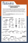
Tools Required ( Images are not to scale):
Safety Goggles
Drill #8 (1/8”)
Pencil
Phillips Screwdriver
Content ( Images are not to scale):
2x
Light Engine Unit
Safety Gloves
1x
Fixture Body
2 x Wire Nut
1x
Lanyard Screw
4x
Anchor
4x
Mounting Screw
Screw holes
Template
2
Operation
1- Carefully remove the fixture from packaging.
2- Turn power off at the fuse box before installing.
3- Determine the location of the fixture (refer to template) and
mark holes for attaching back plate to wall by using back plate
template.
4- Drill the hole through the center of the marks.
5- Place the anchors with the closed end evenly into the hole.
Gently tap the open end with a hammer or rubber mallet until the
anchor is almost flush with the wall.
6- Attach lanyard to electrical box with lanyard screw.
7- Pull wires from Electrical box and connect to wires from fixture
with wire nuts. Attach green ground wire following NEC code.
Black wire is line and white wire is neutral. Push wires into electrical box .
8- Place the fixture body over the wall and align the mounting
screw holes with the installed anchors. Insert mounting screws
and tighten them.
9- Take a light engine unit. Pull wires from light engine mount and
connect them to connector in light engine unit. Black to Black and
Red to Red.
10- Place the bayonet of the light engine unit in its place in the
light engine mount .
11- Twist the light engine unit counter clockwise. Repeat step 9
and 10 with rest of the light engine units.
12- Installation is complete. Turn on the power at the fuse box.
Turn light switch on to activate the fixture.
Lanyard
Mounting Plate
Light Engine Mount
Lever Nut
Light Engine
Shade
3
Step 7
Step 6
Step 8
Step 10
Step 9
Step 11
4
5 Year Limited Warranty
This product is warrantied by Beyond Limitations Lighting for defects in material and workmanship for a period of three
years from date of purchase. Contact Beyond Limitations Lighting for return directions. Product must be returned to the
manufacturing facility for repair and/or replacement along with proof of purchase. BL-Lights will repair or replace the
original light with replacement parts if needed and return the lamp back to you. In case the lamp is not repairable, a
replacement lamp will be shipped to you; this may be a refurbished lamp or a new lamp. This limited warranty does not
cover postage, freight, handling, insurance or delivery fees. This warranty does not cover damage, defect or failure caused
by/or resulting from accident, external destruction, alteration, modifications, abuse, misuse or misapplication of the product including fluctuating power levels.
BEYOND LIMITATIONS LIGHTING
LED Lighting
BL
BEYOND LIMITATIONS LIGHTING
5414 NE 148th Ave. Portland, OR, USA 97230
+1-503-261-1266
[email protected] | www.bl-lights.com
Designed and Printed in USA.
Copyright 2014 BL Lighting. All rights reserved.
5