1
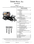
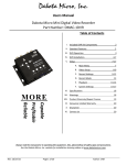
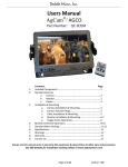
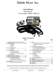
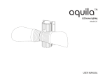
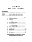
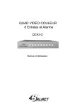
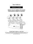
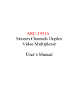
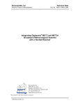
Dakota Micro, Inc. DMAC‐Q User Manual Users Manual Dakota Micro Quad Processor Part Number: DMAC‐Q MORE Capable Profitable Reliable Table of Contents Contents: I. Included Components II. Quad Processor Standard Features III. Installation a. Rear of Quad b. Video In/Out Cable c. Power/Trigger Input Cable IV. Quad Operation a. Quad Face Plate Buttons b. Monitor Face Buttons c. Remote Location Control Box V. Operation VI. Standard Quad Menu Settings a. System Setup b. Display Setup c. Time Setup d. Auto Sequence Time e. Camera Setup VII. Specifications VIII. Warning IX. Product Warranty/Repair Process X. Warranty XI. Disclaimer XII. Contact Us Page 2 2 3‐4 3 3 4 4‐5 4 5 5 6 6‐9 7 8 8 9 9 10 10 11 12 12 12 Always read the manual prior to operating this equipment. Also, please follow all safety signs and precautions. See the Dakota Micro, Inc. website for installation training videos at www.dakotamicro.com. Author: CNR Page 1 of 12 Dakota Micro, Inc. DMAC‐Q User Manual I. INCLUDED COMPONENTS Quad Kit Contents: 1. Quad Processor 2. Power/Trigger Input Cable 3. 12v Power Adaptor 4. Video In/Out Cable (for use ONLY w/ quad) 5. 1500mA A/C Power Adaptor 6. Remote location Control Box Thank you for purchasing the AgCam® Quad Processor. The AgCam® Quad is a full color, high resolution unit, which is 100% compatible with all Dakota Micro wired and wireless systems. II. QUAD PROCESSOR STANDARD FEATURES Fully compatible with all AgCam® components. View 1, 2 or 4 cameras at the same time. Up to 4 of your cameras can be wireless. Quad can be controlled from front of new style 7” & 9” monitors. Includes remote location control box. On‐screen display includes date & time. Adjust brightness, contrast, saturation, hue and sharpness for each camera. Individually mirror cameras. Supports both NTSC and PAL video formats. Camera priority settings. Easily output single or quad video signal to recorder. Full Quad display at real time refresh rate (60 fps). Page 2 of 12 Rev: 10/22/15 Dakota Micro, Inc. DMAC‐Q User Manual III. INSTALLATION A. Rear of Quad 1. 2. 3. 4. Camera Input/Video Output Cable Port (mates with #7 on Video In/Out Cable) VCR Input Port (RCA) VCR Output Port (RCA) Power/Trigger Input Port (Mates with #4 on Power/Trigger Input cable) b. Video In/Out Cable For use with Quad ONLY! Damage may occur if use is attempted with any other equipment. 1. 2. 3. 4. 5. 6. Camera 1 audio/video input. Camera 2 video input. Camera 3 video input. Camera 4 video input. Monitor output (plugs into port at bottom of associated models). USB control input for remote location control box or optional DM 7” & 9” monitors. Author: CNR Page 3 of 12 Dakota Micro, Inc. DMAC‐Q User Manual c. Power/Trigger Input Cable 1. Power IN (w/ inline replaceable 4amp fuse). 2. Camera Triggers (Trigger example: camera takes full screen when backing up). a. BROWN = Camera 1 trigger. b. BLUE = Camera 2 trigger. c. YELLOW = Camera 3 trigger. d. WHITE = Camera 4 trigger. 3. Power/Trigger Input connector. IV. QUAD OPERATION A. Quad Face plate Buttons Power Indicator Light (RED=OFF/GREEN=ON). POWER button turns your Quad ON/OFF. MENU button displays quad menu options on your monitor . AUTO button automatically cycles through available cameras (hold for 3 seconds). Quad view can be added from the menu. 5. MODE button toggles between split screen monitor views (cameras 1 and 2, cameras 3 and 4). 6. ENTER button allows users to select a chosen menu option. 7‐10. Brings cameras 1‐4 to full screen ‐AND‐ Up/Down & Left/Right for menu operations. 1. 2. 3. 4. Page 4 of 12 Rev: 10/22/15 Dakota Micro, Inc. DMAC‐Q User Manual b. Monitor Face Buttons 7” & 9” MONITOR‐ REMOTE QUAD OPERATIONS (7” model shown on left) 1 Full When connected to Quad will show Screen cameras 1/2/3/4 each time pressed. 2 Duplex When connected to Quad will show Screen camera 1 /2 and camera 3 /4 each time pressed. 3 Quad When connected to Quad will display all Screen four cameras connected. 4 Control USB female connector for Quad Plug processor (underside). c. Remote Location Control Box Kit Includes Remote location control box. Box functions are the same as above 1‐3 operations on 7” & 9” monitors. 7” & 9” MONITOR‐ REMOTE QUAD OPERATIONS 1 Full When connected to Quad will show Screen cameras 1/2/3/4 each time pressed. 2 Duplex Screen When connected to Quad will show cameras 1 /2 and cameras 3 /4 each time pressed. 3 Quad Screen When connected to Quad will display all four cameras connected. Author: CNR Page 5 of 12 Dakota Micro, Inc. DMAC‐Q User Manual V. OPERATION 1. Power on Quad by pushing the POWER button on the face of unit. 2. If you do not see video from your camera(s), try: a. Pushing the MODE button on the face of the Quad until you see your camera. b. Pushing the AV button on monitor or V1/V2 button on remote. Repeatedly pushing the AV button will cycle through the two video channels. VI. STANDARD QUAD MENU SETTINGS 1. Press and hold the MENU button for 3 seconds. 2. Use arrow buttons (7‐10 on photo of Quad face under “Quad Operations”) to select desired menu to adjust. 3. Use ENTER button (6 on Quad operation photo) to select desired option on any menu screen. 4. Use MENU button to exit out of any menu option. 5. Use and to move up and down through individual menu options. 6. Use and to change information on individual line items. Press and hold MENU button for 3 seconds to exit menu setup. Page 6 of 12 Rev: 10/22/15 Dakota Micro, Inc. DMAC‐Q User Manual a. System Setup DATE ........................................Set your current date. YEAR:MONTH:DAY TIME .........................................Set your current time. HOUR:MINUTE:SECOND SYSTEM FORMAT .....................Video system NTSC/PAL selectable. SYSTEM ID NUMBER ................Select unique ID # for Quad. KEY LOCK ..................................When set to ON position, only individual camera views available. When set to OFF position, all functions available. CAMERA PRIORITY ...................Selects which camera would have priority if more than one event trigger is set at the same time. For example if camera 1 and camera 3 triggers are both activated at the same time the event 1 trigger will take priority over the other. Only applies to the event triggers if used. VCR OUT ..................................Select type of image will be output for video out. POWER ON OUTPUT ................Selects the type of display image shown on power on. If set to OFF, Quad won’t automatically turn on when power is applied and POWER button will need to be pressed. FACTORY RESET .......................Restores unit to factory preset options. Author: CNR Page 7 of 12 Dakota Micro, Inc. DMAC‐Q User Manual b. Display Setup DISPLAY ON SCREEN ....................... Press ENTER to “Check” what information is displayed on screen. SCREEN POSITION ........................... X: moves screen to right, moves screen to left Y: moves screen up, moves screen down BORDER COLOR .............................. Press ENTER to select displayed border color. c. Time Setup Page 8 of 12 Rev: 10/22/15 Dakota Micro, Inc. DMAC‐Q User Manual d. Auto Sequence Time Auto sequence means the Quad box will show cameras 1,2,3&4 on full screen by turn. Default display time for each camera is one second. There are 2 ways to use the AUTO SEQUENCE function: 1) Press the AUTO key on Quad. 2) Press the key on the key board, the screen will show Quad view, then press again the screen will rotate between cameras 1‐4. HOLD TIME SETUP .......................... Hold time means the camera image delay time on the screen after the trigger wire operation is over. e. Camera Setup CAMERA ............................................................... Select cameras 1‐4 to adjust BRIGHTNESS ........................................................ Increases brightness Decreases brightness CONTRAST ........................................................... Increases contrast Decreases contrast SATURATION ........................................................ Increases saturation Decreases saturation HUE ...................................................................... Increases hue Decreases hue SHARPNESS .......................................................... Increases sharpness Decreases sharpness MIRRORING ......................................................... OFF=non mirrored ON=mirrored image Author: CNR Page 9 of 12 Dakota Micro, Inc. VII. DMAC‐Q User Manual SPECIFICATIONS Refresh Rate NTSC: 60fps/PAL: 50fps Resolution (HxV) NTSC: 860x525/PAL: 660x625 Power Input 9‐12VDC, 1200mA Environmental Rating IP50 Operating Temp ‐45°F~150°F (‐42°C~66°C) Video Freeze Duration 1‐99 Seconds Video Output Format Full/Quad/Freeze/Auto Switch Video Output Signal 1Vp‐75 Ohm CVBS out Video Output Port Switchcraftx1 Monitor Out, RCAx1 Video Out Video Input Port X4 cameras +1 VCR In Warranty 2 years VIII. WARNINGS When selecting a camera system from Dakota Micro, be sure to utilize the appropriate system for your use. AgCam and EnduraCam cameras are designed for high impact, moisture, vibration and a variety of other rough conditions. OverView cameras and kit components are designed for light use, low vibration and low moisture. OverView equipment is not warranted when used in situations outside of the above mentioned parameters. We always request that customers keep in mind that our less expensive OverView product line is cheaper because it does not feature the reliability and durability of our AgCam and EnduraCam lines. The warranty available on these products reflect that durability. To avoid electrical shock and maintain optimal functionality, do not open the enclosures. High voltage may be present and there are no user serviceable parts inside. All warranties will be void should any enclosures be tampered with in any way. Do not use any harsh chemical solvents, cleaning agents or corrosive detergent to clean away dirt on the surface of the screen or lens. On AgCam and EnduraCam products, the photo‐chromic camera lenses have been made impact‐resistant and have been drop‐ ball tested according to Sec. 3.84,21 CRF BUT ARE NOT UNBREAKABLE. Because they have been hardened chemically, they show no stress pattern. Inspect your lenses frequently. Chipped or scratched surfaces will reduce protection. Such lenses should be replaced only by the manufacturer. Power to cameras is not interrupted by turning off monitor; 12v power source must be terminated when not in use to avoid battery drain. To avoid this problem be sure when hard wiring a unit, use a fused circuit. Do not use your Dakota Micro camera system for anything other than legal surveillance and observation uses. Dakota Micro, Inc. is not liable for any illegal or nefarious usage. Page 10 of 12 Rev: 10/22/15 Dakota Micro, Inc. DMAC‐Q User Manual IX. PRODUCT WARRANTY/REPAIR PROCESS 1. 2. 3. For Technical Support call 1 866 462‐4226 OR email [email protected] Technician will assist in troubleshooting product malfunction. If product malfunction cannot be remedied and a repair is deemed necessary, Technician will issue a Repair Authorization (RA) number. IMPORTANT NOTE: The Technician will note on the RA form if the repair APPEARS to be a warranty or non‐warranty issue based on customer description of the issues at hand. No final determination can be made until inspection and testing of the equipment is completed at the factory. 4. To ensure fast and effective repairs, customer is required to send: Dakota Micro Product that Technician has requested/deemed necessary in the proper diagnosis and repair of malfunction. This may include some or all components of the kit. Original/Copy of purchase receipt. For serialized items ONLY; If a copy of the original purchase receipt cannot be provided, then DAKOTA MICRO will use the product manufacture date. Customer information, including return street addresses (NO PO Boxes) & phone number. If the phone number is not included, the customer will be sent a letter requesting the needed information. RA Number provided by Dakota Micro Technical Support Shipping and associated costs to ship product to DM factory to be borne by the customer unless otherwise specified. 5. Customer should mail product to: Dakota Micro, Inc. RA # XXXXX 8659 148th Ave. SE Cayuga, ND 58013 6. Upon receipt and evaluation of product at Dakota Micro Factory, it will be established if the repair is warranty or non‐ warranty. If requested, customer will be called and notified of any applicable charges. 7. If the repairs are deemed non‐warranty, and require a service/repair fee of any kind, a credit card number will be requested by Order Processing after the repair is completed. 8. If customer is unable to be contacted over the course of 3 weeks regarding required non‐warranty repairs, product will be returned, unrepaired, to the customer. 9. Any product returned without proper documentation may be returned at customer’s expense. 10. Product returned with unconfirmed problems will be assessed a $60 evaluation fee per unit 11. Return shipping costs will be borne by the party at fault; in other words, if Dakota Micro determines that the defective product was covered under warranty, Dakota Micro pays the shipping charges. If Dakota Micro determines that it was the customers fault, the customer will pay shipping charges. If a particular circumstance cannot be determined than the cost of shipping charges will be decided on a discretionary basis depending on the situation at hand. Author: CNR Page 11 of 12 Dakota Micro, Inc. DMAC‐Q User Manual X. CONSUMER LIMITED WARRANTY Subject to the disclaimer, limitations and other directions stated hereafter, Dakota Micro, Inc. warrants that the Product will be free from defects in material and workmanship for periods as stated hereafter from the date of original purchase. THIS WARRANTY IS EXPRESSLY MADE IN LIEU OF ANY AND ALL OTHER WARRANTIES, EXPRESS OR IMPLIED, INCLUDING THE IMPLIED WARRANTIES OF MERCHANTABILITY OR FITNESS. THE EXCLUSIVE REMEDY OF THE BUYER IS LIMITED TO REPAIR OR REPLACEMENT OF THE PRODUCT. EXCEPT AS STATED IN THIS WARRANTY, DAKOTA MICRO SHALL NOT BE LIABLE FOR ANY LOSS, INCONVENIENCE, OR DAMAGE, INCLUDING DIRECT, SPECIAL, INCIDENTAL, OR CONSEQUENTIAL DAMAGES, RESULTING FROM THE USE OR INABILITY TO USE THE PRODUCT, WHETHER RESULTING FROM BREACH OF WARRANTY, NEGLIGENCE, STRICT LIABILITY OF ANY OTHER LEGAL THEORY. Any oral statements or representations made by anyone which are contrary to or at variance with the terms stated in this LIMITED WARRANTY are void. Dakota Micro will, at its option, either repair the defect or replace the defective Product or part thereof with a new or remanufactured equivalent at no charge to the purchaser for parts or labor for the period of three (3) years for AgCam® cameras, two (2) years for AgCam® monitors, quads and Wireless Ranch Hands, Twelve Months (12) for all Overview Cameras & Monitors and one (1) year for Mini DVR, cables and all other accessories. The Dakota Micro limited warranty periods outlined above apply throughout the United States and Canada only. A one (1) year maximum limited warranty for all Products applies to all other geographic locations unless otherwise stated in writing by Dakota Micro. This limited warranty does not apply to any issues connected with appearance that have no relation to the performance of the Product nor to any Product the exterior of which has been damaged or defaced, which has been subjected to improper voltage or other misuse, abnormal service or handling, or which has been altered or modified in design or construction. In order to enforce the rights under this limited warranty, the purchaser should follow the steps set forth in the complete Dakota Micro “Warranty & Repair Policy” listed on page 11 ‐ section XVI , and provide proof of purchase to Dakota Micro. Neither the sales personnel of Dakota Micro nor any dealer or any other person is authorized to make any warranties other than those described herein, or to extend the duration of any warranties beyond the time periods described herein. The warranties described herein shall be the sole and exclusive warranties and remedies provided by Dakota Micro. Correction of defects, in the manner and for the period of time described herein, shall constitute complete fulfillment of all liabilities and responsibilities of Dakota Micro to the purchaser with respect to the Product, and shall constitute full satisfaction of all claims. In no event shall Dakota Micro be liable or in any way responsible for any damages or defects in the Product which were caused by repairs or attempted repairs performed by anyone other than Dakota Micro. Some states do not allow the limitation or exclusion of incidental or consequential damages, so said limitation may not apply to you. Any action at law, suit in equity, or other judicial proceeding for the enforcement of any right provided for herein or otherwise, or with respect to any claim that a purchaser may have against Dakota Micro shall be instituted only in the Courts of the State of North Dakota, either in the state district court located in Wahpeton, North Dakota or in Federal District Court location in Fargo, North Dakota. Without regard to conflicts of law principles, the laws of the state of North Dakota shall govern the interpretation and enforcement of the terms of this Limited Warranty and all aspects of the relationship between Dakota Micro and the purchaser. This warranty gives you specific legal rights and you may also have other rights, which may vary from state to state. XI. DISCLAIMER Dakota Micro Inc. products, specifications, pricing and programs are subject to change without prior notice. Dakota Micro Inc. reserves the right to make design changes at any time without obligation to retroactively install them on previously sold units. XII. CONTACT US Dakota Micro, Inc. 8659 148th Ave. SE. Cayuga, ND 58013 www.dakotamicro.com Page 12 of 12 Rev: 10/22/15