1
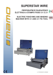
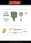
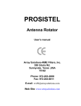
PRO. SIS. TEL.
Produzione sistemi telecomunicazioni
Antenna Rotator
User’s manual
C.da Conghia 298 - 70043 Monopoli BA Italy
Tel-Fax ++ 39 80 8876607
E-mail:[email protected]
Copyright ® PRO.SIS.TEL. 2000
Warning
This manual must be read carefully before proceeding to
assembly.
Warranty
1) The rotator with the control box, hereinafter called “The Product”, or “ The Rotator”, is
warranted for 2 years from date of purchase, provided that it is supported by the document of sale
issued by the manufacturer or authorized distributor.
2) The warranty includes free replacement or repair of any defective component.
3) This warranty does not cover misuse, negligence, accident, incorrect wiring, improper
installation, use contrary to instructions furnished by us, damage to units which have been repaired or
altered outside of our factory, or to injury or loss resulting from improper maintenance. The warranty
escludes damage caused by transport and all causes no arising from defects in workmanship.
4) The warranty does not includes the cost of trasport or insurance for material returned to our
workshops.
5) The manufactures is not responsible for personal injury, or property damage resulting from
improper usage of the product.
6) All product is tested after assembly and is supplied without defect. We exclude the
substitution or the prolongation of warranty for a possible damage.
7) After the 2 years warranty period, maintenance or repair will be subject to parts or labour
charges.
8) No person is authorized to assume for us any liability in connection with the sale of our
products.
9) This warranty excludes damage to people or property, arising from misure, improper or
careless installation, or disregard of instructions furnished by us.
10) The right of recession must be exercised in according to the law.
11) Our products are subject to continuous improvement. We reserve the right to effect changes
without notice.
12) The legal code applying in MONOPOLI, Italy, will apply, in cases of dispute.
13) Purchasers of product are deemed to accept paragraphs 1, 2, 3, 4, 5, 6, 7, 8, 9, 10, 11, 12
and 13 as above.
Model:
PST 641 - 2051
S/N:
Date of purchase:
2
Introduction
This manual contains instructions for installation, use and maintenance of the
P.S.T. 641 - 2051 antenna rotators.
Table of contents
Section 1:
Description;
Section 2:
Installation and use;
Section 3:
Principle of operation ;
Section 4:
Technical specifications.
Section 5:
Special functions
Note:
3
Section 1
Description
1.1 General
This manual cover installation on a mounting plate inside a tower or a rotator cage with a thrust
bearing.
The rotator consists of a rotator and a control box unit.
1.2 Unpacking and inspection
Be sure to check the rotator and control box after unpacking, especially if there is damage to the
carton.If damage is evident, you are advised to contact the carrier without delay.
1.3 The control box
FRONT PANEL- The power switch, the direction rotation switch, and the display that shows the
antenna position in degrees, are located on the front of panel.
REAR PANEL- The AC power supply socket, fuse holder, rotator control cable socket and DB 9
socket for remote control (i.e. computer interface or footswitch ), are located on the rear panel.
Fig. 2
4
1.4 The rotator
The rotator has a unique design. The motor is located on the side of a wormgeared motor.
The motor output shaft terminates on a flange, where different kinds of mast clamp, available
from us, may be fixed with bolts. Users may also supply their own clamp.
On the motor side is located a five-contact connector for motor power supply and potentiometer
terminals.
The potentiometer, used as the antenna position reader, is located inside the foot plate, and
driven by the transmission output shaft.
1.5 Accessories
The rotator is supplied with following accessories: AC power cable, plug for remote control
cable, standard mast clamp, steel bolts, and user manual.
T.W.
Rotor body
Motor
L.W.
Mast clamp
plate
S.W.
F.W.
Dimentions:
Height H
= cm - inch
Wide
F.W. = cm - inch
Wide
T.W. = cm - inch
Wide
L.W. = cm - inch
PST 641
15 - 6”
14 - 5” 1/2
24 - 9” 3/4
as F.W.
PST 2051
17 - 6” 3/4
16 - 6” 1/4
28 - 11”
as F.W.
Note 1: Dimentions may change without notice.
5
Section 2
Installation and wiring
2.1 Control cable preparation & connection
Before installing the rotator inside a tower, you need to prepare remote control cable, make all
connections and test rotator operation throughly on the ground, as described below.
Connect the rotator and control box with a 5-core control cable. Two cores are used for the
motor DC power supply, and three for the position reading potentiometer. If the diameter of the control
cable is too tinn, it will limit the voltage and reduce the torque. Do not use cable with less then .5 mm2
of section area.
Solder must be used to connect the individual cores to the 5 pin connector.
Cable plug
Wire no. 1
Wire no. 2
Wire no. 3
Wire no. 4
Wire no. 5
Motor terminals board
must be connected to
must be connected to
must be connected to
must be connected to
must be connected to
1 (VDC motor power)
2 (VDC motor power)
3 (P to pot central lead)
4 (- 12 Vdc pot lead)
5 (+ 12 Vdc pot lead)
Warning: Improper wiring can result in damage to the rotator
circuitry when the power is swiched on.
THIS IS NOT COVERED BY THE WARRANTY.
2.2 Inspection
Carefully check that the rotator and control box cable connections are as they should be before
turning on the power for the first time.
2.4 Pre-installation check (regural A box only)
The control box is supplied for 117 VAC (USA) or 220 VAC (EU) power supply. Without the
rotator control cable being connected, connect the power cable to the mains supply, and switch power
on. Display will show 000°. Switch power off and insert the control cable plug into the socket on control
box rear.
Switch power on and if all connections are correct, display will show about 000°. If a significantly
differerent value appears, switch the power off and check the control cable connections.
Push the direction lever in CW (clockwise) direction and the rotator will turn in the right or
clockwise direction.The display value will follow the rotator rotation. Continue until the CW elettronic
turn limit stop the motor rotation and display shows about 400°. Push the direction lever in the CCW
direction, and the rotator will turn left or counterclockwise.Continue until the CCW elettronic turn limit
stop the motor rotation and display shows about -040°. Move the rotator back to 000° by pushing the
direction lever in the CW direction, and switch power off.
2.5 Troubleshooting
A) Power
1) Check that the mains cable plugs are correctly connected.
2) Check the fuse. If it is blown, replace it with one of the correct value, and switch power on. If
it blows again, the user contacts the local service agent.
B) Motor turns in the wrong direction
1) Check the connections on motor terminals board.
2) Check the wiring of the control cable at both ends.
C) Motor turns correctly but display indicates the opposite
1) Wires no. 4/4 (-12 Vdc) and no. 5/5(+12 Vdc) are reversed.
D) When the rotator turned in the opposite direction, the turn limitation point is exceeded
1) Switch off at the control box. Disconnect the wire connected to P (pins 3-3) and connect a
6
voltmeter on 2 Vdc scale, between 3-3 pin (P) and ground. Switch on the control box and rotate the
rotator until the voltage on the voltmeter is about 0.1 volt, and reconnect wire to P.
E) Rotator turns but display show 000°: (regular A box only)
1) Check connection between pin-wire no.3 in control cable and 3 on motor terminal board.
2) Check connection between pins no. 4-4 and between pins no. 5-5.
3) Check -12 Vdc and +12 Vdc on pins 4-4 and 5-5
4) Check -12Vdc is on pin no. 4 and +12Vdc on pin no. 5 on control box socket.
5) Check the rotator potentiometer circuit. Disconnect the control cable plug from the socket and
check the resistence between pin no. 4 and pin no. 5. It should be 10 Kohm. Check the resistance
between pins no.3 and 4 and between pins no. 3 and 5, the values should be between 4 and 6 Kohm.
Their sum must to be 10 Kohm.
2.6 Control box adjustment (regular A box only)
All trimmers are set at the factory. To avoid problems, any adjustements should be made by
expert personnel and only if they are necessary. If this occurs in the warranty period this work must be
authorized in advance.
If the resistance of the control cable conductors is too high, the bearing value displayed may be
some degrees below the real antenna direction.
The bearing shown on control box indicator may be adjusted with trimmer no.1.
Turn the rotator till 000°, and with a pen make a mark between the rotator shaft and rotator
body. Turn the rotator in CW direction until marks align. If the bearing indicator does not dispay 360°,
using a small screwdriver slowly turn trimmer no. 1 until the indicator shows 360°.
The elettronic turn limitation may be changed with trimmer no. 3 for CCW limit and trimmer no. 2
for CW limit. Due to component tolerance, the indicated voltages may be slightly different.
The rotation limits are set as follows:
trimmer 2/pin 3 i.c. 4558 = - 0.123 v on -040°
trimmer 3/pin 6 i.c. 4558 = + 1.219 v on + 400°
( use digital voltmeter on 2V dc scale)
The rotation limits may also be approximately set without a digital voltmeter.
Turn rotor on 000°. This is the start line. Turn rotator CCW and at the same time, with a small
screwdriver, slowly turn trimmer 2 clockwise until the rotator stops. Adjust the trimmer in alternate
directions until the motor stops at -040°, or where you want it to stop. This is the left turn limit.
The same procedure applies to the right turn limit with trimmer no.3 turned in the
counterclockwise direction.
2.7 Installation
Before drilling holes in the mounting plate, place the rotator inside the tower and adjust its
placement so that there will be no interference between rotator body and tower.
Put the antenna mast inside the mast clamp and lock centrally. The centre axis line must be within
0.5° of true.
With a pen, mark the position of the mounting holes on the mounting place, remove the rotator, and
drill the holes .
Use the four bolts with washers and self-locking nuts to secure the rotator on the mounting plate.
Before tightening the bolts, insert the antenna mast in mast clamp, turn the rotator for 1 revolution
and adjust its position until the central axis line is within 0.5° . Now tighten the bolts.
2.8 Antenna direction adjustement
Antenna rotator alignment is mechanical. After the antenna is installed on the mast, turn rotator
to the desired direction, unlock the bolt on mast clamp, and with a magnetic compass turn the antenna
mast until the antenna beam direction is as shown on the rotator control box. Lock the antenna mast
with the mast clamp bolts. The antenna beam direction now is fixed. If you want to change it, you must
rotate the antenna clamp on antenna mast. If some more corrections are required, you can do it with
the trimmer TR7 within about 15 degrees for each side.
2.9 Rotator maintenance
The worm-geared motors are lubrificated for life and no maintenance is required. If you live in
an industrial zone or sea area, after a time you may have some corrosion to the outer casing. Rotators
are coated with anticorrosive paint at the factory, and if repainting is necessary, use ordinary
anticorrosive paint designed for ferrous metal.
2.10 Rotator control cable
As rotator control cable, you should use wires 1 and 2 having section no less than 1 mm2, if
7
your rotator cable is too long and you have too motor volts attenuatin along the line, you can increase
the motor voltage output. Remove the control box top cover, on the trasformer, there is a connector
with: 0-12-15-18-24, move the wire lead to new wanted connection.
Section 3
Principles of operation
3.1 Rotator
The rotator is manufactured with a worm-wheel geared motor drived by a high torque 12Vdc
motor.This method, normally used in heavy duty industrial and professional machinery, permits a very
high reduction ratio, with high power torque with both low power motor drive and high brake torque,
due the self-braking property of the worm-wheel geared motor.
3.2 Electrical configuration
3.2.1 Indicator circuit
Four digit, 7 segments led display are used for the direction indicator. This circuit is powered by
a separate D.C. power supply, and the antenna direction is displayed in degrees.
3.2.2 Turn limitation circuit (North stop)
The turn limitation circuit is powered by +12 Vdc and -12 Vdc and includes the potentiometer
located in the rotator base. Via terminal P, the antenna direction voltage is supplied to a double
operational amplifier used as comparator for CW turn limit and CCW turn limit. Trimmers no. 2 and 3
allow turn limits to be set.
3.2.3 Motor power switch
The motor is powered through two 10 Amps long life relais.
- 12 Vdc
+ 12 Vdc
power
15 Vac in
out
08 Vac in
- to display
+ to display
TR7
TR4
2
Turn
1 limitator
circuit
supply
TR5
d.c. amplifier
10A relay
10A relay
3
- 12
P
+ 12
U
Vdc motor power
Vdc motor power
Ground
Display
power supp.
ground
+ vdc display
- vdc display
v.p. display
ground
Display terminal board
ccw Motor Vac
in
cw
v.p. display
1 Trimmer v.p. display
2 Trimmer t.l. CCW
3 Trimmer t.l. CW
ccw
on
ground
off
on
cw
Direction switch
Fig. 3.2.4 Connections on printed circuit board.
8
Section 4
Specifications
4.1 Worm gear box
The worm gear box has a waterproof aluminium case conforms to the CEE 89/392/CEE
standard.
4.2 Motor
12Vdc motor in stell waterproof case conforms to CE standards.
4.3 Anticorrosive treatment
The rotator is painted with high resistence paint.
4.4 Control box
Case in hot painted steel.
Display tolerance: 1° after 5 minutes
Dimentions:
h = 13 cm,
w = 20 cm,
Weight: 3 kg
Power supply: 117/220 Vac 50 Hz 30 W
Conforms to applicable CE standards.
l = 21 cm
Specifications table
Mod.
PST 641
PST 2051
Wind load area (sq.ft)
16 or 1.2 m2
36 or 2.5 m2
Braking torque (in/lib)
4.840 or 5.500 kg/cm
10.800 or 12.500 kg/cm
Rotating torque (in/lbs)
528 or 600 kg/cm
1760 or 2000 kg/cm
Motor power Vdc
12
12
Rotation range
360° + and- 40° extra
360°+ and - 40° extra
Rotation speed for 360°
+ - 60”
+ - 60”
Control cable cores
5
5
Weight (rotator unit) lbs
+ - 88 or 4 Kg
+ - 13 or 6 Kg
Control box power Vac
117-230
117-230
Note: Specifications may be changed without notice.
9
Section 5
Special functions
5.1 Remote control
The DB9 socket located on control box rear panel allows the remote control of the rotator via
computer interface or foot-switch.
5.2 Computer compatible (A box only)
The rotator remote control had been tested and works well with the following computer
interfaces: SARtek1 , ARS , Trak box.
The output voltage is available on pin no. 7 and may be set with trimmer TR5 from 2 to10 DC
volts and used to drive any computer interface.
Check the voltage limits of the computer interface gate before connecting it to the remote
control socket.
Output voltage is factory-set at 5 Vdc, to corrispond to a 360° rotator position.
5.3 DC amplifier
A variable DC amplifier is used to increase the antenna direction voltage level.
This circuit is located on main printed circuit board close to the motor capacitor.
5 4 3 2 1
DC amplifier
TR4
TR5
1
IC
8
9 8 7 6
1- 5 = not used.
6 = ground
7 = antenna direction output voltage " P"
8 = CW
9 = CCW
To adjust, turn rotator to 000°, connect a digital voltmeter with 200 mV scale between pin 7 and
ground. If you don’t read 0V, using a small screwdriver, turn TR4 to read 0V. Turn rotator to 360°,
switch voltmeter to 20 V scale and rotate TR5 until the voltage required by the computer interface is
present.
To prevent damage to the computer interface, we suggest that the left rotator turn limit is set to
000°.
Dear customer, thank you for purchasing of the our rotators.
If you are satisfied with it, tell to other people ,
if you are not satisfied with it, please talk to us!
MADE IN ITALY
10