1
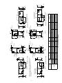
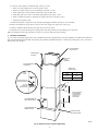
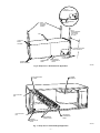
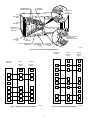
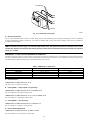
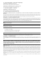
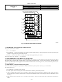
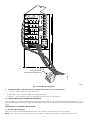
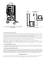
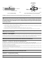
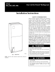
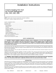
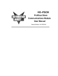
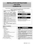
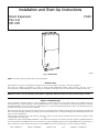
Installation and Start-Up Instructions
Direct Expansion
Fan Coil
001-006
FK4C
A92500
Fig. 1—Model FK4C
NOTE: Read entire instruction manual before starting installation.
INTRODUCTION
Model FK4C Fan Coil Units are designed for flexibility and can be used for upflow, horizontal, or downflow applications.
These units are available for application in systems of 18,000 through 60,000 Btuh nominal cooling capacities. (See Fig. 2 and 3.)
Factory-authorized, field-installed electric heater packages are available in 5 through 30 kw. See product data for available accessory kits.
WARNING: Before installing or servicing fan coil, always turn off all power to unit. There may be more than 1
disconnect switch. Turn off accessory heater power if applicable. Electrical shock can cause personal injury or death.
SAFETY CONSIDERATIONS
Improper installation, adjustment, alteration, service, maintenance, or use can cause explosion, fire, electrical shock or other conditions which may
cause personal injury or property damage. Consult a qualified installer, service agency, or your distributor or branch for information or assistance.
The qualified installer or agency must use factory-authorized kits or accessories when modifying this product. Refer to the individual instructions
packaged with the kits or accessories when installing.
Follow all safety codes. Wear safety glasses and work gloves. Use quenching cloth for brazing operations. Have fire extinguisher available. Read
these instructions thoroughly and follow all warnings or cautions attached to the unit. Consult local building codes and National Electrical Code
(NEC) for special requirements.
. When you see this symbol on the unit and in instructions or manuals, be alert
Recognize safety information. This is the safety-alert symbol
to the potential for personal injury.
Understand the signal word DANGER, WARNING or CAUTION. These words are used with the safety-alert symbol. DANGER identifies the
most serious hazards which will result in severe personal injury or death. WARNING signifies hazards which could result in personal injury or
death. CAUTION is used to identify unsafe practices which would result in minor personal injury or product and property damage.
Form:
IM-FK4C-01
Cancels:
IM-FK4B-02
Printed in U.S.A.
8-95
Catalog No.
92-33FK-4C1
—2—
5″
INLET AIR
OPENING
F
C
B
TOP VIEW
FILTER ACCESS PANEL
63/16″
SUCTION LINE
CONNECTION
FITTING PANEL
SIZE
001
002
003
005
006
UNIT
FK4C
A
In.
47-5/8
42-11/16
53-7/16
53-7/16
59-3/16
91/4″
213/16″
411/16″
C
In.
15-3/4
15-3/4
19-1/4
19-1/4
22-3/4
G
INLET AIR
D
In.
—
14-1/4
—
14-15/16
17-13/16
DOWNFLOW APPLICATIONS
“A” COILS
DOWNFLOW OR HORIZ
RIGHT APPLICATIONS
AND
ACCESS PANEL CONFIG
FOR SLOPE COILS
LIQUID LINE
CONNECTION
Fig. 2—Dimensional Drawing
B
In.
17-5/8
17-5/8
21-1/8
21-1/8
24-11/16
CONNECTION LOCATIONS SHOWN
FOR UPFLOW OR HORIZ
LEFT APPLICATIONS
SLOPE COIL DETAILS
LIQUID LINE
CONNECTION
SUCTION LINE
CONNECTION
E
In.
23-3/16
18-3/16
27
27
32-11/16
OPTIONAL FIELD CONVERTED
RIGHT SIDE RETURN OPENING
(SLOPE COIL UNITS ONLY)
A
11/4″
11/16″
11/4″
21/8″
ALTERNATE
7/8″ DIA K.O.
FOR LOW VOLTAGE
CONTROL WIRING
11″
OUTLET AIR
221/16″
F
In.
16
16
19-1/2
19-1/2
23
A95310
G
In.
15-3/8
10-3/4
19-3/16
19-1/2
25-1/4
INLET AIR
RIGHT SIDE VIEW
201/16″
OPENING
19″
11/2″
ALTERNATE
7/8″, 1 3/32″, 2.0″ DIA K.O.'S
FOR HIGH VOLTAGE POWER
WIRING OPPOSITE SIDE
1″
103/16″
1. ALLOW 21.0″ FROM FRONT FOR SERVICE.
2. UNITS WITH 20, 24 AND 30 K.W. HEATERS MUST MAINTAIN
A MINIMUM OF 1.0″ CLEARANCE FROM DISCHARGE
DUCT CLEARANCE TO COMBUSTIBLE MATERIALS.
3. WHEN INSTALLED OVER FINISHED CEILING/LIVING SPACE
A FIELD SUPPLIED SECONDARY CONDENSATE PAN MUST BE INSTALLED.
NOTES:
CONDENSATE PAN CONNECTIONS: 3/4″ FPT UPFLOW/DOWNFLOW
HORIZ A-COILS: 3/4″ FEMALE PVC GLUE JOINT
VIA FITTINGS PROVIDED.
UNIT CONNECTION SIZES
SUCTION: 001 & 002 - 3/4″ I.D. SWEAT
003, 005 & 006 7/8″ SWEAT
LIQUID: 3/8″ I.D. SWEAT
103/4″
LIQUID LINE CONNECTION
COIL ACCESS
PANEL
BLOWER, CONTROL,
& ELECTRIC HEATER
ACCESS PANEL
DISCONNECT OR
CIRCUIT BREAKER
LOCATION
13/8″
(34.9)
7/8″, 1 3/32″ & 2.0″DIA
FOR HIGH VOLTAGE POWER WIRING
1″
FRONT VIEW SHOWN WITH “A” COIL DETAILS
CONNECTION LOCATIONS FOR UPFLOW OR HORIZ APPLICATIONS
3/4″
107/16″
25/8″
15/16″
115/16″
17/8″
FOR LOW VOLTAGE
CONTROL WIRING
7/8″ DIA K.O.
L
K
21/2″
FOR
MODULAR
UNITS
MAX
MODULAR
UNITS WILL
HAVE A TWOPIECE CABINET
NOTE:
3/4″
7/8″
—3—
11/2″
HORIZ LEFT
SLOPE COIL
E
11/2″
16″
TYP✽
5/
APPLICATION: AS SHIPPED
31/8″
SECONDARY DRAIN
2″
TYP✽
1/
13/
8″
PRIMARY DRAIN
16″
TYP✽
5/
001
002
003
005
006
FK4C
3″
J
In.
23-1/2
18-1/8
27-3/8
26-15/16
32-5/8
In.
23
18-7/16
26-13/16
27-1/4
32-15/16
UPFLOW
A–COIL
43/4″
31/8″
AIRFLOW
UPFLOW
SLOPE COIL
11/2″
H
TYP
(2 PLACES)✽
2 3/16″
PRIMARY
DRAIN
SECONDARY
DRAIN
APPLICATION: AS SHIPPED
SIZE
E
D
TYP✽
113/16″
UNIT
HORIZ LEFT
A–COIL
SECONDARY DRAIN
(INSTALL SPECIAL
DAM FITTING)
2 3/16″
TYP
(2 PLACES)✽
SECONDARY
DRAIN
MOUNT LOCATIONS – DIMPLES PROVIDED IN TOP PANEL,
AND BACK OF CABINET. IN CABINET BOTTOM, HOLES PROVIDED
0.136″ DIA. HORIZONTAL HANGING HARDWARE TO BE
FIELD SUPPLIED.
✽ HORIZONTAL
8″
7/ ″
8
TYP✽
7/
2″
TYP✽
1/
PRIMARY DRAIN
TYP✽
113/16″
PRIMARY
DRAIN
AIRFLOW
1″
16″
TYP
(4 PLACES)✽
7/
In.
—
—
—
—
34-1/16
K
11/2″
3″
31/8″
In.
17
—
19
—
—
L
TYP
(2 PLACES)✽
1″
SECONDARY
DRAIN
PRIMARY
DRAIN
H
43/4″
TYP
(2 PLACES)✽
1″
PRIMARY
DRAIN
SECONDARY
DRAIN
H
AIRFLOW
J
J
11/2″
5/ ″
16
TYP✽
Slope
Yes
—
Yes
—
—
H
215/16″
5/ ″
16
TYP✽
D
E
13/8″
"A"
—
Yes
—
Yes
Yes
OPERATING
WEIGHT
lb
112
120
145
162
195
A95311
HORIZ RIGHT
A–COIL
15/16″
7/ ″
8
TYP✽
1/ ″
2
TYP✽
SECONDARY DRAIN
(INSTALL SPECIAL
DAM FITTING)
PRIMARY DRAIN
APPLICATION: FIELD CONVERTED
TYP✽
113/16″
2 3/16″
TYP
(2 PLACES)✽
HORIZ RIGHT
SLOPE COIL
1/ ″
2
TYP✽
SECONDARY DRAIN
11/2″
PRIMARY DRAIN
APPLICATION: FIELD CONVERTED
TYP✽
113/16″
2 3/16″
TYP
(2 PLACES)✽
COIL CONFIGURATION
DOWNFLOW
A–COIL
16″
TYP
(4 PLACES)✽
7/
AIRFLOW
DOWNFLOW
SLOPE COIL
7/ ″
16
TYP
(4 PLACES)✽
Fig. 3—Dimensional Drawing
211/16″
3″
TYP
(2 PLACES)✽
1″
25/8″
31/8″
TYP
(2 PLACES)✽
7/ ″
16
TYP
(4 PLACES)✽
7/ ″
8
TYP✽
INSTALLATION
PROCEDURE 1—CHECK EQUIPMENT
Unpack unit and move to final location. Remove carton taking care not to damage unit.
Inspect equipment for damage prior to installation. File claim with shipping company if shipment is damaged or incomplete. Locate unit rating
plate which contains proper installation information. Check rating plate to be sure unit matches job specifications.
PROCEDURE 2—MOUNT FAN COIL
Unit can stand or lie on floor, or hang from ceiling or wall. Allow space for wiring, piping, and servicing unit.
IMPORTANT: When unit is installed over a finished ceiling and/or living area, building codes CABO M-1701.2, UMC 1205, SBCCI 603.4 may
require a field-supplied secondary condensate pan to be installed under the entire unit. Some localities may allow as an alterative the running of
a separate, secondary condensate line. Consult local codes for additional restrictions or precautions.
When installing any fan coil over a finished ceiling and/or living area, installation of a secondary drain pan under entire unit to avoid damage to
ceiling is recommended.
The FK4C Fan Coils can be installed for upflow and horizontal-left applications as factory shipped. Units can be installed for horizontal-right
applications with field modifications. Units may be converted for downflow applications using factory-authorized accessory kit.
NOTE: To ensure proper drainage for horizontal installations, unit must be installed so it is within 1/8 in. level of the length and width of unit.
A. Upflow Installation
If return air is to be ducted, install duct flush with floor. Set unit on floor over opening.
Only use return-air opening provided. All return air must pass through the coil. (See Fig. 4.)
B. Modular Units
The FK4C fan coil in size 006 is a 2 piece modular unit. Modular construction allows installer to disassemble unit into 2 components, coil box
and blower box, for ease of installation. (See Fig. 5.)
To disassemble unit, remove rear corner brackets by removing 2 screws which secure brackets. (See Fig. 5.) Remove either 2 screws in each front
corner of coil box, or 2 screws in blower box. Do not remove all 4 screws in each corner. (See Fig. 5.) Sections may now be separated by lifting
top section from lower section.
To reassemble, reverse above procedure. Be certain to reinstall all fasteners when reassembling.
C. Horizontal Installations
Be sure installation complies with all applicable building codes that may require installation of a secondary condensate pan.
1. Arrange support for unit by setting it in or above secondary condensate pan.
2. When suspending unit from ceiling, dimples in casing indicate proper location of screws for mounting metal support straps. (See Fig. 6.)
CAUTION: For optimum condensate drainage performance in horizontal installations, unit should be leveled along its
lingth or raised 1/4-in. at the air inlet. The unit should also be pitched forward 1/4-in. to 1/2-in. toward the front condensate
drains.
D. Horizontal-Right Conversion of Units with Slope Coils
To convert units for horizontal right installations:
1. Remove blower and coil access panels and fitting panel. (See Fig. 7.)
2. Remove screw securing coil assembly to right side casing flange.
3. Remove coil assembly.
4. Lay fan coil on its right side and reinstall coil assembly with condensate pan down. (See Fig. 7.)
5. Attach coil to casing flange using previously removed coil mounting screw.
6. Reinstall access panels and fitting panel, aligning holes with tubing connections and condensate pan connections.
Make sure liquid and suction tube grommets are in place to prevent air leaks and cabinet sweating. Install grommets after brazing.
E. Horizontal Right Conversion of Units With A-Coil
To convert units for horizontal right installations:
1. Remove blower and coil access panels. (See Fig. 8.)
2. Remove fitting door clip to plastic condensate pan and remove fitting door.
3. Remove snap-in shipping clip securing A-coil in unit.
4. Remove coil assembly.
5. Remove metal horizontal drain pan from coil assembly.
6. Remove horizontal drain pan support bracket from coil support rail and reinstall coil support rail on the opposite side.
7. Remove condensate drain plugs from 1 side of horizontal drain pan and install in drain connection openings on opposite side.
—4—
8. Convert air seal assembly for horizontal right. (See Fig. 8, inset.)
a. Remove air-seal assembly from coil by removing 4 screws.
b. Remove air splitter (B) from coil seal assembly by removing 3 screws.
c. Remove filler plate (A) and install air splitter (B) in place of filler plate.
d. Install filler plate (A) as shown in horizontal right application (See Fig. 8, inset.)
e. Remove condensate troughs (C) and install on opposite tube sheets. (See Fig. 8 insets.)
f. Install hose onto plastic spout.
9. Install horizontal pan on right side of coil assembly with plugged condensate openings to rear of assembly.
10. Slide coil assembly into casing. Be sure clips on each corner engage coil support rails. (See Fig. 8.)
11. Remove condensate drain knockouts from right side of coil access panel.
12. Reinstall access panels and fitting door, aligning holes with tubing connections and condensate pan connections.
Make sure liquid and suction tube grommets are in place to prevent air leaks and cabinet sweating.
F.
Downflow Installations
To convert units for downflow applications, refer to Installation Instructions supplied with kit for proper installation. For FK4C unit sizes 001 and
002, use kit KFADC0201SLP. For FK4C unit sizes 003, 005, and 006 use kit KFADC0301ACL. Use fireproof resilient gasket, 1/8- to 1/4-in. thick,
between duct, unit, and floor.
FIELD SUPPLIED
SUPPLY DUCT
POWER ENTRY
OPTIONS
LOW VOLT
ENTRY
OPTIONS
24″ FRONT SERVICE
CLEARANCE
SLOPE COIL
SIDE RETURN
A COIL
UNITS
UPFLOW/DOWNFLOW
SECONDARY DRAIN
UNIT
A
001
17-in.
003
19-in.
1 1/2″
UPFLOW/
DOWNFLOW
PRIMARY DRAIN
19″
A
FIELD MODIFIED
SIDE RETURN
LOCATION FOR
SLOPE COIL
UNITS ONLY
UPFLOW/DOWNFLOW
SECONDARY DRAIN
2 1/2″
UPFLOW/DOWNFLOW
PRIMARY DRAIN
FIELD SUPPLIED
RETURN PLENUM
A93096
Fig. 4—Slope Coil Unit in Upflow Application
—5—
BLOWER BOX
2 SCREWS
2 SCREWS
REAR CORNER
BRACKET
2 SCREWS
COIL BOX
A90168
Fig. 5—Modular Unit Assembly
PROCEDURE 3—AIR DUCTS
Connect the supply-air duct over outside of 3/4-in. flange provided on supply-air opening. Secure duct to flange with proper fasteners for type of
duct used, and tape duct-to-unit joint.
Duct connection flanges are provided on unit air discharge connection.
When using FK4C units with 20-, 24-, and 30-kw electric heaters, maintain a 1-in. clearance from combustible materials to discharge plenum and
ductwork for a distance of 36 in. from unit. Use an accessory downflow base to maintain proper clearance on downflow installations.
Use flexible connectors between ductwork and unit to prevent transmission of vibration. When electric heater is installed, use heat resistant material
for flexible connector between ductwork and unit at discharge connection. Ductwork passing through unconditioned space must be insulated and
covered with vapor barrier.
A. Ductwork Acoustical Treatment
Metal duct systems that do not have a 90° elbow and 10 ft of main duct to first branch takeoff may require internal acoustical insulation lining.
As an alternative, fibrous ductwork may be used if constructed and installed in accordance with the latest edition of SMACNA construction
standard on fibrous glass ducts. Both acoustical lining and fibrous ductwork shall comply with National Fire Protection Association as tested by
UL Standard 181 for Class 1 air ducts.
PROCEDURE 4—ELECTRICAL CONNECTIONS
A. Line Voltage Connections
Units with 15-, 20-, 24 and 30-kw heaters are factory wired for dual-circuit operation. When single-circuit operation is required, install
factory-authorized adapter kit for fused models only.
Check all factory wiring per unit wiring diagram and inspect factory wiring connections to be sure none were loosened in transit or installation.
WARNING: Before installing or servicing system, always turn off all power to system. There may be more than 1
disconnect switch. Turn off accessory heater power if applicable. Electrical shock can cause personal injury or death.
CAUTION: If a disconnect switch is to be mounted on the unit, select a location where drill or fastener will not contact
electrical or refrigerant components. Electrical shock can cause personal injury or death.
NOTE: Before proceeding with electrical connections, make certain that supply voltage, frequency, and phase are as specified on unit rating plate.
Be sure that electrical service provided by the utility is sufficient to handle the additional load imposed by this equipment.
See unit wiring label for proper field high- and low-voltage wiring. Make all electrical connections in accordance with NEC and any local codes
or ordinances that may apply. Use copper wire only. The unit must have a separate branch electric circuit with a field-supplied disconnect switch
located within sight from, and readily accessible from the unit.
—6—
A-COIL IN
HORIZONTAL LEFT
SECONDARY
PRIMARY
FIELD
SUPPLIED
HANGING
STRAPS
24-IN.
FRONT SERVICE
CLEARANCE
(FULL FACE
OF UNIT)
UNIT
LOW VOLT
ENTRY
OPTIONS
OPTIONAL RETURN
AIR FLANGE KIT
PRIMARY
CONDENSATE
DRAIN
POWER
ENTRY OPTIONS
SECONDARY
CONDENSATE
DRAIN
1 3/4 IN.
FILTER ACCESS
CLEARANCE
A90167
Fig. 6—Slope Coil in Horizontal-Left Application
COIL MOUNTING
SCREW
BLOWER
ASSEMBLY
COIL SUPPORT
RAIL
COIL SUPPORT
RAIL
REFRIGERANT
CONNECTIONS
SECONDARY
CONDENSATE
DRAIN
PRIMARY
CONDENSATE
DRAIN
A90174
Fig. 7—Slope Coil in Horizontal-Right Application
—7—
A
REFRIGERANT
CONNECTIONS
AIR SEAL
ASSEMBLY
HORIZONTAL
RIGHT
APPLICATION
COIL
SUPPORT
RAIL
B
C
COIL
BRACKET
DRAIN PAN
SUPPORT
BRACKET
A
COIL
SUPPORT
RAIL
FACTORY SHIPPED
HORIZONTAL
LEFT APPLICATION
COIL
BRACKET
METAL HORIZONTAL
DRAIN PAN
SECONDARY
CONDENSATE
DRAIN
PRIMARY
CONDENSATE
DRAIN
B
C
A91119
Fig. 8—A-Coil in Horizontal Right-Application
FK4C
Outdoor
Terminal
Block
Terminal
Board
W2
W3
C
C
C
W/
W1
W1
W2
Thermostat
Subbase
FK4C
Outdoor
Terminal
Block
Terminal
Board
W2
W3
C
C
C
L
W/
W1
W1
W2
G
G
G
Y/Y2
Y/Y2
Y2
Y1
/W2
Y1
Y1
Thermostat
Subbase
L
G
G
G
Y/Y2
Y/Y2
Y
O/W
2
O
O
O/W
2
O
O
R
R
R
R
R
R
E
A95313
A95314
Fig. 9—Single-Speed Heat Pump Wiring
Fig. 10—Two-Speed Heat Pump Wiring
—8—
THERMOSTAT
TERMINAL
BLOCK
EASY SELECT
OUTDOOR UNIT
BOARD TERMINAL
TERMINAL
BLOCK
BLOCK
L
L
R
R
R
C
C
C
O⁄W2
O
O
Y⁄Y2
Y⁄Y2
Y
Y1
G
G
E
W⁄W1
W1
W2
Y1⁄W2
W2
W3
EASY
SELECT
BOARD
JUMPER J2.
A95315
Fig. 11—Single Speed Heat Pump Wiring with Intelligent Heat Staging
B. 24-V Control System Connections to Unit Printed-Circuit Board (PCB)
Refer to unit wiring instructions for recommended wiring procedures. Use No. 18 AWG color-coded, insulated (35C° minimum) wires to make
low-voltage connections between thermostat and unit. If thermostat is located more than 100 ft from unit (as measured along the low-voltage
wires), use No. 16 AWG color-coded, insulated (35°C minimum) wires. PCB is circuited for single-stage heater operation. When additional heater
staging is desired using 2-stage or outdoor thermostats, see applicable outdoor unit instructions. Remove Jumper J2 on PCB.
1. The 5-, 8-, and 10-kw heaters are single stage only.
2. The 15- and 20-kw heaters are adaptable for 2-stage operation.
3. The 24- and 30-kw heaters are adaptable for up to 3-stage operation.
Connect low-voltage leads to thermostat and outdoor unit. (See Fig. 9 and 10.)
C. Intelligent Heat Staging Option
Intelligent staging of the electric heat package is possible when the FK4C is installed as a part of a single-speed heat pump system using a corporate
2-speed programmable thermostat and any one of the electric heat packages 9kw, 15kw, 24kw, or 30kw.
To activate intelligent staging, the intelligent staging switch in thermostat must be set and W1-W2 jumper (J2) must be removed. Complete system
low-voltage wiring as shown in Fig. 11. Do not use outdoor thermostats when using intelligent heat staging.
NOTE: Where local codes require thermostat wiring be routed through conduit or raceways, splices can be made inside the fan coil unit. All
wiring must be NEC Class l and must be separated from incoming power leads.
A factory-authorized disconnect kit is available for installation of 0- through 10-kw applications. When electric heat packages with circuit breakers
are installed, the circuit breaker can be used as a disconnect.
NOTE: Transformer is factory wired for 230v operation. For 208v applications, disconnect black wires from 230v terminal on the transformer
and connect them to the 208v terminal. (See Fig. 12.)
The secondary circuit of the transformer is protected by a 5-amp fuse mounted on the printed-circuit board.
—9—
SECONDARY
YEL
BLK
230
208
C
BRN
RED
PRIMARY
A94067
Fig. 12—Transformer Connections
D. Ground Connections
Use UL listed conduit and conduit connector to connect supply wire(s) to unit and obtain proper grounding. Grounding may also be accomplished
by using grounding lug provided in control box. Use of dual or multiple supply circuits will require grounding of each circuit to ground lugs
provided on unit and heaters.
WARNING: The cabinet must have an uninterrupted or unbroken ground according to NEC, ANSI/NFPA 70 and local
codes to minimize personal injury if an electrical fault should occur. The ground may consist of electrical wire or metal
conduit when installed in accordance with existing electrical codes. Failure to follow this warning could result in an electrical
shock, fire, or death.
PROCEDURE 5—FK4C FAN COIL SEQUENCE OF OPERATION
The FK4C will supply airflow in a range which is more than twice the range of a standard fan coil. It is designed for nominal cooling capacities
at a 50°F evaporator temperature and to provide the required airflow which enables it to match with 4 air conditioner or heat pump system sizes.
The following table outlines the CFM range for the different FK4C fan coil sizes.
Table 1–CFM Range for FK4C Units
FAN COIL SIZE
FK4CNF001
FK4CNF002
FK4CNF003
FK4CNB005
FK4CNB006
A.
SYSTEM SIZES
018, 024, 030, 036
018, 024, 030, 036
024, 030, 036, 042
030, 036, 042, 048
036, 042, 048, 060
Continuous Fan
THERMOSTAT CLOSES CIRCUIT R TO G
The blower runs at continuous fan airflow.
B.
Cooling Mode — Single speed or 2 speed high
THERMOSTAT CLOSES CIRCUITS R TO Y/Y2 AND R TO O
The fan coil delivers single speed cooling airflow.
THERMOSTAT CLOSES CIRCUIT R TO Y1, R TO Y2 AND R TO O
The fan coil delivers 2 speed high cooling airflow.
C.
Cooling Mode — Two speed low
THERMOSTAT CLOSES CIRCUITS R TO Y1 AND R TO O
The fan coil delivers 2-speed low cooling airflow.
D.
Electric Heat Heating Mode
THERMOSTAT CLOSES CIRCUIT R TO W/W1, OR W2
The fan coil delivers the selected electric heat airflow.
—10—
CFM RANGE
450-1275
450-1275
525-1475
550-1700
550-2150
E.
Heat Pump Heating Mode — Single speed or 2-Speed High
THERMOSTAT CLOSES CIRCUIT R TO Y/Y2
The fan coil delivers single speed heat pump heating airflow.
THERMOSTAT CLOSES CIRCUIT R TO Y1 AND R TO Y/Y2
The fan coil delivers 2 speed high heat pump heating airflow.
F.
Heat Pump Heating Mode — 2-speed low
THERMOSTAT CLOSES CIRCUIT R TO Y1
The fan coil delivers 2-speed heat pump heating low airflow.
G.
Heat Pump Heating with Auxiliary Electric Heat
THERMOSTAT CLOSES CIRCUITS R TO Y/Y2 AND/OR R TO Y1 WITH R TO W/W1 OR W2 (AND R TO O IN THE CASE OF
DEFROST)
In the event that electric heating is called for by the thermostat while the heat pump is also operating in either heating or defrost modes, the motor
will modify its airflow output, if necessary, to provide an airflow which is defined as safe for the operation of the electric heater during heat pump
operation. That airflow is the greater of the heat pump heating airflow and the greater of the electric heater only airflow.
PROCEDURE 6—CONNECT REFRIGERANT TUBING
See Dimensional Drawing for tube connection sizes, type, and locations. Use accessory tubing package or field-supplied tubing of refrigerant
grade. Insulate entire suction tube if field-supplied tubing is used. Tubing package has an insulated suction tube. Do not use damaged, dirty, or
contaminated tubing because it may plug refrigerant flow control device. When tubing package is used and sweat connections are made within
60 sec, coil and tubing system does not require evacuation. Always evacuate if field-supplied tubing is used.
CAUTION: A brazing shield MUST be used when tubing sets are being brazed to the unit connections to prevent
damage to the unit surface.
CAUTION: To prevent damage to thermostatic expansion valve, remove sensor bulb from vapor tube while brazing or
soldering vapor connections.
Units have sweat suction and liquid tube connections. Make suction tube connection first.
1. Cut tubing to correct length.
2. Insert tube into sweat connection on unit until it bottoms.
3. Solder with low-temperature 430° F silver alloy solder.
CAUTION: Wrap a wet cloth around rear of fitting to prevent damage to factory-made joints.
4. Evacuate coil and tubing system if connections are not made within 60 sec or tubing package is not used.
PROCEDURE 7—CONDENSATE DRAIN
Units are equipped with primary and secondary 3/4-in. FPT drain connections. Use a 3/4-in. glue joint with fittings provided for units with A-coils
in horizontal applications. It is recommended that PVC fittings be used on the plastic condensate pan. Do not over-tighten. Finger-tighten plus 1-1/2
turns.
CAUTION: To prevent property damage and achieve optimum drainage performance, BOTH primary and secondary
drain lines should be installed and include properly-sized condensate traps. (See Fig. 13.) Shallow running taps are
inadequate and DO NOT allow proper condensate drainage. (See Fig. 14.) For horizontal installations of units with A-coils,
use plastic fittings provided. (See Fig. 15.) Make sure that the correct plastic fitting is installed in the correct location on the
horizontal drain pan. Use pipe dope.
NOTE: When connection condensate drain lines avoid blocking filter access panel. Prime both primary and secondary condensate traps after
connecting to drain pan.
NOTE: If unit is located in or above a living space where damage may result from condensate overflow, a field-supplied external condensate pan
should be installed underneath the entire unit, and a secondary condensate line (with appropriate trap) should be run from the unit into the pan.
Any condensate in this external condensate pan should be drained to a noticeable place. As an alternative to using an external condensate pan, some
localities may allow the running of a separate 3/4-in. condensate line (with appropriate trap) to a place where the condensate will be noticeable.
The owner of the structure must be informed that when condensate flows from the secondary drain or external condensate pane, the unit requires
servicing, else water damage will occur.
Install traps in the condensate lines as close to the coil as possible. (See Fig. 16.) Make sure that the outlet of each trap is below its connection
to the condensate pan to prevent condensate from overflowing the drain pan. Prime all traps, test for leaks, and insulate traps if located above a
living are.
Condensate drain lines should be pitched downward at a minimum of 1-in. for every 10 ft. of length. Consult local codes for additional restrictions
or precautions.
—11—
UNIT
DO NOT USE SHALLOW RUNNING TRAPS!
2 1⁄4″
A95320
Fig. 14—Insufficient Condensate Trap
2 1⁄4″
A95321
Fig. 13—Recommended Condensate Trap
SECONDARY
(TRAP REQUIRED)
S
PRIMARY
2 1/4-IN. MIN
2 1/4-IN. MIN
SECONDARY FITTING
WITH BUILT IN DAM
PRIMARY FITTING
A90347
FILTER
ACCESS
PANEL
A90173
Fig. 16—Condensate Trap and Unit
Fig. 15—Primary and Secondary Fittings
CAUTION: Never operate unit without a filter or with filter access door removed. Damage to blower motor or coil can
result.
Factory authorized filters must be used when locating the filter inside the unit. (See Table 2.) For those applications where access to an internal
filter is impractical, a field-supplied filter must be installed in the return duct system.
PROCEDURE 8—UNIT START-UP
Refer to outdoor unit Installation Instructions for system start-up instructions and refrigerant charging method details.
PROCEDURE 9—EASY SELECT CONFIGURATION TAPS
The EASY SELECT taps are used by the installer to configure a system. The ICM2 uses the selected taps to modify its operation to a
pre-programmed table of airflows. Airflows are based on system size or mode of operation and those airflows are modified in response to other
inputs such as the need for de-humidification. (See Fig. 17 and 18.)
The FK4C Fan Coil must be configured to operate properly with system components with which it is installed. To successfully configure a basic
system (see information printed on circuit board label located next to select pins), move the 6 select wires to the pins which match the components
used.
A. AUX HEAT KW/CFM – Select heater range for size of electric heater installed
The installer must select the auxiliary heat airflow approved for application with the kw size heater installed. If no heater is installed, this step can
be skipped. Each select pin is marked with a range of heaters for which the airflow, also marked, is approved. The heater installed must fall within
the range selected for safe and continuous operation. It is appropriate to mention that the airflow marked is that airflow which will be supplied
in emergency heat mode and heating mode on air conditioners when electric heat is the primary heating source. In heat pump heating mode when
the electric heaters are energized, the ICM2 will run the higher of the heat pump heating airflow and the electric heater airflow to ensure safe heater
operation. The factory selection is the largest heater range approved. (See Fig. 17, A as indicated.)
B.
AC/HP SIZE – Select system size installed
The factory setting for air conditioner or heat pump size is the largest unit meant for application with the model of fan coil purchased. The installer
needs to select the air conditioner or heat pump size to ensure that airflow delivered falls within proper range for the size unit installed. This applies
to all operational modes with the exception of electric heat modes. (See Fig. 17, B as indicated.)
—12—
Table 2—Filter Kits
PART NUMBER
KFAFK0212MED
KFAFK0312LRG
KFAFK0412XXL
FILTER KIT (12
PACK)
SIZE USED WITH
001, 002,
003, 005
006
LOW VOLTAGE TERMINAL BLOCK
PRINTED CIRCUIT BOARD
SEC1
SEC2
EASY SELECT
J1
DH
TM
R
AUX HEAT KW/CFM
0-30
1075
A
0-20
875
0-10
725
0-5
625
J2
W1
VIO
W2
AC/HP SIZE
036
B
030
024
018
Y1
BLU
SYSTEM TYPE
AC
C
HP-COMFORT
HP-EFF
Y/Y2
ORN
AC/HP CFM ADJUST
D
NOM
LO
G
HI
BLK
O
ON/OFF DELAY
0
90
E
30
90
0
0
C
ENH
WHT
F
LO
CONTINUOUS FAN
MED
HI
AUX1
HUM1
AUX2
HUM2
YEL
YEL
CEBD430226-01B CESS430226-01B
24VAC
HEATER/MOTOR
GRY
MOLEX 12-PIN CONNECTOR
A95275
Fig. 17—Detail of FK4C Printed-Circuit Board
C. SYSTEM TYPE – Select system type installed AC or HP
The type of system must be selected:
1. AC — Air conditioner
2. HP-COMFORT — Provides approximately 315 CFM/ton for higher normal heating air delivery temperature. Provides approximately 350
CFM/ton cooling airflow for good humidity removal.
3. HP-EFF — Provides same airflow for heating and cooling modes; approximately 350 cfm/ton.
The factory setting is AC. (See Fig. 17, C as indicated.)
D. AC/HP CFM ADJUST – Select Medium, Low, or High airflow
To provide airflow at the rates described above, the AC/HP ADJUST select is factory set to the nominal (nom) tap. The adjust selections HI/LO
will regulate airflow supplied for all operational modes, except non-heat pump heating modes, +15% and -10% respectively. The adjust selection
options are provided to adjust airflow supplied to meet individual installation needs for such things as noise, comfort, and humidity removal. (See
Fig. 17, D as indicated.)
E. ON/OFF DELAY – Select desired time delay profile
Four motor operation delay profiles are provided to customize and enhance system operation. (See Fig. 17, E as indicated)
The selection options are:
1. The standard 90 sec off delay (Factory setting).
2. No delay option used for servicing unit or when a thermostat is utilized to perform delay functions.
3. A 30 sec on (delay with no airflow) / 90 sec off (delay at 100% airflow) profile is used when it is desirable to allow system coils time to
heat-up/cool-down in conjunction with the airflow. (This profile will minimize cold blow in heat pump operation and could enhance system
efficiency.)
4. ENH, enhanced selection, provides a 30 sec on (delay with no airflow) / 180 sec off (delay at half airflow) add comfort and efficiency
results.
—13—
SEC1
SEC2
EASY SELECT
J1
DH
TM
R
AUX HEAT KW/CFM
0-30
1075
0-20
875
0-10
725
0-5
625
J2
W1
VIO
W2
AC/HP SIZE
036
030
024
018
Y1
BLU
SYSTEM TYPE
AC
HP-COMFORT
HP-EFF
Y/Y2
ORN
AC/HP CFM ADJUST
NOM
LO
G
HI
BLK
O
ON/OFF DELAY
0
90
30
90
0
0
C
ENH
WHT
LO
CONTINUOUS FAN
MED
HI
AUX1
HUM1
AUX2
HUM2
YEL
YEL
CEBD430226-01B CESS430226-01B
24VAC
HEATER/MOTOR
GRY
12-PIN MATE-N-LOCK
ELECTRIC HEAT CONNECTOR
A95276
Fig. 18—PCB Wiring Arrangement
F.
CONTINUOUS FAN — Select desired fan speed when thermostat is set on continuous fan
1. LO speed — factory setting, 50% cooling mode airflow
2. MED speed — move connector to MED, 65% cooling mode airflow.
3. HI speed — move connector of HI, 100% cooling mode airflow. (See Fig. 17, F as indicated.)
G. LOW-VOLTAGE CIRCUIT FUSING AND REFERENCE
The low-voltage circuit is fused by a board mounted 5-amp automotive fuse placed in series with the transformer SEC2 and the R circuit. The C
circuit of the transformer is referenced to chassis ground through a printed circuit run at SEC1 connected to metal standoff marked with ground
symbol.
PROCEDURE 10—ACCESSORY INSTALLATION
A. Accessory Electric Heaters
Electric heaters may be installed with the FK4C Fan Coil per the instructions supplied with the electric heater package.
NOTE: It is not necessary to cover the opening for accessory heaters. The unit will perform properly without this opening covered.
—14—
SEC1
SEC2
EASY SELECT
J1
DH
TM
R
AUX HEAT KW/CFM
0-30
1075
0-20
875
0-10
725
0-5
625
J2
W1
VIO
W2
AC/HP SIZE
036
030
024
018
Y1
BLU
SYSTEM TYPE
AC
HP-COMFORT
HP-EFF
Y/Y2
ORN
AC/HP CFM ADJUST
LO
G
HI
O
0
0
WHT
CONTINUOUS FAN
LO
MED
HI
AUX1
HUM1
AUX2
HUM2
YEL
YEL
CEBD430226-01B CESS430226-01B
RED
24VAC
GRY
HEATER/MOTOR
230 VAC OR
115 VAC BRANCH CKT
GND HOT NEUT
FK4C
AUX1 AUX2
(C)
(G)
C
ENH
WHT
30
90
BLK
0
90
GRN
ON/OFF DELAY
RED
NOM
BLK
EAC
PLUG
BLK
BLK
COM
NO
RED
BLK
RED
24 VAC RELAY
NO
COM
A95277
Fig. 19—PCB Mounted with Wiring and Accessory Air
Cleaner Relay
BLK
24VAC RELAY
BLK
A95318
Fig. 20—EAC Relay Wiring Schematic
B. Electronic Air Cleaner Connections
Because the ICM2 blower motor used in the FK4C fan coil is controlled by low-voltage signals, a switched 230vac electronic air cleaner power
signal is not available. This signal is replaced by a 24vac signal which is provided at PCB terminals AUX1 and AUX 2 ( See Fig. 17 and 18.)
This signal is present whenever the G thermostat signal is present (heat pump heating, cooling and continuous blower modes). When the FK4C
fan coil is installed with an electronic air cleaner, use EAC relay kit KFAIR0201ACR or a field supplied 24vac relay.
The EAC relay kit consist of a 24vac relay which mounts directly on the PCB bracket inside the fan coil using factory punched screw holes, 2
mounting screws, two pre-terminated wires for connection of the relay coil to the AUX1 and AUX2 terminals, 2 # 16 AWG stripped leads for
connection of the relay contacts for control of power to the EAC, wire nuts, and wiring instructions. (See Fig. 19.)
If the EAC relay is field supplied, use field supplied wiring, terminations and wire per the EAC wiring schematic. (See Fig. 20.)
NOTE: If the FK4C is installed with an air conditioner and the electric heat is the primary heating device, a thermostat which turns on the G output
with a call for heat is required for air cleaning or humidification during heating mode. A Corporate thermostat with the — fan on with W option
— set to on is recommended.
C. Humidifier/Humidistat Connections
Terminals HUM1 and HUM2 are provided for direct connection to the low-voltage control of a humidifier through a standard humidistat. (See
Fig. 17.) These terminals are energized with 24vac whenever G thermostat signal is present. (See Fig. 21.) Alternately, the 24vac signal may be
sourced from the W and C terminal block connections.
D. De-Humidify Mode Humidistat Connection
Latent capacities for systems using the FK4C fan coil are better than average systems. If increased latent capacity is an application requirement,
the field wiring terminal block provides connection terminals for use of a standard humidistat. The FK4C fan coil will detect the humidistat contacts
opening on increasing humidity and reduce its airflow to approximately 80% of nominal cooling mode airflow. This reduction will increase the
system latent capacity until the humidity falls to a level which causes the humidistat to close its contacts. When the contacts close, the airflow will
return to 100% of the selected cooling airflow. To activate this mode, remove Jumper J1 and wire in a standard humidistat. (See Fig. 22.)
CARE AND MAINTENANCE
For continuing high performance, and to minimize possible equipment failure, it is essential that periodic maintenance be performed on this
equipment. Consult your local dealer as to the proper frequency of maintenance and the availability of a maintenance contract.
—15—
EASY SELECT
BOARD TERMINAL
BLOCK
HUMIDISTAT
J1
HUM 1
(C)
24-VAC
HUM 2
(G)
DH
HUMIDSTAT
TO HUMIDIFIER
REMOVE
JUMPER
R
HUMIDIFIER WIRING
A95317
Fig. 21—Humidifier Wiring
A95316
Fig. 22—Humidistat Wiring for De-Humidify Mode
The ability to properly perform maintenance on this equipment requires certain mechanical skills and tools. If you do not possess these, contact
your dealer for maintenance. The only consumer service recommended or required is filter maintenance.
WARNING: Disconnect all power to the unit before servicing the field wires or removing the control package. The
disconnect (when used) on the access panel does not disconnect power to the line side of the disconnect, but does allow
safe service to all other parts of the unit. If the unit does not have a disconnect, disregard the foregoing. Instead, make sure
that a disconnecting means is within sight from, and is readily accessible from, the unit. Disconnect all electrical power to
the unit before performing any maintenance or service on it. A failure to follow this warning can cause electrical shock, fire,
personal injury, or death.
The minimum maintenance requirements for this equipment are as follows:
1. Inspect and clean or replace air filter each month or as required.
2. Inspect cooling coil, drain pan, and condensate drain each cooling season for cleanliness. Clean as necessary. An inspection port is provided
on all A-coil delta plates. Remove plastic plug to inspect.
3. Inspect blower motor and wheel for cleanliness each heating and cooling season. Clean as necessary.
4. Inspect electrical connections for tightness and controls for proper operation each heating and cooling season. Service as necessary.
WARNING: As with any mechanical equipment, personal injury can result from sharp metal edges, etc, therefore, care
should be taken when removing parts.
PROCEDURE 1—FILTER ASSEMBLY
To clean or replace air filter, slide plastic connectors toward center of unit and remove filter access door. Push filter up and back into unit, then
slide filter out. Clean filter by using cold water and allow filter to dry. No oiling or coating of filter is required. New filters are available from
your local distributor. Place filter in slot with cross-mesh binding up or facing the cooling coil, and replace filter access door.
WARNING: Because of possible damage to the equipment or personal injury, the maintenance items below should be
performed by a trained service person. Consumer service in these areas is not recommended.
PROCEDURE 2—COOLING COIL, DRAIN PAN, AND CONDENSATE DRAIN
The cooling coil is easily cleaned when it is dry therefore, inspect the coil and clean (if necessary) before each cooling season. To check or clean
the cooling coil, remove the coil access panel. If the coil is coated with dirt or lint, vacuum it with a soft brush attachment.
Be careful not to bend coil fins. If coil is coated with oil or grease, clean it with a mild detergent-and-water solution. Rinse coil with clear water.
Be careful not to splash water on the insulation.
Inspect drain pan and condensate drain at the same time the cooling coil is checked. Clean drain pan and condensate drain by removing any foreign
matter from the pan. Flush pan and drain tube with clear water.
If drain tube is restricted, it can generally be cleared by high-pressure water. Cut plastic line and work outside the condensate pan and away from
coil to clear drain tube.
CAUTION: Do not use caustic household drain cleaners in the condensate pan or near the coil. Drain cleaners can
quickly destroy coils. Electrical shock can cause personal injury or death.
PROCEDURE 3—BLOWER MOTOR AND WHEEL
Clean blower motor and wheel when cooling coil is cleaned.
CAUTION: Disconnect electrical power before removing any access panels.
—16—
To clean blower motor or blower wheel:
1. Remove blower access panel.
2. Remove motor power and control connectors from motor. Note lead location for ease of reassembly.
3. Remove 2 outside screws holding blower/motor assembly against blower-deck flange and slide assembly out of cabinet.
4. Remove screw with green wire from blower housing.
5. Mark blower wheel, motor, and motor support in relation to blower housing before disassembly to ensure proper reassembly. (Note position
of blades on wheel.)
6. Loosen setscrew holding blower wheel onto motor shaft.
7. Remove 3 bolts holding motor mount to blower housing and slide motor and mount out of housing. Further disassembly should not be
necessary as adequate clearance is available to clean.
8. Remove blower wheel from housing by removing cutoff plate from blower housing outlet. Note wheel orientation and cutoff location for
reassembly. The blower motor and wheel may be cleaned by using a vacuum with a soft brush attachment.
9. Remove grease with a mild solvent such as hot water and detergent. Be careful not to disturb balance weights (clips) on blower wheel vanes.
Also, do not drop or bend wheel, as balance will be affected.
To reassemble blower after cleaning:
1. Place blower wheel back into housing. Be sure to position correctly for proper location.
2. Reassemble cutoff plate to housing using identified holes from disassembly procedure.
3. Position motor and mount in same position as before when blower housing was in unit.
4. Secure motor mount to housing, using removed bolts. Make sure mount or motor is grounded to blower housing.
5. Locate blower wheel setscrew over flat on motor shaft. Rotate wheel in housing. It should not rub housing and should be centered in inlet
opening. If not centered, loosen setscrew and align as necessary.
6. Attach green wire to blower housing with screw.
7. Slide blower assembly on to blower deck. Once blower is within the unit envelope make sure to force blower assembly toward control box
while sliding assembly into unit to ensure that blower assembly engages deck properly.
8. Fasten blower assembly to deck with screws previously removed.
9. Reconnect motor power and control connectors at motor.
10. Reconnect electrical power to unit and test blower for proper rotation.
PROCEDURE 4—ELECTRICAL CONTROLS AND WIRING
WARNING: Before installing or servicing system, always turn off all power to system. Turn off accessory heater power
if applicable. Electrical shock can cause personal injury or death.
With ALL power disconnected, inspect all electrical connections for tightness. Tighten all screws on electrical connections. If any discolored or
burned connections are noticed, disassemble the connection, clean all parts and stripped wire and reassemble properly and securely. Electrical
controls are difficult to check without proper instrumentation, therefore, reconnect electrical power to unit and observe unit through 1 complete
operating cycle. If there are any discrepancies in the operating cycle, contact your dealer and request service.
PROCEDURE 5—REFRIGERANT CIRCUIT
The refrigerant circuit is difficult to check for leaks without proper equipment. Therefore, if low cooling performance is suspected, contact your
local dealer for service.
PROCEDURE 6—OWNER/USER INSTRUCTION
Using the Owners/User Manual furnished in outdoor unit, explain system operation with particular emphasis on indoor fan coil operation sounds.
—17—
SERVICE TRAINING
Packaged Service Training programs are an excellent way to increase your
knowledge of the equipment discussed in this manual, including:
• Unit Familiarization
• Maintenance
• Installation Overview
• Operating Sequence
A large selection of product, theory, and skills programs is available, using popular
video-based formats and materials. All include video and/or slides, plus companion
book.
Classroom Service Training plus "hands-on" the products in our labs can mean
increased confidence that really pays dividends in faster troubleshooting, fewer
callbacks. Course descriptions and schedules are in our catalog.
CALL FOR FREE CATALOG 1-800-962-9212
[ ] Packaged Service Training
[ ] Classroom Service Training
A94328
© 1995 CAC / BDP
P.O. Box 70, Indianapolis, IN 46206
imfk4C01
—18—
Book/Tab: 1/3d,4/2e
Catalog No. 92-33FK-4C1