Download disable

Transcript
FC501
Addressable Fire Control Panels
User Manual
www.fireclass.net
This Fire Control panel can be programmed only using
the Software FireClass Console release 1.0 or higher.
Control panel FW ver. 1.0 or higher.
TYCO and BENTEL SECURITYsrl shall not assume
the responsibility for damage arising from improper application or use. This Control panel has been designed
and manufactured to the highest standards of quality
and performance. Installation of this Control panel must
be carried out strictly in accordance with the instructions described in this manual, and in compliance with
the local laws and bylaws in force.
The FC501 Fire Control panel complies with the essential requirements of standards EN54-2: 1997+A1:2006;
EN54-4: 1997+A1:2002+A2:2006; EN 54-21.
The manufacturer reserves the right to change the technical specifications of these products without prior notice.
Recycling information
The manufacturer recommends that customers dispose of their used equipment (panels, detectors, sirens,
and other devices) in an environmentally sound manner. Potential methods include reuse of parts or whole
products and recycling of products, components,
and/or materials.
Waste Electrical and Electronic Equipment (WEEE)
Directive
In the European Union, this label indicates that
this product should NOT be disposed of with household
waste. It should be deposited at an appropriate facility
to enable recovery and recycling.
NOTE- The FC501 Fire control panel can support several
addressable devices (Detectors, Modules, Manual call
Points, etc). The present manual includes the instructions
for their programming, but for further information on those
devices and their accessories, please visits:
www.fireclass.net.
n Maintenance
To ensure that the system continues to operate normally it must be maintained with regular testing by the
user and periodic maintenance by the installer in accordance with local laws.
the maintenance of other devices such as de+ For
tectors, modules, etc. follow the dedicated instructions for the devices.
The following operations must be carried out regularly.
A Using a damp cloth (DO NOT USE SOLVENTS OF
ANY KIND), remove dust from the Control panel cabinet.
B Using the Lamp Test key, check that the LEDs and
buzzer are functioning properly.
C Ensure that the batteries are sufficiently charged and
functioning properly. If not, replace them immediately.
D Ensure that all cables and connections are intact.
E Ensure that there are no unrelated objects inside the
Control panel case.
F Ensure that the control panel is capable of processing a fire alarm and if a siren (sounder) is present in the
system, it is activated in consequence of this alarm. If
there is a facility for transmission of fire alarm signals to
a Central Station, it should also be ensured that the signal is correctly received.
G Also verify the actual functionality of the circuit for the
detection of earth fault. The procedure is as follows:
Ø connect one of the SH terminals of the loop to the
panel ground (earth);
Ø verify that the fault is reported correctly by the Fire
Panel;
Ø remove the connection previously made.
Points A and B may be carried out by users.
Points C, D, E, F and G must be carried out by qualified
persons only.
TABLE OF CONTENTS
INTRODUCTION
5
MODIFY
23
FC501 Fire Control Panel
Accessory items
User Access Level
5
5
5
USER INTERFACE
6
Description of Keys
Panel Command keys description (Table n.1)
Silence/Resound/Sounders
Reset
Key Help
Signalling
The status LEDs
Buzzer (Audible Signals)
Description of the Repeater FC500REP LEDs
DISPLAY
START-UP PAGE
FRONT PAGE
MAIN PAGE
Diagnostic pages
MENU page
The EVENT DRIVEN pages
WARNING STATUS
PREALARM STATUS (Delay to Alarm)
ALARM STATUS
FAULT STATUS
Locate loop break pages
Locate the not addressed devices
6
6
6
6
6
7
7
MODIFY MENU
1 KEY -INIT MSG (Modify panel label)
2 KEY - User Password
Insert or Modify Password
3 KEY-DAY/NIGHT
Day/Night Mode
4 Key-Time and Date
5 Key- Clear LOG
6 KEY- Zone WALK TEST
SW zone in WALK TEST
23
23
24
24
24
24
25
25
26
26
DISABLE
27
1 Key - Disable list
2 Key - Devices (Disable)
Select the Loop
Select the Device
Disable device on the Loop
3 Key - SW zone
Select SW zone
Disable SW Zone
4 Key - Outputs
Select the Output
Disable Output
5 Key - Network
Select the Network device
Disable Network device
6 Key - COMMUNIC. (Disable)
Select the COMMUNIC. device
Disable COMMUNIC. device
7 Key-Password (Disable)
Select the Password
Disable Password
8 Key -Fire Relay
Repeater FC500REP Signalling
Description of command Keys
LCD DISPLAY DESCRIPTION
EVENT DRIVEN page description
Description of Status LED
28
28
28
28
28
29
29
30
30
30
30
30
30
31
31
31
7
7
7
7
9
9
10
10
10
10
11
12
13
14
14
VIEW-LOG-PARAMETERS
15
View parameters
1 KEY - View Loop
View of Loop Details
2 KEY - View Devices
Select the Loop
Select the device
View device data on the Loop
3 KEY- View SW Zone
4 KEY- View Output
5 KEY- View NETWORK
6 KEY- COMMUNICATORS
7 KEY- View Option
8 KEY - View Log
View Log
9 Key - View FW version
0 Key-Panel
View Lists (Press 4= MORE and then 2)
15
16
16
16
16
16
17
18
18
19
19
20
20
20
21
21
22
!
32
!
!
32
33
33
33
33
33
4
Addressable Fire Control Panel
FC501
INTRODUCTION
FC501 Fire Control Panel
The FC501 is available in the following models:
Ø FC501-L - Addressable Control Panel with 3 different
and isolated loops, that can support up to 128 addressable devices and 32 zones.
Power Supply: BENTEL Switching power supply
BAQ35T24 (1.5 A @ 27.6 V).
Suitable Batteries:
2 * 12 V/ 7Ah
2 * 12 V/ 12Ah.
Ø FC501-H - Addressable Control Panel with 3 different and isolated loops, that can support up to 128 addressable devices and 32 zones.
Power Supply: BENTEL Switching power supply
BAQ60T24 (2,5 A @ 27,6 V).
Suitable Batteries:
2 * 12 V/ 12Ah
2 * 12 V/ 38Ah.
manual the term FC501 is used to describe
+ Inthethischaracteristics
common to all versions while
the version name is used to describe the differences between the versions listed above
FC501 The FC501 control panel is a modular system.
The configuration of the FC501 system depends on the
size and requirements of the application, therefore,
some of the described devices and functions may not
be present on your system.
The FC501 system consists of:
one FC501 control panel,
max 4 FC500REP Repeaters,
max 4 FC500MFI Multifunction Modules,
max 128 devices in three different loops or 128 max in a
1
2
3
4
ZONE
1
ZONE
2
ZONE
3
ZONE
4
ZONE
5
ZONE
6
ZONE
7
ZONE
8
FIRE
GENERAL FAULT
MORE INFO
SYSTEM FAULT
SOUNDERS
SILENCED
FIRE SIGNAL
FAULT
FIRE SIGNAL
ON
SOUNDERS
FAULTS/DIS
DISABLED
BATTERY
TROUBLE
TEST
POWER ON
DAY MODE ON
2 DEF
3 GHI
5 MNO
6 PQR
7 STU
8 VWX
9 YZ
ESC
0
A
B
SILENCE/RESOUND
SOUNDERS
n Accessory items
FC500REP Repeater Repeaters are peripherals that
provide all the system status information, emit audible
signals and allow users to control the functions of the
FC501 system (up to 1000 m, with double twist shielded
cable).
FC500-MFI FC500-MFI is a Programmable Multi functional Module for connection of a real time event printer;
furthermore, thanks to the terminal blocks, it is also possible to connect a “standard interface” to remotely control and manage a set of Inputs and Outputs to control
the panel.
Software FireClass Console This user-friendly software application (Microsoft Windows XP & above) offers a quick and easy way to program the Control panel
and provides event log and print-out functions.
User Access Level
L1= Access level 1: Viewing: everybody can view the
Control panel status. In detail:
-ANALYZE shows the status of the: 1- LOOP, 2- DEVICE, 3SW ZONES, 4- OUTPUTS, 5- NETWORK, 6- COMMUNIC.,
7- OPTIONS, 8- LOG and 9- FW Vers, 0-Panel.;
-VIEW LOG shows the LOG;
-VIEW LISTS shows the lists of: 1- DIS. ZONES, 2- DIS.
DEVICES, 3- DIS. PARTS, 4- WALK TEST, 5FAULTS, 6- WARNINGS and 7- DEV. in TEST.
L2= Access level 2 or User Level: Operating the system (Access Code entered : ONLY Access Code can
operate the system). At this Level, all the operations at
access LEVEL 1 are available and in addition:
-MODIFY for: 1- INIT. MSG, 2-USER PASSWORD, 3DAY/NIGHT, 4- TIME and DATE, 5- Clear LOG, 6ZONE WALK TEST.
-DISABLE for: 1- Dis.LISTS, 2- DEVICES, 3- SW
ZONES, 4- OUTPUTS, 5- NETWORK, 6COMMUNIC., 7- PASSWORD, 8- FIRE relay.
?
RESET
CONTROLS
ON
E
EVAC
C
D
]
POWER SUPPLY
FAULT
EARTH FAULT
1 ABC
4 JKL
single loop only.
The FC501 control panel allows users to manage the
functions of the Fire control system up to 2000 m (Loop)
with shielded cable 2 cores 2x2.5 csa.
SILENCE BUZZER
INVESTIGATION
DELAY
F
LAMP TEST
0.0 D105CFEENMCASM
Figure 1 User interface View
INTRODUCTION
5
USER INTERFACE
Description of Keys
To manage the panel from the User interface the following controls are used:
Ø the Alphanumeric keypad;
Ø the Cursors Keys UP ( ), DOWN ( ), RIGHT ( )
and LEFT ( );
Ø ESC Key;
);
Ø ENTER Key (
Ø The Help button ? to open the Help pages on the
display (see example in Figure 2).
Ø The Command Keys.
Cursors Keys UP, DOWN, RIGHT and LEFT
+ The
and the Command Keys LAMP TEST and
SILENCE BUZZER are used to enter the characters A,B,C,D,E,F respectively, to quickly enter hexadecimal numbers (future use).
The function of the Cursors Keys, ESC key, ENTER
Key and Command Keys is different in every LCD display and is fully described in the following pages. Also
the pressure time of the keys will have a different use in
function of the different LCD display. Use the Help key
for explanations.
n Panel Command keys description (Table n.1)
Only the Lamp Test, Silence Buzzer and Evacu+ ate
Command buttons can be operated without the
access code (access level L1), all the other Command buttons can be operated after the access
code is entered (access level L2 and L3)
Key
Lamp Test
Silence/
Resound/
Sounders
Investigation
Delay
Silence
Buzzer
Reset
Evacuation
Icon
n Silence/Resound/Sounders
The control panel can operate in DAY or NIGHT Mode.
If the system is silenced during DAY Mode, SILENCE
status will be held until the system is unsilenced (i.e. unless new alarms or faults occur). If the system is silenced during NIGHT Mode, SILENCE status will be
held until the Night Mode Silence time expires (refer to
“Silence” ). On power up (at default) the system will set
to DAY Mode. During this operating mode, silenced
alarms/faults will not be unsilenced automatically.
Control panel will generate an Instant Alarm if
+ This
alarm conditions are detected during Night Mode
or if an alarm is triggered from a Callpoint.
n Reset
RESET will stop Alarm, Prealarm, Warning and FAULT
conditions. Access to this command is limited to authorized personnel only (installer or user access code).
The system will reprocess any alarm, prealarm, warning
or fault signal which is not cleared by RESET operations.
Command keys cannot be used when RESET is running.
The repeaters can be RESET by the installer or user
access code.
Key Help ?
To explain the information on the LCD display in the different
pages, an embedded help feature ? is present on the
panel LCD display. For each User Interface page active,
when the help key ? is pressed the full text in memory will
be scrolled, line by line, in the window of the Help page.
DESCRIPTION
This key can be used to test the buzzer , the LEDs and LCD module . If this key is pressed
(when the Control panel is functioning as intended), all the LEDs will glow and the buzzer
will emit a continuous beep.
This key can be used to restore the Silenceable outputs to standby status. Silence status
will be held until the Silence key is pressed again in Day Mode, or if the Control panel is
operating in Night Mode, until the Night mode Silence time expires or until a new
Alarm/Trouble condition is detected.
This key can be used to refresh the “PreAlarm Time”; if this key is pressed during “PreAlarm”, the remaining PreAlarm time will be increased with the programmed "Investigation delay".
Key to silence the local buzzer of the control panel; the buzzer will operate every time a
new event occurs.
This key can be used to reset the Fire detectors and restore all outputs to standby status
(Supervised/Silenceable outputs, NON-Supervised/Non-Silenceable outputs and Alarm
zone outputs).
Key to activate the evacuation; if this key is pressed, the system will generate an alarm.
Table 1 Command keys description (The icons are not shown on the UK panel.)
6
Addressable Fire Control Panel
FC501
A dedicated text will be present in every page of the
User interface.
See the following example: key Help functions for the
“Main page”. In the following the full text in memory:
1- To select Program or Analyze mode.
2- To select Disable or View list mode.
3- Shows the panel event log or select the Modify mode.
4- Select between the function groups related to the
keys 1,2,3.
ENTER: No action.
ESC: Exit from the HELP to MAIN page, or event driven
page, if any.
Pressing the key for more than 3 sec. the panel will be
forced to level 1.
The Up and Down key: scroll HELP list.
No action is related to the Right and Left key.
Signalling
The system status is indicated by the:
- control panel LEDs;
- back-lighted display (40 characters on 4 lines);
- buzzer.
n The status LEDs
The following table n.2 describes how the Control panel
LEDs operate, and the actions that can be taken during
the various phases signalled on the LEDs.
standby status, ONLY the GREEN Mains
+ During
LED and the Day mode LED (if the control panel is
in Day mode) should be On (glowing).
General FAULT LED and the LED relative to
+ The
the Fault, slow blinking ONLY indicates a FAULT
event in memory.
an Alarm status has been silenced and a new
+ When
Fault signal has been detected, the control panel restarts the buzzer with the previous Alarm signal.
n Description of the Repeater FC500REP LEDs
The table on page 34 describes the function of the
LEDs and Keys on the User Interface of the repeater
FC500REP.
DISPLAY
The information on the LCD display is organized
as pages. There are the following kinds of pages:
START-UP PAGE
FRONT PAGE
MAIN PAGE
DIAGNOSTIC PAGES
MENU PAGE
EVENTS DRIVEN PAGE
n START-UP PAGE
The START-UP page is displayed at the panel start-up
if some vital informations for the User Interface are not
programmed. These information are:
Ø Selected language
Ø Panel Identification number
Ø The panel type (FC501-l/FC501-H)
Ø The installed battery capacity (7Ah/12Ah/38Ah)
The selected language is vital for the User Interface to select between the two available languages in the panel.
The panel Identification number is vital for the panel to
name and manage the files over the USB memory stick.
the start-up page the panel is not fully oper+ During
ative and the controls keys are not working
EVENT DRIVEN PAGES AND MAIN PAGE BASIC INTERACTIONS
manage the brightness and contrast of the LCD
+ To
display see MAIN page.
EVENT DRIVEN PAGES
ALARM PAGE
PRE-ALARM PAGE
n Buzzer (Audible Signals)
The control panel buzzer provides audible indication of
the panel status. The buzzer signalling is discribed in
the Table n. 3.
To test the buzzer press LAMP TEST. The buzzer cannot work when the SILENCE Buzzer is pressed .
WARNING PAGE
FAULT PAGE
WALK TEST PAGE
(*) Only if the panel is in its normal activity
(**) No timeout for ANALYZE menu, VIEW LOG page,
VIEW LIST page. The timeout is extended to 4 minutes
in the programming menu during the entering of parameters
or wait
3 sec
ESC
MAIN PAGE
MAIN PAGE, FRONT PAGE AND MENU PAGES BASIC INTERACTIONS
Control panel Status
Access Level
1=Analyze
If it blinks
indicates the
Control panel
operating normally
ESC
Wait
30 sec (*)
lev.1 : ACTIVE
2=View lists
FRONT PAGE
MASTER PANEL
3=View Log
SCANNING LOOP
4=More
18:50:27 - 17/10/12
Working Activity
?
Help for: MAIN PAGE
MAIN PAGE
4 JKL
Control panel name,
the user can modify it
1 ABC 2 DEF 3 GHI
1 ABC 2 DEF 3 GHI
UP/DOWN
1
To select the Analyze mode
2
To select the View list mode
MENU PAGES
ESC
ANALYZE
MENU
or after 30 sec. of inactivity
Figure 2 Example of the LCD display after pressing
the Help key
VIEW LIST
MENU
VIEW LOG
PAGE
PROGRAMMING
MENU
DISABLE
PAGE
MODIFY
PAGE
or wait
60 sec (**)
ESC
Figure 3 Event driven pages and Main page basic
interactions
USER INTERFACE
7
LED
ICON
FIRE
(Red)
SOFTWARE
ZONES
(Red) (1-8)
FIRE SIGNAL
ON (Red)
-
GENERAL
FAULT
(Amber)
SYSTEM
FAULT
(Amber)
FIRE SIGNAL
FAULT
(Amber)
SOUNDERS
FAULTS/DIS
EARTH
FAULT
(Amber
BATTERY
TROUBLE
(Amber)
POWER
SUPPLY
FAULT
(Amber)
DAY MODE
DISABLED
SOUNDERS
SILENCED
(Amber)
Test
MORE INFO
(Amber)
CONTROLS
ON (AMBER)
POWER ON
(Green)
-
DESCRIPTION
Glowing indicates Alarm status. In the event of an Alarm, the Control panel will activate the
unbypassed alarm outputs.
Glowing indicates that the corresponding Software zone is in Alarm status (*)
Slow Blinking indicates that the corresponding Software zone is in Pre-Alarm status.
OFF indicates no alarms, the zone is in stand-by status
Glowing indicates that transmission was successful.
Slow Blinking indicates that transmission is in progress. On the display of the control panel it is possible to know the connection type: PSTN, GSM, or LAN network.
OFF indicates the communicator is in stand-by status
Glowing indicates the presence of a Fault: the following LEDs or the screen on the display
indicates the type of the Fault.
Slow blinking indicates a fault event in memory (Reset turns OFF )
OFF indicates no Fault
Glowing +Buzzer (**) indicates a blocked Control Panel. IMPORTANT: Maintenance required
Slow blinking + Buzzer (***)indicates the Control Panel restart
Fast blinking + Buzzer (***) indicates that the panel programming data is corrupted
NOTE – When the Control panel is switched on for the first time, this LED will blink until a
Reset has been performed.
Glowing indicates the communicator has been disabled;
Slow blinking indicates that the communicator has broken down;
OFF indicates no fault relative to communicator.
Glowing indicates that SC 1 Output is disabled or SC2 "act as SC1" is disabled,
Slow blinking indicates that SC1 is in fault or SC2 "act as SC1" is in fault.
OFF indicates all the SC outputs function properly.
Glowing indicates a Voltage leakage to Earth.
IMPORTANT: Check wiring insulation;
OFF indicates no Earth faults are present.
Glowing indicates Batteries empty or faulty. If this condition persists, the batteries will be unable to function as intended in the event of blackout, IMPORTANT: New batteries required.
Slow blinking indicates a fault event in memory (Reset turns OFF )
OFF indicates the batteries are healthy.
Glowing indicates Mains failure (230 Vac) ;
Fast blinking indicates Switching Power supply fault.
During this condition, the Control panel will be powered by the batteries.
OFF indicates the presence of the Main and the power supply functions properly
Glowing indicates that the Control panel is operating in DAY MODE
OFF indicates that the Control panel is operating in NIGHT MODE
Glowing indicates the Disabled status of any bypassable entity.
OFF indicates no entity is disabled
Glowing indicates that Silenceable outputs and Loop devices have been forced to
standby by means of SOUNDER SILENCED key; in Day Mode the SILENCE will remain
until the SILENCE key is pressed again, while in Night Mode after the Silence Time expires automatically the SILENCE will end.
Glowing indicates Test conditions on at least one zone.
OFF indicates no zone is in Test
Glowing indicates that there is hidden information with lower priority: access to the page
View List to show the hidden information.
OFF indicates no hidden information is presents.
Glowing indicates that the Control Panel is at least at level 2 so the Silence/Resound Sounders, Reset and Investigation Delay Keys are enabled
Glowing indicates panel is supplied with power.
OFF indicates Mains failure (both mains & battery power is lost) (Battery disconnect
threshold: 19,2 V). Mains Power must be restored before the batteries reach the disconnect threshold.
Table 2 Description of the status LEDs. (*) the zone outside this range (1 to 8) didn’t have a related LED, its alarm status is displayed only by the LCD, (**)buzzer SYSTEM FAULT pattern, (***)buzzer FAULT pattern,
These icons are not shown on the UK User Interface panel.
8
Addressable Fire Control Panel
FC501
If blinking
Control panel status control panel
Access Level
working properly
FIRECLASS 501
1=Program
lev.1 : ACTIVE
2=Disable
FireClass
MASTER PANEL
3=Modify
www.fireclass.net
SCANNING LOOP
4=More
18:50:27 - 17/10/12
Current phase
Control Panel name
(It can be modified by User)
Figure 4 Display FRONT page (stand-by status)
1=Analyze
lev.1 : ACTIVE
2=View List
MASTER PANEL
3=View Log
n FRONT PAGE
The FRONT page is the page normally displayed when
the panel is in Stand-by status. It can contain an advertisement message set by the installer. The page content, and the enablement to display it are set by the
FC500Console SW.
Alphanumeric keypad No function is related to Alphanumeric keypad.
Cursor keys No function is related to the UP, DOWN,
RIGHT and LEFT keys.
ESC Key Exit from the FRONT page, moves the
User Interface to MAIN page or EVENT DRIVEN
page, activated directly by Events: WARNING,
PRE-ALARM, ALARM, FAULT or WALK TEST.
ENTER Key No function is related to the ENTER key.
permanently remove the FRONT PAGE, it may
+ To
be re-activated downloading into the panel a new
front page using the FireClass Console SW (see
Screen saver Menu on Installation Manual)
n MAIN PAGE
This is the first page displayed by the panel after the
power-up (see Figure 5). This page can be replaced by
the EVENT DRIVEN page.
When the panel starts its normal activity and no accesses to the User Interface are sensed for a period of
30s, the User Interface leaves the MAIN page and
reaches the FRONT page.
The access level field shows the current access level of
the panel. 10 s before leaving the present access level
this field starts to blink.
SCANNING LOOP
4=More
18:50:27 - 17/10/12
Figure 5 Display MAIN page -Access to the management of the Panel
The panel mode field displays the current panel mode,
the possible values are:
“ACTIVE ”, the panel is active, its normal state.
A continuous panel heart beat blinking indicates that
the panel is functioning properly.
The panel activity field displays the current activity of
the panel, the possible values are:
“RESETTING ” The panel is resetting;
“LOC. PROG ” The panel is being programmed by a local access;
“REM.ACCESS” The panel is remotely accessed (PC
via serial port, USB or IP);
“SYS. INIT ” The panel is initializing;
“SYS. VER: ” The panel is verifying itself;
“CLEAR LOG ” The panel is clearing the event log;
“ WAITS ” The panel is waiting to be configured;
“—————” No activity;
“IS SCANNING LOOP” The panel is in its normal activity.
date and time field blinks until the date and
+ The
time is set.
In this phase:
Alphanumeric keypad The 1 key moves the panel to
Program or Disable mode;
The 2 key moves the panel to Analyze or View lists
mode;
Condition
Frequency (Hz)
Sound
Pause
SYSTEM FAULT (main processor fail )
1300
2.5 s
2.8 s
GENERAL FAULT (Programming data corrupted)
660
1s
1s
Alarm
3300
0.2 s
0.2 s
Fault
660
1s
1s
Delay to alarm (Pre-alarm)
880
0.5 s
0.5 s
Warning
440
2s
2s
Reset
No sound
Test
No sound
Table 3 Buzzer Signalling
USER INTERFACE
9
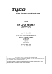
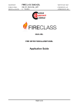
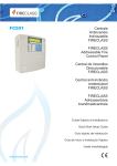
The 3 key shows the panel View log or moves the
panel to the Modify mode;
The 4 key selects between the function groups related
to the keys 1,2,3.
Cursor keys The UP Key: increase the brightness of
LCD display;
the Down Key: decrease the brightness of LCD display;
the Right Key: increase the contrast of LCD display;
the Left Key: decrease the contrast of LCD display;
First Warning
If it blinks
Control panel status indicates the
Control panel
operating normally
Warnings Number
Total :0015
Status: Warning
First
:
MS:Loop 1 det025
Last
:
MS:Loop 1 det030
zone=080
#0011 :
MS:Loop 1 det034
zone=090
Last Warning
Stored Warning
index
zone=078
1° block:
This symbol shows
Point identification
the presence of following
blocks to be scrolled by Right cursor key,
the symbol shows the presence
of previous blocks to be scrolled by
Left cursor key.
Figure 6 DISPLAY: WARNING STATUS
ESC Key Exit from the MAIN page, moves the User Interface to FRONT page or EVENT DRIVEN page.
Pressing the key for more than 3 sec. the panel will be
forced to access Level 1.
ENTER Key No function is related to the ENTER key.
n Diagnostic pages
These pages allow:
Ø To know some electrical parameters inside the panel
(Panel meter page)
Ø To know some functional parameters related to the
loops (LOOP page)
Ø To execute the panel keyboard test (KEYBOARD
TEST page).
These pages are reached during the normal operation
from the Main page after a long pressing of the key 4.
n MENU page
The MENU pages allows the access to the PROGRAM,
ANALYZE, DISABLE and MODIFY features of the
panel. The part relating to the User will be explained in
the sections of this manual: ANALYZE, DISABLE and
MODIFY. The part relative to the Installer will be explained in the section PROGRAM in the Installer manual.
n The EVENT DRIVEN pages
The EVENT DRIVEN pages are pages that are activated
by events in the system and when they becomes active
they override the page present on the display at that time.
Also an EVENT DRIVEN page may be overridden by another EVENT DRIVEN page that has a higher priority.
The following table contains the EVENT DRIVEN page
priority assignment.
The Event Driven pages
Priority
ALARM
0 (highest)
PREALARM
1
FAULT
2
WARNING
3
WALK TEST
4 (Lowest)
In the case of lower priority Event pages (one or more)
being suppressed by the highest priority Event page,
the MORE INFO LED
is ON. In this condition the
suppressed EVENT pages may be manually reached
using the View list. entry in the MAIN page.
n WARNING STATUS
The FC501 fire control panel can be programmed to
provide WARNINGS or PREALARMS status before
ALARM status.
The Warning status will be signalled by the WARNING
display (see Figure 6). The panel will generate a warning when an input point (detector) exceeds its warning
threshold and there is risk of an alarm.
WARNING STATUS will be signalled by:
Ø Warning output points;
Ø fire control panel Display;
Ø intermittent audible signal on the panel buzzer;
Ø the FC500REP repeater.
In this phase:
Alphanumeric keypad 0 key: if the Warning is related
to an item that may be disabled, the User Interface
moves to the disabling page. In order to allow a fast disablement procedure;
1 key: to jump to the Zone status visualization page;
2 key: if the first Warning is related to a point, jump to
LOOP
A
B
C
Panel meter
avg=096
, min=090
avg=170
, min=165
count = 0000
ESC
, max=106
, max=192
ESC
KEYBOARD TEST
ESC
Figure 7 Interaction between the Diagnostic pages
10
Addressable Fire Control Panel
FC501
Total
:0015
First
:
Last
:
#0011 :
status:WARNING
zone: R-D department
zone: Air compressor
zone: Boiler room
Zones:004 / Dev.: 013
EVAC.
n1
zone=456
ALARM+DLY
First Z001
det.: office 3, south wing
Last
det.: main corridor, north
zone=245
Z001
4= view all
Push the right key to scroll
the second block of data
regarding the WARNING zones
status:WARNING
Push the left key
Push the right key to scroll
the second block of data
regarding the Points Coordinate
Total
:0015
First
:
MS:Loop 1 mod012
zone=067
Zones:004 / Dev.: 013
First Z001
Loop 1 mod012
zone=001
Last
:
MS:Loop 1 mod182
zone=456
Last
Loop 1 mod182
zone=001
#0011 :
MS:Loop 2 det034
zone=245
4= view all
Push the right key to scroll
the third block of data
regarding the WARNING causes
Total
:0015
First
:
cause:
Last
:
cause: CP820
Manual
#0011 :
cause: 801PH
Temp.
Z001
ALARM+DLY
Push the right key to scroll
the third block of data
regarding the PREALARM causes
Push the left key
status:WARNING
Zones:004 / Dev.: 013
EVAC.
ALARM+DLY
First Z001
cause: 400PH
Temp.
Last
cause: 400PH
Temp.
Z001
4= view all
Push the right key to scroll
the fourth block of data
regarding the WARNING times
Push the left key
status:WARNING
Push the right key to scroll
the fourth block of data
regarding the PREALARM times
Total
:0015
First
:
Time: 10:46:21
- 01/01/07
First Z001
Zones:004 / Dev.: 013
Time: 10:46:21
- 01/01/07
Last
:
Time: 10:47:18
- 01/01/07
Last
Time: 10:47:18
- 01/01/07
#0011 :
Time: 10:47:12
- 01/01/07
4= view all
Z001
ALARM+DLY
Figure 8 Warning status- Scrolling Right key
Figure 10 Prealarm status- Scrolling Right key
loop device status visualization page;
3 key: if the last Warning is related to a point, jump to
loop device status visualization page;
4 key: to display further Warning.
When a point Warning is present in the fourth row, a further 4 key press will cause the User Interface to jump to
the related loop device status visualization page.
From Figure 6, in the WARNING STATUS, use the
RIGHT Key to scroll the second string of data of Warning Zones; then use the RIGHT Key to scroll the third
string of data of Warning causes; then use the RIGHT
Key to scroll the fourth string of data of Warning Times
and Events.
ends. However, if a second input point (detector in the
same SW zone) detects alarm conditions during the
Prealarm phase (and the “Double knock” option has
been programmed for that zone), the fire control panel
will generate an instant alarm.
If the fire control panel is operating in NIGHT mode, it
will generate INSTANT ALARMS ONLY (Prealarm status will be bypassed automatically). If an alarm procedure is already running, the fire control panel will ignore
prealarm conditions.
+
If the events are linked to the devices, the zone label alternates with the point label every 3 seconds.
If the zone has not been associated with the point,
only the point label will appear.
EN54-2 requires that at the least, the first zone
+ The
in Prealarm, the most recent zone in Prealarm and
the number of zones in Prealarm will be displayed.
Besides to supply the information about the points
in Prealarm, the visualization of the Prealarm (Delay to Alarm) will be by zones (default) or by points.
BY ZONE
Cursor keys Use the UP Key to view the next event,
other than the first and the last;
Use the DOWN Key to view the previous event, other
than the first and the last.
Use the RIGHT Key to view the next string of data.
Use the LEFT Key to view the previous string of data.
First zone in Prealarm
Blinking
Zones in Prealarm counter
zones:004 / Dev:013
n PREALARM STATUS (Delay to Alarm)
This status indicates that an input point (detector) has
exceeded its alarm threshold. The fire control panel will
not generate an alarm until the preset prealarm- time
ALARM+DLY
First z001
zone: RD dept.
Last
z004
zone: Warehouse
4= :
view suppressed Delay to alarm
Last zone in
Prealarm
first floor
To view further zones
in Prealarm
ESC Key Use ESC key to cancel the operation and to
step back to MAIN page.
ENTER Key The ENTER Key blocks/reactivates the
exchange between the labels of the devices and those
of the zones. When the block is enabled, the @ character appears in the top left-hand corner of the display.
Control panel status
Zone label
swapped with
point label
BY POINTS
First Point in
Prealarm
Blinking
Points in Prealarm counter
Control panel status
zones:004 / Dev:013
ALARM+DLY
det: office 3,
Last
z004
det: main corridor
4= :
view suppressed Delay to alarm
To view further points
in Prealarm
This symbol shows
the presence of following
information: point coordinate
Cause
Time
30 sec. or
First z001
Last point in
Prealarm
If blinks
indicates the
control panel
operating normal
first floor
Point label
swapped with
zone label
This symbol shows
the presence of following
information: point coordinate
Cause
Time
Figure 9 DISPLAY: PREALARM STATUS
USER INTERFACE
11
PREALARM status will also be signalled by:
Ø on fire control panel Display;
Ø the LED (1-8) relative the zone in Pre-alarm mode
slow blinking;
Ø an intermittent audible signal on the control panel buzzer;
Ø the prealarm output points.
During the PREALARM phase you will be able to SILENCE, INVESTIGATE or RESET the system and view
the LOG.
The Display in Figure 9shows that the fire control panel
is in PREALARM STATUS: in this phase:
Alphanumeric keypad For the Prealarm by ZONES
or by POINTS the use is the same:
1 key: to jump to the Zone status visualization page;
2 key: to jump to the first activated loop device status visualization page;
3 key: to jump to the last activated loop device status visualization page ;
4 key: to display further Points in Prealarm.
When a point information is present in the fourth row, a
further 4 key press will cause the User Interface jump
the related loop device status visualization page.
Cursor keys For the Prealarm by ZONES or by
POINTS the use is the same:
the UP Key to view the next available point in Prealarm,
other than the first and the last;
the DOWN Key to view the previous available point in
alarm, other than the first and the last.
The RIGHT Key to display the next auxiliary information
about the point (see Figure 10);
The LEFT Key to display the previous auxiliary information about the point.
ESC Key ESC key to step back to the MAIN page.
ENTER Key Long press -> change between the visualization modes;
Short press -> stops or restart the zone/point swap.
BY ZONE
First zone in alarm
Blinking
Zones in alarm counter
Control panel status
zones:004 / Dev:013
ALARM
First z001
zone: RD dept.
Last
z004
zone: Warehouse
4= :
view suppressed Delay to alarm
Last zone in
alarm
To view further zones
in alarm
First Point in
alarm
Blinking
Points in alarm counter
first floor
Zone label
swapped with
point label
BY POINTS
det: office 3,
z004
det: main corridor
4= :
view suppressed Delay to alarm
first floor
Point label
swapped with
zone label
det.: office 3, south wing
Last
det.: main corridor, north
Z001
4= view all
Push the left key
Push the right key to scroll
the second block of data
regarding the Points Coordinate
Zones:004 / Dev.: 013
ALARM
First Z001
Loop 1 mod012
zone=001
Last
Loop 1 mod182
zone=001
Z001
4= view all
Push the right key to scroll
the third block of data
regarding the ALARM causes
Push the left key
Zones:004 / Dev.: 013
ALARM
First Z001
cause: 400PH
Temp.
Last
cause: 400PH
Temp.
Z001
4= view all
Push the left key
Push the right key to scroll
the fourth block of data
regarding the ALARM times
Zones:004 / Dev.: 013
ALARM
First Z001
Time: 10:46:21
- 01/01/07
Last
Time: 10:47:18
- 01/01/07
Z001
4= view all
Figure 11 Alarm status- Scrolling Right key
notes: the point related to the first zone
+ Functional
in Prealarm is the first point in the zone that became active. For all other zones in Prealarm the related point is the last that became active. This
information are update in real time.
The “first point in Prealarm” field contains the information about the first device that became active.
The “last point in Prealarm” field contains the information about the last activated point, no matter on
which zone belong.
n ALARM STATUS
In the ALARM status, an alarm has been raised by a detector or manual call point.
ALARM status will also be signalled by:
Ø blinking ALARM LEDs;
Ø message on fire control panel/Repeater Display (see
Figure 12);
Ø an intermittent audible signal on the fire control panel;
Ø the Alarm output points, programmed to signal the
Alarm status. In this phase:
number of zones in alarm will be displayed.
Besides to supply the information about the points
in alarm, the visualization of the alarm will be by
zones (default) or by points.
Alphanumeric keypad For the alarm by ZONES or by
POINTS the use is the same:
1 key: to jump to the Zone status visualization page;
ALARM
Last
To view further zones
in alarm
This symbol shows
the presence of following
information: point coordinate
Cause
Time
Control panel status
First z001
ALARM
First Z001
EN54-2 requires that at the least, the first zone
+ The
in alarm, the most recent zone in alarm and the
30 sec. or
zones:004 / Dev:013
Last point in
alarm
If blinks
indicates the
control panel
operating normal
Zones:004 / Dev.: 013
This symbol shows
the presence of following
information: point coordinate
Cause
Time
the FC500REP repeater case in addition to
+ Inpress
F1 key , you have to press ENTER key to visualize the zone label.
Figure 12 DISPLAY: ALARM STATUS.
12
Addressable Fire Control Panel
FC501
2 key: to jump to the first activated loop device status visualization page;
3 key: to jump to the last activated loop device status visualization page ;
4 key: to display further Points in alarm.
When in the fourth row is present a point information, a
further 4 key press will cause the User Interface jump
the related loop device status visualization page.
Cursor keys For the alarm by ZONES or by POINTS
the use is the same:
Use the UP Key to view the next point in alarm, other
than the first and the last;
Use the DOWN Key to view the previous point in alarm ,
other than the first and the last.
Use the RIGHT Key to display the next auxiliary information about the point .
Use the LEFT Key to display the previous auxiliary information about the point.
ESC Key Use ESC key to step back to the MAIN page.
ENTER Key Long press -> change between the visualization modes;
Short press -> stops or restart the zone/point swap.
notes: the point related to the first zone
+ Functional
in alarm is the first point in the zone that became
active. For all other zones in alarm the related point
is the last that became active. This information are
update in real time.
The “first point in alarm” field contains the information about the first device that became active.
The “last point in alarm” field contains the information about the last activated point, no matter on
which zone belong.
+
For the WALK TEST status, displays and procedures are similar to the FAULT status
n FAULT STATUS
FAULT status will also be signalled by:
Ø blinking FAULT LEDs;
Ø message on fire control panel Display;
Ø blinking the specific FAULT LEDs, if present
(POWER SUPPLY FAULT - BATTERY TROUBLEEARTH FAULT-SYSTEM FAULT-FIRE SIGNAL
FAULT- SOUNDERS FAULT/DIS);
Ø an intermittent audible signal on the fire control panel;
Ø the Fault output points.
First Faults
Total
:0004
First
:
Last
:
#0002 :
Last Faults
If it blinks
Control panel status the panel is
operating normally
Faults number
status: FAULT
MS:
SHORT on Sc1
MS:L1
Signal Path broken
MS:Loop 2
Stored Faults
index
det191
zone=002
1° block:
This symbol shows
Point identification
the presence of following
blocks to be scrolled by Right cursor key,
the symbol shows the presence
of previous blocks to be scrolled by
Left cursor key.
Figure 13 DISPLAY: FAULT STATUS.
Total
:0004
First
:
Last
:
#0002 :
status:FAULT
MS:
SHORT on SC1
MS:L1
Signal Path broken
zone: Reception
Push the right key to scroll
the second block of data
regarding the FAULT zones
Total
:0004
First
:
Last
:
#0002 :
status: FAULT
zone:
System Area
zone:
System Area
MS:Loop 2 det191
zone=002
Push the right key to scroll
the third block of data
regarding the FAULT causes
Total
:0004
status: FAULT
First
:
NO DATA
Last
:
#0002 :
cause:
cause:
NO DATA
cause: 801PH
NOT RESPONDING
Push the right key to scroll
the fourth block of data
regarding the FAULT times
Total
:0004
First
:
Time: 08:34:46
status: FAULT
Last
:
Time: 08:36:23
- 01/01/07
#0002 :
Time: 08:36:13
- 01/01/07
- 01/01/07
Figure 14 Fault status- Scrolling Right key
Figure 13shows the Fault status of the control panel.
The SILENCE button can be used to force the FAULT
Silenceable output momentarily to standby status.
FAULT MEMORY will be signalled by blinking on the
FAULT LEDs ONLY.
The RESET key can be used to force ALL Fault outputs to
standby and clear the fault memory. The fault outputs will
restore automatically to standby when faults clear.
In this phase:
Alphanumeric keypad Use the 1 key to jump to the
Zone status visualization page.
Use the 2 key if the first fault is related to a point, jump to
loop device status visualization page.
If the first fault is a loop break fault, jump to the “locate
the loop break” page.
If the first fault is related to an item that may be disabled,
the User Interface moves to the disabling page; in order
to allow a fast disablement procedure.
access level is less than L2, the password will
+ Ifbetherequired
before proceed to disablement
Use the 3 key if the last fault is related to a point, jump to
loop device status visualization page.
If the last fault is a loop break fault, jump to the “locate
the loop break” page.
If the last fault is related to an item that may be disabled,
the User Interface moves to the disabling page; in order
to allow a fast disablement procedure.
access level is less than L2, the password will
+ Ifbetherequired
before proceed to disablement
Use the 4 key to display further faults.
When a point fault is present in the fourth row, a further
4 key press will cause the User Interface jump to the related loop device status visualization page.
When a point fault is present in the fourth row, a further
USER INTERFACE
13
4 key press will cause the User Interface jump to the “locate the loop break” page. If in the fourth row is present
a fault related to an item that may be disabled, the User
Interface moves to the disabling page in order to allow a
fast disablement procedure.
Loop ID
Locate the loop break on: Loop 1
ESC to EXIT
access level is less than L2, the password will
+ Ifbetherequired
before proceed to disablement
Go back to
Fault page
Locate the loop break on: Loop 1
From Figure 14, in the FAULT STATUS, use the RIGHT
Key to scroll the second string of data of fault Zones;
after use the RIGHT Key to scroll the third string of data
of Fault causes;
then use the RIGHT Key to scroll the fourth string of
data of Fault Times and Events.
+
In the case of a fault is related to a Loop device, the
faulty point label is swapped with the assigned
zone label every 3 seconds. If the zone has not
been associated with the point, only the point label
will appear.
Cursor keys Use the UP Key to view the next available fault, other than the first and the last.
Use the DOWN Key to view the previous available fault,
other than the first and the last.
Use the RIGHT Key to view the next auxiliary information about the point.
Use the LEFT Key to view the previous auxiliary information about the point .
ESC Key Use the ESC key to step back to MAIN page.
ENTER Key The ENTER Key blocks/reactivates the
exchange between the labels of the devices and those
of the zones.
n Locate loop break pages
From paragraph Fault status -2 Key.
These pages are used to manage the “locate loop
break” procedure that helps to understand where the
loop is broken giving as result the number of sensed detector on the left and on the right side of the analyzed
loop.
The pages sequence is depicted in figure n.15.
+
Note that during the “locate loop break” procedure
all the detectors will be powered down, so at the
exit of the procedure a full loop initialization will be
executed.
the “locate loop break” procedure" the de+ During
vices not in configuration are not found.
IN PROGRESS
Locate the loop break on: Loop 1
XXX devices on left side
XXX devices on right side
ESC to Exit
The sounders will start to sound, while the beacons will
start to flash.
The following picture diplay the “locate not addressed
device page” diagram flow.
If there are too many not addressed devices, the overall
current required to keep active, at the same time, all the
LEDs, sounders and beacons, may be so high to trigger
the loop overcurrent protection circuit.
For this reason the operator is warned about this possibility.
feature is made available only when the panel
+ This
reach its stand-by status (scanning loop).
Total:0001
First : MS:
Last :
2
3
GHI
4
JKL
Make visible not addressed devices
WARNING!
If too many dev. the loops may shutdown
ESC=Exit
ENTER=Execute
The not addressed
devices
are made visible
To MAIN
page
FAILED
Make visible not addressed devices
Devices Visible
ESC=Exit
SILENCE=Stop
To MAIN
page
The not addressed
devices are silenced
The not
addressed
devices
are made
visible
Make visible not addressed devices
Devices is silenced
ESC=Exit
14
Status: FAULT
NOT PROGRAMMED DEV.
DEF
n Locate the not addressed devices
In the case of “NOT POGRAMMED DEV.” fault it is possible to locate all the not addressed devices.
To make visible all the not addressed devices that have
a LED, they will be activated (steady on).
ENTER to Restart
Figure 15 Page "Locate loop break"
the immediate future, in case of short circuit on a
+ Inloop,
the control panel will indicate a fault for short
circuit on the other loops. Only later, with “locate
loop break” procedure it is possible to see which of
the three Loop occurred on short circuit.
ENTER to EXECUTE
SILENCE=Excute
To MAIN
page
Figure 16 Locate the not addressed devices pages
Addressable Fire Control Panel
FC501
VIEW-LOG-PARAMETERS
Read through the following section carefully, in order to
get an overall view of how to use the Programming for
the Users. For details regarding the parameters of each
phase, refer to the respective paragraph in the “PROGRAMMING FROM A PC” chapter of the Installation
Manual.
From Main Page, the User can manage without Access
code:
Ø View parameters (Use 1=ANALYZE)
Ø View Log (Use 3= View LOG or 1=ANALYZE and
then use 8 Key)
Ø View Lists (Use 4= MORE and then 2)
and with User Access code can manage this menu:
Ø Modify
Ø Disable
7 = Option: activates the viewing sequence for all locally programmed system options;
8= Log: start the procedure for viewing of Logged
events;
9= Fw ver.: start the procedure for viewing of FW version of all processors in the panel;
0= Panel: start the procedure for viewing Panel
informations.
Cursor keys No function is related to the UP,Down,
Right and Left key.
ESC Key Use the ESC key to step back to MAIN page.
ENTER Key No function is related to the ENTER key.
n View parameters
The Display (Figure 17) shows how to manage the
viewing of different parameters:
In this phase:
Alphanumeric keypad Use the Alphanumeric keypad
to select the different viewing functions:
1= Loop: start the procedure for selection and viewing
of the loop data;
2= To activate the selection and visualization sequence
of the loop devices real time data;
3 = SW zone: activates the selection and display procedure for the data corresponding to all SW zones;
4 = Output: activates the selection and viewing procedure for the data corresponding to an output;
5= Network: start the procedure for viewing of all devices (Repeaters and MFI module) on the RS485 Network;
6 = Communic: activates the viewing sequence for all
communication units main data;
If it blinks the panel
Control panel status is operating normally
Control panel name
Access Level
FC501 panel
lev.1:
ANALYZE
1=Loop
2=Device
3=SW zone
4=Output
5=Network
6=Communic.
7=Option
8=Log
9=FW ver.
0=Panel
Options
Figure 17 Display: View Parameters.
VIEW-LOG-PARAMETERS
15
1 KEY - View Loop
2 KEY - View Devices
Use the 1 Key to view the Loop data (see Figure 18).
Use the 2 Key to view the Loop devices (see Figure 19).
In this page: Select the Loop and then the device.
n View of Loop Details
In this phase:
n Select the Loop
In this phase:
Alphanumeric keypad No function is related to Alphanumeric keypad.
Cursor Keys Use the UP Key to select the next Loop
data;
Use the Down Key to select the previous Loop data;
No function is related to the Right Key;
No function is related to the Left Key.
ESC Key Use ESC key to step back to previous page.
ENTER Key No function is related to the ENTER key.
In the Figure n. 18, the “loop=” field shows which loop
detail is displayed.
The “Detectors:” field displays the number of detectors
sensed on the relevant loop.
Alphanumeric keypad 1,2,3 used to select the loop.
Cursor Keys No function is related to UP Key;
No function is related to the Down Key;
Use the Right Key to select the next available Loop;
Use the Left Key to select the previous available Loop.
ESC Key Use the ESC key to cancel the operation and
to step back to previous page.
ENTER key Use the ENTER key to confirm and to display the page of the selected Loop.
n Select the device
After selecting the Loop, the Loop details are shown as
in Figure 20;
in this phase:
The “Modules:” field displays the number of modules
sensed on the relevant loop.
The “Status:” field displays the status of the selected
loop. The possible values are:
Ø Working,
Ø Fault,
Ø Stand_by,
Ø Disabled.
The “loop=” field real time display (5s data refresh rate)
the total current supplied to all three loops.
Alphanumeric keypad Use the Alphanumeric keypad
to insert the device address. If the address does not exist the next available device will be selected.
is in the system, the square brackets
+ Ifwillthebedevice
shown near the address. If the address does
not exist or it is different from that selected in the
underlying bar, the arrows will be shown.
Cursor Keys No function is related to the UP Key;
No function is related to the Down Key;
Use the Right Key to select the next available Device;
Use the Left Key to select the previous available device.
ESC Key Use the ESC key to cancel the operation and
to step back to previous page.
ENTER key Use the ENTER key to confirm and to display the page of the selected device.
If it blinks the panel
is operating normally
Detectors Number
Loop number
Loop= 01
Modules
Present Status
of the Loop
Choose Panel
[ L1 ]
Loop 1
L2
(400 ma MAX)
Current Value
in the 3 Loops
Overcurrent that
powers OFF the Loop
Figure 18 DISPLAY: Viewing Loop details
16
lev.1: ANALYZE
Master Panel
: 125
Status: Working
ILoop=073 mA
Control panel status If it blinks the panel
is operating normally
Access level
FC501 Panel
lev.1: ANALYZE
Detectors: 125
Control panel name
Modules
number
Initial of the selected
Control panel
Name of the selected
Control panel
Figure 19 Display: viewing a) Loop choice, b) Loop details
Addressable Fire Control Panel
FC501
n View device data on the Loop
Selected the Loop and then the device, the Display will
show Figure 20.
In this phase:
Alphanumeric keypad No function is related to the Alphanumeric keypad except 0 key to disable the device
(detector or module), it will required the entry of the access code if the access level is less than 2.
+
NOTE: This feature doesn’t work in the case of
multichannel module not answering to loop poll.
Cursor Keys The UP Key, in the case of modules with
several inputs or outputs, can scroll through them;
The Down Key in the case of modules with several inputs or outputs, can scroll through them;
the Right Key: displays the status of the next device on
the same loop; the Left Key: displays the status of the
previous device on the same loop; in the case of modules with several inputs or outputs, this means it is possible to scroll through them.
Control panel status if it blinks the panel
is operating normally
Access level
Control panel name
FC501 panel
lev.1 : ANALYZE
Master Control panel
Choose Loop
[ L1 ]
Initial of the selected
Loop
Loop 1
L2
List of the
present Loop
This symbol shows the
device
Control panel name
presence
Label of
Control panel
Name of the
selected Loop
Control panel status
Access level
FC501 panel
lev.1: ANALYZE
Add= > 123 <
Master control Panel
Name of the
Control panel
Loop 1
D001 [d187] m250
Inserted
address
Selected
device
801PH
List of the
present
devices
Selected device
type
Name of the
selected Loop
IN THE DETECTOR CASE
Device status
Address
“
”
Device name
Type
Office Zone
stat: WORKING
Add:163 Type:801PH
s=07%
Zone: 32
T=26%
Assigned
zone
Sizes value
tested by detector
The device
coordinate field
----|--t=60%
---|-A2S
Threshold
Function
mode
Pattern of the
current value and
Threshold (if applicable)
IN THE MODULE CASE
Device status
Device name
ESC Key Use the ESC key to cancel the operation and
to step back to previous page.
Type
Reception
stat: WORKING
L1:038 800MIO inp1
MAIN door
Zone: 32
-|--|-C:NO
WORKING
ENTER key No function is related to the ENTER key.
Assigned
zone
The Device status field displays the current status of the
detector or module, the possible values are:
30%
Pattern of the
current value and
Threshold (if applicable)
Figure 20 Following displays of View devices on the
Loop (Detectors and Modules)
-WORKING
-ACTIVE
-WARNING
-FAULT
-ZONE DIS.
-WALK TEST
-STAND-BY.
The device coordinate field displays:
-the loop ID,
-the device address,
-the device type,
-the channel ID (for the modules).
The “Device channels info area” displays:
-the channel ID S=Smoke, T=temperature, C=Carbon
monoxide (for the detector),
-the current analog value in percentage,
-a real time, pseudo-graphic representation of the current analog value with threshold,
-the channel configuration mode or the threshold value
-the channel status.
device info is displayed only in the case of de+ The
vices in WORKING state.
VIEW-LOG-PARAMETERS
17
3 KEY- View SW Zone
4 KEY- View Output
The 3 Key (SW Zone) option in the ANALYZE menu activates the viewing of the software zones (max 32). During this phase (see Figure 21) the status of all the SW
zones in the system is displayed in compact format. The
status of the SW zones will be displayed using the following abbreviations:
. : “UNUSED” Not used zone, no devices assigned to it
A: “ALARM” zone in Alarm mode
P: “PRE AL.” zone in Pre-alarm mode
W: “WARNING” zone in Warning mode
F: “FAULT” zone in Fault mode
X: “DISABLED” zone Disabled
t: “TEST”
zone in Test mode
T: “TEST ON” At least one point in the zone is active in
test
_: “ST-BY” zone in standby mode
D: “DIRTY” At least one smoke detector in the zone is
dirty.
The 4 key Output option in the ANALYZE menu activates the viewing of the Outputs. During this phase (see
Figure 22) the status of all the Outputs in the system is
displayed in compact format. The status of the Outputs
will be displayed using the following abbreviations:
-DIS: output disabled
-ACT: output active
-SC: output shorted
-OPE: output open
-_ _ : output in standby
-FAU: transistor Fault
Alphanumeric keypad No function is related to Alphanumeric keypad.
Cursor Keys No function is related to the UP, Down,
Right and Left key.
ESC Key Use the ESC key to cancel the operation and
to step back to previous page.
ENTER key No function is related to the ENTER key.
Cursor Keys No function is related to UP key.
No function is related to the Down key;
the Right Key: selects the next SW zone, in the “All
zone status area”;
(the corresponding number appears on the Left of the
display);
the Left Key: selects the previous SW zone, in the “All
zone status area”;
(the corresponding number appears on the Left of the
display).
ESC Key Use ESC key to cancel the operation and to
step back to previous page.
ENTER key No function is related to ENTER key.
Zone Number ID
SC1 Output
All zones status area
OUTPUT STATUS
Zone
011
A - - - - F-[
First Floor
OC:
ST-BY
SW zone status
Zone Label
Figure 21 Display view SW zone
18
]
01
SC1: --
Open
Collector Output
02
--
OPE
--
ST-BY status
Figure 22 Display view Outputs
Addressable Fire Control Panel
FC501
5 KEY- View NETWORK
6 KEY- COMMUNICATORS
Use the 5 Key to view the Network devices: MFI modules (max 4) and Repeaters (max4) (see Figure 23).
The 6 Key is used to view the Communicator connected
to the control panel, see Figure 24. In addition to the
Firmware version, the FC500IP module status and the
address will be displayed.
The field Network devices status displays the related
output status using abbreviations.
In this phase:
The abbreviations are:
“ OK!”, the net. device is sensed as connected and
working
“ Ko!”, the net. device is sensed as not connected
“ FAU”, the net. device is faulty
“ DIS”, the net. device is disabled
“ — ”, the net. device is not configured in the network
“ OLD”, the net. device has an obsolete FW version.
Alphanumeric keypad No function is related to Alphanumeric keypad.
Cursor Keys No function is related to the UP, Down,
Right, Left Key.
ESC Key Use the ESC key to cancel the operation and
to step back to previous page.
ENTER key No function is related to the ENTER key.
In this phase:
Alphanumeric keypad No function is related to Alphanumeric keypad.
Cursor Keys No function is related to the UP, Down,
Right, Left Key.
ESC Key Use the ESC key to cancel the operation and
to step back to previous page.
ENTER key No function is related to the ENTER key.
Communicators status
MFI
M1
M2
M3
M4
-R3
--
FAU
R4
Ko!
IP:
REPEATER
OK! -R1 R2
-- --
Network devices status
Type of Communic.
Network type
devices
FW ver.
Figure 23 Example of Display: View Network (MFI modules and Repeaters)
OK!
01.00.09
Firmware Rev.
Address
255.255.255.255
IP Address of the
FC500IP module
Figure 24 Display Communicators
VIEW-LOG-PARAMETERS
19
7 KEY- View Option
View Log
The 7 Key activates, in the ANALYZE MENU, the viewing of programmed system options, see Figure 25. The
status of the DAY/NIGHT MODE options will be indicated using the following abbreviations:
-DAY: day mode
-NGT: night mode
-AUT: automatic mode.
From MAIN page directly, (see Figure 5) the User, without password, can arrive to View Log see Figure 26.
In this phase:
Alphanumeric keypad No function is related to Alphanumeric keypad.
Cursor Keys No function is related to the Up, Down,
Right and Left Key;
ESC Key Use the ESC key to cancel the operation and
to step back to previous page.
ENTER key No function is related to the ENTER key.
8 KEY - View Log
Use the 8 Key to select View LOG (see Figure 26) or directly from the STANDBY status.
The option View Log of the menu View parameters
will allow you to view the stored events in the Log of the
fire control panel.
This Control panel can store the last 4000 occurred
events.
When the Log is full, the oldest event will be deleted, so
the newest can be stored.
the option CLEAR LOG of the Modify menu to
+ Use
delete the Log events.
The following data will be stored in the LOG:
Ø Event description;
Ø Event number;
Ø Description of the device (Panel or Repeater) that
generated the event;
Ø Description of the item that generated the event;
Ø Time and date of the event;
Ø Address of the Item which generated the event.
The Event Class field displays the class of the event
currently displayed, the possible values are:
RESTORE
ALARM
ALARM+DLY
WARNING
FAULT
GENERIC
WALK TEST.
In this phase:
Alphanumeric keypad Used to activate the display filters.
1: Alarm events only, 2: Pre-alarm events only, 3:
Warning events only, 4: Walk Test events only, 5: Fault
events only, 6: Restore events only, 7: Generic events
only.
Cursor Keys Use the UP Key to select the previous
available event;
Use the Down Key to select the next available event;
Use the Right Key to view the next available data;
Use the Left Key to view the previous available data.
ESC Key Use ESC key to cancel the operation and to
step back to main page.
ENTER key No function is related to the ENTER key.
events are linked to the devices, the zone la+ Ifbelthealternates
with the point label every 3 seconds.
If the zone has not been associated with the point,
only the point label will appear.
If the displayed events are filtered by type, “*” will
+ immediately
begin to blink to the right of the event
number.
If it blinks the panel
Control panel status is operating normally
Total stored Events
Control panel status If it blinks the panel
is operating normally
Access Level
Options
DAY
^
Total
:0297
Event
:0292 *
Lev.1: ANALYZE
DAY NIGHT MODE
ngt aut
Master panel
Current state
DAY
If present, it shows the filtered
view by type of events
20
Display: View Option.
RESTORE
MS:Loop 2
det191
zone=002
Events
Type
1° block
08:43:11 - 01/01/07
At present
stored events
Mode Type
Figure 25
status: VIEW LOG
Time and date
conncted to
the event
This symbol:
shows the presence of
following blocks to be scrolled by RIGHT key
( previous block to be scrolled by LEFT key)
Figure 26 Display: View LOG.
Addressable Fire Control Panel
FC501
0 Key-Panel
Total
:0297
Event
:0292
status: VIEW LOG
RESTORE
MS:Loop 2
det191
zone=002
08:43:11 - 01/01/07
Push the right key to scroll
the second block of data
regarding the zones in the LOG
Total
:0297
Event
:0292
status: VIEW LOG
RESTORE
Zone: Reception
08:43:11 - 01/01/07
Push the right key to scroll
the third block of data
regarding the causes in the LOG
Total
:0297
Event
:0292
status: VIEW LOG
By pressing the 0 key, in the ANALYZE menu, it is possible to read:
- the fire panel ID
- the serial number of the Fire Panel (displays the electronic board serial number composed by eight
hexadecimal digits);
- the version of the PCB;
- the type of power supply on board;
- the type of batteries on board
- the presence of the auxiliary controller (see Figure 29).
In this phase:
Alphanumeric keypad No function is related to Alphanumeric keypad.
RESTORE
Cause:8011H
NO DATA
Cursor Keys No function is related to the Up, Down,
Right and Left Key;
08:43:11 - 01/01/07
Figure 27 View LOG: scroll with RIGHT key
ESC Key Use the ESC key to step back to ANALYZE
menu page.
ENTER key No function is related to the ENTER key.
9 Key - View FW version
The option Ver. FW of the View Parameters Menu allows you to view the Firmware version of Fire control
panel.
Use the 9 key to view the Firmware version of Fire control panel (see Figure 28), in this phase:
Alphanumeric keypad No function is related to Alphanumeric keypad.
Cursor Keys No function is related to the Up, Down,
Right and Left Key.
ESC Key Use the ESC key to cancel the operation and
to step back to MAIN page.
ENTER key No function is related to the ENTER key.
If it blinks the panel
is operating normally
PANEL INFO
FIRMWARE VERSIONS
MAIN CONTROLLER
ver 01.00
sv01
AUX. CONTROLLER
ver 01.00
sv03
Figure 28 Display: Viewing FW version.
ID=0001
Ser.Num.
123456789
PCB ver.0
PSU
27.6V.
Batteries
Aux.Contr.
PRESENT
1.5Ah
7Ah
ESC to exit
Figure 29 Display: Viewing Panel info.
VIEW-LOG-PARAMETERS
21
View Lists (Press 4= MORE and then 2)
In this phase (second Display in Figure 30):
Directly from the MAIN page, press 4 =MORE Key and
then 2= View Lists.
Alphanumeric keypad To call the enablement page
to quickly enable the displayed entity.
The option View Lists allows you to view:
Ø 1- Dis. Zone-Disabled zones
Ø 2-Dis. Device-Disabled devices
Ø 3-Dis. Part-Disabled Parts
Ø 4-Walk test - Walk test Zones
Ø 5-Faults List
Ø 6-Warnings List
Ø 7-Dev. in test (Devices in test).
Cursor Keys The UP Key, used to navigate the list,
displays the next element;
The Down Key, used to navigate the list, displays the
previous element;
No function is related to the Right key;
No function is related to the Left key.
lists containing data (not empty) are indicated
+ The
by the blinking of the corresponding number
ESC Key Use the ESC key to cancel the operation and
to step back to previous page.
ENTER key No function is related to the ENTER key.
In this phase:
Alphanumeric keypad Alphanumeric keypad is used
to select and access the View function (see options
above).
Cursor Keys No function is related to the Up, Down,
Right and Left key.
ESC Key Use the ESC key to cancel the operation and
to step back to previous page.
ENTER key No function is related to the ENTER key.
The field “Item in the list” contains the number of items
present in the list at the moment of it opening;
the field “Current item ID” contains the number ID of the
currently displayed item;
The field “Kind of list” replicates the name of the list previously selected.
The field “Item info” displays the information about the
item currently selected. It shows the location of the SW
zone and loop device or the description of a system part
plus the related label.
Control panel status If it blinks the panel
Acces level
is operating normally
Control panel name
FC501 Panel
lev.1 : ANALYZE
1=Dis.Zone
2=Dis. Dev.
3=Dis.Part
4=Walk Test
5=Faults
6=Warnings
7=Dev.in Test
Choice Options
For the Dis.Zone, Dis. Dev, Dis. Part and Walk Test a common visualization list page is used
Current Item ID
Items in the list
Total
:
0003
VIEW LIST
Index
:
0002
DIS: Zones
SW Zone 007
Kind
of list
Info
First Floor
Figure 30 Display: View Lists
22
Addressable Fire Control Panel
FC501
MODIFY
MODIFY MENU
1 KEY -INIT MSG (Modify panel label)
For the MODIFY option, from the MAIN page, press the
3 key.
Use the 1 Key to enter or update the Panel label.
In this phase:
To access the MODIFY Menu:
Enter the User Access code (11111 at default), each
digit will be masked by * (asterisk).
Alphanumeric keypad The Alphanumeric keypad is
used to enter or update the panel label.
The following options are available in this menu:
1-Clear and update the Welcome message (Init MSG)
(control panel name),
2- Enter and update L2- User Password,
3- Update Day/Night mode
4- Update Time and Date
5- Clear LOG
6-Zone Walk test.
Figure 31shows the options for the MODIFY MENU after inserting or modifying the password.
Cursor Keys Use the UP key to change the selected
letter from lower case to upper case;
Use the Down Key to change the selected letter from
upper case to lower case;
Use the Right Key to select the next character to be
modified;
Use the Left Key to select the previous character to be
modified.
ESC Key Use the ESC key to cancel the operation and
to step back to previous page.
ENTER key Use the ENTER key to confirm the label.
In this phase:
Alphanumeric keypad Use the Alphanumeric keypad
to select the options of MODIFY MENU.
Cursor Keys No function is related to the UP, Down,
Right and left Key.
ESC Key Use the ESC key to cancel the operation and
to step back to previous page.
ENTER key No function is related to the ENTER key.
Name of Control Panel
FC501 panel
Access level
Control panel If it blinks the panel
is operating normally
Status
lev.2 : MODIFY
1=Init MSG
2=l2-User PassWord
3=Day/Night
4=Time and Date
5=Clear LOG
6=Zone Walk Test
Options
Figure 31 Display MODIFY MENU.
MODIFY
23
2 KEY - User Password
3 KEY-DAY/NIGHT
Use the 2 key to Modify the User Password (see Figure
32).
If the 3 Key is pressed, it is possible to change the control panel operating mode: Day mode or Night mode.
n Insert or Modify Password
Select the option MODIFY, the display will show Figure
32; in this phase:
The Day/Night mode will be toggled at each key 3
press.
Alphanumeric keypad Use the Alphanumeric keypad
to enter the last 5 digit User password.
+
To avoid the use of the same password for multiple
users, as the first digit of password, the User must
enter the number corresponding to his position,
see the following.
The first digit for the User 1: is 1
The first digit for the User 2: is 2
The first digit for the User 3: is 3
The first digit for the User 4: is 4
The first digit for the User 5: is 5
The first digit for the User 6: is 6
The first digit for the User 7: is 7
The first digit for the User 8: is 8.
Day mode indicator light
+ The
tus.
will change sta-
n Day/Night Mode
The control panel can operate in DAY or NIGHT Mode.
If the system is silenced during DAY Mode, SILENCE
status will be held until the system is unsilenced (i.e. until new alarms or faults occur). If the system is silenced
during NIGHT Mode, SILENCE status will be held until
the Night Mode Silence time expires. On power up (at
default) the system will set to DAY Mode. During this
operating mode, silenced alarms/faults will not be
unsilenced automatically.
control panel will generate an Instant Alarm if
+ This
alarm conditions are detected during Night Mode
or if an alarm is triggered from a Callpoint.
Cursor Keys No function is related to the UP, Down,
Right and Left Key;
ESC Key Short press: Abort the enter password procedure and exit;
Long press: clear all the entered digits.
ENTER key Use the ENTER key to confirm the password and start the password verification process.
or empty password is entered the sec+ Ifonda wrong
page in Figure 32, will be displayed for 5s.
Name of Control Panel
Access Level
FC501 Panel
USER#1
If it blinks the panel
Control panel is operating normally
Status
lev.2: MODIFY
Enter the new password
Enter 1 as first digit
If it blinks the panel
is operating normally
[_____]
Access level
Control panel
Status
Field to enter the password
a)
System
PANEL NAME
FC501 Panel
[--------------------]
^
lev.2: MODIFY
USER
WRONG Password
Cursor (20 characters max)
Figure 32 Display: Modify User password
24
lev. 2 : MODIFY
FC501 Panel
Name of Control Panel
Figure 33 Display Panel label
Addressable Fire Control Panel
FC501
4 Key-Time and Date
5 Key- Clear LOG
Use the 4 Key to select TIME and DATE in the MODIFY
menu to enter/change the control panel Time and Date
(see Figure 34).
Use the 5 key to select Clear LOG (see Figure 35).
In this phase:
Alphanumeric keypad The alphanumeric keypad is
used to enter the Time and Date values.
This option allows you to delete all stored events in the
fire control panel.
Key is selected, confirmation of this deletion
+ Ifwillthebe5 requested,
as all data will be lost.
In this phase:
Cursor Keys No function is related to the UP Key;
No function is related to the Down Key;
Use the Right Key to select the next value to be inserted/modified;
Use the Left Key to select the previous value to be inserted/modified;
Alphanumeric keypad No function is related to the alphanumeric keypad.
Cursor Keys No function is related to the UP, Down,
Right and Left Key.
ESC Key Use the ESC key to cancel the operation and
to step back to previous page.
ESC Key Use the ESC key to cancel the operation and
to step back to previous page.
ENTER key Use the ENTER key to confirm the Time
and the Date.
ENTER key Use the ENTER key to confirm the procedure to clear Log..
incorrect values a message will show
+ Iftheyouerrorenter
as shown in Figure 34a.
the Clear LOG activity the MAIN page will
+ During
be displayed with the Panel activity field loaded
with CLEAR LOG string (see Figure 35). Once the
Log has been cleared, the panel resets.
Control panel status
Access level
System
DATE and TIME
hh.mm.ss
^
WARNING!
All logged data will be lost.
Lev 2: MODIFY
FC501 CONTROL PANEL
ESC=NO
mm.dd.yy
Enter Date and Time
Do you want to continue?
ENTER=Yes
Control panel Status
Access Level
a)
Lev 2: ACTIVE
FC501 CONTROL PANEL
CLEAR LOG
WRONG VALUE!
Please enter the parameter again
17.00.24 - 04/02/13
Control panel name
Figure 34 Display Time and Date
Figure 35 Display "Clear LOG"
MODIFY
25
6 KEY- Zone WALK TEST
The Zone Walk Test option of the MODIFY menu will
activate the zone programming procedure for the Zone
walk test (see Figure 36) .
n SW zone in WALK TEST
After selecting the SW Zone, you will be able to enable or
disable the option Zone in WALK TEST (OFF) or not (off);
Ø if the option all (ALL) is selected, all the devices assigned to zones in WALK TEST mode, will NOT generate alarm in the case of their activation but they will
reach the TEST status.
Ø If the option det (DET) is selected, only the detectors
assigned to zones in WALK TEST mode, will NOT
generate alarm in the case of their activation but will
reach the TEST status.
Ø If the option cp (CP) is selected, only the call-points
assigned to zones in WALK TEST mode, will NOT
generate alarm in the case of their activation but will
reach the TEST status.
The presence of a zone in WALK TEST mode is signalled by the
TEST yellow LED on the User Interface. More than one zone can be put in WALK
TEST mode at the same time.
English User Interface version, the Icons are
+ Innotthepresents.
Alphanumeric keypad Use to enter the SW zone
number.
Cursor Key No function is related to the UP and Down
Keys;
The Right key: selects the next: OFF-ALL-det-cp;
The Left key: selects the previous: OFF-ALL-det-cp.
ESC Key The ESC key cancels the procedure and returns to the programming page.
ENTER key The ENTER key accepts the selection
and activates the corresponding programming page.
a)
Panel status
SW Zone Index
Access Level
FC501 Panel
lev.2:
Zona SW: 002
FC501 Panel
Enter the
SW zone
b)
SW Zone
ZONE IN WALK TEST
If it blinks the panel
is operating normally
MODIFY
Name of
the selected
panel
number
Panel status
Access Level
lev.2:
MODIFY
Name of
the selected
panel
FC501 Panel
OFF All det cp
Choose the option
Figure 36 Display WALK TEST option
26
Addressable Fire Control Panel
FC501
DISABLE
To access the DISABLE menu from the MAIN page,
you will be asked to enter a “User PIN” password (the
default PIN is 11111): each entered digit will be hidden
with the * symbol.
The Display (see Figure 37) shows how to select the
devices to Disable/Enable.
This activates the procedure used to enable/disable:
Display List of disabled devices, the loop devices (input
or output devices), the SW zones, the Outputs of the
control panel, the network devices, the Telecom modules, the User password and the RELÈ FIRE Output;
Input Devices A disabled input device (Detector, Input module, Conventional Zone module, Addressable
Call-points) will not generate ALARM or FAULT status.
Alphanumeric keypad Use the Alphanumeric keypad
to select the Disable/Enable options.
Use the 1 key to select the Disab. List.
Use the 2 key to select the Disable option of Loop devices.
Use the 3 key to select the Disable option of SW zones.
Use the 4 key to select the Disable option of Outputs.
Use the 5 key to select the Disable option of Device in
the Network.
Use the 6 key to select the Disable option of Comunic.
devices.
Use the 7 key to select the Disable option of the User
Password # 2.... # 8 and Installer # 2.
Use the 8 key to select the Disable option of the FIRE
relay output.
Ø To clear ALARM status generated by an input device
- RESET the fire control panel.
option 7 can be enabled only by the Installer
+ The
#1 password (default 00000)
Output Devices ALARM or FAULT status will not activate disabled output devices (Output modules, Addressable Sirens).
Cursor Keys No function is related to the UP, Down,
Right and Left Keys.
at least a device is disabled, the Disable
+ When
LED will be glowing
, and any Alarm or Fault,
related to the disabled device, will be ignored.
The disabled and enabled modes are as follows:
Ø To stop the output devices activated by FAULT status - Disable the devices concerned.
Ø To stop the output devices activated by an ALARM
status - RESET the fire control panel.
In this phase:
ESC Key Use the ESC key to cancel the operation and
to step back to previous page.
ENTER key No function is related to the ENTER key.
devices enabled during ALARM or FAULT
+ Output
status (programmed), will be activated immediately.
Control Panel name
FC501 panel
Access Level
Control panel If it blinks the panel
Status
is operating normally
lev.2: DISABLE
1=Dis. list
2=Device
3=SW zone
4=Output
5=Network
6=Communic.
7=Password
8=FIRE Relay
Options
Figure 37 Display DISABLE menu
DISABLE
27
1 Key - Disable list
2 Key - Devices (Disable)
Use 1 key, or from MAIN page use 4 key (More) and then
2 to select “View List”; (see Figure 38) In this phase:
Use the 2 key to select “Device” Disable; then the Loop
can be selected (see Figure 39).
any of the elements have been disabled, the cor+ Ifresponding
number will blink and the Disable indi-
n Select the Loop
In this phase:
cator light will glow. If the Communicator is
disabled, the yellow indicator light (Communicator)
will also glow.
Alphanumeric keypad Used to select list to analyze.
1- To view the list of disabled zones
2- To view the list of disabled loop devices
3- To view the list of disabled system parts (Outputs,
Communicator).
Cursor Keys No function is related to the UP, Down,
Right and Left Key;
ESC Key Use the ESC key to cancel the operation and
to step back to MAIN page.
Alphanumeric keypad No function is related to Alphanumeric keypad.
Cursor Keys No function is related to the UP Key;
No function is related to the Down Key;
Use the Right Key to select the next Loop;
Use the Left Key to select the previous Loop.
ESC Key Use the ESC key to cancel the operation and
to step back to main page.
ENTER key Use the ENTER key to confirm and to display the page of the selected Loop.
ENTER key No function is related to the ENTER key .
n Select the Device
In this phase:
paragraph View List in the chapter “View Pa+ See
rameters”.
Alphanumeric keypad Use the Alphanumeric keypad
to insert the device address.
For Disabled zones, Loop devices, System parts see
Figure 38(second display). In this phase:
is in the system, the square brackets
+ Ifwillthebedevice
shown near the address. If the address does
Alphanumeric keypad Press 1 to call the enablement
page to quickly enable the displayed entity.
not exist or it is different from that selected in the
underlying bar, the arrows will be shown.
Cursor Keys Use the UP key, to select previous item;
Use Down key to select next item.
No function is related to Right and Left Keys;
Cursor Keys No function is related to the UP Key;
No function is related to Down Key;
Use the Right Key to select the next available Device;
Use the Left Key to select the previous available device.
ESC Key Use the ESC key to cancel the operation and
to step back to MAIN page.
ESC Key Use the ESC key to cancel the operation and
to step back to main page.
ENTER key No function is related to the ENTER key.
ENTER key Use the ENTER key to confirm and to display the page of the selected device.
n Disable device on the Loop
Selected the Loop and then the device, the Display will
show the third display in Figure 39.
Panel status
Panel name
Access level
FC501 Panel
1=Dis. Zone
If it blinks the panel
is operating normally
In this phase:
lev.2 :DISABLE
2=Dis. Dev.
The display shows the current status of the device, the
possible actions are: ENABLE or DISABLE.
3=Dis. Part
Alphanumeric keypad No function is related to Alphanumeric keypad.
Options to choose
Cursor Keys No function is related to the UP, Down,
Right and Left Key.
Panel status
Item in the list
Current itemID
Total :0003
Index :0002
lev.2 :DISABLE
Zone SW Dis.
SW Zone 007
First floor
Kind of list
Item’s Info
ESC Key Use the ESC key to cancel the operation and
to step back to previous page.
Figure 38 Display "Dis. List" menu
28
Addressable Fire Control Panel
FC501
ENTER key Use the ENTER key to confirm and disable the detector. The User Interface moves to the
MAIN page signaling a local programming activity followed by a panel reset.
In the case of MULTI CHANNEL MODULE, before to
reach the display 3 (seeFigure 39) ENABLE/DISABLE,
a channel selected display will be showed, allowing to
select the single channel to ENABLE/DISABLE, display
4 (see Figure 39).
3 Key - SW zone
Use the 3 key to select “SW zone”; after the zone has been
selected the zone can be Disabled/Enabled (see Figure
40).
n Select SW zone
In this phase:
Alphanumeric keypad Use the Alphanumeric keypad
to select the Zone identification number.
In this phase:
Alphanumeric keypad To select the desired channel
1-8.
Cursor Keys No function is related to the UP, Down,
Right and Left Key.
ESC Key Use the ESC key to cancel the operation and
to step back to previous page.
ENTER key Use the ENTER key to confirm; the User
Interface moves to the enabling/disabling page.
Cursor Keys No function is related to the UP, Down
key.
Use the Right key to select the next SW Zone,
Use the Left Key to select the previous SW Zone;
ESC Key Use the ESC key to cancel the operation and
to step back to MAIN page.
ENTER Key The ENTER key accepts the selection
and displays the next page, if the zone exists, otherwise
an error message will be shown: WRONG VALUE
PLEASE ENTER NEW PARAMETER.
After 5 sec. the User interface returns to the page of SW
Zone to select.
Control panel
Status
If it blinks the panel
is operating normally
Access level
Control panel name
1)
FC501 panel
lev.2 : DISABLE
FC501 panel
Choose loop
[ L1 ]
L2
List of the present
Loops
Abbr. of the selected
Loop
2)
Loop 1
Symbols to show the
presence of devices
Control panel name
Name of the selected
control panel
Name of the
selected Loop
Control panel
Status
Access level
FC501 panel
lev.2 : DISABLE
Add= > 123 <
Fc501 panel
Loop 1
Programming
address
D001 [d187] m250
Name of the
selected
control panel
801PH
Control Panel name
Selected device
List of the
present devices
3)
Control panel name
Device to
Dis./Enable
Type of selected
device
FC501 Panel
Control panel
Status
Access level
Access Level
Control panel
Status
If it blinks the panel
is operating normally
Name of the
selected Loop
lev.2: DISABLE
SW zone: 097
FC501 panel
lev.2 : DISABLE
801PH
Enter the
Office zone
ENABLED
SW zone name
Disable it?
Present Status
SW Zone number
Index of the zone
to view
Request to Enable/Disable
SW zone Control Panel name
to disable
4) IN THE CASE OF MULTI CHANNEL MODULE
Access Level
Control panel
Status
Selected channel
Panel name
Master control panel
loop 1
5=o1
8=o4
410QIO
7=o3
ENABLED
Disable it?
inp1
Module type & channel ID
Figure 39 Following Displays of Disable devices
lev.2: DISABLE
SW zone: 097
Office zone
[1]
4=i4
6=o2
FC501 Panel
lev.2 : DISABLE
Select channel
1=i1 2=i2 3=i3
Present Status
Request to Enable/Disable
Figure 40 Display "Dis. SW. Zones "
DISABLE
29
n Disable SW Zone
The display shows the current status of the SW Zone, the
possible actions are: ENABLE or DISABLE. In this phase:
Alphanumeric keypad No function is related to Alphanumeric keypad.
Cursor Keys No function is related to the UP, Down,
Right and Left Keys.
ESC Key Use the ESC key to cancel the operation and
to return to previous page.
ENTER key Use the ENTER key to confirm and disable the SW Zone. The User Interface moves to the
MAIN page signalling a local programming activity followed by a panel reset.
n Disable Output
In this phase:
The display shows the current status of the Output, the
possible actions are: ENABLE or DISABLE.
Alphanumeric keypad No function is related to Alphanumeric keypad.
Cursor Keys No function is related to the UP, Down,
Right and Left Keys.
ESC Key Use the ESC key to cancel the operation and
to return to previous page.
ENTER Key Use the ENTER Key to confirm. The User
Interface moves to the MAIN page followed by a panel
reset.
4 Key - Outputs
Use the 4 key to select “Output”; after the Output has
been selected, the Output can be Disabled/Enabled
(see Figure 41).
n Select the Output
In this phase:
5 Key - Network
The 5 Key is used to select the Disable Network devices option; after the network device has been selected, will be disabled/enabled accordingly (see Figure
42) .
Alphanumeric keypad Use the Alphanumeric keypad
to select the Output identification number.
n Select the Network device
In this phase:
Cursor Keys Use the UP Key to show the next type of
Outputs;
Use the Down Key to show the previous type of Outputs;
The type of Output are: SC1 Output (NACFIRE)
SC2
OC Output 1-2
No function is related to the Right and Left Key.
Alphanumeric keypad Use the Alphanumeric keypad
to select the identification number of Network device.
ESC Key Use the ESC key to cancel the operation and
to step back to previous page.
ENTER Key Use the ENTER key to confirm.
Control Panel name
Access Level
FC501 panel
Control panel
Status
If it blinks the panel
is operating normally
lev.2: DISABLE
SC output: 001
Up or Down to
Enter the SC
Output name
select the type
Output number
Access Level
FC501 panel
PLEASE ENTER NEW PARAMETER.
Cursor Keys Use the UP Key to show the next type of
network device ;
Use the Down Key to show the previous type of network device;
The type of devices are: Repeater 1-4
MFI (1-4)
RS485NET—(local network interface)
No function is related to the Right Key;
No function is related to the Left Key.
ESC Key Use the ESC key to cancel the operation and
to return to previous page.
ENTER Key Use the ENTER key to confirm and display the next page.
Identification number
Output Control Panel name
to disable
the number is incorrect an error message will be
+ Ifshown:
WRONG VALUE
Control panel
Status
lev.2: DISABLE
SC:output: 001
ENABLED
Disable it?
Present Status
Request to Enable/Disable
Figure 41 Display "Dis. Outputs"
30
Addressable Fire Control Panels
FC501
n Disable Network device
In this phase:
The display shows the current status of the Netwok device, the possible actions are: ENABLE or DISABLE.
Alphanumeric keypad No function is related to Alphanumeric keypad.
Cursor Keys No function is related to the UP, Down,
Right and Left Key.
ESC Key Use the ESC key to cancel the operation and
to return to previous page.
The type of Telecom module are: TEL i/f
Alarm TX
Fault TX
IP i/f
Alarm IP
Fault IP
No function is related to the Right Key;
No function is related to the Left Key.
ESC Key Use the ESC key to cancel the operation and
to return to previous page.
ENTER Key Use the ENTER key to confirm and display the next page.
ENTER Key Use the ENTER Key to confirm. The User
Interface moves to the MAIN page followed by a panel
reset.
n Disable COMMUNIC. device
In this phase: the display shows the current status, the
possible actions are: ENABLE or DISABLE.
6 Key - COMMUNIC. (Disable)
Alphanumeric keypad No function is related to Alphanumeric keypad.
The 6 Key is used to select the Disable Communic. devices option; after Communic. device has been selected, will be disable/enable; the corresponding
Telecom module will then be disabled/enabled accordingly.
n Select the COMMUNIC. device
In this phase:
Alphanumeric keypad Use the Alphanumeric keypad
to select the identification number of module.
If the number is incorrect an error message will be
+ shown:
NO ACTION TO BE DONE
Cursor Keys Use the UP Key to show the next type of
Telecom module.
Use the Down Key to show the previous type of
Telecom module.
Control Panel name
Access Level
Identification number
FC501 panel
Cursor Keys No function is related to the UP, Down,
Right and Left Keys.
ESC Key Use the ESC key to cancel the operation and
to return to previous page.
ENTER Key Use the ENTER Key to confirm. The User
Interface moves to the MAIN page followed by a panel
reset.
a module is disabled (TEL i/if or TX Alarms or TX
+ IfFault
or IP Alarm or IP Fault), the Disabled indicator light will glow, as will the yellow Communicator
indicator light.
TEL i/f communicator has not been enabled us+ Ifingthesoftware
(Options page- FireClass Console ) and
you attempt to enable/disable it, the following text will
appear on the display: NO ACTION TO BE DONE
Control panel If it blinks the panel
Status
is operating normally
Control Panel name
lev.2 : DISABLE
Access Level
FC501 Panel
Repeater: 001
Up or Down to select the type
Enter the Repeater number
Control panel If it blinks the panel
Status
is operating normally
lev.2 : DISABLE
TEL i/f
UP or Down per to select the type
Device name
Communicator Type
Device
Dis./Enable
Control Panel name
Access Level
Control panel
Status
Communicator
Dis./Enable
FC501 panel
lev.2 : DISABLE
Repeater: 001
FC501 Panel
Label
ENABLED
ENABLED
Disabled?
Actual Status
lev.2 : DISABLE
TEL i/f
Disabled it?
Request Enable/Disable
Present status
Figure 42 Display Disable/enable Network device
Request Enabled/Disabled
Figure 43 Dispaly Enabled/Disabled Telecom (Communicator
DISABLE
31
7 Key-Password (Disable)
8 Key -Fire Relay
This option is enabled only if you enter in the Control
Panel using a Master Installer PIN (Default 00000).
The Key 7 is used to select the Disable Password option, after the option has been selected the corresponding password will be disabled/enabled (Figure 44).
Use the 8 key to select “Fire Relay”; the “Fire Relay”
output can be Disabled/Enabled (see Figure 45).
n Select the Password
In this phase:
The possible status are:
Alphanumeric keypad Use the Alphanumeric keypad
to select the identification number of Password.
The field “Current enablement status” displays the current enablement status of the selected item.
“ENABLED”
“DISABLED”
The Item “Action to do” contain the action that can do.
Cursor Keys Use the UP Key to show the next type of
password;
Use the Down Key to show the previous type of password; the types of password are: User Password
Installer Password
No function is related to the Right and Left Keys.
The possible actions are:
“ENABLE IT?”
“DISABLE IT?”
In this phase:
ESC Key Use the ESC key to cancel the operation and
to return to previous page.
Alphanumeric keypad No function is related to Alphanumeric keypad.
ENTER Key Use the ENTER Key to confirm.
n Disable Password
In this phase: the display shows the current status of the
selected Password (User or Installer), the possible actions are: ENABLE or DISABLE.
Alphanumeric keypad No function is related to Alphanumeric keypad.
Cursor Keys No function is related to the UP, Down,
Right and Left Keys;
ESC Key Use the ESC key to cancel the operation and
to return to previous page.
ENTER Key Use the ENTER Key to confirm. The User
Interface moves to the MAIN page followed by a panel
reset.
Cursor Keys No function is related to the UP, Down,
Right and Left Keys.
ESC Key Use the ESC key to cancel the operation and
to return to previous page.
ENTER Key Use the ENTER Key to confirm. The User
Interface moves to the MAIN page followed by a panel
reset.
Control Panel name
Access Level
FC501 Panel
Control panel If it blinks the panel
Status
is operating normally
lev.2 : DISABLE
User Pwd
UP or Down per to select the type
Enter the User Pwd number
Password Type
FIRE Relay
Dis./Enable
Password
Dis./Enable
Access Level
Control Panel name
FC501 Panel
FC501 Panel
lev.2 : DISABLE
lev.2 :
Fire Relay
Control panel If it blinks the panel
Status
is operating normally
DISABLE
FIRE
ENABLED
User Pwd
ENABLED
DISABLE it?
Disabled it?
Present status
Present status
Request Enabled/Disabled
Figure 44 Dispaly Enabled/Disabled Password
32
Action to do
Current enablement
status field
Figure 45 Dispaly Enabled/Disabled FIRE Relay
Addressable Fire Control Panels
FC501
Repeater FC500REP Signalling
n Description of command Keys
the Lamp/Buzz/Test, Silence Buzzer and
+ ONLY
Evacuate Control keys can be activated without pass-
Ø Will NOT be possible to reach the device status page
using the “F” keys.
Ø It is NOT possible to change the display mode In the
Alarm or Pre-alarm pages .
EVENT DRIVEN PAGES
word (access level L1), all the others Control keys can
be activated with password (access level L2 and L3)
see Table n. 4.
ALARM PAGE
n LCD DISPLAY DESCRIPTION
The information on the LCD display is organized as
“pages”. There are two kinds of pages:
Ø MAIN page
Ø EVENT DRIVEN pages.
The MAIN page is the page that allows access to the
panel information, it also shows the status of the panel.
PREALARM
PAGE
FAULT PAGE
WARNING PAGE
WALK TEST PAGE
MAIN PAGE
or wait
30 sec
MAIN Page and list pages basic intercations
The FC500REP MAIN page replicates the panel MAIN
page with the following limitation:
Ø Will never be overwritten by the panel front page.
Ø Only the View list and View Log pages may be called.
Ø The ESC long press to return to level 1 is NOT operative.
Ø View log page description acts as in the panel.
Ø View list page description acts as in the panel.
n EVENT DRIVEN page description
The EVENT DRIVEN pages are pages that are activated by events in the system and when they become
active they override the page present on the display at
that time.
Also an Event driven page may be overridden by another Event driven page that has a higher priority.
MAIN PAGE
VIEW LOG PAGE
VIEW LIST PAGE
Figure 46 Event driven pages and Main page basic interactions.
n Description of Status LED
The Repeater status LED are described iIn the table n.
5.
The event driven page behavior is completely under
panel control.
The EVENT DRIVEN pages replicate the panel EVENT
DRIVEN pages with the following limitations:
KEY
DESCRIPTION
Lamp/Buzz This key can be used to test the buzzer and LEDs. If this key is pressed (when the Control panel is
Test functioning as intended), all the LEDs will glow and the buzzer will emit a continuous beep.
Silence This key can be used to restore the Silenceable outputs to standby status. Silence status will be held
until the Silence key is pressed again in Day Mode, or if the Control panel is operating in Night Mode,
until the Night mode Silence time expires or until a new Alarm/Trouble condition is detected.
Investigate This key can be used to refresh the “PreAlarm Time”: if this key is pressed during “PreAlarm”, the remaining PreAlarm time will be increased with the programmed "Investigation delay".
Silence Key to silence the local buzzer of the control panel: the buzzer will operate every time a new event
Buzzer occurs.
Reset This key can be used to reset the Fire detectors and restore all outputs to standby status (Supervised/Silenceable outputs, NON-Supervised/Non-Silenceable outputs and Alarm zone outputs)
Evacuate Key to activate the evacuation: if this key is pressed, the system will generate an alarm.
F1, F2, F3, F4 Function keys of the Display; their function varies according to different screens of display
Table 4 Description of the Repeater keys.
DISABLE
33
F1
F2
FIRE
F3
FAULT
F4
Figure 47 Repeater FC500REP User Interface
FIRE
More Alarms
Pre-alarms
Communicator
(Red)
FAULT
Logic Unit
Lost Device
Communicator
(Amber)
(SC)Nac Fire
Output
Earth
Low Battery
NO Battery
MAINS
(amber)
Day mode
Disabled
Silence
Test
MAINS
(Green)
DESCRIPTION
Glowing indicates Alarm status. In the event of an Alarm, the Control panel will activate the
unbypassed alarm outputs.
Glowing indicates more Alarm status.
Blinking indicates Pre-alarm status.
Glowing indicates that transmission was successful.
Blinking indicates that transmission is in progress. On the display of the control panel it is possible
to know the connection type: PSTN, GSM, or LAN network.
Glowing indicates the presence of a Fault: the following LEDs or the screen on the display indicate
the type of the Fault. Slow blinking indicates a fault event in memory (Reset turns OFF ).
Glowing indicates a blocked Control panel. IMPORTANT: Maintenance required.
NOTE – When the Control panel is switched on for the first time, this LED will blink until a Reset has
been performed.
Glowing indicates that a Loop device has disappeared (missing address).
Glowing indicates the Dialer has been disabled; Slow blinking indicates that the dialer has broken
down
Glowing indicates that SC FIRE Output is bypassable (Disabled), Slow blinking indicates the presence of a Fault on SCFIRE Output.
Glowing indicates a Voltage leakage to Earth.
IMPORTANT: Check wiring insulation
Glowing indicates Batteries empty or faulty. If this condition persists, the batteries will be unable to
function as intended in the event of blackout, IMPORTANT: New batteries required.
Glowing indicates Batteries empty or disconnected ; check if the connections are correct.
Glowing indicates Mains failure (230 Vac) or Switching Power supply fault. During this condition,
the Control panel will be powered by the batteries.
Glowing indicates that the Control panel is operating in Day Mode
OFF indicates that the Control panel is operating in Night Mode.
Glowing indicates the Disabled status of any bypassable entity.
Glowing indicates that Silenceable outputs have been forced to standby by means of SILENCE key;
in Day Mode the SILENCE will remain until the SILENCE key is pressed again,
while in Night Mode the SILENCE will end automatically after the Silence Time expires.
Glowing indicates Test conditions on at least one zone.
OFF indicates Mains failure (230 Vac), both mains & battery power is lost.
IMPORTANT: Power must be restored before the batteries are discharged.
Table 5 Description of the status LEDs
34
Addressable Fire Control Panels
FC501
Figura 48 Structure of the User Interface operations at L1and L2 levels.
DISABLE
35
VIEW LOG
LOG
8
PANEL
FW VERSION
VIEW FW VER. VIEW SER.NUM.
0
9
LIST
1
DEVICE
2
SHOW
DEVICE
3
3
3
3
3
2
2
2
2
2
4
4
4
4
4
1
WALK TEST
WARNING
FAULT
PRE ALARM
ALARM
PAGE DIRECTLY
ACTIVATED BY EVENTS
2
1
3
INSERT USER
PASSWORD
MODIFY
Lev. 2
4
SCAN & SHOW
SCAN & SHOW
SCAN & SHOW
DISABLED SW ZONES DISABLED DEVICES DISABLED PARTS
DISABLED
ZONE
1
DISABLE
COMUNIC.
CHOOSE
INTERFACE
DISABLE
PASSWORD
3
INSERT USER
PASSWORD
INSERT
4
INSERT
DATA & TIME
DATE & TIME
6
WARNINGS
LISTS
7
ACTIVE
WALK TEST
SCAN & SHOW SCAN & SHOW SCAN & SHOW
DEVICES IN
ACTIVE
ACTIVE FAULTS WARNINGS
WALK TEST
5
FAULTS LIST
4
* ENTRY VALID ONLY FOR INSTALLER #1 (00000= Default)
DAY/NIGHT
MODE
INSERT
NEW USER
PASSWORD
INSER PANEL
NAME
3
DAY/
NIGHT
Lev. 1
Lev. 2
5
LOG CLEARING
CLEAR LOG
SELECT WHAT ITEM TO MODIFY
CHANGE
USER PWD
2
WRONG
PASSWORD
PANEL NAME
1
SW ZONE IN
WALK TEST
VIEW LISTs
SCAN & SHOW
SW ZONES
IN WALK TEST
DISABLE
FIRE RELAY
FIRE RELAY
8
DISABLED
PARTS
CHOOSE USER
or INSTALLER
*
7
PASSWORD
2
DISABLED
DEVICES
COMMUNIC.
6
SCAN & SHOW
SCAN & SHOW
SCAN & SHOW
DISABLED SW ZONES DISABLED DEVICES DISABLED PARTS
DISABLE NET
EQUIPEMNT
DISABLED
PARTS
3
NET
5
CHOOSE NET
EQUIPMENT
Lev. 2
DISABLE
OUTPUT
CHOOSE
OUTPUT
OUTPUT
2
DISABLED
DEVICES
DISABLE
ZONE
CHOOSE
SW ZONE
SW ZONE
3
SELECT WHAT ITEM TO BE DISABLED
WRONG
PASSWORD
VIEW LIST
DISABLED
ZONE
DISABLE
DEVICE
CHOOSE
DEVICE
SHOW
OPTIONS
OPTION
7
1
DIASABLE
CHOOSE
DEVICE
SHOW
NET PSTATUS
TELECOM
6
4
CHOOSE
LOOP
SHOW
SW ZONE
STATUS
NET
5
SELECT WHAT ITEM TO ANALYZE
SHOW
TELECOM i/f
STATUS
OUTPUT
4
VIEW LOG
ANALYZE
PROGRAM
MAIN PAGE
CHOOSE
LOOP
SHOW
OUTPUT STATUS
SW ZONE
DEVICE
LOOP
SCAN & SHOW
LOOP PARAM.
3
2
1
Lev. 1
3
2
1
6
INSERT ZONE
WALK TEST
WALK TEST
0051
BENTEL SECURITY s.r.l.
Via Gabbiano, 22 - Zona Ind. S. Scolastica
64013 Corropoli (TE) - ITALY
13
0051-CPD-0406 (FC501-L)
0051-CPD-0407 (FC501-H)
EN 54-2:1997+A1:2006 EN 54-21
Control and indicating equipment for fire detection and fire alarm
systems for buildings with alarm transmission and fault warning
routing equipment.
EXPECTED OPTIONS
Fault signals from points
Dependencies on more than one alarm signal: type A and B
Delays to outputs
Disablement of addressable point
Test condition
Output to fire alarm device
EN 54-2 ESSENTIAL CHARACTERISTICS
Performance under fire conditions
Passed
Response delay (response time to fire)
Passed
Operational reliability
Passed
Durability of operational reliability, Temperature resistance Passed
Durability of operational reliability, Vibration resistance
Passed
Durability of operational reliability, Electrical stability
Passed
Durability of operational reliability, humidity resistance
Passed
EN 54-21 ESSENTIAL CHARACTERISTICS
Performance of transmission
Passed
Operational reliability
Passed
Durability of operational reliability, Temperature resistance Passed
Durability of operational reliability, Vibration resistance
Passed
Durability of operational reliability, Electrical stability
Passed
Durability of operational reliability, humidity resistance
Passed
EN 54-4 ESSENTIAL CHARACTERISTICS
Performance of power supply
Passed
Operational reliability
Passed
Durability of operational reliability, Temperature resistance Passed
Durability of operational reliability, Vibration resistance
Passed
Durability of operational reliability, Electrical stability
Passed
Durability of operational reliability, humidity resistance
Passed
0051
BENTEL SECURITY s.r.l.
Via Gabbiano, 22 - Zona Ind. S. Scolastica
64013 Corropoli (TE) - ITALY
13
0051-CPD-0408 (FC500IP in FC501-L/FC501-H)
EN 54-21
Alarm transmission and fault warning routing equipment for fire
alarm systems installed in buildings.
EN 54-21 ESSENTIAL CHARACTERISTICS
Performance of transmission
Passed
Operational reliability
Passed
Durability of operational reliability, Temperature resistance Passed
Durability of operational reliability, Vibration resistance
Passed
Durability of operational reliability, Electrical stability
Passed
Durability of operational reliability, humidity resistance
Passed
© FireClass
via Gabbiano 22, Z. Ind. S. Scoastica
64013 Corropoli (TE), Italy
Hillcrest Business Park Cinderbank Dudley West Midlands
DY2 9AP United Kingdom
www.fireclass.net
ISTUSFKEFC501 1.0 190613