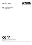
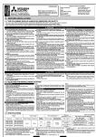
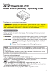
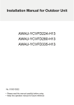
1
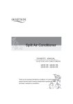
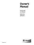
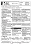
@ 2012 Trane All righte reserved. 3097844 Intertek CONFORMS TO UL STD. 1995 CERTIFIED TO CSA STD. C22.2 N0. 236 March 2012 6612991xxxx The manufacturer has a policy of continuous product and product data improvement and reserves the right to change design and specifications without notice. Only qualified technicians should perform the installation and servicing of equipment referred to in this manual. Supersedes Date Literature Order Number MS-SVN$-EN March 2013 4MXD8521A10N0AA 4MXD8524A10N0AA 4MXD8518A10N0AA 4MXD8512A10N0AA 4MXD8509A10N0AA 'XFW7\SHModel : 06SV1$(1 09,000 Btu/h to 24,000 Btu/h Multi Split Inverter System $LU+DQGOHUIRU ,QVWDOOHU¶V0DQXDO Warnings and Cautions Warnings and Cautions. Notice that warnings and cautions appear at appropriate intervals throughout this manual. Warnings are provided to alert installing contractors to potential hazards that could resullt in personal injury or death, while cautions are designed to alert personnel to conditions that could result in equipment damage. Your personal safety and the proper operation of this machine depend upon the strict observance of these precautions. Attention: Warnings and Cautions appear at appropriate sections throughout this literature. Read these carefully. WARNING: Indicates a potentially hazardous situation which, if not avoided, could result in death or serious injury. CAUTION: Indicates a potentially hazardous situation which, if not avoided, could result in minor or moderate injury. It may also be used to alert against unsafe practices. NOTICE: Indicates a situation that could result in equipment or property-damage only accidents. WARNING This equipment is to be serviced by professionally trained personnel ONLY. Under NO circumstances should an unqualified person service it. This equipment contains refrigerant under PRESSURE and operates at HIGH VOLTAGE. Improperly installed, adjusted or altered equipment by an unqualified person poses safety hazards including FIRE, ELECTROCUTION, or EXPLOSION, which could result in death or serious injury. WARNING Electrocution and Fire Hazards with Improperly Installed and Grounded Field Wiring! Improperly installed and grounded field wiring poses FIRE & ELECTROCUTION hazards. To avoid these hazards, you MUST follow requirements for field wiring installation and grounding as described in the National Electrical Codes (NEC) and your local/ state electrical codes. All field wiring MUST be performed by qualified personnel. Failure to follow these requirements could result in death or serious injury. Notice The total capacity of the indoor units which runs at the same time can not exceed 150% of that of outdoor units; otherwise, the cooling (heating) effect of each unit would be reduced. A breaker (or fuse) needs to be installed in every indoor unit, and the capacity should be in accordance with indoor unit’s electrical parameter; all indoor units are required to be controlled by a main switch, this switch can cut off the electric power supply in case of emergency. The breaker (or fuse) on each indoor unit has the function of preventing a short circuit and avoiding abnormal overload, it should be connected in a normal situation. The main switch controls the power supply to all of the indoor unitsDŽBefore cleaning and maintaining the indoor units, it is very important to turn off the main power supply switch. In order to turn on the units successfully, the main power switch should be applied 8 hours before the operation. It is normal for the indoor unit to still run for 20- 70 seconds after the indoor unit receives the "stop" signal so as to make full use of any remaining heated or cooled air. When the running modes of the indoor and outdoor units conflict, it will be indicated on the display of the control panel for five seconds and the indoor unit will stop. At this time, change the operation mode of the indoor unit to the one that would not conflict with the outdoor operating mode to make the operation normal. The HEAT mode will conflict with the COOL mode, DRY mode and FAN mode, while the COOL mode, DRY mode and FAN mode are compatible between each other. The appliance shall not be installed in moist places, such as the laundry, kitchen or bathroom. Power supply fluctuating range (+/-10%, +/-1Hz) . Humidity range: 30%~95%. Main switch is provided by the end user: and must comply with National, State and/or Local Codes. The instruction of the main power switch should be included in the user manual The cooling range of the unit is the outdoor ambient temp 0-110 F(-17~43 ć) DB, the heating range of the unit (only for the heat pump type unit) is the outdoor ambient temp. 5-75 F (-15~24ć) DB. This appliance is not intended for use by persons (including children) with reduced physical, sensory or mental capabilities, or lack of experience and knowledge, unless they have been given supervision or instruction concerning use of the appliance by a person responsible for their safety. Children should be supervised to ensure that they do not play with the appliance. This product must not be disposed with domestic waste. This product must be disposed at an authorized place for recycling of electrical and electronic appliances. Thank you for selecting this product. Before use of this product, please read this instruction manual carefully and keep it for future reference. Contents 1 Safety Precautions .......................................................................................... 1 2 Installation Location and Matters Needing Attention ....................................... 2 2.1 How to select the Installation Location for the indoor unit..................................... 2 2.2 Electric Wiring ....................................................................................................... 2 2.3 Grounding Requirements ..................................................................................... 3 2.4 Accessories for Installation ................................................................................... 3 3 Installation Instructions ................................................................................... 4 3.1 Outline Dimension Drawings of the Indoor Unit ................................................... 4 3.2 Dimension Requirements on the Installation Space of the Indoor Unit................. 4 3.3 Installation of the Indoor Unit ................................................................................ 5 3.4 Leveling the Indoor Unit ....................................................................................... 6 3.5 Installation of the Air Supply Duct ......................................................................... 6 3.6 Drawings of the Air Supply Outlet and Return Air Inlet ......................................... 7 3.7 Installation of the Return Air Duct ......................................................................... 8 3.8 Installation of the Condensate Pipe ...................................................................... 9 3.9 Design of the Drain Pipe ....................................................................................... 9 3.10 Installation of the Drain Pipe ............................................................................. 10 3.11 Precautions for the Lift Pipe .............................................................................. 11 3.12 Test for the Drainage System ............................................................................ 11 3.13 Piping ................................................................................................................ 12 3.14 Insulation for the Refrigerant Pipe .................................................................... 12 3.15 Wiring between the Wire and the Wiring Terminal ............................................ 13 3.16 Wiring of the Power Cord (single-phase) .......................................................... 14 3.17 Wiring of the Signal Line of the Wired Controller .............................................. 16 3.18 Electric Installation ............................................................................................ 16 4 Working Temperature Range......................................................................... 17 5 Error Analysis ................................................................................................ 18 6 Maintenance .................................................................................................. 19 1 Safety Precautions Read this manual carefully before using this unit, and operate it correctly according to the instructions in this manual. Pay special attention to the meaning of these two marks: Warning!: Indicates a potentially hazardous situation which, if not avoided, could result in death or serious injury. Notice!: Indicates a situation that could result in equipment or property-damage. Warning! ƹ Do not adopt fuse with unsuitable capacity or adopt iron thread instead of fuse, otherwise malfunction RU¿UHPD\KDSSHQ. ƹ Turn off the main power switch immediately if a malfunction is detected. ƹKeep good ventilation in the room to avoid oxygen deficit. ƹDo not LQVHUW¿QJHURUVWLFNOLNHobjectsLQWRGLVFKDUJHYHQWRURXWOHWJULOO ƹ Wall structure must be adequate to support the weight of the unit. Failure to ensure adequate structural support could result in the unit falling from its location which could result in death, serious injury, or equipment and/or property damage. ƹDo not apply sprays, paints, or insecticides to the surface of the unit as this is a fire hazard. ƹDo not attempt to repair, replace or relocate the unit. Contact your authorized dealer or installation professional for service, replacement or relocation of the unit. Install a separate disconnect at the outdoor unit. The power supply, wiring and grounding of equipment must comply with National, State and/or Local Codes. The power supply must agree with the equipment nameplate. Notice!: ƹBefore using the unit, please check to ensure the piping and wiring are correct to avoid water leakage, refrigerant leakage, electric shock, or fire, etc. ƹ The main power supply must be grounded to avoid the hazard of electric shock. Never connect this ground wire to the gas pipe, running water pipe, lightening rod or phone cable's ground lead. ƹ Turn off the unit after it runs at least five minutes; otherwise its service life will be shortened. ƹ Do not allow children to operate the air conditioner. ƹ Do not operate the unit while wet or if standing in water. ƹ3OHDVHWXUQRIIWKHPDLQSRZHUtoWKHXQLWEHIRUHFOHDQLQJWKHunit or changing WKH¿OWHU ƹ Please cut off the main power if the unit will not be used for an extended time. 1 Duct Type Air Handler 2 Installation Location and Matters Needing Attention This unit should only be installed and serviced by licensed technicians and electricians. Please contact your installing/servicing dealer for assistance. Installation quality will directly affect the normal use of the air conditioner. Do not attempt to install the air conditioner by yourself. Do not connect to power until all installation work is completed. 2.1 How to select the Installation Location for the indoor unit (1). Where there is no direct sunlight. (2). Where the top hanger, ceiling and the building structure are strong enough to withstand the weight of the unit. (3). Where the drain pipe can be easily connected to outside. (4). :KHUHWKHÀRZRIWKHDLULQOHWDQGRXWOHWDUHQRWEORFNHG (5). Where the refrigerant pipe of the indoor unit can be easily led to outside. (6). :KHUHWKHUHLVQRÀDPPDEOHH[SORVLYHVXEVWDQFHVRUWKHLUOHDNDJH (7). Where there is no corrosive gas, heavy dust, salt mist, smog or moisture. CAUTION! A unit that is installed in the following environments will not function properly and will have, shortened service life. If unavoidable, contact the servicing/installing dealer. ķ Where there is too much oil. ĸWhere it is exposed to salt air/water or other corrosive substances. ĹWhere there is sulfur gas(like sulfur hot spring); ĺ Where there are devices with high frequency (like wireless devices, electric welding devices, or medical equipment); ĻSpecial circumstances. 2.2 Electric Wiring (1). The installation must be done in accordance with National, State and/or Local Codes. (2). Only the power cord with the rated voltage and exclusive circuit for the air conditioner can be used. (3). Do not pull the power cord by force. (4). The electrical installation should be carried out a licensed electrician as instructed by National, State and/or Local Codes and also this manual. (5). The diameter of the power cord should be large enough and if it is damaged it must be replaced by the installing/servicing technician. 2 Duct Type Air Handler (6). The unit should be grounded properly and the ground wire should be connected to the dedicated device of the building by the technician. The power supply, wiring and grounding of equipment must comply with National, State and/or Local Codes. The power supply must agree with the equipment nameplate.. 2.3 Grounding Requirements (1). 7KHDLUFRQGLWLRQHULVFODVVL¿HGLQWR&ODVV,DSSOLDQFHVitmust be grounded properly (2). The yellow-green line of the air conditioner is the ground wire and can not be used for other purposes, cut off or fixed by the tapping screw; otherwise it would cause an electric shock hazard. (3). The required grounding terminal should be provided and the ground wire can not be connected to any of the following places˖ ķ Running water pipe; ĸ Coal gas pipe; Ĺ Sewage pipe; ĺ Other places where the technician determines unreliable. 2.4 Accessories for Installation Refer to the packing list for the accessories of the indoor and outdoor units respectively. 3 Duct Type Air Handler 3 Installation Instructions 3.1 Outline Dimension Drawings of the Indoor Unit 1RWHWKHXQLWLQWKHIROORZLQJV¿JXUHVLVPPXQOHVVRWKHUZLVHVSHFL¿HG )LJLVDSSOLFDEOHWRthe specific models referenced. G Electric Box liquid Pipe Gas Pipe Backward Return Air I H E Drain Pipe A Downward Return Air F J D B C Fig.1 Table 1: Outline Dimensions $ 0;'$1$$ 0;'$1$$ 0;'$1$$ 0;'$1$$ 0;'$1$$ % & ' ( ) * + , - PP PP PP PP PP PP PP PP PP PP LQFK LQFK LQFK LQFK LQFK LQFK LQFK LQFK LQFK LQFK PP PP PP PP PP PP PP PP PP PP LQFK LQFK LQFK LQFK LQFK LQFK LQFK LQFK LQFK LQFK PP PP PP PP PP PP PP PP PP PP LQFK LQFK LQFK LQFK LQFK LQFK LQFK LQFK LQFK LQFK 3.2 Dimension Requirements on the Installation Space of the Indoor Unit Nut with washer Spring pad ˚500 mm >19.7 inch ˚250 mm Fig. 2 4 >9.8 inch Duct Type Air Handler 3.3 Installation of the Indoor Unit (1). Requirements for the Installation Location 1) Ensure the hanger is strong enough to withstand the weight of the unit. 2) The drainage pipe is easily connected. 1RREVWDFOHLVLQWKHLQOHWRXWOHWDQGWKHDLUFLUFXODWLRQLVadequate 4) Ensure the installation space shown in Fig.2 is adequate for maintenance access.. ,WVKRXOGEHIDUDZD\IURPKHDWVRXUFHsOHDNDJHRIflammableH[SORVLYH substances, or smog. 6) It is the ceiling type unit (concealed in the ceiling). 7) The power cords and connection lines of the indoor and outdoor units must be at least 3.5 feet (1 m) away from the TV set or radio to avoid the image interference and noise ( even if the distance is kept, the noise may be produced due to the strong electromagnetic wave). (2). Installation of the Indoor Unit Insert the M10 expansion bolt into the hole, and then knock the nail into the bolt. Refer to the Outline Dimension Drawings of the Indoor Unit for the distance between holes and see Fig.3 for the installation of the expansion bolt. Hanger bolt Air conditioning unit Anchor Fig.3 Fig.4 Install the hanger on the indoor unit, as shown in Fig.4. Install the indoor unit on the ceiling, as shown in Fig.5. İ48mm İ2 inch Fig.5 CAUTION! ķ Prior to installation, make preparation for all piping (refrigerant pipe, drain pipe) and wiring (wires of the wired controller, wires between the indoor and outdoor unit) of the indoor unit to make installation more efficient. 5 Duct Type Air Handler ĸ ,IWKHUHLVDQRSHQLQJLQWKHFHLOLQJLWLVEHWWHUWRUHLQIRUFHLWWRNHHSLWÀDWDQGSUHYHQW vibration. Consult the user and builder for more details. Ĺ If the strength of the ceiling is not strong enough, a beam made of angle iron can be used DQGWKHQ¿[WKHXQLWRQLW ĺ If the indoor unit is not installed in an air conditioned area, please use foam wrap around the unit to prevent condensation. The thickness of the foam wrap depends on the actual installation environment. 3.4 Leveling the Indoor Unit After the installation of the indoor unit, the leveling must be checked to make sure the unit is kept horizontal fore and aft and keep a downward slope of 5° toward the drain pipe right and left, as shown in Fig.6. Check with a level Fig.6 3.5 Installation of the Air Supply Duct (1). Installation of the Rectangular Air Supply Duct 1 2 3 Return air 4 5 Return air 6 Supply air 3 7 8 Fig.7 Table 2 No. Name No. Name 1 Hanger 5 Plenum Box 2 Return Air Duct 6 Filter Screen 3 Canvas Duct 7 Main Air Supply Duct 4 Return Air Inlet 8 Air Supply Outlet (2). Installation of the Round Air Supply Duct 6 Duct Type Air Handler 1 2 4 5 6 7 8 3 Fig.8 Table 3 No. Name No. Name 1 Return Air Duct 6 Transition Duct 2 Canvas Duct 7 Air Supply Duct 3 Return Air Louver 8 Diffuser 4 Hanger 5 Air Supply Outlet (3). Installation Steps of the Round Air Supply Duct 1). Pre-installWKHRXWOHWRIWKHURXQGGXFWRQWKHWUDQVLWLRQGXFWDQGWKHQ¿[LWE\WKHWDSSLQJ screw. 2). 3ODFHWKHWUDQVLWLRQGXFWWRWKHDLURXWOHWRIWKHXQLWDQG¿[LWZLWKULYHW 3). Connect the outlet to the duct and then tighten them with tape. Other installation details are not covered herein. CAUTION! ķ The maximum length of the duct means the maximum length of the air supply duct plus the maximum length of the return air duct. The maximum length is no longer than 3.3 ft (1 m). ĸ 7KHGXFWLVHLWKHUUHFWDQJXODURUURXQGDQGFRQQHFWHGZLWKWKHDLULQOHWRXWOHWRIWKHLQGRRU unit. Among all air supply outlets, at least one should be kept open. As for the round duct, it needs DWUDQVLWLRQGXFWRIZKLFKWKHVL]HVKRXOGPDWFKZLWKWKHDLUVXSSO\RXWOHWRIWKHXQLW$IWHUWKH¿WWLQJ of the transition duct, it is the turn of the round duct, which is better to be kept 3.3 feet (1 meters) away from the corresponding diffuser. The standard accessories supplied by the manufacturer is the transition duct 7.9 inches (200 mm)ORQJDQGURXQGDLURXWOHWij7.9 inches (200 mm)KRZHYHU those of other specifications can be purchased. 7 7 Duct Type Air Handler 3.6 Drawings of the Air Supply Outlet and Return Air Inlet 21 D A B C Fig.9 Air Supply Outlet Fig.10 Return Air Inlet Table 4 Dimensions of the Air Supply Outlet and Return Air Inlet (unit: mm / inch) $LU6XSSO\2XWOHW 5HWXUQ$LU,QOHW $ % & ' 0;'$1$$ PP PP PP PP 0;'$1$$ LQFK LQFK LQFK LQFK PP PP PP PP LQFK LQFK LQFK LQFK 0;'$1$$ PP PP PP PP 0;'$1$$ LQFK LQFK LQFK LQFK 0;'$1$$ 3.7 Installation of the Return Air Duct (1). 7KHGHIDXOWLQVWDOODWLRQORFDWLRQRIWKHUHFWDQJXODUÀDQJHLVLQWKHEDFNDQGWKHUHWXUQDLU cover plate is in the bottom, as shown in Fig.11. Rectangular Flange Backward Return Air Downward Return Air Return Air Cover Plate Fig.11 (2). ,IGRZQZDUGUHWXUQDLULVGHVLUHGMXVWFKDQJHWKHSODFHRIWKHUHFWDQJXODUÀDQJHDQG the return air cover plate. (3). Connect one end of the return air duct to the return air outlet of the unit by rivets and the other to the return air louver. For the sake of convenience to freely adjust the height, a cutting of canvas duct will be helpful, which can be reinforced and folded by ˔ʿ iron wire. (4). More noise is likely to be produced in the downward return air mode than the backward UHWXUQDLUPRGHVRLWLVsuggestedWRLQVWDOOsound insulationDQGDSOHQXPER[WR minimize the noise. (5). The installation method can be chosen with considering the conditions of the building and maintenance etc., as shown in Fig.12. 8 Duct Type Air Handler 4 6 5 4 5 3 2 Air supply 1 Air supply 1 Return air Return air Install the return air pipe (a) Install the return air pipe(b) Fig.12 Table 5 Parts and Components of the Return Air Duct No. Name No. Name 1 5HWXUQ$LU/RXYHUZLWKWKH¿OWHUVFUHHQ 4 Indoor Unit 2 Canvas Duct 5 Air Supply Duct 3 Return Air Duct 6 Access Grille 3.8 Installation of the Condensate Pipe (1). The condensate pipe should keep a downward sloping angle of 5 ̚ 10 °, which can facilliate the drainage of the condensate water. And the joints of the condensate pipe should be insulated by insulation material to prevent condensation(see Fig.13). Insulating Layer for the Condensate Pipe Pipe Lip Fig.13 Thermal Insulation of the Condensate Pipe (2). 7KHUHLVDFRQGHQVDWHRXWOHWRQERWKOHIWDQGULJKWVLGHVRIWKHXQLW2QFHRQHLVFRQ¿UPHG to be used, the other should be sealed by a rubber plug, bundled by binding wire and insulated by insulation material to avoid water leakage. (3). The right outlet is defaulted to be sealed with a plug. CAUTION! Seal properly and verify there is no water leakage from the joint of the condensate pipe. Failure to do so may result in equipment and/or property damage. 3.9 Design of the Drain Pipe (1). 7KHGUDLQSLSHVKRXOGDOZD\VNHHSDdownward slopingDQJOH5 ~ 10 WRDYRLGZDWHU accumulation or improper drainage. (2). When connecting the drain pipe to the unit, avoid excessive force on the connection. The o o pipe should be as close to the unit as possible. (3). The drain pipe can be ordinary hard PVC pipe which can be purchased locally. During the connection, inset the end of the PVC pipe to the drain outlet, then tighten it with the drain hose and binding wire but never connect the drain outlet and the drain hose by adhesive. 9 Duct Type Air Handler (4). When the drain pipe is used for multiple devices, the joined section of the pipe should be 3.9 inches (100 mm) lower than the drain hole of each device and it is suggested to use a larger diameter pipe for such a purpose. 3.10 Installation of the Drain Pipe (1). The diameter of the drain pipe should be larger than or equal to that of the refrigerant pipe (PVC pipe, outer dimater:1 inch (25 mm), wall thickness ı0.05 inches (1.5 mm). (2). 7KHGUDLQSLSHVKRXOGEHDVVKRUWDVSRVVLEOHDQGZLWKDWOHDVWDGHJUHHRIVORSHWR avoid forming air pockets. (3). If the proper degree of slope of the drain pipe is not allowed, a lift bracket should be installed. (4). A distance 39.4 to 59 inches (1 to 1.5 m) should be kept between the hangers to avoid the drain hose sagging or bending. 1~1.5m 39.4-59 inch 5LJKWZLWKDPLQGHJUHHRIVORSH (Wrong) Fig.14 (5). Insert the drain hose into the drain hole and tighten it with clamps. (6). Insert drain pipe into opposite end of drain hose and clamp securely. Do not use adhesive at this joint. (7). Wrap the clamps with large amount of foam wrap for thermal insulation. (8). The drain hose inside the room also should be insulated. Clamp (accessory) Foam wrap (accessory) Clamp (accessory) Foam wrap (gray) Drain Hose Fig.15 10 Max. 4mm 0.16 inch Duct Type Air Handler 3.11 Precautions for the Lift Pipe The installation height of the lift pipe should be less than 33.5 inches (850 mm). It is recommended to set an inclination angle 1° ̚ 2° for the lift pipe toward the drainage direction. If the lift pipe and the unit form a right angle, the height of the lift pipe must be less than 31.5 inches (800 mm). 1~1.5m (3.3 - 4.9 feets) Hanger Bracket İ39.4 inch İ1000mm İ33.5 inch 6 inch İ850mm 150mm İ11.8 inch İ300mm Lift Pipe Drain Hose (accessory) ķ Ceiling 1°̚2° ĸClamp (accessory) Fig. 16 Notes: ķ The connection height of the drain hose should be within 33.5 inches (850 mm) so that the outlet of the drain hose does not suffer the external force. ĸ If multiple drain pipes converge, please follow the installation steps below. I - Joint of drain pipe Max.3 inch Max.75mm Max.39.4 inch Max.1000mm The specification of the joint of the drain pipe should be suitable to the running capacity of the unit Drain Hose (accessory) Fig.17 3.12 Test for the Drainage System (1). After the electrical installation, test the drainage system. (2). During the test, check if the water flow goes through the pipe correctly and observe 11 Duct Type Air Handler the joint carefully to see if it leaks or not. If this unit is installed in a newly built house, it is suggested to perform this test prior to the ceiling installation. 3.13 Piping (1). /HWWKHÀDUHHQGRIWKHFRSSHUSLSHSRLQWDWWKHVFUHZDQGWKHQWLJKWHQWKHVFUHZE\KDQG (2). Tighten the screw with a torque wrench until it is tightened sufficiently (as shown in Fig.18). Pipe Flare Nut Pipe Spanner Fig.18 Table 6 Moments of Torque for Tightening Screws 3LSH'LDPHWHU 5HTXLUHG7RUTXH ˳PP˳LQFK 1PIWOEI ˳PP˳LQFK 1PIWOEI ˳PP˳LQFK 1PIWOEI ˳PP˳LQFK 1PIWOEI (3). The bending degree of the pipe can not be too small; otherwise it will crack. Use a pipe tube bender to bend the pipe. (4). Wrap the exposed refrigerant pipe and the joints with foam wrap and then secure it with plastic tape. CAUTION! ķ During the connection of the indoor unit and the refrigerant pipe, never pull any joints of the indoor unit by force; otherwise the capillary pipe or other pipe may crack, which then would result in leakage. ĸ The refrigerant pipe should be supported by brackets, don’t let the unit withstand the weight of it. ,IWKHVSHFL¿FDWLRQRIWKHRXWGRRUXQLWSLSHMRLQWGRHVQRWFRQIRUPWRWKDWRIWKHLQGRRUXQLWWKHQ WKHMRLQWVSHFL¿FDWLRQRIWKHRXWOHWSLSHRIWKHLQGRRUXQLWWDNHVSUHFHGHQFH$UHGXFLQJQLSSOHVKDOO be installed at the joint of the outdoor unit so as to make the joint of the outdoor unit compatible with that of the indoor unit. 3.14 Insulation for the Refrigerant Pipe (1). The refrigerant pipe should be insulated by insulating material and plastic tape in order to prevent condensation and water leakage. (2). The joints of the indoor unit should be wrapped with insulating material and no gap is 12 Duct Type Air Handler allowed on the joint of the indoor unit, as shown in Fig.19. No gap Fig.19 CAUTION! After the pipe is protected well enough, never bend it to form a small angle; otherwise it would crack or break. (3). Wrap the pipe with tape. 1). Bundle the refrigerant pipe and electric wire together with tape, and separate them from the GUDLQSLSHWRSUHYHQWWKHFRQGHQVDWHZDWHURYHUÀRZLQJ 2). Wrap the pipe from the bottom of the outdoor unit to the top of the pipe where it enters the wall. During the wrapping, the later circle should cover half of the former one. 3). Fix the wrapped pipe on the wall with clamps. CAUTION! ķ Do not wrap the pipe too tightly; otherwise the insulation effect would be reduced. Additionally, make sure the drain hose is separated from the pipe. ĸ FillWKHKROHinWKHZDOOZLWKVHDOLQJPDWHULDOWRSUHYHQWZLQGDQGUDLQFRPLQJLQWR the room. 3.15 Wiring between the Wire and the Wiring Terminal (1). Wiring of the Single-Core Wire (solid wire). 1). Strip the insulating layer at the end of the wire about 1 inch (25 mm) off with a wire striper. 2). Loosen the screw on the wiring board of the air conditioning unit. 3). Shape with pliers at the end of the wire to a circle matching with the size of the screw. 4). /HWWKHVFUHZJRWKURXJKWKHFLUFOHRIWKHZLUHDQGWKHQ¿[LWRQWKHZLULQJERDUG (2). Wiring of the Multi-Core Wire (stranded wire). 1). Strip the insulating layer at the end of the wire about 4 inches (100 mm) with a wire stripper. 2). Loosen the screw on the wiring board of the air conditioning unit. 3). Fix a wiring terminal matching the size of the screw to the end of the multi-core wire with crimping pliers. 4). /HWWKHVFUHZJRWKURXJKWKHWHUPLQDORIWKHPXOWLFRUHZLUHDQG¿[LWRQWKHZLULQJ board. 13 Duct Type Air Handler A.Single-Cored Wire B.Mulit-Cored Wire Wiring Terminal 25 mm 1 inch 10 mm 0.4 inch Insulating layer Fig.20 WARNING! ķ If the power cord or the signal line are damaged, they must be replaced with the required replacement part. ĸ Prior to wiring, please check the voltage marked on the nameplate and carry out the wiring following the wiring diagram. Ĺ The dedicated power cord must be used for the air conditioning unit and the electrical leakage protection switch and air switch must be installed in case of an overload condition. ĺ The air conditioning unit must be grounded to prevent hazard caused by failed insulation. Ļ During wiring, the wiring terminal or single-core wire must be used; the direct wiring EHWZHHQWKHPXOWLFRUHZLUHDQGZLULQJERDUGcouldFDXVH¿UH ļ All wiring should be done strictly in accordance with the wiring diagram; otherwise improper wiring would cause abnormal operation or damage to the unit.. Ľ Do not let the electric wires touch the refrigerant pipe, the compressor, the fan or other moving parts. ľ Do not modify the wiring inside the indoor unit ; otherwise the manufacturer will not assume any responsibility for the damage or abnormal operation of the unit. 3.16 Wiring of the Power Cord (single-phase) CAUTION! The power supply for each indoor unit must be uniform. ķ Dismantle the cover of the electric box of the indoor unit. ĸ Let the power cord go through the rubber ring. Ĺ Put the 4-core cable through the hole of the chassis and the bottom of the appliance upward, and then connect the power line and the communication line from the outdoor unit to the corresponding terminals N(1), 2, 3 , and grounding terminal of the indoor unit. Wiring shall be done properly as per the wiring diagram. (Note: Be sure the wiring terminals $%&' DQG SLSLQJ MRLQWV$%&' RI WKH LQGRRU XQLW PDWFK ZLWK WKDW RI WKH RXWGRRU XQLW respectively). ĺ Fix the power cord tightly with a plastic wire tie. 14 Duct Type Air Handler For example: wiring connection for 4TXM6542A1050BA INDOOR UNIT E XT6 G INDOOR UNIT D XT5 G G INDOOR UNIT B XT3 G INDOOR UNIT A XT2 G L N POWER Fig.21 15 XT1 OUTDOOR UNIT INDOOR UNIT C XT4 Duct Type Air Handler 3.17 Wiring of the Signal Line of the Wired Controller (1). Open the cover of the electric box of the indoor unit. (2). Let the signal line go through the rubber ring. (3). Insert the signal line to the four-pin socket on the printed circuit board of the indoor unit. (4). Fix the signal line with a plastic wire tie. 3.18 Electric Installation Table 7 Type Model Power Supply 4MXD8509A10N0AA Running Current (A) Input Power (W) Recommended Power Cord Indoor Fan Motor Cooling Heating (Sectional Area x Pieces) 208/230V~60Hz 0.28 80 80 AWG 14 X 4 4MXD8512A10N0AA 208/230V~60Hz 0.31 80 80 AWG 14 X 4 4MXD8518A10N0AA 208/230V~60Hz 0.41 100 100 AWG 14 X 4 4MXD8521A10N0AA 208/230V~60Hz 0.5 124 124 AWG 14 X 4 4MXD8524A10N0AA 208/230V~60Hz 0.5 124 124 AWG 14 X 4 Cooling and Heating Notes: The sectional area listed above is applicable to the power cord with a maximum length of 49.2 feet (15 meters). For the longer cord, its sectional area should be enlarged to avoid the cord burning out caused by over-current. 16 Duct Type Air Handler 4 Working Temperature Range Table 8 Working Temperature Range Outdoorside DB( F ) 110 0 75 5 Maximum cooling Minimum cooling Maximum heating Minimum heating 17 Duct Type Air Handler 5 Error Analysis If your conditioning unit runs abnormally, please check the following items before contacting the maintenance serviceman. Table 9 Errors Failed startup Stop after a short while of operation Possible Causes No power supply. Breaker opens due to electrical leakage. Voltage is too low. Air LQOHWRXWOHWRIWKHLQGRRURXWGRRUXQLWLVFORJJHG Poor cooling effect AirU¿OWHUVFUHHQLVWRRGLUW\RUFORJJHG Too many heat sources or people in the room. Door or window is open. ObstaclesDWWKHDLULQOHWRXWOHW Set temperature is too high. Poor heating effect Air¿OWHUVFUHHQLVWRRGLUW\RUFORJJHG Door or window is not closed fully. Set temperature is too low. Unresponsive controller If the remote controller fails even if the batteries have been replaced, please open the back cover of it and press the button “ACL” to reset it back to the normal condition. Is the remoter controller in the signal receiving range? Or is it blocked by obstacles? For the duct type unit, operate the remote controller pointing at the wired controller. If the above remote control steps fail, make sure the wired controller also has new batteries.. Note: If the air conditioner still runs abnormally after checking the above , please contact the installing/servicing dealer for assistance. 18 Duct Type Air Handler 6 Maintenance CAUTION! Take notice of the following items before cleaning your air conditioning unit. (1). Cut off the main power supply before contacting any wiring device. (2). Only when the unit is turned off and the main power supply is cut off, can the unit be cleaned; otherwise it could cause electric shock or injury. (3). Do not wash the unit with water; or it may cause an electric shock. (4). During cleaning, remember to use a stable standing platform . Daily Maintenance 1). +RZWRFOHDQWKH¿OWHU ķ 1HYHUGLVPDQWOHWKHDLU¿OHUH[FHSWIRUFOHDQLQJRWKHUZLVHLWPD\FDXVHanHUURU ĸ :KHQWKHDLUFRQGLWLRQLQJXQLWLVXVHGin anHQYLURQPHQWZLWKKHDY\GXVWWKHDLU¿OWHU should be cleaned often (generally once every two weeks). 2). Maintenance before seasonal use ķ &KHFNLIWKHDLULQOHWRXWOHWRIWKHLQGRRUXQLWLVFORJJHG ĸ Check if the grounding is in good condition. Ĺ Check if the wiring is in good condition. ĺ Check if the indicating lamp of the wired controller blinks after it is energized. Note: If there is something abnormal, please consult the servicing/installing dealer. 3). Maintenance after seasonal use ķ Let the air conditioning unit run for half day under the fan mode to dry the inside of the unit. ĸ If the unit is not to be used for a long time, please shut off the main power supply for energy conservation, at the same time, the power indicating lamp of the wired control will go off. 19