1
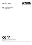
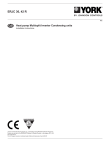
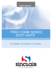
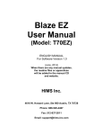
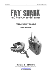
USER'S MANUAL
MULTI COMBI SERIES
DUCT MC-D09,12,18,21,24AI
User Notice
◆ The total capacity of the indoor units which runs at the same time can not exceed 150% of
that of the outdoor units; otherwise, the cooling (heating) effect of each indoor unit would be poor.
◆ Switch the main power on 8 hours before start the unit, helpful for a successful startup.
◆ It is a normal phenomenon that the indoor unit fan will still run for 20~70 seconds after the
indoor unit receives the “stop” signal so as to make full use of after-heat for the next operation.
◆ When the running modes of the indoor and outdoor units conflict, it will be indicated on
the display of the wired controller in five seconds and then the indoor unit will stop. In this case,
they can back to the normal condition by harmonizing their running modes: the cooling mode is
compatible with the dehumidifying mode and the fan mode can go with any other mode. If the
supply power fails when the unit is running, then the indoor unit will send the “start” signal to the
outdoor unit three minutes later after power recovery.
◆ During installation, the communication cable and the power cord must not be twisted
together but instead separated with an interval of at least 2cm; otherwise the unit is likely to run
abnormally.
This product must not be disposed together with the domestic waste. This product
has to be disposed at an authorized place for recycling of electrical and electronic
appliances.
Thank you for purchasing Sinclair air conditioners. Before use, please read this manual
carefully and keep it properly for further reference.
Wired Controller XK19
Ⅰ Wired Controller XK19
1 Wired Controller XK19
It is optional for the cassette type, wall-mounted, and floor ceiling indoor units.
1.1 Outside View of the Wired Controller
Fig.1 Outside View of the Wired Controller
1.2 LCD of the Wired Controller
Fig.2 LCD of the Wired Controller
1
Wired Controller XK19
1.3 Introduction to the Symbols on LCD
Table 1
No.
Symbols
Description
1
Swing function.
2
Sleep function (3 types: sleep 1,sleep2 and sleep 3).
3
Running modes of the indoor unit (Cooling, Dry, Fan and Heating).
4
Defrosting function for the outdoor unit.
5
Gate-control function (this function is yet unavailable for this unit).
6
Lock function.
7
High, middle, low or auto fan speed of the indoor unit.
8
SHIELD
Shield functions (buttons, temperature, On/Off, Mode or Save is shielded or
Save is shielded by the remote monitor.
9
TURBO
Turbo function.
10
MEMORY
Memory function (The indoor unit resumes the original setting state after
power failure and then power recovery).
11
MASTER
Master wired controller (this function is yet unavailable for this unit).
It blinks under on state of the unit without operation of any button.
12
13
SAVE
Energy-saving function.
Ambient/preset temperature value.
14
15
E-HEATER
16
BLOW
Electric auxiliary heating function.
Blow function.
Timing value.
17
18
QUITE
Quiet function (two types: quiet and auto quiet).
19
SET
It will be displayed under the debugging mode.
2 Buttons
2.1 Buttons on the Wired Controller
Fig. 3 Buttons on the Wired Controller
2
Wired Controller XK19
2.2 Function of the Buttons
Table 2
No.
Name
1
Enter/cancel
2
▲
6
▼
3
Fan
4
Mode
5
Function
Function
① Function selection and cancellation.
② Press it for 5s to examine the outdoor ambient temperature.
① Running temperature setting of the indoor unit, range:16 ~ 30℃ .
② Timer setting, range:0.5-24 hr.
③ Switchover between quiet/auto quiet or among sleep1/sleep2/sleep 3.
Setting of the high/middle/low/auto fan speed.
Setting of the Cooling/Heating/Fan/Dry mode of the indoor unit.
Switchover among the functions of Swing/Sleep/Turbo/Save/E-heater/Blow /
Quiet etc.
7
Timer
Timer setting.
8
On/Off
Turn on/off the indoor unit.
4+2
▲+Mode
3 +6
Fan+▼
2 +6
▲+▼
Press them for 5s under off state of the unit to enter/cancel the Memory function
(If memory is set, indoor unit after power failure and then power recovery will
resume the original setting state. If not, the indoor unit is defaulted to be off after
power recovery. Memory off is default before delivery.).
By pressing them at the same time under off state of the unit, will be displayed
will be displayed on
on the wired controller for the cooling only unit, while
the wired controller for the cooling and heating unit.
Upon startup of the unit without malfunction or under off state of the unit,press
them at the same time for 5s to enter the lock state, in which case, any other
buttons won’t respond the press. Repress them for 5s to quit this state.
3 Operation Instructions
3.1 On/Off
Press On/Off to turn on the unit and turn it off by another press.
Note: The state shown in Fig.4 indicates the “Off” state of the unit after power on. The state shown in
Fig.5 indicates the “On” state of the unit after power on.
Fig. 4 “Off” State
Fig. 5 “On” State
3.2 Mode Setting
Under the “On” state of the unit, press Mode to switch the operation modes as the following sequence:
Cooling-Dry-Fan-Heating.
3
Wired Controller XK19
3.3 Temperature Setting
Press ▲or ▼ to increase/decrease the preset temperature. If press either of them continuously, the
temperature will be increased or decreased by 1℃ every 0.5s,as shown in Fig.6.
In the Cooling, Dry or Heating mode, the temperature setting range is 16℃~ 30℃ .
In the Fan mode, the setting temperature is fixed at 26℃ .
In the Auto mode, the setting temperature is unadjustable.
Fig.6
3.4 Fan Setting
Under the “On”/”Off” state of the unit, press Fan and then fan speed of the indoor unit will change
circularly as shown in Fig.7.
Auto
Low
Middle
High
Fig.7
3.5 Timer Setting
Under the “On”/”Off” state of the unit, press Timer to set timer off/on.
Timer on setting: press Timer, and then LCD will display “xx.x hour”, with “hour” blinking. In this case,
press ▲or ▼ to adjust the timing value. Then press Enter/cancel to confirm the setting.
Timer off setting: press Timer, if LCD won’t display xx.x hour, and then it means the timer setting is
canceled.
4
Wired Controller XK19
Timer off setting under the “On” state of the unit is shown as Fig.8.
Fig. 8 Timer off Setting under the “On” State of the Unit
Timer range: 0.5-24hr. Every press of ▲or ▼ will make the set time increased or decreased by 0.5hr. If
either of them is pressed continuously, the set time will increase/ decrease by 0.5hr every 0.5s.
3.6 Swing Setting
Swing On: Press Function under on state of the unit to activate the swing function. In this case,
blink. After that, press Enter/cancel to make a confirmation.
Swing Off: When the Swing function is on, press Function to enter the Swing setting interface, with
blinking. After that, press Enter/cancel to cancel this function.
Swing setting is shown as Fig.9.
5
will
Wired Controller XK19
Fig. 9 Swing Setting
Note:
① . Sleep, Save, Turbo, Blow or Quiet setting is the same as the Swing setting.
② . After the setting has been done, it has to press the key “Enter/cancel” to back to the setting status or
quit automatically five seconds later.
3.7 Sleep Setting
Sleep on: Press Function under on state of the unit till the unit enters the Sleep setting interface. Then
press ▲or ▼ to switch among Sleep 1, Sleep 2 and Sleep 3. After that, press Enter/cancel to confirm the
setting.
Sleep off: When the Sleep function is activated, press Function to enter the Sleep setting interface. After
that, press Enter/cancel to can this function.
Sleep setting is shown as Fig.10.
6
Wired Controller XK19
Fig. 10 Sleep Setting
Sleep off is default after power failure and then power recovery, and the sleep functions is unavailable
under the fan mode.
There are three Sleep modes: Sleep 1, Sleep 2 and Sleep 3.
a. Sleep 1
In the Cooling or Dry mode, the temperature will increase by 1℃ after the unit runs under Sleep 1 for 1hr
and 1℃ after another 1hr.After that, the unit will run at this temperature.
In the Heating mode, the temperature will decrease by 1℃ after the unit runs under Sleep 1 for 1hr and
1℃ after another 1hr. After that, the unit will run at this temperature.
b. Sleep 2
In the Cooling mode, the temperature may be set between 16 ℃ -23 ℃ , 24 ℃ - 27 ℃ or 28 ℃ - 29 ℃
or at 30 ℃ , and their Sleep curves are shown in Fig.11 (Note: The curve is only for reference, the actual
temperature is subject to the time point.).
For example: The temperature in the Cooling mode is set at 25 ℃ . Under the mode of Sleep 2, the
temperature will increase by 1℃ every 1hr. After it increases by 2℃ in total, it will keep at 27℃ . 7 hours
later, it will decrease by1℃ , i.e. 26℃ .After that, the unit will keep running at 26℃ .
7
Wired Controller XK19
(
T
e
m
p
/
)
℃
31
30
29
28
27
26
25
24
23
22
21
20
19
18
17
16
0
1
2
3
4
5
6
7
8
9
10
11
12
Time/(Hr)
Fig.11 Sleep Curve of Sleep 2 in Cooling Mode
In the Heating mode, the temperature may be set at 16℃ or between 17℃ - 20℃ , 21℃ -27℃ or 28℃ 30℃ and their Sleep curves are shown in Fig.12:
(
T
e
m
p
/
)
℃
31
30
29
28
27
26
25
24
23
22
21
20
19
18
17
16
0
1
2
3
4
5
6
7
8
9
10
11
12
T i m e /(H r )
Fig.12 Sleep Curve of Sleep 2 in Heating Mode
8
Wired Controller XK19
For example, the temperature in the Heating mode is set at 22 ℃ .Under the mode of Sleep2, the
temperature will decrease by 1 ℃ every 1hr. After it decreases by 2 ℃ in total, i.e. 20 ℃ ,the unit will keep
running at 20℃ .
c. Sleep 3
Sleep curve setting under Sleep 3(DIY mode)
d. Under the mode of Sleep 3, press Timer to enter the Sleep setting. In this case, “1 HOUR” is displayed
where the timing value once is displayed and the corresponding temperature with the last Sleep curve setting
is displayed where the ambient/preset temperature once in displayed.
e. Press ▲or ▼ to change the corresponding temperature setting.
f. Press Timer, time will automatically increase by 1hr, and the corresponding temperature with the last
Sleep curve setting is displayed where the ambient/preset temperature once is displayed.
g. Repeat step 2 and step 3 till 8 HOUR Sleep setting is finished.
h. Press Enter/cancel to confirm the setting.
Sleep curve setting under Sleep 3 is as shown in Fig.13.
Fig. 13 Sleep Curve Setting under Sleep 3
Notes:
① . During the above setting, if Function is pressed down or there is not any operation within 5s, sleep
curve setting will be canceled.
② . 26℃ is the default Sleep curve temperature before delivery. The wired controller will automatically
memorize the Sleep curve after the setting.
3.8 Turbo Setting
Turbo function: The unit at the high fan speed can realize quick cooling or heating so that the room
temperature can quickly approach the setting value.
In the Cooling or Heating mode, press Function till the unit enters the Turbo setting interface and then
press Enter/Cancel to confirm the setting.
9
Wired Controller XK19
When the Turbo function is activated, press Function to enter the Turbo setting interface and then press
Enter/Cancel to cancel this function.
Turbo function setting is as shown in Fig.14.
Fig.14 Turbo Setting
Notes:
① . When the Turbo function is activated, if the difference between the room temperature and set
temperature is at or below 2 ℃ (detected in successive 1 min.), the Turbo function will be automatically
deactivated.
② . Turbo function is unavailable in the Dry and Fan mode. And the Turbo function is off after power
failure and then power recovery. If Quiet function is on, Turbo function will be canceled subsequently.
3.9 Save Setting
Save: Energy saving which will result the air conditioner runs in smaller temperature range is realized by
setting lower limited value in the Cooling or Dry mode and upper limited value in the Heating mode.
Save Setting for Cooling:
Under the “On” state and in the Cooling or Dry mode of the unit, press Function to enter the Save setting
interface and then press ▲or ▼ to adjust the lower limited value in the Cooling mode. After that, press Enter/
Cancel to activate the Save function. The initial lower limited value in the Cooling mode is 26℃ .
When the Save function is activated, press Function to enter the Save setting interface and then press
Enter/cancel to cancel this function.
The Save setting for cooling is shown in the Fig.15
10
Wired Controller XK19
Fig. 15 Saving Setting for Cooling
Save Setting for Heating:
Under on state or in the Heating mode of the unit, press Function to enter the Save setting interface and
then press ▲or ▼ to adjust upper limited value in the Heating mode. After that, press Enter/Cancel to activate
the Save function for heating. The upper initial limited value in the Heating mode is 20℃ .
After the Saving function is activated, press Function to enter the Save setting interface and then press
Enter/Cancel to cancel this function.
Save setting for heating is as shown in Fig. 16
11
Wired Controller XK19
Fig.16 Save Setting for Heating
Notes:
① . If press Function on the Save setting interface or if there is not any operation for 5s after last button
press, the Save setting will be canceled automatically by the system, with memorizing the present setting data.
② . When power is on after the power failure, the Save function will be memorized.
3.10 E-heater Setting
E-heater (auxiliary electric heating function): In the Heating mode, E-heater is allowed to be turned on for
improvement of efficiency.
Once the wired controller or the remote controller enters the Heating mode, this function will be turned on
automatically.
Press Function in the Heating mode to enter the E-heater setting interface and then press Enter/cancel to
cancel this function.
Press Function to enter the E-heater setting interface, if the E-heater function is not activated, and then
press Enter/Cancel to turn it on.
The setting of this function is shown as Fig.17 below:
12
Wired Controller XK19
Fig.17 E-heater Setting
3.11 Blow Setting
Blow function: After the unit is turned off, the water in evaporator of indoor unit will be automatically
evaporated to avoid mildew.
In the Cooling or Dry mode, press Function till the unit enters the Blow setting interface and then press
Enter/Cancel to active this function.
When the Blow function is activated, press Function to the Blow setting interface and then press Enter/
Cancel to cancel this function.
Blow function setting is as shown in Fig.18
13
Wired Controller XK19
Fig.18 Blow Setting
Notes:
① . When the Blow function is activated, if turning off the unit by pressing On/Off or by the remote
controller, the indoor fan will run at the low fan speed for 10 min, with “BLOW” displayed on the LCD.
While, if the Blow function is deactivated, the indoor fan will be turned off directly.
② . Blow function is unavailable in the Fan or Heating mode.
3.12 Quiet Setting
Quiet function consists of two kinds: quiet and auto quiet.
Press Function till the unit enters the Quite setting interface, with “Quiet” or “Auto” blinking. In this case,
press ▲or ▼ to switch between Quiet and Auto and then press Enter/cancel to make a confirmation.
When the Quiet function is activated, press Function till the unit enters the Quite setting interface, with
“Quite” or “Auto” blinking. Then press Enter/cancel to cancel this function.
Quiet function setting is as shown in Fig.3.16:
14
Wired Controller XK19
Fig.19 Quiet Setting
Notes:
① . When the Quite function is activated, the fan speed is low and un-adjustable.
② . When the Auto Quite function is activated, the unit will run according to the difference between the
room temperature and the setting temperature. In this case, the fan speed is adjustable.
Difference between the room temperature and the setting temperature: the fan speed will keep its current
state if the temperature difference ≥ 4 ℃ ; the fan speed will reduce one grade if 2 ℃ ≤ the temperature
difference ≤ 3℃ ; the fan speed will be at min. grade if the temperature difference ≤ 1℃ .
③ . When the Auto Quiet function is on, the fan speed can not be raised but reduced. If the high fan speed
is manually adjusted, the function will quit automatically.
④ . There is not Auto Quiet function in the Fan or Dry mode. Quiet off is default after power failure and
then power recovery.
3.13 Other Functions
a. Lock
Upon startup of the unit without malfunction or under the “Off” state of the unit, press ▲ and ▼ at the
same time for 5s till the wired controller enters the Lock function. In this case, LCD displays . After that,
repress these two buttons at the same time for 5s to quit this function.
Under the Lock state, any other button press won’t get any response.
b. Memory
Memory switchover: Under the “Off” state of the unit, press Mode and ▲ at the same time for 5s to
switch memory states between memory on and memory off. When this function is activated, Memory will be
displayed. If this function is not set, the unit will be under the “Off” state after power failure and then power
recovery.
15
Wired Controller XK19
Memory recovery: If this function has been set for the wired controller, the wired controller after power
failure will resume its original running state upon power recovery. Memory contents: On/Off, Mode, set
temperature, set fan speed, Save function and Lock function.
c. Enquiry of the Outdoor Ambient Temperature
Under the “On” or “Off” state of the unit, press Enter/Cancel for 5s, and the outdoor ambient temperature
will be displayed after a sound of click. This enquiry state will quit by pressing Function or On/Off or during
the temperature adjustment. If there is not any operation for 10s, it will also quit automatically.
4 Errors
If there is an error occurring during the operation of the system, the error code will be displayed on the
LCD, as show in Fig.20. If multi errors occur at the same time, their codes will be displayed circularly.
Note: In event of any error, please turn off the unit and contact the professionally skilled personnel.
Fig.20
16
Wired Controller XK19
Table 3 Meaning of Each Error
Error Code
Error
High pressure protection
E1
Low pressure protection
E3
Discharge protection
E4
Over-current protection
P5
Communication error
E6
Indoor water overflow protection
E9
Mode conflict
E7
Anti-freezing protection
E2
Defrosting or oil returning for heating
H1
Indoor ambient temperature sensor open/short circuit
F1
Evaporator temperature sensor open/short circuit
F2
Indoor unit (liquid valve) refrigerant pipe inlet temperature sensor error
b5
Indoor unit (gas valve) refrigerant pipe outlet temperature sensor error
b7
Condenser coil inlet temperature sensor open/short circuit
A5
Condenser coil midway temperature sensor error
F4
Condenser coil outlet temperature senor open/short circuit
A7
Discharge air temperature sensor error
F5
Outdoor ambient temperature sensor error
F3
Module temperature sensor error
oE
Outdoor unit overall error
oE
17
Wireless Remote Controller YT1F
Ⅱ Wireless Remote Controller YT1F
Notes:
① . Be sure that there are no obstructions between the receiver and the remote controller;
② . Do not drop or throw the remote controller;
③ . Do not let any liquid into the remote controller and expose the remote controller to direct sunlight or
any place where is very hot.
④ . This is a general use remote controller. If press some button which is not available for the
corresponding function, the unit will keep the original running status.
1 Function of Press Buttons:
Note: This remote controller
is universal and can be used
for multi‐functional air
conditioning. If the button on
the remote controller with
the function which the air
conditioner doesn’t have is
pressed, the unit remains in
its original operating mode.
Fig.21
1) ON/OFF ( )
Press this button to turn on/off the unit. After that, the sleep function will be canceled but the preset time
is still remained.
2) MODE
Auto, Cool, Dry Fan, Heat modes can be selected circularly by pressing this button. Auto mode is the
default after power on. Under Auto mode, the temperature will not be displayed. Under Heat mode, the initial
value is 28℃ (82 ℉ ); Under other modes, the initial value is 25℃ (77 ℉ ).
3) SLEEP
Sleep On and Sleep Off can be selected by pressing this button. After powered on, the default is Sleep Off.
After the unit is turned off, the Sleep function is canceled. When the sleep function is set already, the symbol
will be displayed. And at this time, the time of timer can be adjusted. Under Fan and Auto modes, this
unction is not available.
18
Wireless Remote Controller YT1F
4) FAN
Auto, Low, Middle, or High fan speed can circularly selected by pressing this button. After powered on,
the default is Auto speed. Under Dehumidifying mode, only Low fan speed is available.
5) CLOCK
The clock can be set up by pressing this button, with the symbol
displayed and blinking. In such a
case, pressing + or - within 5 seconds can adjust the value. If the button is pressed down for more than 2
seconds, the value on ten’s place will increase by 1 in every 0.5 seconds. After that, repressing this button
and then symbol
stops blinking, which indicates the setting is made successfully. After powered on, the
default value is 12:00 with
displayed. Once the symbol
is displayed, the current time is the Clock value;
otherwise it is the Timer value.
6) LIGHT
Light On and Light Off can be set by pressing this button when the unit is at On or Off status. After
powered on, the default is Light On.
7) TURBO
In Cool or Heat mode, pressing this button can activate or deactivate this function. When this function
is on, its symbol will be displayed. Any change of either mode or fan speed will make this function canceled
automatically.
8) BLOW
BlOW On and BLOW Off can be set by pressing this button. In Cool and Dehumidifying modes, press
this button to activate this function and then “BLOW” will be displayed. After that, it can be canceled by
repressing this button. After powered on, the default is Blow Off. If the ON/OFF button is operated or the unit
is switched to the Cool or Dehumidifying mode, it will keep its original status. When the unit is turned off,
Only Blow Off is available. Under Auto, Fan or Heat mode, this function is unavailable.
9) -
The preset temperature can be decreased by pressing this button. If the button is pressed down for more
than 2 seconds, the temperature will be decreased quickly until it is released, with ℃ ( ℉ ) displayed al the
time. Under Auto mode, the temperature adjustment is unavailable.
10) +
The preset temperature can be increased by pressing this button. If the button is pressed down for more
than 2 seconds, the temperature will be increased quickly until it is released, with ℃ ( ℉ ) displayed all the
time. Under Auto mode, the temperature adjustment is unavailable. The setting range is 16-30 ℃ or 61-86 ℉
11) TEMP
It can be decided by pressing this button which temperature will be displayed, indoor set temperature, or
indoor ambient temperature. When the indoor unit is powered on, the indoor set temperature will be displayed,
, the indoor ambient temperature will be displayed. However, the indoor
while if the status is changed to
set temperature will be displayed again when the controller receives other remote controls signals. Without
setting this function, the default is the indoor set temperature.
12) SWING UP/DOWN ( )
The swing angle which circularly changes as below can be selected by pressing this button:
19
Wireless Remote Controller YT1F
This kind of remoter controller is universal. And the three swing statuses of
are the same
as that of
.
If the swing function is deactivated when the air guide louver is swing up and down, it will stop at the
current position.
indicates that the air guide louver swings up and down among all five positions.
13) AIR ( )
AIR ON or Air OFF can be selected by pressing this button.
14) TIMER ON
“ON” will be displayed and blink for 5 seconds by pressing this button, and soon adjust the time by
pressing + or - within 5 seconds. Each press will make the time increased or decreased by 1 minute. If
the button is pressed down for more than 2 seconds, the time will be changed quickly in such a way: firstly
the value on the one’s place is changed and then is the value on the ten’s place. Once Timer ON has been set
already, it can be canceled by repressing it. Before the setting, please adjust the CLOCK to the current actual
time.
15) TIMER OFF
TIME OFF can be activated by pressing this button, with “OFF” blinking. The method of setting is the
same as that for TIMER ON.
)
16) HEALTH (
This function can be activated or deactivated by pressing this button. After the unit is turned on, the
default is HEALTH ON.
17) I FEEL
This function can be activated by pressing this button and canceled by another press. When this function
is on, the I FEEL information will be sent out in 200ms after each operation on the controller and the remote
controller will send the temperature information to the main controller every 10 minutes.
2 Guide for General Operation
a. After powered on, press ON/OFF and then the unit will start to run. (Note: when powered off, the
guide louver of the main unit will close automatically).
b. Press MODE to select the desired running mode.
c. Press + or - to set the desired temperature (it is unnecessary to set the temperature under the AUTO
mode.)
d. Press FAN to set the fan speed, AUTO, LOW, MID, or HIGH.
e. Press
to select the swing angle.
3 Guide for Optional Operation
a. About BLOW
This function indicates that moisture in the evaporator of the indoor unit will be dried after the unit is
stopped to avoid mould.
① . BLOW ON: When press the ON/OFF button to turn off the unit, the indoor fan will continue running
for about another 10 minutes at the low speed. In this case, the indoor fan can be stopped directly by pressing
the button BLOW.
20
Wireless Remote Controller YT1F
② . BLOW OFF: When press the ON/OFF button to turn off the unit, the whole unit will be stopped
completely.
b. About AFTERHEAT BLOW
Under the Heat mode or Auto Heat mode, if the unit is turned off, the compressor and outdoor fan will
stop running immediately and the upper and lower guide board will rotate to the horizontal position, while the
indoor fan will still run at the low fan speed. Then, 10 seconds later, the unit will stop completely.
c. About AUTO RUN
When AUTO RUN is selected, the setting temperature will not be displayed on the LCD and the unit will
choose the suitable running mode automatically in accordance with the room temperature.
d. About TURBO
If this function is activated, the unit will run at super-high fan speed to cool or heat quickly so that the
ambient temperature will approaches the preset temperature as soon as possible.
21
Contents
Ⅰ Safety Precautions........................................................................................ 1
Ⅱ Installation Location and Matters Needing Attention.................................. 2
1
2
3
4
How to select the installation location for the indoor unit................................... 2
Electric Wiring...................................................................................................... 2
Earthing Requirements......................................................................................... 2
Accessories for Installation................................................................................... 3
Ⅲ Installation Instructions .............................................................................. 4
1 Outline Dimension Drawings of the Indoor Unit ................................................ 4
2 Dimension Requirements on the Installation Space of the Indoor Unit............... 4
3 Installation of the Indoor Unit.............................................................................. 5
4 Horizontality Check of the Indoor Unit................................................................ 6
5 Installation of the Air Supply Duct....................................................................... 6
6 Drawings of the Air Supply Outlet and Return Air Inlet...................................... 7
7 Installation of the Return Air Duct....................................................................... 8
8 Installation of the Condensate Pipe...................................................................... 9
9 Design of the Drain Pipe...................................................................................... 9
10 Installation of the Drain Pipe.............................................................................. 9
11 Precautions for the Lift Pipe............................................................................. 10
12 Test for the Drainage System............................................................................ 11
14 Insulation for the Refrigerant Pipe................................................................... 12
15 Wiring between the Wire and the Wiring Terminal.......................................... 12
16 Wiring of the Power Cord (single-phase)......................................................... 13
17 Wiring of the Signal Line of the Wired Controller........................................... 15
18 Electric Installation........................................................................................... 15
Ⅳ Rated Working Conditions......................................................................... 16
Ⅴ Error Analysis............................................................................................ 17
Ⅵ Maintenance............................................................................................... 18
Safety Precautions
Ⅰ Safety Precautions
Please read this manual carefully before use and operate correctly as instructed in this manual.
Please especially take notice of the following two symbols:
Warning! It indicates improper operation which will lead to human casualty or sever injury.
Cuation! It indicates improper operation which will lead to injury or property damage.
Warning!
◆ The installation should be committed to the appointed service center; otherwise it all cause water
leakage, electric shock or fire etc.
◆ Please install the unit where is strong enough to withstand the weight of the unit; otherwise, the unit
would fall down and cause injury or death.
◆ The drain pipe should be installed as instructed in the manual to guarantee the proper drainage;
meanwhile it should be insulated to prevent condensing; otherwise the improper installation would cause
water leakage and then wet the household wares in the room.
◆ Do not use or place any inflammable or explosive substance near the unit.
◆ Under the occurrence of an error (like burning smell etc.), please cut off the main power supply of the
unit.
◆ Keep good ventilation in the room to avoid oxygen deficit.
◆ Never insert your finger or any other object into the air outlet/inlet grille.
◆ Please take notice of the supporting frame of the unit to see if it is damaged over the long time period
of use.
◆ Never refit the unit and contact the sales agent or the professional installation personnel for the repair
or relocation of the unit.
An all-pole disconnection switch having a contact separation of at least 3mm in all poles should be
connected in fixed wiring.
Cuation!
◆ Before installation, please check if the power supply corresponds with the requirement specified on the
nameplate and also check its security.
◆ Before use, please check if the piping and wiring are correct to avoid water leakage, refrigerant
leakage, electric shock, fire etc.
◆ The main power supply must be earthed to avoid the hazard of electric shock and never connect this
earth wire to the gas pipe, running water pipe, lightening rod or phone cable’s earth lead.
◆ Turn off the unit after it runs at least five minutes; otherwise its service life will be shortened.
◆ Do not allow children operate this unit.
◆ Do not operate this unit with wet hands.
◆ Cut off the main power supply prior to the cleaning of the unit or the replacement of the air filter.
◆ When the unit is not to be used for a long time, please cut off the main power supply of the unit.
◆ Do not expose the unit to the moist or corrosive circumstances.
◆ After the electric installation, please take an electric leakage test.
1
Installation Location and Matters Needing Attention
Ⅱ Installation Location and Matters Needing Attention
The installation of the unit must comply with the national and local safety regulations. The
installation quality directly affects the normal use, so the user should not carry out the installation
personally. Instead, the installation and debugging should be done by the professional personnel.
Only after that, can the unit be energized.
1 How to select the installation location for the indoor unit
a. Where there is no direct sunlight.
b. Where the top hanger, ceiling and the building structure are strong enough to withstand the weight of
the unit.
c. Where the drain pipe can be easily connected to outside.
d. Where the flow of the air inlet and outlet are not blocked.
e. Where the refrigerant pipe of the indoor unit can be easily led to outside.
f. Where there is no inflammable, explosive substances or their leakage.
g. Where there is no corrosive gas, heavy dust, salt mist, smog or moisture.
CUATION !
The unit which is installed in the following places is likely to run abnormally. If unavoidable, please
contact the professional personnel at the appointed service center:
① Where is full of oil;
② Alkaline soil off the sea;
③ Where there is sulfur gas(like sulfur hot spring);
④ Where there are devices with high frequency (like wireless devices, electric welding devices, or
medical equipments);
⑤ Special circumstances.
2 Electric Wiring
a. The installation must be done in accordance with the national wiring regulations.
b. Only the power cord with the rated voltage and exclusive circuit for the air conditioning can be used.
c. Do not pull the power cord by force.
d. The electric installation should be carried out by the professional personnel as instructed by the local
laws, regulations and also this manual.
e. The diameter of the power cord should be large enough and once it is damaged it must be replaced by
the dedicated one.
f. The earthing should be reliable and the earth wire should be connected to the dedicated device of the
building by the professional personnel. Besides, the air switch coupled with the leakage current protection
switch must be equipped, which is of enough capacity and of both magnetic and thermal tripping functions in
case of the short circuit and overload.
3 Earthing Requirements
a. The air conditioner is classified into the Class I appliances, so its earthing must be reliable.
b. The yellow-green line of the air conditioner is the earth line and can not be used for other purpose, cut
off or fixed by the self-tapping screw; otherwise it would cause the hazard of electric shock.
c. The reliable earth terminal should be provided and the earth wire can not be connected to any of the
following places:
2
Installation Location and Matters Needing Attention
① Running water pipe;
② Coal gas pipe;
③ Sewage pipe;
④ Other places where the professional personnel think unreliable.
4 Accessories for Installation
Refer to the packing list for the accessories of the indoor and outdoor units respectively.
3
Installation Instructions
Ⅲ Installation Instructions
1 Outline Dimension Drawings of the Indoor Unit
Note: the unit in the followings figures is mm, unless otherwise specified.
Fig.1 is applicable to MC-D09AI, MC-D12AI, MC-D18AI, MC-D21AIMC-D24AI
Fig.1
Table 1: Outline Dimensions :
Item
Model
MC-D09AI
MC-D12AI
MC-D18AI
MC-D21AI
MC-D24AI
A
B
C
D
E
F
G
H
I
J
742
491
662
620
700
615
782
156
200
635
942
491
862
820
900
615
982
156
200
635
1142
491
1062
1020
1100
615
1182
156
200
635
2 Dimension Requirements on the Installation Space of the Indoor Unit
Nut with washer
Spring pad
>500
>250
Fig. 2
4
Installation Instructions
3 Installation of the Indoor Unit
a. Requirements on the Installation Location
1) Ensure the hanger is strong enough to withstand the weight of the unit.
2) The drainage of the drain pipe is easy.
3) No obstacle is in the inlet/outlet and the air circulation is in good condition.
4) Ensure the installation space shown in Fig.2 is left for the access to maintenance.
5) It should be far away from where there is heat source, leakage of inflammable, explosive substances,
or smog.
6) It is the ceiling type unit (concealed in the ceiling).
7) The power cords and connection lines of the indoor and outdoor units must be at least 1m away from
the TV set or radio to avoid the image interference and noise ( even if 1m is kept, the noise may be produced
due to the strong electric wave).
b. Installation of the Indoor Unit
1) Insert the M10 expansion bolt into the hole, and then knock the nail into the bolt. Refer to the Outline
Dimension Drawings of the Indoor Unit for the distance between holes and see Fig.3 for the installation of the
expansion bolt.
Hanger bolt
Air conditioning unit
Anchor
Fig.3
Install the hanger on the indoor unit, as shown n Fig.4.
Install the indoor unit on the ceiling, as shown in Fig.5.
CUATION !
Fig.4
Fig.5
① . Prior to the installation, please make a good preparation for all piping (refrigerant pipe, drain pipe)
and wiring (wires of the wired controller, wires between the indoor and outdoor unit) of the indoor unit to
make the further installation much easier.
5
Installation Instructions
② . If there is an opening in the ceiling, it is better to reinforce it to keep it flat and prevent it vibrating.
Consult the user and builder for more details.
③ . If the strength of the ceiling is not strong enough, a beam made of angle iron can be used and then fix
the unit on it.
④ . If the indoor unit is not installed in the air conditioning area, please use sponge around the unit to
prevent condensing. The thickness of the sponge depends on the actual installation environment.
4 Horizontality Check of the Indoor Unit
After the installation of the indoor unit, its horizontality must be checked to make sure the unit keep
horizontal fore and aft and keep an inclination of 5° toward the drain pipe right and left, as shown in Fig.6.
Fig.6
5 Installation of the Air Supply Duct
a. Installation of the Rectangular Air Supply Duct
Fig.7
Table 2
No.
Name
No.
1
Hanger
5
Filter Screen
2
Return Air Duct
6
Main Air Supply Duct
3
Canvas Duct
7
Air Supply Outlet
4
Return Air Inlet
8
Plenum Box
b. Installation of the Round Air Supply Duct
6
Name
Installation Instructions
1
2
3
4
5
6
Fig.8
7
9
8
No.
Name
No.
Name
1
Hanger
6
Transition Duct
2
Return Air Duct
7
Air Supply Duct
3
Canvas Duct
8
Diffuser
4
Return Air Louver
9
Diffuser Joint
5
Air Supply Outlet
Table 3
c. Installation Steps of the Round Air Supply Duct
1) Preinstall the outlet of the round duct on the transition duct and then fix it by the self-tapping screw.
2) Place the transition duct to the air outlet of the unit and fix it with rivet.
3) Connect the outlet to the duct and then tighten them with tape. Other installation details are not
covered herein.
CUATION !
① . The maximum length of the duct means the maximum length of the air supply duct plus the maximum
length of the return air duct.
② . For the unit with the auxiliary electric heating function, if the round duct is to be adopted, then the
straight length of the transition duct can not be less than 200mm.
③ . The duct is either rectangular or round and connected with the air inlet/outlet of the indoor unit.
Among all air supply outlets, at least one should be kept open. As for the round duct, it needs a transition duct
of which the size should match with the air supply outlet of the unit. After the fitting of the transition duct, it is
the turn of the round duct, which is better to be kept 10 meters far away from the corresponding diffuser. The
standard accessories is the transition duct 200mm long and round air outlet φ200, however,
those of other specifications can be purchased.
6 Drawings of the Air Supply Outlet and Return Air Inlet
capacity:2.5~7.1kW
Fig.9 Air Supply Outlet
Fig.10 Return Air Inlet
7
Installation Instructions
Table 4 Dimensions of the Air Supply Outlet and Return Air Inlet (unit: mm)
Air Supply Outlet
Item
Model
MC-D09AI
MC-D12AI
MC-D18AI
MC-D21AI
MC-D24AI
Return Air Inlet
A
B
C
D
156
662
580
162
156
862
780
162
156
1062
980
162
7 Installation of the Return Air Duct
a. The default installation location of the rectangular flange is in the back and the return air cover plate is
in the bottom, as shown in Fig.11.
Rectangular Flange
Backward Return Air
Downward Return Air
Return Air Cover Plate
Fig.11
b. If the downward return air is desired, just change the place of the rectangular flange and the return air
cover plate.
c. Connect one end of the return air duct to the return air outlet of the unit by rivets and the other to the
return air louver. For the sake of the convenience to freely adjust the height, a cutting of canvas duct will be
helpful, which can be reinforce and folded by 8# iron wire.
d. More noise is likely to be produced in the downward return air mode than the backward return air
mode, so it is suggestive to install a silencer and a plenum box to minimize the noise.
e. The installation method can be chose with considering the conditions of the building and maintenance
etc., as shown in Fig.12.
4
5
5
3
2
4
1
6
1
Fig.12
Table 5 Parts and Components of the Return Air Duct
No.
Name
No.
Name
1
Return Air Louver(with the filter screen)
4
Indoor Unit
2
Canvas Duct
5
Air Supply Duct
3
Return Air Duct
6
Access Grille
8
Installation Instructions
8 Installation of the Condensate Pipe
a. The condensate pipe should keep a inclination angle of 5~10° , which can facilitate the drainage
of the condensate water. And the joints of the condensate pipe should be insulated by the insulation material to
prevent condensing(see Fig.13).
Insulating Layer for the Condensate Pipe
Pipe Lid
Fig.13 Thermal Insulation of the Condensate Pipe
b. There is a condensate outlet on both left and right sides of the unit. Once one is confirmed to be used,
the other should be clogged by a rubber plug, bundled by the binding wire and insulated by the insulation
material to avoid water leakage.
c. The right outlet is defaulted to be clogged with a plug.
CUATION !
No water leakage is allowed on the joint of the condensate pipe.
9 Design of the Drain Pipe
a. The drain pipe should always keep an inclination angle(1/50 ~ 1/100) to avoid the water gathering in
some certain place.
b. During the connection of the drain pipe and device, do not impose too much force on the pipe on one
side of the device and the pipe should be fixed as close as to the device.
c. The drain pipe can be the ordinary hard PVC pipe which can be purchased locally. During the
connection, inset the end of the PVC pipe to the drain outlet, then tighten it with the drain hose and binding
wire but never connect the drain outlet and the drain hose by adhesive.
d. When the drain pipe is used for multiple devices, the public section of the pipe should be 100mm lower
than the drain hole of each device and it is better to use the much thicker pipe for such a purpose.
10 Installation of the Drain Pipe
a. The diameter of the drain pipe should be larger or equal to that of the refrigerant pipe (PVC pipe, outer
dimater:25mm, wall thickness ≥ 1.5mm.
b. The drain pipe should be as short as possible and with at least a 1/100 degree of slope to avoid forming
air pockets.
c. If the proper degree of slope of the drain pipe is not allowed, a lift pipe should be installed.
d. A distance 1-1.5m should be kept between the hangers to avoid the drain hose making a turn.
1~1.5m
9
Installation Instructions
(Right) with a min. degree of slope 1/100
(Wrong)
Fig.14
e. Insert the drain hose into the drain hole and tighten it with clamps.
f. Wrap the clamps with large amount of sponge for thermal insulation.
g. The drain hose inside the room also should be insulated.
Clamp (accessory)
Sponge (accessory)
Clamp
(accessory)
Sponge (gray)D
rain Hose
Max. 4mm
Fig.15
11 Precautions for the Lift Pipe
The installation height of the lift pipe should be less than 850mm. It is recommended to set an inclination
angle 1° ~ 2° for the lift pipe toward the drainage direction. If the lift pipe and the unit form a right angle, the
height of the lift pipe must be less than 800mm.
≤850mm
≤300mm
Lift Pipe
Ceiling
Hanger Bracket
1°~2°
150mm
≤1000mm
1~1.5m
Drain Hose (accessory) ①
② Clamp (accessory)
Fig.16
Notes:
① . The inclination height of the drain hose should be within 75mm so that the outlet of the drain hose
does not suffer the external force.
② . If multiple drain pipes converge, please follow the installation steps below.
10
Installation Instructions
I - Joint of drain pipe
Drain Hose (accessory)
Max.75mm
Max.1000mm
The specification of the joint of the drain pipe should be suitable to the running capacity of the unit
Fig.17
12 Test for the Drainage System
a. After the electric installation, please take a test for the drainage system.
b. During the test, check if the water flow goes through the pipe correctly and observe carefully the joint
to see if it leaks or not. If this unit is installed in the newly built house, it is suggested to take this test prior to
the ceiling decoration.
13 Piping
a. Let the flare end of the copper pipe point at the screw and then tighten the screw by hand.
b. After that, tighten the screw by the torque wrench unit it clatters (as shown in Fig.18).
Fig.18
Table 6 Moments of Torque for Tightening Screws
Diameter of Pipe(mm)
Moment of Torque (N·m)
φ6.35
15-30
φ9.52
35-40
φ12
45-50
φ15.9
60-65
c. The bending degree of the pipe can not be too small; otherwise it will crack. And please use a pipe
bender to bend the pipe.
11
Installation Instructions
d. Wrap the exposed refrigerant pipe and the joints by sponge and then tighten them with the plastic tape.
CUATION !
① . During the connection of the indoor unit and the refrigerant pipe, never pull any joints of the indoor
unit by force; otherwise the capillary pipe or other pipe may crack, which then would result in leakage.
② . The refrigerant pipe should be supported by brackets, that is, don’t let the unit withstand the weight of
it.
14 Insulation for the Refrigerant Pipe
a. The refrigerant pipe should be insulated by the insulating material and plastic tape in order to prevent
condensing and leaking.
b. The joints of the indoor unit should be wrapped with the insulating material and no gas is allowed on
the joint of the indoor unit, as shown in Fig.19.
No gap
Fig.19
CUATION !
After the pipe is protected well enough, never bend it to form a small angle; otherwise it would crack or
break.
c. Wrapping the pipe with tape.
1) Bundle the refrigerant pipe and electric wire together with tape, and separate them from the drain pipe
to prevent the condensate water overflowing.
2) Wrap the pipe from the bottom of the outdoor unit to the top of the pipe where it enters the wall.
During the wrapping, the later circle should cover half of the former one.
3) Fix the wrapped pipe on the wall with clamps.
CUATION !
① . Do not wrap the pipe too tightly; otherwise the insulation effect would be weakened. Additionally,
make sure the drain hose is separated from the pipe
② . After that, fill the hole on the wall with sealing material to prevent wind and rain coming into the
room.
15 Wiring between the Wire and the Wiring Terminal
a. Wiring of the Single-Core Wire
1) Strip the insulating layer at the end of the wire about 25mm off with a wire striper.
2) Loosen the screw off on the wiring board of the air conditioning unit.
3) Shape with the pliers the end of the wire to a circle matching with the size of the screw.
4) Let the screw go through the circle of the wire and then fix it on the wiring board.
b. Wiring of the Multi-Core Wire
1) Strip the insulating layer at the end of the wire about 100mm off with a wire striper.
2 Loosen the screw off on the wiring board of the air conditioning unit.
3) Fix a wiring terminal matching with the size of the screw to the end of the multi-core wire with the
12
Installation Instructions
crimpling pliers.
4) Let the screw go through the terminal of the multi-core wire and then fix it on the wiring board.
Fig.20
WARNING!
① . If the power cord or the signal line is damaged, they must be replaced with the dedicated one.
② . Prior to the wiring, please check the voltage marked on the nameplate and then carries out the wiring
following the wiring diagram.
③ . The dedicated power cord must be used for the air conditioning unit and the leakage current
protection switch and air switch must be installed in case of the overload condition.
④ . The air conditioning unit must be earthed to prevent the hazard caused by the failed insulation.
⑤ . During the wiring, the wiring terminal or the single-core wire must be used; the direct wiring between
the multi-core wire and wiring board would cause fire.
⑥ . All wiring should be done strictly in accordance with the wiring diagram; otherwise the improper
wiring would cause the air conditioning unit running abnormally or damaged.
⑦ . Do not let the electric wires touch the refrigerant pipe, the compressor, the fan or other moving parts.
⑧ . Do not modify the wiring inside the indoor unit randomly; otherwise the manufacturer won’t assume
any responsibility for the damage or abnormal running of the unit.
16 Wiring of the Power Cord (single-phase)
CAUTION!
The power supply for each indoor unit must be uniform.
① . Dismantle the cover of the electric box of the indoor unit.
② . Let the power cord go through the rubber ring.
③ . Connect the wiring (communication) through the piping hole of the chassis and the bottom of the
appliance upward, then connect the brown wire to the Terminal board “3”;black wire(the communication wire)
to the Terminal board“2”;blue wire to the Terminal board“N(1)”,and connect the earthing wire to the screw
terminal on the electric box. Clamp them with the corresponding wire clamp packed in the chassis.
④ . Fix the power cord tightly with the binding wire.
13
Installation Instructions
MC-E36AI
POWER
INDOOR UNIT A
INDOOR UNIT B
INDOOR UNIT C
INDOOR UNIT D
XT5X
T4
XT3X
T2
N L
XT1
OUTDOOR UNIT
Fig.21
MC-E42AI
INDOOR UNIT D
XT5
INDOOR UNIT C
XT4
INDOOR UNIT B
XT3
INDOOR UNIT A
XT2
OUTDOOR UNIT
INDOOR UNIT E
XT6
L
N
POWER
XT1
Fig.22
14
Installation Instructions
17 Wiring of the Signal Line of the Wired Controller
1) Open the cover of the electric box of the indoor unit.
2) Let the signal line go through the rubber ring.
3) Insert the signal line to the four-pin socket on the printed circuit board of the indoor unit.
4) Fix the signal line with the binding wire.
18 Electric Installation
Table 7
Indoor Unit
Power Cord
Type
Cooling
and
Heating
Model
Running
Current
(A)
Input Power(W)
Indoor
Fan
Motor
Cooling
Heating
Recommended
Power Cord
(Sectional
Area× Pieces)
MC-D09AI
220-240V~ 50Hz
0.406
75
575
1.0×4
MC-D12AI
22
20-240V~ 50Hz
0.348
65
865
1.0×4
MC-D18AI
220-240V~ 50Hz
0.428
80
1080
1.0×4
MC-D21AI
220-240V~ 50Hz
0.588
110
1610
1.0×4
MC-D24AI
220-240V~ 50Hz
0.588
110
1610
1.0×4
Notes:
The sectional area listed above is applicable to the power cord with at most a length of 15 meters. For the
longer cord, its sectional area should be enlarged to avoid the cord burning out caused by the over-current.
15
Rated Working Conditions
Ⅳ Rated Working Conditions
Table 8 Working Temperature Range
Indoor side state
Outdoor side stae
Dry bulb temp. ℃
Wet bulb temp. ℃
Dry bulb temp. ℃
Wet bulb temp. ℃
Rated Cooling
27
19
35
24
Max. cooling
32
23
48
26
Min. cooling
21
15
18
—
Rated Heating
20
15
7
6
Max. heating
27
—
24
18
Min. heating
20
15
- 15
- 16
16
Error Analysis
Ⅴ Error Analysis
If your conditioning unit runs abnormally, please check the following items before contact the
maintenance serviceman.
Table 9
Errors
Failed startup
Possible Causes
There is no power supply.
The breaker opens owing to electrical leakage.
Voltage is too low.
Stop after a short
while of operation
The air inlet/outlet of the indoor/outdoor unit is clogged.
Poor cooling effect
The air filter screen is too dirty or clogged.
There are too much heat sources or people in the room.
The door or window is open.
There are obstacles at the air inlet/outlet.
The set temperature is too high.
poor heating effect
The air filter screen is too dirty or clogged.
The door or window is not closed fully.
The set temperature is too low.
uncontrollable controller
If the remote controller crashes even if the batteries have been replaced,
please open the back cover of it and press the button “ACL” to let it
back to the normal condition.
Is the remoter controller in the signal receiving range? Or is it blocked
by obstacles?
For the duct type unit, operate the remote controller pointing at the
wired controller.
Check if the voltage of the batteries of the wired controller is enough;
or change them.
Note:
If the air conditioner still runs abnormally after the above check and handling, please contact the
maintenance serviceman at the local appointed service center.
17
Maintenance
Ⅵ Maintenance
CAUTION! Take notice of the following items before clean your air conditioning unit.
① . Cut off the main power supply before contact any wiring device.
② . Only when the unit is turn off and the main power supply is cut off, can the unit be cleaned; otherwise
it would cause an electric shock or injury.
③ . Do not wash the unit with water; or it may cause an electric shock.
④ . During the cleaning, remember to use the stable standing platform Daily Maintenance.
a. How to clean the filter
1) Never dismantle the air filer except for cleaning; otherwise it may cause some error.
2) When the air conditioning unit is used under the environment with heavy dust, the air filter should be
cleaned often (generally once every two weeks).
b. Maintenance before seasonal use
1) Check if the air inlet/outlet of the indoor unit is clogged.
2) Check if the earthing is in good condition.
3) Check if the wiring is in good condition.
4) Check if the indicating lamp of the wired controller blinks after it is energized.
Note: If there is something abnormal, please consult the after-sales serviceman.
c. Maintenance after seasonal use
1) Let the air conditioning unit run for half day under the fan mode to dry the inside of the unit.
2) If the unit is not to be used for a long time, please shut off the main power supply for energy
conservation, at the same time, the power indicating lamp of the wired control will go off.
18