1
Pegasus User Manual
Low-power 500MHz PC/104 Single Board Computer
User Manual v1.0
© Copyright 2010
Diamond Systems Corporation
1255 Terra Bella Avenue
Mountain View, CA 94043
Tel (650) 810-2500
Fax (650) 810-2525
www.diamondsystems.com
Table of Contents
Introduction......................................................................................................................5
Feature Overview.......................................................................................................5
Processor, Memory, Buses...................................................................................5
Standard Peripheral Interfaces..............................................................................5
Ethernet.................................................................................................................5
Video......................................................................................................................5
Power Supply.........................................................................................................5
Watchdog Timer....................................................................................................6
Software.................................................................................................................6
Available Board Models.............................................................................................6
Functional Overview..................................................................................................6
Processor and Chipset..........................................................................................6
Memory..................................................................................................................6
Standard Peripherals.............................................................................................7
Video......................................................................................................................7
Serial Ports............................................................................................................7
Solid State Storage................................................................................................7
Battery Backup......................................................................................................7
PC/104 Bus Expansion..........................................................................................8
MTBF.....................................................................................................................8
BIOS Features.......................................................................................................8
Watchdog Timer....................................................................................................8
Jumper Configuration............................................................................................8
Power Supply.........................................................................................................8
Jumper Summary.....................................................................................................11
Connectors.....................................................................................................................12
PC/104 ISA Bus (PC104P1)....................................................................................12
VGA (VGA1).............................................................................................................13
IDE Bus (IDE1).........................................................................................................13
Miscellaneous (MISC1)............................................................................................15
RS-232 Pin Assignments.....................................................................................17
RS-422 Pin Assignment......................................................................................18
USB 2.0 Ports (USB1, USB2)..................................................................................19
Panel Power Input (PWR2)......................................................................................20
External Battery (EBAT1).........................................................................................21
Board Configuration Jumper........................................................................................23
COM2 RS-232/422/485 Select (JRS1)....................................................................23
LCD Configuration (J1)............................................................................................25
LVDS Panel Voltage Configuration (JVLCD1).........................................................25
LCD Backlight Voltage Configuration (JINV1).........................................................25
CMOS Setup (JBAT1)..............................................................................................25
Installation and Configuration......................................................................................27
Diamond Systems Corporation
Pegasus User Manual
Page 2
Hardware Installation...............................................................................................27
General Setup......................................................................................................27
IDE Configuration................................................................................................28
CompactFlash Issues under DOS.......................................................................29
Boot Procedures............................................................................................................30
Booting into MS-DOS, FreeDOS or ROM-DOS......................................................30
Booting into Linux.....................................................................................................30
BIOS Setup.....................................................................................................................31
System I/O Description.................................................................................................32
Ethernet....................................................................................................................32
Serial Ports...............................................................................................................32
PS/2 Ports................................................................................................................32
USB Ports................................................................................................................32
Console Redirection to a Serial Port........................................................................33
Watchdog Timer.......................................................................................................34
Flash Memory..........................................................................................................34
Backup Battery.........................................................................................................34
On-Board Video.......................................................................................................35
Watchdog Timer Programming....................................................................................36
Watchdog Timer Register Details............................................................................36
Example: Watchdog Timer With Software Trigger.................................................37
Example: Watchdog Timer With Hardware Trigger................................................38
FlashDisk Module..........................................................................................................39
Installing the FlashDisk Module...............................................................................39
Configuration............................................................................................................39
Using the FlashDisk with Another IDE Drive...........................................................40
Power Supply...........................................................................................................40
FlashDisk Programmer Board......................................................................................41
I/O Cables.......................................................................................................................42
Specifications.................................................................................................................43
CPU..........................................................................................................................43
Bus and Memory......................................................................................................43
Peripherals...............................................................................................................43
Power Supply...........................................................................................................43
General....................................................................................................................43
Additional Information..............................................................................................43
Technical Support....................................................................................................43
Appendix A – BIOS CMOS Option Listing...................................................................44
Diamond Systems Corporation
Pegasus User Manual
Page 3
Viewing and Modifying the BIOS Settings...............................................................44
Standard CMOS Features...................................................................................45
Load Optimized Defaults.....................................................................................52
Set Password.......................................................................................................52
Figures
Figure 1: Pegasus Functional Block Diagram...................................................................9
Figure 2: Pegasus Board Layout (top).............................................................................10
Figure 3: Pegasus Board Layout (bottom).......................................................................10
Figure 4: Jumper Block JRS1 Settings............................................................................23
Figure 5: Jumper Block JTM1 Settings............................................................................24
Figure 6: LCD Configuration Jumper Settings.................................................................25
Figure 7: LVDS Panel Voltage Configuration..................................................................25
Figure 8: LCD Backlight Voltage Configuration...............................................................25
Figure 9: Jumper Block JBAT1 Settings..........................................................................26
Figure 10: FlashDisk Module...........................................................................................39
Figure 11: FlashDisk Programmer Board Layout............................................................41
Figure 12: Pegasus Cable Kit (C-PGS-KIT)....................................................................42
Diamond Systems Corporation
Pegasus User Manual
Page 4
Introduction
This manual provides information needed to configure and operate the Pegasus single board computer (SBC), and
includes the following topics:
•
•
•
•
•
•
•
•
•
•
•
•
An introduction to Pegasus features.
Connectors and signals descriptions.
Jumper settings.
Hardware and software installation and configuration guides.
Boot procedures.
BIOS setup.
System I/O description and reference.
Watchdog timer programming.
Flashdisk module reference.
Flashdisk programmer board reference.
Connector cables list.
Specification reference, additional resources list and contact information.
Feature Overview
The Pegasus SBC provides mid-range computing power with low power consumption, in the PC/104 small form
factor. This section lists the basic Pegasus features.
Processor, Memory, Buses
•
•
•
•
•
•
500MHz (fanless) AMD Geode LX800 processor.
256MB DDR SDRAM system memory, soldered on-board.
PC/104-Plus ISA+PCI bus interface with expansion stackthrough.
IDE interface capable of supporting:
• Up to two UDMA-33 IDE hard drives.
• 2GB on-board IDE flashdisk. (Model PGS800-256-2G, only)
Type II IDE/CompactFlash socket.
33MHz PCI Bus.
Standard Peripheral Interfaces
•
•
•
Two serial ports.
• COM1: 16450-compatible RS-232 port.
• COM2: 16450-compatible port with 128-byte FIFO. This port provides RS-232, RS-422 and automatic RS485 half-duplex capability with RS-422/RS-485 termination.
Four USB 2.0 ports.
PS/2 keyboard and mouse ports.
Ethernet
•
Realtek 8100CL 10/100Mbps Ethernet. (Wake-on-LAN capability supported in BIOS.)
Video
•
VGA CRT and 1280x1024 LCD.
Power Supply
•
An on-board DC-DC converter, allowing an input range of +5VDC, ±5%. (Jumper selection allows power to be
taken from the PC-104 bus and not from the on-board converter.)
Diamond Systems Corporation
Pegasus User Manual
Page 5
Battery Backup
•
•
Backup battery for the real-time clock and BIOS settings. (The battery is directly soldered to the board and
provides a minimum 7 year backup lifetime at 25°C.)
The on-board battery may be bypassed with a jumper or replaced with an external battery connected to an
external battery connector.
Watchdog Timer
•
A watchdog timer (WDT) with programmable interval from 1 to 255 seconds.
Software
•
•
BIOS: Phoenix
Operating system compatibility:
• Windows XP
• Windows XPe
• Windows CE 5.0
• Linux
Available Board Models
The Pegasus board is available in the following models:
Model
Description
PGS800-256
•
•
500MHz LX800
256MB on-board DRAM
PGS800-256-2G
•
•
•
500MHz LX800
256MB on-board DRAM
2GB on-board IDE flashdisk
Note: The Diamond Systems Corporation cable kit, part no. C-PGS-KIT, is available for all models.
Functional Overview
This section highlights the basic functionality provided by the Pegasus SBC.
Processor and Chipset
An AMD Geode LX800 single chip processor provides 486-class performance, operating at 500MHz. Combined
with the AMD Geode CS5536 companion device, the pair provide a versatile, low-power embedded system solution
that can natively run Windows and Linux operating systems.
In addition to core processor functions, the chipset implements the following capabilities:
•
•
•
•
•
•
Memory Controller
Graphics Processor
Display Controller
Video Processor
PCI Bridge
Security Block
Memory
On-board system memory includes 256MB soldered DDR SDRAM.
Diamond Systems Corporation
Pegasus User Manual
Page 6
Ethernet
A Realtek 8100CL chips implements the MAC and PHY to provide complete 10/100Mbps Ethernet link
functionality.
The board provides standard Ethernet signal isolation characteristics, and includes a 10-pin header.
Standard Peripherals
The board provides the following standard peripherals:
Peripheral
Description
PS/2 keyboard and mouse ports
The keyboard and mouse interfaces are implemented by the AMD Geode
LX800 chip. Signals have ESD protection.
USB ports
Four USB 2.0 ports are provided by the AMD Geode CS5536 companion
device. Each port has a minimum 500mA per port drive capability with short
circuit/overcurrent protection. Signals have ESD protection.
IDE ports
One UDMA-33 channel with master/slave support is provided on the standard
44-pin connector.
Video
VGA is supported by the AMD Geode LX800 processor. The minimal CRT and flat panel resolution is 1280x1024.
The video controller shares main memory for its frame buffer.
Serial Ports
Two serial ports, COM1 and COM2, have full RS-232 handshake capability using 115.2kbps transceivers with ESD
protection. COM2 has additional support for RS-422 and RS-485.
In RS-422 and RS-485 mode, the serial ports have jumper-configurable 120 ohm termination resistors and jumperconfigurable pull-up/down resistors.
A console redirection feature, using a serial port for keyboard input and terminal display via a link to a second
computer, is provided in the BIOS.
Solid State Storage
IDE/Flashdisk Connector
The board provides a standard 44-pin header for connecting an IDE drive on one channel. This connector can also
be used for mounting a solid state IDE flashdisk module.
On-Board IDE Flashdisk
For the PGS800-256-2G model, the board has an on-board IDE flashdisk chip with 2GB storage capacity.
Note: Because the chip is a BGA, this is an assembly option and is not upgradeable after assembly.
CompactFlash Socket
On the bottom side, the board includes an IDE Type II CompactFlash socket.
Battery Backup
The board includes a backup battery for CMOS RAM and real-time clock backup. The battery provides a minimum
five year lifetime, at Ta = 25°C and 0% power duty cycle.
Note: The battery is an integrated unit with soldered terminals, and not replaceable.
Diamond Systems Corporation
Pegasus User Manual
Page 7
A connector and jumper are provided to disable the on-board battery and enable the use of an external battery. The
jumper also clears the CMOS RAM, if it is removed when no external battery is attached.
PC/104 Bus Expansion
The PC/104-Plus (ISA and PCI) bus connectors are provided for mounting additional I/O boards. The standard
configuration uses stackthrough connectors to allow expansion boards to be mounted both above and below the
Pegasus board.
MTBF
The minimum MTBF is 87,400 hours.
BIOS Features
The BIOS provides the following key features:
•
•
•
•
•
•
•
•
Boot from LAN (PXE) or USB, or A:, C: or D: drives.
User selectable Master boot device selection.
Free boot sequence configuration.
Support for various LCD configurations supported by the video chipset.
Console (display and keyboard) redirection to serial port.
BIOS recovery through USB floppy or other means.
DSC-configurable default settings in configurations without a battery backup.
Customizable splash screen.
Watchdog Timer
The board contains a watchdog timer circuit with programmable delay time. The watchdog can be enabled, disabled
and retriggered in software. If the watchdog times out before it is retriggered, it causes a system reset.
Jumper Configuration
The following configurations are jumper-selectable. For rugged applications, all settings can also be implemented
using zero-ohm resistors in place of jumpers.
•
•
•
•
•
•
COM2 protocol: RS-232, RS-422, RS-485
COM2 120 ohm termination: enabled/disabled
COM2 pull-up/pull-down resistors: enabled/disabled
CMOS backup battery: connected/disconnected (also clears CMOS)
LCD power: 3.3V/5V
LCD backlight power: 5V/12V
Power Supply
The board requires only +5VDC input voltage and supports routing of +3.3VDC, +12VDC, and -12VDC voltages to
various connectors. All power supplies on the PC/104 and PC/104-Plus connectors are routed directly to the input
power connector. Maximum allowable reflected ripple, measured at the voltage input connector, is 50mV p-p. All
switching power supply stages are synchronized to reduce random non-synchronized overlapping spikes.
An auxiliary power connector is provided with +5V and +12V power for use with IDE peripherals.
Diamond Systems Corporation
Pegasus User Manual
Page 8
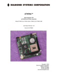
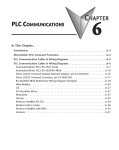
Functional Block Diagram
Figure 1 shows the Pegasus functional blocks.
Figure 1: Pegasus Functional Block Diagram
Diamond Systems Corporation
Pegasus User Manual
Page 9
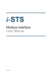
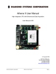
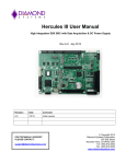
Board Diagram
Figure 2 and Figure 3 show the Pegasus board layout, including connectors, jumper blocks and mounting holes.
Figure 2: Pegasus Board Layout (top)
Figure 3: Pegasus Board Layout (bottom)
Diamond Systems Corporation
Pegasus User Manual
Page 10
Connector Summary
The following table lists the Pegasus board connectors.
Connector
PC104P1
KBMS1
VGA1
IDE1
MISC1
LVDS1
J2
LAN1
USB1
USB2
PWR1
PWR2
IO_P1
EBAT1
INV1
Description
PC/104 ISA Bus
PS/2 Mouse and Keyboard
VGA
IDE Bus
Miscellaneous
LCD Panel - LVDS Interface
COM1/2 Serial Port I/O
Ethernet
USB 2.0 Ports (0/1)
USB 2.0 Ports (2/3)
Main Input Power
Panel Power Input
I/O Power
External Battery
LCD Backlight
Jumper Summary
The following table lists the Pegasus board jumpers block.
Jumper
JRS1
JTM1
J1
JVCC01
JINV1
JBAT1
Diamond Systems Corporation
Description
COM2 RS-232/422/485 select
COM2 RS-232/RS-485 configuration
LCD configuration
LVDS panel voltage configuration
LCD backlight voltage configuration
CMOS setup
Pegasus User Manual
Page 11
Connectors
This section describes the on-board Pegasus connectors.
Note: Pins marked as “key” are cut away or removed, unless otherwise indicated.
PC/104 ISA Bus (PC104P1)
These two connectors carry the ISA bus signals. The following diagram shows the PC/104 pin layout.
IOCHCHKSD7
SD6
SD5
SD4
SD3
SD2
SD1
SD0
IOCHRDY
AEN
SA19
SA18
SA17
SA16
SA15
SA14
SA13
SA12
SA11
SA10
SA9
SA8
SA7
SA6
SA5
SA4
SA3
SA2
SA1
SA0
Ground
A1
A2
A3
A4
A5
A6
A7
A8
A9
A10
A11
A12
A13
A14
A15
A16
A17
A18
A19
A20
A21
A22
A23
A24
A25
A26
A27
A28
A29
A30
A31
A32
Diamond Systems Corporation
B1
B2
B3
B4
B5
B6
B7
B8
B9
B10
B11
B12
B13
B14
B15
B16
B17
B18
B19
B20
B21
B22
B23
B24
B25
B26
B27
B28
B29
B30
B31
B32
Ground
RESETDRV
+5V
IRQ9
-5V
DRQ2
-12V
ENDXFR+12V
Key
SMEMWSMEMRIOWIORDACK3DRQ3
DACK1DRQ1
REFRESHSYSCLK
IRQ7
IRQ6
IRQ5
IRQ4
IRQ3
DACK2TC
BALE
+5V
OSC
Ground
Ground
Pegasus User Manual
Ground
SBHELA23
LA22
LA21
LA20
LA19
LA18
LA17
MEMRMEMWSD8
SD9
SD10
SD11
SD12
SD13
SD14
SD15
Key
C0
C1
C2
C3
C4
C5
C6
C7
C8
C9
C10
C11
C12
C13
C14
C15
C16
C17
C18
C19
D0
D1
D2
D3
D4
D5
D6
D7
D8
D9
D10
D11
D12
D13
D14
D15
D16
D17
D18
D19
Ground
MEMCS16-IOCS16IRQ10
IRQ11
IRQ12
IRQ15
IRQ14
DACK0DRQ0
DACK5DRQ5
DACK6DRQ6
DACK7DRQ7
+5
MASTERGround
Ground
Page 12
PS/2 Mouse and Keyboard (KBMS1)
Connector KBMS1 provides the standard PS/2 keyboard and mouse signals.
+5V
1
2
+5V
KB Data
3
4
MS Data
KB Clock
5
6
MS Clock
Ground
7
8
Key
NC
9
10
Ground
Signal
+5V
KB Data
KB Clock
MS Data
MS Clock
Ground
Definition
keyboard PS/2 pin 4
keyboard PS/2 pin 1
keyboard PS/2 pin 5
mouse PS/2 pin 1
mouse PS/2 pin 5
PS/2 pin 3
VGA (VGA1)
Connector VGA1 is used to connect a VGA monitor.
Note: While the DDC serial detection pins are present, a 5V power supply is not provided, and the
legacy “Monitor ID” pins are also not used.
Signal
Red
Green
Blue
DDC Clock/Data
HSYNC
VSYNC
Ground
Red
1
2
Ground
Green
3
4
Key
Blue
5
6
Ground
HSYNC
7
8
DDC Data
VSYNC
9
10
DDC Clock
Definition
RED signal (positive, 0.7Vpp into 75 Ohm load)
GREEN signal (positive, 0.7Vpp into 75 Ohm load)
BLUE signal (positive, 0.7Vpp into 75 Ohm load)
Digital serial I/O signals used for monitor detection (DDC1 specification)
Horizontal sync
Vertical sync
Ground return
IDE Bus (IDE1)
The IDE connector, IDE1, is used to connect two IDE drives, including hard disks, CD-ROMs and Flashdisk
modules.
Diamond Systems Corporation
Pegasus User Manual
Page 13
This connector mates with Diamond Systems cable part number 6981004.
Reset -
1
2
Ground
D7
3
4
D8
D6
5
6
D9
D5
7
8
D10
D4
9
10
D11
D3
11
12
D12
D2
13
14
D13
D1
15
16
D14
D0
17
18
D15
Ground
19
20
Key
DRQ
21
22
Ground
IDEIOW-
23
24
Ground
IDEIOR-
25
26
Ground
IORDY
27
28
Ground
DACK-
29
30
Ground
IRQ14
31
32
Pulled low for 16-bit operation
A1
33
34
NC
A0
35
36
A2
CS0-
37
38
CS1-
LED-
39
40
Ground
+5v
41
42
+5v
Ground
43
44
NC
Signal
Reset D0-D15
Ground
DRQ
DACKIDEIOWIDEIORIORDY
IRQ14
A0-A2
CS0CS1LED+5V
Diamond Systems Corporation
Definition
Reset
16-bit data
Ground
DDRQ
DDACK
I/O write
I/O read
IOC HRDY
IRQ
Address 0-2
Chip select 1P
Chip select 3P
Activity indication
+5VDC
Pegasus User Manual
Page 14
Miscellaneous (MISC1)
Connector MISC1 provides access to common auxiliary signals.
Ground
1
2
Reset-
IDE LED
3
4
+5V
Power LED
5
6
+5V
Speaker
7
8
+5V
LCD Backlight Control
9
10
key
Signal
Definition
IDE LED
IDE drive activity indication LED.
Power LED
Power enabled LED.
LCD Backlight Control User-provided brightness control for the LCD backlight. See the
description for connector INV1.
0V = max.
5V = min.
Speaker
Speaker connection; referenced to +5V.
+5V
+5VDC power.
ResetConnect this pin to ground to cause a reset condition.
Ground
Ground
Diamond Systems Corporation
Pegasus User Manual
Page 15
LCD Panel - LVDS Interface (LVDS1)
Connector LVDS1 provides access to the internal LVDS LCD display drivers.
Note: The LCD also requires the backlight (connector INV1) to be connected to function correctly.
Signal
SD
FRC
PClk+
PClkVDD Sel
SigGround
PwrGround
Diamond Systems Corporation
1
NC
2
NC
3
SD
4
FRC
5
SigGround
6
PClk+
7
PClk-
8
SigGround
9
D2+
10
D2-
11
SigGround
12
D1+
13
D1-
14
SigGround
15
D0+
16
D0-
17
PwrGround
18
PwrGround
19
VDD Sel
20
VDD Sel
Definition
Scan Direction; controlled by jumper J1 (default low).
High
= Reverse scan.
Low/open = Normal scan.
Frame Rate Control; controlled by jumper J1 (default low).
High
= On.
Low/open = Off.
Pixel clock +.
Pixel clock -.
VCC 3.3v or 5V (Jumper JVLCD1 configured).
Signal ground.
Power ground.
Pegasus User Manual
Page 16
Serial Port I/O (COM1/2)
Connector COM1/2 provides access to the two serial ports of the AMD Geode CPU. PORT1 is RS-232, only.
PORT2 is independently, jumper-configurable for either RS-232, RS-485 or RS-422 protocol. Jumpers JRS1 and
JTM1 are used to select the protocol.
Connector pins are dedicated to a port, as shown in the following table.
Port No.
PORT1
PORT2
Pin Assignment
Pins 1 - 10
Pins 11 - 20
The following tables list the signals and associated DE-9 pin numbers for each of the protocols; pin assignment
differs, depending on the protocol selected.
RS-232 Pin Assignments
COM1:
COM2:
Signal
DCDn
DSRn
RXDn
RTSn
TXDn
CTSn
DTRn
RIn
Ground
Diamond Systems Corporation
DCD1
1
2
DSR1
RXD1
3
4
RTS1
TXD1
5
6
CTS1
DTR1
7
8
RI1
Ground
9
10
Ground
DCD2
11
12
DSR2
RXD2
13
14
RTS2
TXD2
15
16
CTS2
DTR2
17
18
RI2
Ground
19
20
Ground
Definition
Data Carrier Detect
Data Set Ready
Receive Data
Request to Send
Transmit Data
Clear to Send
Data Terminal Ready
Ring Indicator
Ground
Pegasus User Manual
DE-9 Pin
pin 1
pin 6
pin 2
pin 7
pin 3
pin 8
pin 4
pin 9
-
Direction
Input
Input
Input
Output
Output
Input
Output
Input
-
Page 17
RS-485 Pin Assignment
Only COM1/2 connector pins 11 through 20, PORT2, is used for RS-485.
COM2:
Signal
TXD/RXD+
TXD/RXDGround
NC
NC
11
12
NC
TXD/RXD+
13
14
TXD/RXD-
NC
15
16
NC
NC
17
18
NC
Ground
19
20
Ground
Definition
Differential Transceiver Data (HIGH)
Differential Transceiver Data (LOW)
Ground
(not connected)
DE-9 Pin
pin 2
pin 7
-
Direction
bi-directional
bi-directional
-
DE-9 Pin
-
Direction
Output
Input
-
RS-422 Pin Assignment
Only COM1/2 connector pins 11 through 20, PORT2, is used for RS-422.
COM2:
Signal
TXD+/TXDRXD+/RXDGround
NC
Diamond Systems Corporation
NC
11
12
NC
TXD+
13
14
TXD-
RXD+
15
16
RXD-
NC
17
18
NC
Ground
19
20
Ground
Definition
Differential transmit data
Differential receive data
Ground
(not connected)
Pegasus User Manual
Page 18
Ethernet (LAN1)
The 10/100 Base-T, full-duplex Ethernet interface is provided by connector LAN1.
Signal
TX+/TXRX+/RXLink LED
Act+/Act-
TX+
1
2
TX-
NC
3
4
RX-
RX+
5
6
Link LED-
Link LED+
7
8
Act+
Key
9
10
Act-
Definition
Transmit data.
Receive data.
Link activity indication; referenced to ground.
Activity LED indicator.
USB 2.0 Ports (USB1, USB2)
The board features four USB 2.0 ports. Connector USB1 interfaces to USB port 0/1 and connector USB2 interfaces
to USB ports 2/3. USB 2.0 provides a 480Mbps maximum data transfer rate.
USB1
Ground
1
2
USB0 VCC
USB0 Data+
3
4
USB0 Data-
Key
5
6
Ground
Ground
7
8
USB1 VCC
USB1 Data+
9
10
USB1 Data-
Ground
1
2
USB2 VCC
USB2 Data+
3
4
USB2 Data-
USB2
Key
5
6
Ground
Ground
7
8
USB3 VCC
USB3 Data+
9
10
USB3 Data-
Signal
USB0-3 VCC
USB0-3 Data+
USB0-3 DataGround
Diamond Systems Corporation
Definition
+5V power for USB ports 0-3
Data + for USB ports 0-3
Data - for USB ports 0-3
Ground; tied to system ground.
Pegasus User Manual
Page 19
Main Input Power (PWR1)
Input power may be supplied using either PWR1, the I/O power connector (IO_P1), an external supply, or directly
through the PC/104 bus power pins, if a PC/104 power supply is used with the SBC.
The board only requires +5VDC input power to operate. All other required voltages are generated on board.
However, the PC/104 bus may be used to supply ±5V and ±12V, if needed.
Multiple +5V and ground pins are provided for extra current carrying capacity, if needed. Each pin is rated at 3A
max. For applications requiring less than 3A, the first four pins may be connected to a standard 4-pin miniature PC
power connector, or the alternate power I/O connector may be used. For a larger PC/104 stack the total power
requirements should be calculated to determine whether additional wires are necessary.
Signal
+5VDC
+12VDC
-12VDC
Ground
Ground
1
2
+5VDC
Ground
3
4
+12VDC
Ground
5
6
-12VDC
Key
7
8
+5VDC
Ground
9
10
+5VDC
Definition
+5V input. Only +5VDC power is required for board operation.
+12V input.
-12V input.
Ground
Panel Power Input (PWR2)
Connector PWR2 provides power to the board when connected to the I/O panel board. All signals are routed to their
corresponding pins on the PC/104 connector.
Signal
+5V
+12V
Ground
Diamond Systems Corporation
+5V
1
2
+5V
+5V
3
4
Ground
Ground
5
6
Ground
+12V
7
8
+12V
Definition
+5V input. Only +5VDC power is required for board operation.
+12V input. Provided as a pass-through to the PC/104 bus connector.
Ground
Pegasus User Manual
Page 20
I/O Power (IO_P1)
Connector IO_P1 provides an alternate connector for either input power to the system or output power for use with
external drives.
This connector mates with Diamond Systems cable part number 6981006, which provides a standard full-size power
connector for a hard drive or CD-ROM drive and a standard miniature power connector for a floppy drive.
Signal
+5V I/O
+12V I/O
Ground
1
+5V I/O
2
Ground
3
Ground
4
+12V I/O
Definition
This is provided by the on-board power supply, derived from the input power.
It is switched off when the board is powered down.
This is provided by the 12V input pin on the main power connector. It is
switched off when the board is powered down.
These are 0V ground references for the power output voltage rails.
External Battery (EBAT1)
Connector EBAT1 is used to connect an external battery to augment or replace the on-board backup battery.
In addition to the external battery, the on-board battery is another possible sources for maintaining the Real-Time
Clock and the CMOS BIOS settings for various system configurations. The battery that has the highest voltage will
see the majority of the current draw, which is minimal.
Note: There must be a battery voltage input for the default power-up mode.
1
Ground
2
Battery input (+)
Signal
Definition
Battery Input Battery input voltage. The battery voltage for this input should be 3V. The
current draw averages under 5µA at 3V.
Ground
Battery ground.
Diamond Systems Corporation
Pegasus User Manual
Page 21
LCD Backlight (INV1)
Connector INV1 provides the backlight power and control for the optional LCD panel. See the description for
connector LVDS1 for detailed information on the LCD data interface.
The control signal is used to allow the system to power-down the backlight when the system enables monitor-powerdown during power management control.
Note: If needed, 12V must be provided, either on one of the input power connectors or on the 12V
pin (B9) of the PC/104 connector, for the LCD backlight to operate. The board does not generate the
voltage, internally.
Signal
INV Sel
Dispen
Brightness
Ground
Diamond Systems Corporation
1
INV Sel
2
INVSel
3
Ground
4
Ground
5
Dispen
6
Brightness
Definition
+5V or +12V power supply for LCD Backlight
assembly, jumper J18 selectable.
The +12V supply is removed when the system is
powered down.
Enable (GPIO output)
0 = disable.
open circuit = enable.
GP35
0 = disable.
1 = enable. (Default)
Brightness, 0-5VDC.
0V = max.
5V = min.
GP36
0 = max. (Default)
1 = min.
Ground for LCD Backlight assembly.
Pegasus User Manual
Page 22
Board Configuration Jumper
The following jumpers provide the board configuration options:
Jumper Block
JRS1
JTM1
J1
JVLCD1
JINV1
JBAT1
Configuration Functions
COM2 RS-232/422/485 select.
COM2RS-232/RS-485 configuration.
LCD configuration.
LVDS panel voltage configuration.
LCD backlight voltage configuration.
CMOS setup.
COM2 RS-232/422/485 Select (JRS1)
Use jumper JRS1 to select the COM2 RS-232/RS-422/RS-485 protocol option and RS-422/RS-485 termination, as
shown in Figure 4.
Note: The JRS1 and JMT1 jumpers share the same jumper block.
Figure 4: Jumper Block JRS1 Settings
Diamond Systems Corporation
Pegasus User Manual
Page 23
COM2 RS-232/RS-485 Configuration (JTM1)
Use jumper block JTM1 to configure the COM2 port in RS-422/485 modes, as shown in Figure 5. The default
setting is with no jumpers installed.
Note: The JMT1 and JRS1 jumpers share the same jumper block.
Figure 5: Jumper Block JTM1 Settings
Diamond Systems Corporation
Pegasus User Manual
Page 24
LCD Configuration (J1)
Jumper block J1 configures the LCD frame rate and scan direction.
Figure 6: LCD Configuration Jumper Settings
LVDS Panel Voltage Configuration (JVLCD1)
Jumper block JVLCD1 sets the LCD input voltage to +5V or +3.3V.
Note: The JVLCD1 and JINV1 jumpers share the same jumper block.
Figure 7: LVDS Panel Voltage Configuration
LCD Backlight Voltage Configuration (JINV1)
Jumper block JINV1 sets the LCD backlight voltage to +5V or +12V.
Note: The JINV1 and JVLCD1 jumpers share the same jumper block.
Figure 8: LCD Backlight Voltage Configuration
CMOS Setup (JBAT1)
The three-pin jumper block, JBAT1 shown in Figure 9, is used to maintain or clear the CMOS settings. Jumpering
pins 1-2, the SBC powers up with the default BIOS settings and battery power is maintained to CMOS.
Diamond Systems Corporation
Pegasus User Manual
Page 25
Figure 9: Jumper Block JBAT1 Settings
Follow these steps to clear the CMOS RAM.
1.
2.
3.
4.
5.
Power-down the SBC.
Remove the JBAT1 jumper and move it to the clear CMOS position, jumpering pins 2-3.
Wait ten seconds.
Insert the jumper on pins 1-2.
Power-up the SBC.
Note: Before erasing CMOS RAM, record any custom BIOS settings.
Diamond Systems Corporation
Pegasus User Manual
Page 26
Installation and Configuration
This section describes the steps needed to get your Pegasus board up and running, and assumes that you have also
purchased the Pegasus Development Kit. The development kit includes all cables described in the previous section,
a power supply, USB floppy drive, mounting hardware, IDE flashdisk and the flashdisk programmer board.
Hardware Installation
General Setup
Follow these steps to power on and verify the functionality of the Pegasus SBC. This process assumes you have a
Pegasus SBC and cable kit.
6. Connect a VGA monitor to the SBC. Attach VGA cable number 6981084 to the VGA connector on the SBC
and connect your monitor VGA c able to the DB9 socket.
7. Connect a keyboard and mouse to the SBC. Attach the PS/2 keyboard/mouse cable, number 6981162, to the PS/
2 connector on the SBC and connect your keyboard and mouse devices to the connectors on the other end of the
cable.
8. (Optional for USB keyboard/mouse) If you are using a USB keyboard and mouse, attach USB cable number
6981171 to the USB0-2 connector on the SBC and connect your keyboard and mouse devices to the connectors
on the other end of the cable.
9. Connect an external IDE hard drive or CD device to the SBC. Attach the IDE ribbon cable, number 6981004, to
the IDE/FlashDisk connector on the SBC and connect your IDE device to the connector on the other end of the
cable.
Note: You must provide an external source of power for your IDE device.
10. (Optional for USB storage device) If you are using a USB storage device, attach USB cable number 6981171 to
the USB0-1 (USB2-3, if using a USB keyboard and mouse) connector on the SBC and connet your external
storage device to the USB0 (USB2-3, if using a USB keyboard and mouse) connector on the other end of the
cable.
11. Connect the SBC power. Attach power cable number 6981175 to the Power In connector on the SBC. Ensure
that your +5V power source is off. Connect your +5V power source to the other end of the cable.
12. Turn on the power source.
The Pegasus BIOS screen should appear, followed by the SBC beginning booting from the external storage device.
When you plug PC/104 boards onto Pegasus, the BIOS may or may not recognize the new board. If the new board
is not recognized, you may need to configure the new hardware in the BIOS before being able to use it. You can
configure the system's IRQ/DMA resources from the BIOS's PnP/PCI Configuration screen. The following table
shows the USB2-3, if using a USB keyboard and mouse IRQ levels.
Diamond Systems Corporation
Pegasus User Manual
Page 27
IRQ Level
Funcxtion
IRQ 01
PC/AT Enhances PS/2 Keyboard
IRQ 03
Communications Port
IRQ 04
Communications Port
IRQ 05
Standard Enhanced PCI-to-USB Host Controller
IRQ 05
Standard Open HCD USB Host Controller
IRQ 06
Standard Floppy Disk Controller
IRQ 10
Advanced Micro Devices Win 2K/Win Graphics Driver
IRQ 10
Geode LX AES Crypto Driver
IRQ 11
Realtek RTL8139/810x Family Fast Ethernet NIC
IRQ 12
Microsoft PS/2 Mouse
IRQ 14
Primary IDE Channel
IDE Configuration
The on-board PCI IDE connector supports two IDE devices:
•
•
A primary master.
A primary slave.
The supported IDE devices include the on-board FlashDisk, a CompactFlash disk, a FlashDisk plug-in module on
the IDE connector, or external IDE devices. You can configure the system's IDE devices from the BIOS Standard
CMOS Features screen. Many devices have on-board jumpers for configuration as a master or slave. Consult the
device User Manual for details.
The following tables show the possible IDE device combinations for the two Pegasus models.
Model PGS800-256-2G
Master
Slave
Device on IDE Connector
2GB on-board FlashDisk
CompactFlash Disk
2GB on-board FlashDisk
Note: The 2GB on-board FlashDisk on Pegasus model PGS800-256-2G is fixed as the primary slave
device and defaults to drive C:, if no other bootable device is found. If a bootable device is found as
the primary master, the on-board FlashDisk is assigned drive D:. This model does not allow for a
device on the IDE connector and a CompactFlash disk to co-exist.
Model PGS800-256
Master
Slave
Device on IDE Connector
Device on IDE Connector
CompactFlash Disk
Device on IDE Connector
Diamond Systems Corporation
Pegasus User Manual
Page 28
DOS Operating System Installation
User the following sequence to install DOS operating systems: MS-DOS, FreeDOS and ROM-DOS.
1. Enable the following in BIOS:
•
•
Floppy Drive detection.
Legacy USB support.
2. Change the BIOS boot sequence so the system boots through the USB floppy drive.
3. Insert the DOS installation floppy disk into the USB floppy drive and start/restart the system.
4. Install any drivers needed.
Notes:
1. For DOS Ethernet, set Operating System to other in the BIOS.
2. DOS Sound emulation is currently not functional.
CompactFlash Issues under DOS
CompactFlash is incompatible with some utilities, under some versions of DOS.
•
CompactFlash with ROM-DOS
The ROM-DOS FDISK utility does not work with CompactFlash drives. The ROM-DOS FORMAT and SYS
do work, however. If CompactFlash already has a DOS partition, the ROM-DOS utilities can be used to
FORMAT the CompactFlash and install operating system files on CompactFlash.
•
CompactFlash with FreeDOS
The FreeDOS FDISK or FORMAT utility do not work with CompactFlash. However, the FreeDOS SYS utility
is functional with CompactFlash.
•
CompactFlash with MS-DOS
The MS-DOS FDISK, FORMAT, and SYS utilities are not functional when used with CompactFlash. The MSDOS operating system files cannot be installed on CompactFlash flash.
Diamond Systems Corporation
Pegasus User Manual
Page 29
Boot Procedures
Booting into MS-DOS, FreeDOS or ROM-DOS
This section describes how to boot into a DOS-based operating system using a bootable floppy disk.
1. Plug the USB floppy drive into one of the USB terminals of cable 6981171.
2. Insert your DOS-based boot disk into the USB floppy drive.
3. Connect the power supply to the wall (to provide power to Pegasus).
4. At this point the Pegasus will boot and you should see the BIOS power-on self test. Press F2 to enter BIOS
configuration.
5. Under the “Advanced” menu, scroll to “Legacy USB Support” and enable it. (Without enabling this option, the
BIOS will not boot from a disk in the USB floppy drive).
6. Reboot the system to boot from your floppy disk.
Booting into Linux
This section describes how to setup the Pegasus board in preparation for a Linux install, from an installation CDROM onto a laptop IDE hard drive.
1. Connect the IDE FashDisk programmer board to IDE1.
2. Connect a CD-ROM drive jumpered for the slave position to the IDE FlashDisk programmer board through the
40-pin cable.
3. Connect the CD-ROM drive using cable 6981006 attached to IO_P1. Be sure that an external 12VDC source is
being suppled to the CD-ROM.
4. Connect a laptop hardvdrive jumpered for master position to the second slot of the 44-pin cable.
5. Boot the Pegasus by plugging the power supply into the wall.
6. Press F2 at the power-on self test to go to the BIOS configuration screen.
7. Go to the “Boot” menu and confirm that the CD-ROM drive is first boot device.
8. Insert the boot CD for your operating system into the CD-ROM drive.
9. Save the BIOS settings and reboot.
10. You should now be able to install your OS.
Diamond Systems Corporation
Pegasus User Manual
Page 30
BIOS Setup
Pegasus uses a BIOS from Phoenix Technologies modified to support the custom features of the Pegasus board.
(See the detailed BIOS settings in Appendix A – BIOS CMOS Option Listing)
To change the BIOS settings, repeatedly press the delete key <Del> during system startup power-on self-test
(POST).
Diamond Systems Corporation
Pegasus User Manual
Page 31
System I/O Description
Ethernet
The Ethernet port is built into the AMD Geode chipset and is connected to the system via the board’s internal PCI
bus.
A DOS utility program is provided for testing the chip and accessing the configuration EEPROM. Each board is
factory-configured for a unique MAC address using this program. To run the program, boot the computer to DOS
because the program will not run properly in a DOS window. In normal operation this program is not required.
Additional software support includes a packet driver with software to allow a full TCP/IP implementation.
Serial Ports
Pegasus contains two serial ports. Each port is capable of transmitting at speeds up to 115.2Kbaud. Ports COM1
and COM2 are built into the AMD Geode chipset, which are standard 16550 UARTs with 16-byte FIFOs.
The serial ports use the following default system resources.
Port
COM1
COM2
I/O Address Range
3F8-3FF
2F8-2FF
IRQ
4
3
The COM1 and COM2 settings may be changed in the system BIOS. Select the TBD menu to modify the base
address and interrupt level.
PS/2 Ports
Pegasus supports two PS/2 ports.
•
•
Keyboard
Mouse
Support for these ports is independent of, and in addition to, mouse and keyboard support using the USB ports.
USB Ports
Four USB 2.0 ports are intended primarily for the following devices, although, any USB-standard device should
function.
•
•
•
•
Keyboard
Mouse
USB Floppy Drive (This is required for Crisis Recovery of boot ROM.)
USB flash disk
The BIOS supports the USB keyboard during BIOS initialization screens and legacy emulation for DOS-based
applications.
The USB ports can be used for keyboard and mouse at the same time that the PS/2 keyboard and mouse are
connected.
Diamond Systems Corporation
Pegasus User Manual
Page 32
System Resources
The table below lists the default system resources utilized by the circuits on Pegasus.
Device
Serial Port COM1
Serial Port COM2
IDE Controller A
Watchdog Timer/Serial
Port/FPGA Control
Ethernet
USB
Video
Address
I/O 0x3F8 – 0x3FF
I/O 0x2F8 – 0x2FF
I/O 0x1F0 – 0x1F7
I/O 0x25C-0x25F
ISA IRQ
4
3
14
–
ISA DMA
–
–
–
–
OS-dependent
OS-dependent
OS-dependent
OS-dependent
OS-dependent
OS-dependent
–
–
–
Most of these resources are configurable and, in many cases, the Operating System alters these settings. The main
devices that are subject to this dynamic configuration are on-board Ethernet, sound, video, USB, and any PC/104Plus cards that are in the system. These settings may also vary depending on what other devices are present in the
system. For example, adding a PC/104-Plus card may change the on-board Ethernet resources.
The serial port settings for COM2 are jumper-selectable, using jumper block JRS1.
Console Redirection to a Serial Port
In many applications without a local display and keyboard, it may be necessary to obtain keyboard and monitor
access to the CPU for configuration, file transfer, or other operations. Pegasus supports this operation by enabling
keyboard input and character output onto a serial port, referred to as console redirection. A serial port on another
PC can be connected to the serial port on Pegasus with a null modem cable, and a terminal emulation program, such
as HyperTerminal, can be used to establish the connection. The terminal program must be capable of transmitting
special characters including F2 (some programs or configurations trap special characters).
The default Pegasus BIOS setting disables console redirection.
There are three possible configurations for console redirection:
•
•
•
POST-only (default)
Always On
Disabled
To modify the console redirection settings,
1. Enter the BIOS
2. Select the Advanced menu
3. Select Console Redirection.
4. In Com Port Address, select Disabled to disable the function, On-board COM A for COM1, or On-board COM B
for COM2 (default).
If you select Disabled, you will not be able to enter BIOS again during power-up through the serial port.
To reenter BIOS when console redirection is disabled, you must either install a PC/104 video board and use a
keyboard and terminal or erase the CMOS RAM, which will return the BIOS to its default settings. CMOS RAM
may be erased by removing the jumper on the JBAT1 jumper block.
Diamond Systems Corporation
Pegasus User Manual
Page 33
Note: Before erasing CMOS RAM, write down any custom BIOS settings you have made.
If you erase the CMOS RAM, the next time the CPU powers up COM2 returns to the default settings of
115.2Kbaud, N, 8, 1 and operates only during POST.
If you selected COMA or COMB, continue with the configuration, as follows.
1. For Console Type, select PC ANSI.
2. You can modify the baud rate and flow control here if desired.
3. At the bottom, for Continue C.R. after POST, select Off (default) to turn off after POST or select On to remain
on always.
4. Exit the BIOS and save your settings.
Watchdog Timer
Pegasus contains a watchdog timer circuit consisting of two programmable timers, WD1 and WD2, cascaded
together. The input to the circuit is WDI and the output is WDO. WDI may be triggered in hardware or in software.
A special “early” version of WDO may be output on the WDO pin. When this signal is connected to WDI, the
watchdog circuit is re-triggered automatically.
The duration of each timer is user-programmable. When WD1 is triggered, it begins to count down. When it
reaches zero, it triggers WD2, sets WDO high, and may also generate a user-selectable combination of the
following events.
•
•
System Management interrupt (SMI)
Hardware reset
WD2 then begins to count down. When the WD2 counter reaches zero, it unconditionally causes a hardware reset.
The WD2 timer gives external circuits time to respond to the WDO event before the hardware reset occurs.
The watchdog timer circuit is programmed via I/O registers located on Page 0: Base +28-31.
Flash Memory
Pegasus contains a 512KB, 16-bit wide flash memory chip for storage of BIOS and other system configuration data.
Backup Battery
Pegasus contains an integrated RTC/CMOS RAM backup battery. This battery has a capacity of 120mAH and will
last over five years in power-off state.
The on-board battery is activated for the first time during initial factory configuration and test. Storage temperature
of the board can affect the total battery life. Storage at 23ºC is recommended.
Diamond Systems Corporation
Pegasus User Manual
Page 34
System Reset
Pegasus contains a chip to control system reset operation. Reset occurs under the following conditions.
•
•
•
User causes reset with a ground contact on the Reset input.
Input voltage drops below 4.75V.
Over-current condition on output power line .
The ISA Reset signal is an active high pulse with a 200ms duration. The PCI Reset is active low, with a typical
pulse width duration of 200 msec.
On-Board Video
Pegasus provides VGA CRT and LVDS flat panel video using the built-in AMD Geode chipset.
Diamond Systems Corporation
Pegasus User Manual
Page 35
Watchdog Timer Programming
Pegasus contains a watchdog timer circuit consisting of one programmable timer. The input to the circuit is WDI
and the output is WDO, which appear on connector J6. WDI may be triggered in hardware or in software. A special
“early” version of WDO may be output on the WDO pin. When this signal is connected to WDI, the watchdog
circuit is retriggered automatically.
The watchdog timer duration is user-programmable. When WDT is triggered, it begins to count down. Upon
reaching zero, it generates a user-selectable combination of the following events.
•
•
System management interrupt
Hardware reset
The watchdog timer circuit is programmed using I/O registers located at address 0x25C. Detailed programming
information is described, below.
Watchdog Timer Register Details
The registers in the following table are used to program the watchdog timer.
I/O Address
0x25C
0x25D
0x25E
0x25F
Write Function
WDT trigger
WDT, counter
Watchdog control
Chip select enable/disable
Read Function
None, write-only
None, write-only
Readback
Readback the last bits written
In the tables, below, a blank bit (-) indicates the bit is unused. A blank bit in the read registers reads back as 0 or 1,
unknown state.
I/O Address: 0x25C (Write)
Bit:
Name:
WDTRIG
7
6
-
5
4
WDTRIG
3
2
1
0
1
0
-
Writing a 1 triggers an immediate software reload of the watchdog timer.
I/O Address: 0x25D (Write)
Bit:
Name:
WDT0-3
7
WDT3
6
WDT2
5
WDT1
4
WDT0
3
2
-
Writing to bits WDT0-3 loads the watchdog timer with the 4-bit counter value. Use this register to set
the countdown period. Each tick is 145ms, so the period range is 145ms (1) to 2.175ms (15).
Diamond Systems Corporation
Pegasus User Manual
Page 36
I/O Address: 0x25E (Read/Write)
Bit:
Name:
7
WDIEN
6
WDOEN
5
WDSMI
4
WDEDGE
3
2
1
0
1
0
-
WDIEN
0 = Disable edges on the WDI pin, retriggering watchdog timer.
1 = Enable egdes on the WDI pin retriggering watchdog timer.
WDOEN 0 = Disable edge on WDO pin when watchdog timer reaches 1.
1 = Enable edge on WDO pin when watchdog timer reaches 1.
WDSMI
0 = Disable system management interrupt signal when watchdog timer reaches 0.
1 = Enable system management interrupt signal when watchdog timer reaches 0.
WDEDGE 0 = Falling edge on WDI retriggers watchdog timer, when WDIEN = 1.
1 = Rising edge on WDI retriggers watchdog timer, when WDIEN = 1.
I/O Address: 0x25F (Read/Write)
Bit:
Name:
7
COM4EN
COM4EN
COM3EN
FPGAEN
WDEN
6
COM3EN
5
FPGAEN
4
WDEN
3
2
-
COM4 chip select enable.
1 = Enable COM4-CS#.
0 = Disable COM4-CS#.
COM3 chip select enable.
1 = Enable COM3-CS#.
0 = Disable COM3-CS#.
FPGA chip select enable.
1 = Enable FPGA-CS#.
0 = Disable FPGA-CS#.
Watchdog enable.
1 = Watchdog timer counter enable.
0 = Watchdog timer counter disable, WDO disable, WDI disable, CPURST# disable, EXTSMI#
disable.
The CPLD initializes all values to zero on power up, and the BIOS enables each resource based on BIOS settings.
Example: Watchdog Timer With Software Trigger
A software trigger relies on a thread of execution to constantly trigger watchdog timer A. If the thread is ever
halted, timer A decrements to zero and starts timer B. Once timer B decrements to 0, the board resets.
In this example we set the watchdog timer to a countdown period of four seconds. Longer timeout periods are
typically be used for a software-based watchdog timer, to accommodate varying software latencies, such as interrupt
latencies and thread pre-emption, that may delay the watchdog trigger code.
Setting up the watchdog timer:
outp(base + 0, 0x00);
Diamond Systems Corporation
//set page 0
Pegasus User Manual
Page 37
outp(base
outp(base
outp(base
outp(base
+
+
+
+
28,
29,
30,
31,
40000 & 0xFF); //set LSB of WD timer A (4 seconds)
(40000 >> 8) & 0xFF);
//set MSB of WD timer A
0xFF);
//set WD timer B to 0.0255 seconds
0x28);
//set WDEN=1, WDRST=1 (enable WD timer, reset)
With the timer setup and active, run the watchdog timer trigger in a continuous thread of code.
while (1)
{
outp(base + 31, 0x80);
sleep(1000);
}
//trigger watchdog timer
//sleep one second
If this thread is interrupted for any reason, the board resets four seconds after the last watchdog timer trigger.
Example: Watchdog Timer With Hardware Trigger
A hardware trigger relies on an external pulse to constantly trigger watchdog timer A. If the external stream of
pulses ever halts, timer A decrements to zero and starts timer B. Once timer B decrements to 0, the board resets.
In this example, we will make use of the T-1 feature of timer A to automatically reset itself unless a physical
connection is broken. The physical connection must be made between WDO and WDI on the data acquisition
header, J6.
Since software is not involved in maintaining the timer, we can set the reset period to a much smaller value. In this
example, the reset pulse travels across the physical connection every 10 milliseconds.
outp(base
outp(base
outp(base
outp(base
outp(base
+
+
+
+
+
0, 0x00);
//set page 0
28, 100 & 0xFF);
//set LSB of WD timer A (10 milliseconds)
29, 100 >> 8) & 0xFF);
//set MSB of WD timer A
30, 0xFF);
//set WD timer B to 0.0255 seconds
31, 0x2D);
//set WDEN=1, WDRST=1, WDT-1=1, WDIEN=1
When timer A reaches 1, a rising edge flows from WDO to WDI, resetting the timer back to 100 and lowering
WDO.
When the connection from WDO to WDI is broken, the rising edge never reaches WDI and system resets.
Diamond Systems Corporation
Pegasus User Manual
Page 38
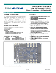
FlashDisk Module
Pegasus is designed to accommodate an optional solid-state FlashDisk module. Diamond Systems Offers FlashDisk
modules that contain 128MB to 4GB of solid-state non-volatile memory that operates like an IDE drive without
requiring additional driver software support.
Model
FD-128-XT
FD-256-XT
FD-512-XT
FD-1G-XT
FD-2G-XT
FD-4G-XT
Capacity
128MB
256MB
512MB
1GB
2GB
4GB
Figure 10: FlashDisk Module
Installing the FlashDisk Module
The FlashDisk module installs directly on the IDE connector, IDE1, and is held down with a spacer and one screw
onto a mounting hole on the board.
The FlashDisk module contains a jumper for master/slave configuration. For master mode, install the jumper over
pins 1 and 2. For slave mode, install the jumper over pins 2 and 3.
Configuration
To configure the SBC to work with the FlashDisk module, enter the BIOS by pressing F2 during startup. Select the
Main menu, and then select IDE Primary Master. Enter the settings shown in the following table.
Diamond Systems Corporation
Pegasus User Manual
Page 39
Setting
Type
Cylinders
Heads
Sectors
Multi Sector Transfer
LBA Mode Control
32 Bit I/O
Transfer Mode
Ultra DMA Mode
Value
User
977 for 128MB flashdisk
8 for 128MB flashdisk
32 for 128MB flashdisk
Disable
Enable
Disable
Fast PIO 1
Disable
Exit the BIOS and save the change. The system will now boot and recognize the FlashDisk module as drive C:.
Using the FlashDisk with Another IDE Drive
The FlashDisk occupies the board’s 44-pin IDE connector and does not provide a pass-through connector. To
utilize both the FlashDisk and a notebook drive, the Diamond Systems ACC-IDEEXT adapter and cables are
required.
Power Supply
The 44-pin cable carries power from the SBC to the adapter board and powers the FlashDisk module and any drive
using a 44-pin connector, such as a notebook hard drive.
A drive utilizing a 40-pin connector, such as a CD-ROM or full-size hard drive, requires an external power source
through an additional cable. The power may be provided from the SBC's power out connector, IO_P1, or from one
of the two 4-pin headers on the ACC-IDEEXT board. Pegasus cable number 6981006 may be used with either
power connector to bring power to the drive.
Diamond Systems Corporation
Pegasus User Manual
Page 40
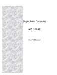
FlashDisk Programmer Board
The FlashDisk Programmer Board accessory, model number ACC-IDEEXT, may be used for several purposes. Its
primary purpose is to enable the simultaneous connection of both a FlashDisk module and a standard IDE hard drive
or CD-ROM drive, to allow file transfers to/from the FlashDisk. This operation is normally done at system setup.
The board can also be used to enable the simultaneous connection of two drives to the SBC.
Connector J1 connects to the IDE connector on Pegasus with a 44-pin ribbon cable (Diamond Systems part no.
6981004). Both 40-pin .1-inch spacing, J4, and 44-pin 2mm spacing, J3, headers are provided for the external hard
drive or CD-ROM drive. A dedicated connector, J2, is provided for the FlashDisk module. Any two devices may
be connected simultaneously using this board with proper master/slave jumper configurations on the devices.
The FlashDisk Programmer Board comes with a 44-wire cable no. (DSC no. 6981004) and a 40-wire cable no.
(DSC no. C-40-18) for connection to external drives. The FlashDisk module is sold separately.
The 44-pin connector (J1, J2 and J3) and mating cable carry power, but the 40-pin connector and mating cable do
not. Connectors J5 and J6 on the accessory board may be used to provide power to a 44-pin device attached to the
board when the board is attached to a PC via a 40-pin cable. These headers are compatible with the floppy drive
power connector on a standard PC internal power cable.
Figure 11: FlashDisk Programmer Board Layout
Diamond Systems Corporation
Pegasus User Manual
Page 41
I/O Cables
Diamond Systems offers cable kit C-PGS-KIT with the following cables to connect to all I/O headers on the board.
Some cables are also available separately.
Figure 12: Pegasus Cable Kit (C-PGS-KIT)
Photo No.
1
2
3
4
5
6
7
8
9
10
Diamond Systems Corporation
Cable No.
6981175
6981162
6981006
6981171
6981161
6981180
6981084
6981081
6981004
6981165
Description
Power in
Keyboard/mouse
Power out
Dual USB (quantity 2)
RJ45
External battery
VGA
2x Serial Port COM1/2
44-Position ribbon HDD, IDE
Miscellaneous
Pegasus User Manual
Page 42
Specifications
CPU
•
•
•
•
•
Processor: AMD Geode LX800
Speed: 500MHz
Power consumption: 5W
Cooling: Fanless
Operating Temperature: -40 to +85ºC
Bus and Memory
•
•
•
System Bus: 100MHz
SDRAM memory: 256MB 533MHz DDR2 soldered on-board
Bus interface: PC/104-Plus (ISA+PCI)
Peripherals
•
•
•
•
•
•
•
•
•
Display type: CRT or 18/24-bit dual channel LVDS flat panel
CRT resolution: 1600 x 1200
Flat Panel Resolution : UXGA 1280x1024
Video memory: 64MB UMA
USB ports: (4) USB 2.0
Serial ports: (1) RS-232 and (1) RS-232/422/485
Networking: 10/100Base-T Ethernet
Mass storage interfaces: (1) IDE UDMA 33, Fashdisk interface
Keyboard/mouse: PS/2
Power Supply
•
Input Voltage: +5VDC ±5% @ 1.0A, typical
General
•
•
Dimensions: 4.050” x 3.775”
Weight: 4.5 oz.
Additional Information
Additional information can be found at the following websites.
•
•
Diamond Systems Corporation: http://www.diamondsystems.com
AMD Geode LX Processor Family, Technical Specifications: http://www.amd.com/usen/ConnectivitySolutions/ProductInformation/0,,50_2330_9863_13022%5E13058,00.html
Technical Support
For technical support, please email [email protected] or contact Diamond Systems technical support at
1-650-810-2500.
Diamond Systems Corporation
Pegasus User Manual
Page 43
Appendix A – BIOS CMOS Option Listing
This section describes the steps for modifying the BIOS settings and describes the BIOS screens.
Viewing and Modifying the BIOS Settings
During board startup, repeatedly press the delete key <Del> to enter BIOS setup mode.
The main page displays the following menu options.
•
•
•
•
•
•
•
•
•
Standard CMOS Features
Advanced Chipset Features
Integrated Peripherals
PnP/PCI Configurations
PC Health Status
Load Optimized Defaults
Set Password
Save & Exit Setup
Exit Without Saving
Select the menu option to view or modify the BIOS settings for the desired configuration area. The screens
displayed for each area are described, below.
The following keyboard controls for navigating the screen are available on any page, displayed at the bottom of the
page.
Key
Esc
Function
Exit current screen.
up-/down-arrow
Select setup item.
left-/right-arrow
Select menu item.
plus/minus symbols (+/-) Change values.
F1
Help.
F5
Save previous values.
F6
Save default values.
F7
Save optimized default values.
F10
Exit BIOS setup.
At any time, select one of the exit options from the main screen, or press <F10>, to exit BIOS setup mode. At the
prompt, enter Y (yes) to take the selected exit action or N (no) to disregard the exit action and remain in the current
screen.
Diamond Systems Corporation
Pegasus User Manual
Page 44
BIOS Screen Descriptions
This section describes the screen displays for each BIOS setup area.
Where “Change Not Allowed” is indicated, it is because the configuration item is not supported by the current
hardware version. The configuration item is displayed for future expansion.
Standard CMOS Features
Default Value
or
User Entry
Optional Values
System Date
00/00/00
-
Month/day/year.
-
System Time
00:00:00
-
Hours:minutes:seconds; 24-hour
format.
-
IDE Primary Master
-
-
See Primary Master HDD Setup.
-
IDE Primary Slave
-
-
Same as IDE Primary Master.
-
-
EGA/VGA
CGA 40
CGA 80
MONO
Configuration Item
Video
Halt On
-
Comments
Change
Not
Allowed
-
All Errors
No Errors
All, But Keyboard
All, But Diskette
All, But Disk/Key
-
IDE Primary Master/Slave Setup
Configuration Item
IDD HDD Auto-Detection
IDE Primary Master
Access Mode
Diamond Systems Corporation
Default Value
or
User Entry
Optional
Values
Comments
When this field is highlighted, press
Enter to auto-detect the HDD size and
configuration parameters. A progress
message displays while the system
detects the installed HDD.
-
-
-
-
None
Auto
Manual
-
-
CHS
LBA
Large
Auto
Change
Not
Allowed
-
-
Pegasus User Manual
-
Page 45
Advanced BIOS Features
Configuration Item
Default Value
or
User Entry
Optional
Values
Comments
First Boot Device
-
HDD-0
Sets the boot device priority. This field
specifies the highest priority device.
CDROM
HDD-1
USB-FDD
USB-ZIP
USB-CDROM
USB-HDD
LAN
Second Boot Device
-
Sets the boot device priority. This field
(Same as FBD) specifies the secong-highest priority
device.
Boot Other Device
-
Disabled
Enabled
Enables or disables booting from the
secondary boot device.
Boot Up NumLock Status
-
Off
On
Sets the numlock state at power-on.
Specifies when a password is required:
only when you enter BIOS setup or
whenever the system boots. The
password is specified using a separate
main menu entry.
Security Option
-
Setup
System
Console Redirection
-
Disabled
Enabled
Enables or disables console redirection.
For console redirection, specifies the
desired baud rate.
Baud Rate
-
9600
19200
38400
57600
115200
Agent Connect via
-
Null
Agent wait time (min)
-
1
2
4
8
Timeout (minutes) to wait to connect to
agent.
Agent after boot
-
Disabled
Enabled
Enables or disables agent running after
OS boot.
Diamond Systems Corporation
Change
Not
Allowed
-
-
-
-
-
The agent connects directly.
Pegasus User Manual
-
-
-
Page 46
Advanced Chipset Features Setup
Configuration Item
Default Value
or
Optional Values
User Entry
Comments
-
-
NONE
8M
16M
32M
64M
128M
254M
-
Output display
-
Flat Panel
CRT
Panel & CRT
Flat Panel Configuration
-
-
Memory Hole At 15M-16M
-
Disabled
Enabled
Video Memory Size
Change
Not
Allowed
-
See Flat Panel Configuration Setup.
-
-
Flat Panel Configuration Setup
Configuration Item
Resolution
Refresh Rate
Diamond Systems Corporation
Default Value
or
Optional Values
User Entry
Comments
Specifies flat panel resolution.
-
320 X 240
640 X 480
800 X 600
1024 X 768
1152 X 864
1280 X 1024
1600 X 1200
800 X 480
Specifies flat panel refresh rate.
-
60 Hz
70 Hz
72 Hz
75 Hz
85 Hz
90 Hz
100 Hz
Change
Not
Allowed
-
Pegasus User Manual
-
Page 47
Integrated Peripherals Setup
Default
Value or
User Entry
Optional
Values
OnChip IDE Device
-
-
See OnChip IDE Device Setup.
-
SuperIO Device
-
-
See SuperIO Device Setup.
-
IT8888 ISA Decode IO
-
-
See IT8888 ISA Decode IO Setup.
-
IT8888 ISA Decode Memory
-
-
See IT8888 ISA Decode Memory Setup.
-
IT8888 DDMA
-
-
See IT8888 DDMA Setup.
-
Onboard Lan Boot ROM
-
Enabled
Disabled
Enables or disables invoking the onboard boot ROM on the on-board LAN
chip.
-
Init Display First
-
PCI Slot
Onboard
-
Configuration Item
Comments
Change
Not
Allowed
-
OnChip IDE Device Setup
Default
Value or
User Entry
Optional Values
Master Drive PIO Mode
-
Auto
Mode 0
Mode 1
Mode 2
Mode 3
Mode 4
Slave Drive PIO Mode
-
IDE Primary Master UDMA
-
Disabled
Auto
-
IDE Primary Slave UDMA
-
Disabled
Auto
-
IDE DMA transfer access
-
Disabled
Enabled
-
Configuration Item
IDE HDD Block Mode
Diamond Systems Corporation
-
Comments
-
-
(Same as Master Drive PIO Mode)
Disabled
Enabled
Pegasus User Manual
Change
Not
Allowed
If your HDD supports block
mode, select Enable to autodetect the optimum number of
read/writers per sector the HDD
supports.
-
-
Page 48
SuperIO Device Setup
Default
Value or
User Entry
Optional Values
Serial Port 1
-
Disabled
3F8/IRQ4
2F8/IRQ3
3E8/IRQ4
2E8/IRQ3
Auto
Serial Port 2
-
Brightness Control
-
Low
High
Default
Value or
User Entry
Optional Values
-
Disabled
Enabled
-
Decode I/O Speed n
-
Subtractive Speed
Slow Speed
Medium Speed
Fast Speed
Decode I/O Addr. n
-
Min = xxxx
Max = xxxx
-
1 Bytes
2 Bytes
4 Bytes
8 Bytes
16 Bytes
32 Bytes
64 Bytes
128 Bytes
Configuration Item
Comments
Change
Not
Allowed
-
(Same as Serial Port 1) -
-
-
-
IT8888 ISA Decode IO Setup
Configuration Item
Decode I/O Space n
Decode I/O Size n
Diamond Systems Corporation
Pegasus User Manual
Comments
Change
Not
Allowed
-
-
“Key in a HEX number”
-
-
-
Page 49
IT8888 ISA Decode Memory Setup
Configuration Item
Decode Memory Space n
Decode Memory Speed n
Decode Memory Addr. n
Decode MemorySize n
Default
Value or
User Entry
Optional Values
-
Disabled
Enabled
-
Subtractive Speed
Slow Speed
Medium Speed
Fast Speed
-
Min = nnnn
Max = nnnn
This field can only be modified
if Decode Memory Space n is
Enabled.
-
16 KB
32 KB
64 KB
128 KB
256 KB
512 KB
1 MB
2 MB
Default
Value or
User Entry
Optional Values
Comments
-
Disabled
Enabled
Comments
-
Change
Not
Allowed
-
This field can only be modified
if Decode Memory Space n is
Enabled.
This field can only be modified
if Decode Memory Space n is
Enabled.
Key in a HEX number.
-
-
-
IT8888 DDMA Setup
Configuration Item
DDMAn Support
Diamond Systems Corporation
Pegasus User Manual
-
Change
Not
Allowed
-
Page 50
PnP/PCI Configurations Setup
Configuration Item
Default Value
or
User Entry
Optional Values
Comments
If you are using a plug-andplay capable OS, select Yes.
Otherwise, select No to have
the BIOS configure the nonboot devices.
Change
Not
Allowed
-
No
Yes
Reset Configuration Data
Disabled
Enabled
Disabled
-
Resources Controlled By
-
Auto(ESCD)
Manual
-
IRQ Resources
-
See IRQ Resources Setup.
-
Memory Resources
-
See Memory Resources Setup.
-
PCI/VGA Palette Snoop
-
Disabled
Enabled
Default
Value or
User Entry
Optional Values
Comments
Change
Not
Allowed
-
PCI Device
Reserved
Select PCI Device for PCI or
ISA devices compliant with the
plug-and-play architecture.
Used to configure IRQs 3, 4, 5,
9, 10, 11 and 12.
-
Default
Value or
User Entry
Optional Values
Comments
Change
Not
Allowed
-
N/A
C800
CC00
D000
D400
D800
DC00
-
8K
16K
32K
64K
PNP OS Installed
-
-
-
-
IRQ Resources Setup
Configuration Item
IRQ-n assisnged to
Memory Resources Setup
Configuration Item
Reserved Memory Base
Reserved Memory Length
Diamond Systems Corporation
Pegasus User Manual
-
-
This field can only be modified
if a non-N/A Memory Base is
selected.
-
Page 51
PC Health Status
Select the PC Health Status menu item to monitor the following parameters:
Parameter
Description
Current CPU Temperature
CPU VCore
MEM Vcore
VCC3
+5V
+12V
VBAT(V)
Load Optimized Defaults
Selecting the Load Optimized Defaults menu item prompts you to confirm whether or not you want to load the
optimized default values. Enter Y (Yes) or N (No) to take the desired action.
Set Password
You may choose to require a password to protect BIOS parameter modification. Selecting the Set Password menu
item prompts you to define a password. There are no restrictions on the length or character in the password. If you
choose not to require a password, press Enter <CR> without entering anything in the field. A confirmation message
will be displayed indicating that the password is disabled.
Diamond Systems Corporation
Pegasus User Manual
Page 52