1
» Kontron User's Guide «
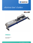
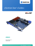
RTM806X
Document Revision 1.0
April 2012
If it's embedded, it's Kontron.
Revision History
Rev. Index
1.0
Brief Description of Changes
Date of Issue
First Release
April 2012
Customer Service
Contact Information:
Kontron Canada, Inc.
4555 Ambroise-Lafortune
Boisbriand, Québec, Canada
J7H 0A4
Tel: (450) 437-5682
(800) 354-4223
Fax: (450) 437-8053
E-mail: [email protected]
Kontron Modular Computer GMBH
Sudetenstrasse 7
87600 Kaufbeuren
Germany
+49 (0) 8341 803 333
+49 (0) 8341 803 339
[email protected]
Visit our site at: www.kontron.com
© 2011 Kontron, an International Corporation. All rights reserved.
The information in this user's guide is provided for reference only. Kontron does not assume any liability
arising out of the application or use of the information or products described herein. This user's guide may
contain or reference information and products protected by copyrights or patents and does not convey any
license under the patent rights of Kontron, nor the rights of others.
Kontron is a registered trademark of Kontron. All trademarks, registered trademarks, and trade names used
in this user's guide are the property of their respective owners. All rights reserved. Printed in Canada. This
user's guide contains information proprietary to Kontron. Customers may reprint and use this user's guide in
other publications. Customers may alter this user's guide and publish it only after they remove the Kontron
name, cover, and logo.
Kontron reserves the right to make changes without notice in product or component design as warranted by
evolution in user needs or progress in engineering or manufacturing technology. Changes that affect the
operation of the unit will be documented in the next revision of this user's guide.
i
RTM806X
www.kontron.com
Table of Contents
Table of Contents
Safety Instructions . . . . . . . . . . . . . . . . . . . . . . . . . . . . . . . . . . . . . . . . . . . . . . . . . . . . . . . vi
Before You Begin . . . . . . . . . . . . . . . . . . . . . . . . . . . . . . . . . . . . . . . . . . . . . . . . . . . . . . . . . . . . . . . vi
Preventing Electrostatic Discharge . . . . . . . . . . . . . . . . . . . . . . . . . . . . . . . . . . . . . . . . . . . . . . . . .vii
Preface . . . . . . . . . . . . . . . . . . . . . . . . . . . . . . . . . . . . . . . . . . . . . . . . . . . . . . . . . . . . . . . . viii
How to Use This Guide . . . . . . . . . . . . . . . . . . . . . . . . . . . . . . . . . . . . . . . . . . . . . . . . . . . . . . . . . . viii
Customer Comments . . . . . . . . . . . . . . . . . . . . . . . . . . . . . . . . . . . . . . . . . . . . . . . . . . . . . . . . . . . . . ix
Advisory Conventions . . . . . . . . . . . . . . . . . . . . . . . . . . . . . . . . . . . . . . . . . . . . . . . . . . . . . . . . . . . . ix
Unpacking . . . . . . . . . . . . . . . . . . . . . . . . . . . . . . . . . . . . . . . . . . . . . . . . . . . . . . . . . . . . . . . . . . . . . .x
Powering Up the System. . . . . . . . . . . . . . . . . . . . . . . . . . . . . . . . . . . . . . . . . . . . . . . . . . . . . . . . . . .x
Storing Boards . . . . . . . . . . . . . . . . . . . . . . . . . . . . . . . . . . . . . . . . . . . . . . . . . . . . . . . . . . . . . . . . . .x
Regulatory Compliance Statements . . . . . . . . . . . . . . . . . . . . . . . . . . . . . . . . . . . . . . . . . . . . . . . . . xi
Limited Warranty . . . . . . . . . . . . . . . . . . . . . . . . . . . . . . . . . . . . . . . . . . . . . . . . . . . . . . . . . . . . . . xii
1.
Product Description . . . . . . . . . . . . . . . . . . . . . . . . . . . . . . . . . . . . . . . . . . . . . . . . . . . . . . . 2
1.1
Product Overview . . . . . . . . . . . . . . . . . . . . . . . . . . . . . . . . . . . . . . . . . . . . . . . . . . . . . . . . . . . . . 2
1.2
What’s Included. . . . . . . . . . . . . . . . . . . . . . . . . . . . . . . . . . . . . . . . . . . . . . . . . . . . . . . . . . . . . . 2
1.3
Board Specifications . . . . . . . . . . . . . . . . . . . . . . . . . . . . . . . . . . . . . . . . . . . . . . . . . . . . . . . . . . 2
1.4
Compliance . . . . . . . . . . . . . . . . . . . . . . . . . . . . . . . . . . . . . . . . . . . . . . . . . . . . . . . . . . . . . . . . . 3
1.5
Hot-Swap Capability . . . . . . . . . . . . . . . . . . . . . . . . . . . . . . . . . . . . . . . . . . . . . . . . . . . . . . . . . . 4
1.6
Interfacing with the Environment . . . . . . . . . . . . . . . . . . . . . . . . . . . . . . . . . . . . . . . . . . . . . . . 4
1.6.1
2.
RTM (rear transition module) . . . . . . . . . . . . . . . . . . . . . . . . . . . . . . . . . . . . . . . . . . . . . . . .4
Board Features . . . . . . . . . . . . . . . . . . . . . . . . . . . . . . . . . . . . . . . . . . . . . . . . . . . . . . . . . . . 7
2.1
Block Diagram . . . . . . . . . . . . . . . . . . . . . . . . . . . . . . . . . . . . . . . . . . . . . . . . . . . . . . . . . . . . . . . 7
2.2
USB 2.0 Interface . . . . . . . . . . . . . . . . . . . . . . . . . . . . . . . . . . . . . . . . . . . . . . . . . . . . . . . . . . . . 8
2.3
SAS . . . . . . . . . . . . . . . . . . . . . . . . . . . . . . . . . . . . . . . . . . . . . . . . . . . . . . . . . . . . . . . . . . . . . . . . 8
2.4
HD Hot-Swap Option . . . . . . . . . . . . . . . . . . . . . . . . . . . . . . . . . . . . . . . . . . . . . . . . . . . . . . . . . . 9
2.5
SFP . . . . . . . . . . . . . . . . . . . . . . . . . . . . . . . . . . . . . . . . . . . . . . . . . . . . . . . . . . . . . . . . . . . . . . . . 9
2.6
MMC Boot Block . . . . . . . . . . . . . . . . . . . . . . . . . . . . . . . . . . . . . . . . . . . . . . . . . . . . . . . . . . . . . . 9
ii
RTM806X
www.kontron.com
Table of Contents
2.7
2.7.1
Sensor Data Record (SDR). . . . . . . . . . . . . . . . . . . . . . . . . . . . . . . . . . . . . . . . . . . . . . . . . . .9
2.7.2
Hardware Sensors . . . . . . . . . . . . . . . . . . . . . . . . . . . . . . . . . . . . . . . . . . . . . . . . . . . . . . . .10
2.7.3
Field Replaceable Unit (FRU) Information . . . . . . . . . . . . . . . . . . . . . . . . . . . . . . . . . . . . .11
2.7.4
MMC Firmware Code . . . . . . . . . . . . . . . . . . . . . . . . . . . . . . . . . . . . . . . . . . . . . . . . . . . . . .13
2.7.5
MMC Firmware Upgrade Procedure . . . . . . . . . . . . . . . . . . . . . . . . . . . . . . . . . . . . . . . . . . .13
2.7.6
Hot-Swap Process . . . . . . . . . . . . . . . . . . . . . . . . . . . . . . . . . . . . . . . . . . . . . . . . . . . . . . . .13
2.8
3.
Hot Swap LED (LED0) . . . . . . . . . . . . . . . . . . . . . . . . . . . . . . . . . . . . . . . . . . . . . . . . . . . . .14
2.8.2
Out Of Service (LED1) . . . . . . . . . . . . . . . . . . . . . . . . . . . . . . . . . . . . . . . . . . . . . . . . . . . . .14
2.8.3
Healthy LED (LED2). . . . . . . . . . . . . . . . . . . . . . . . . . . . . . . . . . . . . . . . . . . . . . . . . . . . . . .15
2.8.4
RTM HDD 1 and 2 Hot Swap LED . . . . . . . . . . . . . . . . . . . . . . . . . . . . . . . . . . . . . . . . . . . . .15
Hot Swap and Installation. . . . . . . . . . . . . . . . . . . . . . . . . . . . . . . . . . . . . . . . . . . . . . . . . 17
Installing the RTM in the chassis. . . . . . . . . . . . . . . . . . . . . . . . . . . . . . . . . . . . . . . . . . . . .17
3.1.2
Removing the RTM from the chassis . . . . . . . . . . . . . . . . . . . . . . . . . . . . . . . . . . . . . . . . . .17
D.
RTM HDD Hot Swap and Installation . . . . . . . . . . . . . . . . . . . . . . . . . . . . . . . . . . . . . . . . . . . . . 18
3.2.1
Installing the Hot Swap RTMHDD . . . . . . . . . . . . . . . . . . . . . . . . . . . . . . . . . . . . . . . . . . . .18
3.2.2
Removing the Hot Swap RTMHDD . . . . . . . . . . . . . . . . . . . . . . . . . . . . . . . . . . . . . . . . . . . .18
Connector Pinouts . . . . . . . . . . . . . . . . . . . . . . . . . . . . . . . . . . . . . . . . . . . . . . . . . . . . . . .A-1
A.1
Connectors and Headers Summary . . . . . . . . . . . . . . . . . . . . . . . . . . . . . . . . . . . . . . . . . . . . . .A-1
A.2
AdvancedTCA I/O RTM Connector (J30) . . . . . . . . . . . . . . . . . . . . . . . . . . . . . . . . . . . . . . . . .A-2
A.3
Serial Port(J1). . . . . . . . . . . . . . . . . . . . . . . . . . . . . . . . . . . . . . . . . . . . . . . . . . . . . . . . . . . . . .A-3
A.4
SFP+ Channel (J4 & J5) . . . . . . . . . . . . . . . . . . . . . . . . . . . . . . . . . . . . . . . . . . . . . . . . . . . . . . .A-3
A.5
Dual USB Port (J7) . . . . . . . . . . . . . . . . . . . . . . . . . . . . . . . . . . . . . . . . . . . . . . . . . . . . . . . . . .A-4
A.6
Hot Swap Hard Disk Module(J7 & J8) . . . . . . . . . . . . . . . . . . . . . . . . . . . . . . . . . . . . . . . . . . . .A-4
Software Update . . . . . . . . . . . . . . . . . . . . . . . . . . . . . . . . . . . . . . . . . . . . . . . . . . . . . . . .B-1
B.1
C.
RTM Hot Swap and Installation . . . . . . . . . . . . . . . . . . . . . . . . . . . . . . . . . . . . . . . . . . . . . . . . . 17
3.1.1
3.2
B.
Face Plate Indicators . . . . . . . . . . . . . . . . . . . . . . . . . . . . . . . . . . . . . . . . . . . . . . . . . . . . . . . . . 14
2.8.1
3.1
A.
Hardware Management Overview . . . . . . . . . . . . . . . . . . . . . . . . . . . . . . . . . . . . . . . . . . . . . . . . 9
MMC Firmware Update Procedure . . . . . . . . . . . . . . . . . . . . . . . . . . . . . . . . . . . . . . . . . . . . . . .B-1
Getting Help . . . . . . . . . . . . . . . . . . . . . . . . . . . . . . . . . . . . . . . . . . . . . . . . . . . . . . . . . . . . C-1
C.1
Returning Defective Merchandise. . . . . . . . . . . . . . . . . . . . . . . . . . . . . . . . . . . . . . . . . . . . . . . C-1
C.2
When Returning a Unit . . . . . . . . . . . . . . . . . . . . . . . . . . . . . . . . . . . . . . . . . . . . . . . . . . . . . . . C-2
Glossary . . . . . . . . . . . . . . . . . . . . . . . . . . . . . . . . . . . . . . . . . . . . . . . . . . . . . . . . . . . . . . D-1
iii
RTM806X
www.kontron.com
List of Figures
List of Figures
Figure 2-1: Block Diagram . . . . . . . . . . . . . . . . . . . . . . . . . . . . . . . . . . . . . . . . . . . . . . . . . . . . . . . . . . . . . .7
iv
RTM806X
www.kontron.com
List of Tables
List of Tables
Table 1-1 Board Specifications . . . . . . . . . . . . . . . . . . . . . . . . . . . . . . . . . . . . . . . . . . . . . . . . . . . . . . . . . . 2
Table 2-1 USB Connector Pinout . . . . . . . . . . . . . . . . . . . . . . . . . . . . . . . . . . . . . . . . . . . . . . . . . . . . . . . . . 8
Table 2-2 IPMI Hardware Sensors . . . . . . . . . . . . . . . . . . . . . . . . . . . . . . . . . . . . . . . . . . . . . . . . . . . . . . . 10
Table 2-3 Board Information Area. . . . . . . . . . . . . . . . . . . . . . . . . . . . . . . . . . . . . . . . . . . . . . . . . . . . . . . 11
Table 2-4 Product Information Area . . . . . . . . . . . . . . . . . . . . . . . . . . . . . . . . . . . . . . . . . . . . . . . . . . . . . 12
Table 2-5 Type 16 Module Current Requirements Records . . . . . . . . . . . . . . . . . . . . . . . . . . . . . . . . . . . . . 12
Table 2-6 Hot-Swap LED Description . . . . . . . . . . . . . . . . . . . . . . . . . . . . . . . . . . . . . . . . . . . . . . . . . . . . . 14
v
RTM806X
www.kontron.com
Safety Instructions
Safety Instructions
Before You Begin
Before handling the board, read the instructions and safety guidelines on the following pages to prevent
damage to the product and to ensure your own personal safety. Refer to the "Advisories" section in the
Preface for advisory conventions used in this user's guide, including the distinction between Warnings,
Cautions, Important Notes, and Notes.
• Always use caution when handling/operating the computer. Only qualified, experienced,
authorized electronics service personnel should access the interior of the computer. The power
supplies produce high voltages and energy hazards, which can cause bodily harm.
• Use extreme caution when installing or removing components. Refer to the installation
instructions in this user's guide for precautions and procedures. If you have any questions, please
contact Kontron Technical Support
WARNING
High voltages are present inside the chassis when the unit's power cord is plugged
into an electrical outlet. Turn off system power, turn off the power supply, and then
disconnect the power cord from its source before removing the chassis cover. Turning
off the system power switch does not remove power to components.
vi
RTM806X
www.kontron.com
Safety Instructions
Preventing Electrostatic Discharge
Static electricity can harm system boards. Perform service at an ESD workstation and follow proper ESD
procedure to reduce the risk of damage to components. Kontron strongly encourages you to follow proper
ESD procedure, which can include wrist straps and smocks, when servicing equipment.
Take the following steps to prevent damage from electrostatic discharge (ESD):
•When unpacking a static-sensitive component from its shipping carton, do not remove the
component's antistatic packing material until you are ready to install the component in a
computer. Just before unwrapping the antistatic packaging, be sure you are at an ESD workstation
or grounded. This will discharge any static electricity that may have built up in your body.
•When transporting a sensitive component, first place it in an antistatic container or packaging.
•Handle all sensitive components at an ESD workstation. If possible, use antistatic floor pads and
workbench pads.
•Handle components and boards with care. Don't touch the components or contacts on a board. Hold
a board by its edges or by its metal mounting bracket.
•Do not handle or store system boards near strong electrostatic, electromagnetic, magnetic, or
radioactive fields.
•When you want to remove the protective foil (if present), make sure you are properly grounded and
that you touch a metalic part of the board.
CAUTION
Removing the protective foil from the top and bottom cover might create static.
When you remove those protections, make sure you follow the proper ESD procedure.
vii
RTM806X
www.kontron.com
Preface
Preface
How to Use This Guide
This user's guide is designed to be used as step-by-step instructions for installation, and as a reference for
operation, troubleshooting, and upgrades.
For the circuits, descriptions and tables indicated, Kontron assumes no responsibility as far as patents or
other rights of third parties are concerned.
The following is a summary of chapter contents:
•Chapter 1, Product Description
•Chapter 2, Board Features
•Chapter 3, Installing the board
•Appendix A, Connector Pinout
•Appendix B, Software Update
•Appendix C, Getting Help
•Appendix D, Glossary
viii
RTM806X
www.kontron.com
Preface
Customer Comments
If you have any difficulties using this user's guide, discover an error, or just want to provide some feedback,
please send a message to: [email protected]. Detail any errors you find. We will correct the errors
or problems as soon as possible and post the revised user's guide on our Web site. Thank you.
Advisory Conventions
Seven types of advisories are used throughout the user guides to provide helpful information or to alert you
to the potential for hardware damage or personal injury. They are Note, Signal Paths, Jumpers Settings, BIOS
Settings, Software Usage, Cautions, and Warnings. The following is an example of each type of advisory. Use
caution when servicing electrical components.
Note:
Indicate information that is important for you to know.
Signal Path:
Indicate the places where you can find the signal on the board.
Jumper Settings:
Indicate the jumpers that are related to this section.
BIOS Settings:
Indicate where you can set this option in the BIOS.
Software Usage:
Indicates how you can access this feature through software.
CAUTION
Indicate potential damage to hardware and tells you how to avoid the problem.
WARNING
Indicates potential for bodily harm and tells you how to avoid the problem.
ESD Sensitive Device:
This symbol and title inform that electronic boards and their components are sensitive to static
electricity. Therefore, care must be taken during all handling operations and inspections of this
product, in order to ensure product integrity at all times.
Please read also the section "Special Handling and Unpacking Instructions".
CE Conformity:
This symbol indicates that the product described in this manual is in compliance with all applied CE
standards. Please refer also to the section "Regulatory Compliance Statements" in this manual.
Disclaimer: We have tried to identify all situations that may pose a warning or a caution condition in this
user's guide. However, Kontron does not claim to have covered all situations that might require the use of a
Caution or a Warning.
ix
RTM806X
www.kontron.com
Preface
Unpacking
Follow these recommendations while unpacking:
•Remove all items from the box. If any items listed on the purchase order are missing, notify Kontron
customer service immediately.
•Inspect the product for damage. If there is damage, notify Kontron customer service immediately.
•Save the box and packing material for possible future shipment.
Powering Up the System
Before any installation or setup, ensure that the board is unplugged from power sources or subsystems.
If you encounter a problem, verify the following items:
•Make sure that all connectors are properly connected.
•Verify your boot devices.
•If the system does not start properly, try booting without any other I/O peripherals attached,
including AMC adapters.
Make sure your system provides the minimum DC voltages required at the board's slot, especially if DC power
is carried by cables.
If you are still not able to get your board running, contact our Technical Support for assistance.
Storing Boards
Electronic boards are sensitive devices. Do not handle or store device near strong electrostatic,
electromagnetic, magnetic or radioactive fields.
x
RTM806X
www.kontron.com
Preface
Regulatory Compliance Statements
FCC Compliance Statement for Class A Devices
This equipment has been tested and found to comply with the limits for a Class A digital device,
pursuant to Part 15 of the FCC Rules. These limits are designed to provide reasonable protection
against harmful interference in a residential installation. This equipment generated, uses and can
radiate radio frequency energy and, if not installed and used in accordance with the instructions
may cause harmful interference to radio communications. However, there is no guarantee that
interference will not occur in a particular installation. If this equipment does cause harmful
interference to radio or television reception, which can be determined by turning the equipment
off and on, the user is encouraged to try to correct the interference by one or more of the following
measures:
•Reorient or relocate the receiving antenna.
•Increase the separation between the equipment and receiver.
•Connect the equipment into an outlet on a circuit different from that to which the receiver is
connected.
•Consult the dealer or an experience radio/TV technician for help.
WARNING
This is a Class A product. If not installed in a properly shielded enclosure and used in
accordance with this User's Guide, this product may cause radio interference in
which case users may need to take additional measures at their own expense.
Safety Certification
All Kontron equipment meets or exceeds safety requirements based on the IEC/EN/UL/CSA 609501 family of standards entitled, "Safety of information technology equipment." All components are
chosen to reduce fire hazards and provide insulation and protection where necessary. Testing and
reports when required are performed under the international IECEE CB Scheme. Please consult the
"Kontron Safety Conformity Policy Guide" for more information. For Canada and USA input voltage
must not exceed -60Vdc for safety compliance.
CE Certification
The product(s) described in this user's guide complies with all applicable European Union (CE)
directives if it has a CE marking. For computer systems to remain CE compliant, only CE-compliant
parts may be used. Maintaining CE compliance also requires proper cable and cabling techniques.
Although Kontron offers accessories, the customer must ensure that these products are installed
with proper shielding to maintain CE compliance. Kontron does not offer engineering services for
designing cabling systems. In addition, Kontron will not retest or recertify systems or components
that have been reconfigured by customers.
xi
RTM806X
www.kontron.com
Preface
Limited Warranty
Kontron grants the original purchaser of Kontron's products a TWO YEAR LIMITED HARDWARE WARRANTY as
described in the following. However, no other warranties that may be granted or implied by anyone on behalf
of Kontron are valid unless the consumer has the express written consent of Kontron.
Kontron warrants their own products, excluding software, to be free from manufacturing and material
defects for a period of 24 consecutive months from the date of purchase. This warranty is not transferable nor
extendible to cover any other users or long- term storage of the product. It does not cover products which
have been modified, altered or repaired by any other party than Kontron or their authorized agents.
Furthermore, any product which has been, or is suspected of being damaged as a result of negligence,
improper use, incorrect handling, servicing or maintenance, or which has been damaged as a result of
excessive current/voltage or temperature, or which has had its serial number(s), any other markings or parts
thereof altered, defaced or removed will also be excluded from this warranty.
If the customer's eligibility for warranty has not been voided, in the event of any claim, he may return the
product at the earliest possible convenience to the original place of purchase, together with a copy of the
original document of purchase, a full description of the application the product is used on and a description
of the defect. Pack the product in such a way as to ensure safe transportation (see our safety instructions).
Kontron provides for repair or replacement of any part, assembly or sub-assembly at their own discretion, or
to refund the original cost of purchase, if appropriate. In the event of repair, refunding or replacement of
any part, the ownership of the removed or replaced parts reverts to Kontron, and the remaining part of the
original guarantee, or any new guarantee to cover the repaired or replaced items, will be transferred to cover
the new or repaired items. Any extensions to the original guarantee are considered gestures of goodwill, and
will be defined in the "Repair Report" issued by Kontron with the repaired or replaced item.
Kontron will not accept liability for any further claims resulting directly or indirectly from any warranty
claim, other than the above specified repair, replacement or refunding. In particular, all claims for damage
to any system or process in which the product was employed, or any loss incurred as a result of the product
not functioning at any given time, are excluded. The extent of Kontron liability to the customer shall not
exceed the original purchase price of the item for which the claim exists.
Kontron issues no warranty or representation, either explicit or implicit, with respect to its products
reliability, fitness, quality, marketability or ability to fulfil any particular application or purpose. As a result,
the products are sold "as is," and the responsibility to ensure their suitability for any given task remains that
of the purchaser. In no event will Kontron be liable for direct, indirect or consequential damages resulting
from the use of our hardware or software products, or documentation, even if Kontron were advised of the
possibility of such claims prior to the purchase of the product or during any period since the date of its
purchase.
Please remember that no Kontron employee, dealer or agent is authorized to make any modification or
addition to the above specified terms, either verbally or in any other form, written or electronically
transmitted, without the company's consent.
xii
RTM806X
www.kontron.com
Chapter 2
Board Features
1.1
1.2
1.3
1.4
1.5
1.6
Product Overview .............................................. 2
What’s Included ................................................ 2
Board Specifications .......................................... 2
Compliance ...................................................... 3
Hot-Swap Capability .......................................... 4
Interfacing with the Environment ......................... 4
www.kontron.com
1. Product Description
1.1
Product Overview
The RTM806X is a single slot (6HP) AdvancedTCA Rear Transition Module. This RTM provides additional
connectivity and storage functionality to the AT8060 CPU front board.
1.2
What’s Included
This board is shipped with the following items:
• One RTM806X board
• Two Hard Disk Carriers with their respective HDD, already mounted on the RTM806X board.
• One CD-ROM containing documentations.
If any item is missing or damaged, contact the supplier.
1.3
Board Specifications
Table 1-1:Board Specifications
Features
Description
Compliancy
•
•
•
•
•
•
PICMG3.0 R3.0 (see note in section 1.4)
SAS1R10
SFF-8088
IEEE 802.3z (fiber interface)
PICMG HPM.1
USB 2.0
•
•
•
Management Controller compliant to PICMG 3.0, IPMI v2.0 and AMC.0 R2.0.
Management Controller is run time field reprogrammable without payload impact.
Robust fail safe reprogramming implementation (which includes two firmware images) that
performs an automatic or manual rollback if a problem occurs during critical reprogramming
phase.
Remote upgrade capability (via IPMB).
Management Controller self test which can detect a failure in its code integrity and trigger an
automatic rollback.
IPMI Features
•
•
•
Hardware system monitor(sensors, alarm, events) through IPMI (voltages, temperatures),
power failure.
Mechanical
•
350.93 X 176.8 X 28.95 mm
Power Requirements
•
•
10W Typical without hard drive.
65W Maximum with hard drives.
Supervisory
2
RTM806X
www.kontron.com
Features
Description
Environmental
Temperature*
Operating: 0-55°C/32-131°F with 3.8 CFM airflow
Storage and Transit: -40 to +70°C/-40 to 158°F
Environmental
Humidity*
Operating: 15% to 90% @55°C/131°F non-condensing
Storage and Transit: 5% to 95% @ 40°C/104°F non-condensing
Environmental Altitude*
Operating: 4,000 m / 13,123 ft
Storage and Transit: 15,000 m / 49,212 ft
Environmental Shock*
Operating: 3G, half-sine 11ms, each axis
Storage and Transit: 18G, half-sine 11ms, each axis
Environmental
Vibration*
Operating: 5-200Hz. 0.2G, each axis
Storage and Transit: 5 Hz to 20 Hz @ 1 m2/s3 (0.01 g2 /Hz) (flat) 20 Hz to 200 Hz @ -3 dB/oct (slope
down)
Reliability
•
•
Whole board protected by an active breaker
USB voltage protected by an active breaker
Safety / EMC
•
•
•
Safety: CE Mark to EN 60950-1:2001. Meets or exceeds UL 60950-1/CSA C22.2 No 60950-1-07.
Designed to meet GR-1089-CORE
EMI/EMC: FCC 47 CFR Part 15, Class A; CE Mark to EN55022/EN55024/EN300386
Warranty
Two years limited warranty
* Designed to meet or exceed
1.4
Compliance
This product conforms to the following specifications:
• USB 2.0 - Universal Serial Bus Version 2.0
• PICMG3.0 R3.0 - Advanced Telecommunication Computing Architecture (see note below)
• PICMG HPM.1
• SAS1R10 - Serial Attached SCSI - 1.0 Revision 10.
• SFF-8088 (T10 Technical Committee and SCSI Trade Association)
• IEEE 802.3z (fiber interface)
• IPMI v2.0
• AMC.0 R2.0
Note:
Board might not be 100% compliant to ATCA PICMG 3.0 Specification REQ 4.94 when a hard drive is
present on the RTMHDD. The HDD might connect the Logic Ground and the Shelf Ground. By default
the Logic Ground and the Shelf Ground are connected through a removable screw.
3
RTM806X
www.kontron.com
Note:
In order to fit two 2.5'' SAS disks, the RTM806X is exceeding the RTM mechanical envelope defined
by ATCA PICMG 3.0 specification, only in HDDs section.
1.5
Hot-Swap Capability
The RTM806X supports Full Hot Swap capability as per PICMG3.0R3.0. It can be removed from or installed in
the system while it is on (without powering-down the system). Please refer to the PICMG3.0R3.0 specification
for additional details.
WARNING
All the managements infrastructures are present for hot-swap, but the user must
take the proper action to protect its data under the OS installed on the Front Board
(such as unmount a SAS drive)
1.6
Interfacing with the Environment
1.6.1
RTM (rear transition module)
The RTM806X is a single slot (6HP) AdvancedTCA Rear Transition Module. This module provides additional
connectivity for AT8060 CPU front board.
1.6.1.1
SAS Feature
• Compliant to SAS 3G (RTM8063), SAS 6G (RTM8066)
• A JBOD unit can be use as additional external storage. This connection is done through a standard miniSAS cable. SAS signal integrity guaranteed over a two meters cable
1.6.1.2
Serial Port Feature
• One (1) serial port available on the RTM face plate through one (1) RJ-45 connector
• RS-232 signals level at RTM face plate connector.
• Serial port speed capability is: 9.6kbits/s to 115.2kbits/s.
1.6.1.3
FRU Data EEPROM
• FRU Data EEPROM size is 4Kbyte and it includes board identification and serial number.
1.6.1.4
Hot Swap
As a Hot Swappable Intelligent Managed FRU, the RTM806X (FRU2) includes a Management Controller, the
AdvancedTCA Hot Swap indicator (Blue LED), and the standard AdvancedTCA handle switch.
4
RTM806X
www.kontron.com
Each HDD is an independent FRU that is hot swappable. The HDD hotswap handle is used to raise an event to
the OS in order to hotswap the HDD without interrupting the front board operation.
1.6.1.5
Insertion and Removal of the Managed FRUs
After insertion, the front board detects and activates the management components of the FRU. When the
handle is closed, the power budget and the e-keying negotiations start. Then, the front board's IPMC
activates the payload components of the FRU.
Opening the RTM handle switch on the RTM FRU will start the deactivation process, which either deactivates
the whole board (front board, RTM and RTMHDD) or only the RTM806X and its RTMHDDS, depending on a
configuration policy available through the CMOS configuration menu. See AT8060 User Manual's appropriate
BIOS section for details.
The operational state of the FRU is reported through the management subsystem’s FRU Hot Swap sensors.
The BLUE LED is 100% off when a FRU is operational and unsafe for extraction. An always on(100%) indicates
that a FRU can safely be extracted; transitional states are identified through blinking patterns. Additional
details on the standard FRU Hot Swap sensor and the BLUE LED usage can be found in the AdvancedTCA
specifications.
5
RTM806X
www.kontron.com
Chapter 2
Board Features
2.1
2.2
2.3
2.4
2.5
2.6
2.7
2.8
Block Diagram .................................................. 7
USB 2.0 Interface .............................................. 8
SAS ................................................................ 8
HD Hot-Swap Option .......................................... 9
SFP................................................................. 9
MMC Boot Block ................................................ 9
Hardware Management Overview .......................... 9
Face Plate Indicators.......................................... 14
www.kontron.com
2. Board Features
2.1
Block Diagram
Figure 2-1:Block Diagram
7
RTM806X
www.kontron.com
2.2
USB 2.0 Interface
The RTM806X features two USB connectors on the faceplate.
USB features include:
•Capability to daisy chain as many as 127 devices per interface
•Fast bi-directional
•Isochronous/asynchronous interface
•480 MBPS transfer rate
•Standardization of peripheral interfaces into a single format
•Backward compatible with USB 1.1 devices
USB supports Plug and Play and hot-swapping operations (OS level). These features allow USB devices to be
automatically attached, configured and detached, without reboot or running setup.
Table 2-1:USB Connector Pinout
Pin
Signal
1
VCC
2
DATA-
3
DATA+
4
GND
Signal Path:
The USB Ports are available through the RTM face plate (J2).
2.3
SAS
The SAS connections are only offered through the RTM. The controller is located on the front board and sends
the four signals from the PCH to the RTM through the RTM connectors. The SAS signals are accessible
through:
• Two HDD mounted on RTM806X
• Two external links through the mini-SAS connector
8
RTM806X
www.kontron.com
2.4
HD Hot-Swap Option
Kontron offers the possibility to add two Hot-Swap SAS hard drives on the RTM806X. Those hard drives are
located on the lower part of the RTM806X. The Hotswap infrastructure includes a Hot-Swap LED, Hot-Swap
handle, hard disk presence status and a thermal sensor. All of which are connected to the MMC. They are
managed by the IPMC and presented as a regular managed FRU to management subsystem.
2.5
SFP
The RTM806X has two SFP modules connectors available on the RTM face plate. The SFP module signals come
from the front board 1000Base-KX interface through the zone 3 connector.
2.6
MMC Boot Block
The MMC runs a firmware from its internal 256KB flash. It is programmed by an additional 8K boot block. It
keeps the last two copies of the MMC firmware in a dedicated flash memory. The boot block activates the MMC
image and can rollback a firmware update in case of problems.
2.7
Hardware Management Overview
The RTM communicates with the front board using the IPMB-L channel. Kontron’s Intelligent RTM address on
the IPMB-L is fixed and has a value of 0xA6.
The memory subsystem of the MMC consists of an integrated flash memory to hold the MMC operation code
and integrated RAM for data. The field replacement unit (FRU) inventory information is stored in the
nonvolatile memory on an EEPROM connected via a local I2C interface to the MMC. It is possible to store up to
4 KBytes within the FRU inventory information. Events are sent over the IPMB-L bus to the front board which
then forwards it to the ShMc to ensure that 'post-mortem' logging information is available even if the power
of the RTM is disabled.
The onboard DC voltages and temperatures are monitored by the MMC device. The MMC will send an event to
the front board if any of the thresholds are exceeded.
To increase the reliability of the RTM806X management subsystem, an external watchdog supervisor is
implemented for the MMC. The MMC must strobe the external watchdog at 500 μsec. intervals to ensure
continuity of operation of the board's management subsystem. If the MMC ceases to strobe the watchdog
supervisor, the watchdog resets the MMC. The watchdog timeout expires after one second if strobes are not
generated. The external watchdog supervisor is not configurable and must not be confused with the IPMI
v1.5 watchdog timer commands. This external watchdog of the MMC is implemented in a separate chip.
2.7.1
Sensor Data Record (SDR)
Every sensor on the RTM is associated with a Sensor Data Record (SDR). Sensor Data Records contain
information about the sensors identification such as sensor’s type, sensor name, sensor unit. SDRs also
9
RTM806X
www.kontron.com
contain the configuration of a specific sensor such as threshold/hystheresis, event generation capabilities
that specify sensor behaviour. Some fields of the sensor SDR are configurable through IPMI v1.5 command
and are set with built-in initial value. Finally, the field ‘sensor owner’ must reflect the module’s address
which allows a system management software to identify the owner of the SDR when it is scanned from the
front board IPMC and merged within the IPMC Device SDR repository.
From an IPMI perspective, the RTM806X management controller is set up as a satellite management
controller (SMC). It does support sensor devices, and uses the IPMI static sensor population feature of IPMI
v1.5 to merge the hotswap RTM sensor with the front board’s sensor population. The SHMC is informed about
an RTM insertion through the RTM Module Hot Swap sensor and a radial presence line on the RTM connector.
All SDRs can be queried using Device SDR commands to the firmware. Module sensors that have been
implemented are listed below.
2.7.2
Hardware Sensors
Table 2-2:IPMI Hardware Sensors
IPMI
sensor
ID
Sensor Name
Description (Sensor Type, Event trigger)
Scanning En- Health LED
abled under (Green to AmPower State ber)
0
IPMI Info-1
Internal Management Controller firmware diagnostic
*
N
1
IPMI Info-2
Internal Management Controller firmware diagnostic
*
N
2
FRU Agent
FRU Information Agent - FRU0 Data Error Detection
*
N
3
Module HS
Hot Swap state
*
N
4
IPMBL State
IPMB-L branch from FRU0 fault detection sensor
*
N
5
MMC Stor Err
Management sub-system health: non volatile memory error
*
N
6
MMC Reboot
IPMC reboot detection
*
N
7
Ver Change
Firmware Change Detection
*
N
8
Temp MMC
Module Management Controller Temperature (Degrees)
*
X
9
Temp SAS HD
Hard disk zone temperature
*
X
10
Temp Air In
Air Inlet Temperature (Degrees)
*
X
11
Temp Air Out
Air Outlet Temperature (Degrees)
*
X
12
Vcc +3.3VSUS
Voltage on board 3.3V suspend (management) power supply
*
X
13
Vpump
Voltage on board blue LED VPUMP suspend power supply
*
X
14
Vcc +12V In
Voltage on board 12V payload power supply
-
X
15
Vcc +5V
Voltage on board 5V backend power supply
-
X
16
Vcc +3.3V
Voltage on board 3.3V backend power supply
-
X
17
Vcc +12V HD
Voltage on board 12V payload disk power supply
-
X
18
SFP1 Status
SFP1 Presence/Fault status
-
X
19
SFP2 Status
SFP2 Presence/Fault status
-
X
20
USB1 OC
USB1 Over Current Status
-
X
21
USB2 OC
USB2 Over Current Status
-
X
22
Disk1 Bay
Removable Disk 1 Bay Slot/Connector Status
*
N
23
Disk2 Bay
Removable Disk 2 Bay Slot/Connector Status
*
N
24
Power State
Board Power State
*
N
10
RTM806X
www.kontron.com
IPMI
sensor
ID
Sensor Name
Description (Sensor Type, Event trigger)
Scanning En- Health LED
abled under (Green to AmPower State ber)
25
Power Good
Actual RTM power good status
-
X
26
Pwr Good HD1
Actual HD1 power good status
-
X
27
Pwr Good HD2
Actual HD1 power good status
-
X
28
Health Error
General health status
*
N
X
Exceed critical threshold / Error Assertion
*
Power On/Off
-
Power On
N
No change
2.7.2.1
IPMB-L Link Sensor
The RTM806X has an IPMB-L link to communicate with the processor board and other devices in the chassis
chassis IPMB-0 bus. MMC monitors the bus for any link failure and sends the bus failure event to the front
board upon the recovery occurs.
2.7.3
Field Replaceable Unit (FRU) Information
The FRU Information provides inventory data about the boards where the FRU Information Device is located.
The part number or version number can be read through software.
FRU information in the RTM806X includes data describing the RTM806X board similar to AMC.0 R2.0
specification requirements. This information is retrieved by the RTM, enabling reporting of board-specific
information through a standardized mechanism.
Table 2-3:Board Information Area
Board Information Area
Field Description
Value (hex)
Format Version
0x01
Board Area Length
*Calculated
Language code
0x00
Manufacturing Date / Time
*Based on mfg. date
Board Manufacturer type/length
*Calculated
Board Manufacturer
“Kontron”
Board Product Name type/length
*Calculated
Board Product Name
“RTM806X”
Board Serial Number type/length
*Calculated
Board Serial Number
Manufacturer S/N
Board Part Number type/length
*Calculated
Board Customer Part Number
"T5707###_R"
FRU File ID type/length
*Calculated
11
RTM806X
www.kontron.com
Board Information Area
FRU File ID
"FRU5707-YY"
No more fields
0xC1
Padding
0x00
Board Area Checksum
*Calculated
Table 2-4:Product Information Area
Product Information Area
Field Description
Value (hex)
Format Version
0x01
Product Area Length
*Calculated
Language Code
0x00
Manufacturer Name type/length
*Calculated
Manufacturer Name
“Kontron”
Product Name type/length
*Calculated
Product Name
“RTM806X”
Product Part/Model Number type/length
*Calculated
Product Part/Model Number
"T5707_XX"*
Product Version type/length
*Calculated
Product Version
“XX” *
Product Serial Number type/length
*Calculated
Product Serial Number
Manufacturer S/N
Asset Tag type/length
0xC0
Asset Tag
FRU File ID type/length
*Calculated
FRU File ID bytes
"FRU5707-YY"**
No more fields
0xC1
Padding
0x00
Product Info Area Checksum
*Calculated
Table 2-5:Type 16 Module Current Requirements Records
Type 16 – Module Current Requirements Record
Record Type ID
C0h
Record format version
02h
Manufacturer ID
00315Ah (PICMG Record ID)
PICMG Record ID
16h (Module Power Descriptor table)
Record Format Version
00h
Current Draw
04h (0.4 Amps at 12 V -> 4.8 Watts)
12
RTM806X
www.kontron.com
2.7.4
MMC Firmware Code
MMC firmware code is organized into boot code and operational code, both of which are stored in a flash
module. Upon an MMC reset, the MMC executes the boot code and performs the following:
1-Self test to verify the status of its hardware and memory.
2-Performs a checksum of the operational code.
3-Set operational state that tells the boot block that the firmware is operating correctly.
Upon successful verification of the operational code checksum, the firmware will jump to the operational
code.
2.7.5
MMC Firmware Upgrade Procedure
The upgrade procedure is compliant to PICMG HPM.1. MMC Firmware upgrades can be done by using IPMITOOL
from sourceforge from the front board or remotely on the chassis. It has been designed to upgrade through
any IPMI interface without payload impact.
2.7.6
Hot-Swap Process
The RTM806X has the ability to be hot-swapped in and out of the front board. The onboard MMC manages the
RTM's power-up and power-down transitions. The list below illustrates this process for power down request.
1-Ejector latch is opened. HOT_SWAP_PB# assertion. MMC firmware detects the assertion of this
signal.
2-MMC sends "Module Handle Open" event message to the front board. The corresponding M state of
the front board moves from M4-> M5.
3-The front board moves from M5 -> M6 if the SHMC grants the request. The front board IPMC sends the
FRU control requesting quiesced state to the RTM.
4-The firmware deasserts payload power and sends "Module Quiesced" event message to the front
board where it transitions from M6 to M1 state.
Note:
Depending on your BIOS configuration, a hot-swap process might turn off the front board. Please
refer to the BIOS section “Managed FRU Deactivate Policies” of the AT8060.
2.7.6.1
Hot-Swap LED
The RTM806X and both RTM HDD support a blue Hot Swap LED mounted on the front panel. This LED indicates
when it is safe to remove the RTM from the front board or the hard disk from the RTM. The on-board MMC
drives this LED to indicate the hot-swap state. The following states are possible:
13
RTM806X
www.kontron.com
Table 2-6:Hot-Swap LED Description
LED state
Description
OFF
M4 state; normal state when board is in operation.
ON
M1 state; ready for hot swap.
Short blink
M5 state; deactivation request
Long blink
M2 state; activation request.
When the RTM latch is disengaged from the faceplate, the hot swap switch embedded in the PCB will assert a
"HOT_SWAP_PB#" signal to the MMC, and the MMC will send “Module Handle Open” event message to the
front board which moves from the M4 state to the M5 state. At the M5 state, the front board will ask the SHMC
(or Shelf Manager) for permission to move the RTM to the M6 state. Then the IPMC of the front board, through
IPMB-L, will set the RTM/HDD Hot Swap LED to indicate this state with a short blink. Once permission is
received from the SHMC or higher-level software, the front board will move to the M6 state.
The SHMC or higher level software can reject the request to move to the M6 state. If this occurs, the RTM/HDD
will returns the Hot Swap LED to a solid off condition, indicating that the RTM has returned to M4 state.
If the RTM/HDD reaches the M6 state through an extraction request through the RTM/HDD handle latch, the
MMC communicates to the front board that the module must discontinue operation in preparation for
removal. The Hot Swap LED continues to flash during this preparation time, just like it does at the M5 state.
When main RTM/HDD payload power is successfully removed from the RTM/HDD slot, the Hot Swap LED
remains lit, indicating it is safe to remove the RTM from the chassis or the hard disk from the RTM.
Refer to the AT8060 manual for information on "Managed FRU Deactivation Policies" affecting the FRU
deactivation process.
2.8
Face Plate Indicators
Only LED1 and LED2 can be overriden with standard PICMG LED APIs.
2.8.1
Hot Swap LED (LED0)
The Blue / Hot Swap LED indicates the hot swap status of the RTM. The LED is ON when it is safe to remove the
RTM from the slot. During normal operation, this LED is OFF.
2.8.2
Out Of Service (LED1)
The AdvancedTCA LED1 is red or amber and indicates an Out-of-Service (OOS) condition. During normal
operation, the OOS LED is OFF. This LED is ON during firmware upgrade and is user configurable if needed by a
customer application.
14
RTM806X
www.kontron.com
2.8.3
Healthy LED (LED2)
The AdvancedTCA LED2 is green or amber and indicates a healthy condition. The healthy LED indicates if the
blade is powered up and all voltages and temperatures are within specifications. During normal operation,
this LED is ON (green). This LED is also ON (amber) when one of the RTM806X voltage or temperature fails.
2.8.4
RTM HDD 1 and 2 Hot Swap LED
The Blue / Hot Swap LED indicates the hot swap status of the RTMDISK. The LED is ON when it is safe to remove
the RTMDISK from the RTM. During normal operation, this LED is OFF.
15
RTM806X
www.kontron.com
Chapter 3
Board Features
3.1 RTM Hot Swap and Installation............................. 17
3.2 RTM HDD Hot Swap and Installation ...................... 18
www.kontron.com
3. Hot Swap and Installation
3.1
RTM Hot Swap and Installation
Because of the high-density pinout of the hard-metric connector, some precautions must be taken when
connecting or disconnecting a RTM to/from an AT8060:
1- Rail guides must be installed on the enclosure to slide the RTM to the AT8060.
2- Do not force the RTM if there is mechanical resistance while inserting it.
3- Screw the faceplate to the enclosure to firmly attach the RTM to its enclosure.
4- Use extractor handles to disconnect and extract the RTM from its enclosure.
WARNING
Always use a grounding wrist wrap before installing or removing the board from a
chassis.
3.1.1
Installing the RTM in the chassis
To install the RTM:
1- Remove the filler panel of the slot.
2- Ensure the RTM is configured properly.
3- Carefully align the PCB edges at the bottom and top card guide.
4- Insert the RTM in the system until it makes contact with the CPU board.
5- Using the ejector handles, engage the RTM in the CPU board connectors until the ejectors are
locked.
6- Fasten screws at the top and bottom of the faceplate.
3.1.2
Removing the RTM from the chassis
To remove the RTM:
1- Unscrew the top and the bottom screw of the faceplate.
2- Unlock the upper handle latch.
3- Wait until the blue LED is fully ON, this mean that the hot swap sequence is ready for RTM removal.
4- Use the ejector to disengage the RTM from the CPU board.
5- Pull the RTM out of the chassis.
17
RTM806X
www.kontron.com
3.2
RTM HDD Hot Swap and Installation
3.2.1
Installing the Hot Swap RTMHDD
To install the RTMHDD:
1- Make sure the RTM is secured in place, i.e. both thumbscrews are screwed into the chassis.
2- Carefully engage the RTMHDD into the guide. Push it until it fully mates with its connector. Secure
the hard disk handle to the locking position.
3- The HDD blue LED will start to blink to indicate that the hotswap process is started. It will turn off at
the end of the sequence.
3.2.2
Removing the Hot Swap RTMHDD
To remove the RTMHDD:
1- Make sure the RTM is secured in place, i.e. both thumbscrews are screwed into the chassis.
2- Pull out the handle to unlock the RTMHDD
3- Wait for the blue LED to turn solid on (100% on).
4- Pull out the RTMHDD using the handle.
18
RTM806X
www.kontron.com
A. Connector Pinouts
A.1
Connectors and Headers Summary
Connector
Description
J1
SERIAL PORT Connector
J2
DUAL USB Connector
J4-J5
SFP+ Connectors
J6
MINI-SAS Connector
J7
SAS HDD 1
J8
SAS HDD 2
J30
RTM Connector
J31
RTM Connector
A-1
RTM806X
www.kontron.com
A.2
AdvancedTCA I/O RTM Connector (J30)
Pin
ROW A
ROW B
ROW C
ROW D
ROW E
ROW F
1
V_12V_1
V_12V_5
V_12V_2
V_3V2_SUS
FPGA_IO_3
RTM_PRSNT#
2
V_12V_3
V_12V_6
V_12V_4
NC_D2
IPMC_SCL
IPMC_SDA
3
SP_TX
SP_RX
JTAG_TD1
JTAG_TD0
JTAG_TMS
JTAG_TCK
4
USB1_D+
USB1_D-
INT_0
INT_1
RTML_TX
RTML_RX
5
SP_RTS#
SP_CTS#
MD2#
SRSVD_D5
CLK_PE+
CLK_PE-
6
SATA_TX+
SATA_TX-
SATA_RX+
SATA_RX-
SFP1_SCL
SFP1_SDA
7
SAS_0_TX+
SAS_0_TX-
SAS_0_RX+
SAS_0_RX-
SAS_1_TX-
SAS_1_TX+
8
GBE_TX1+
GBE_TX1-
GBE_RX1+
GBE_RX1-
GBE_TX2+
GBE_TX2-
9
PE6_TX-
PE6_TX+
PE7_RX-
PE7_RX+
PE5_TX+
PE5_TX-
10
PE4_TX-
PE4_TX+
PE5_RX+
PE5_RX-
PE7_TX+
PE7_TX-
Pin
ROW G
ROW H
ROW AB
ROW CD
ROW EF
ROW GH
1
FPGA_IO_1
RTM_EN#
GND
GND
GND
GND
2
USB0_D+
USB0_D-
GND
GND
GND
GND
3
JTAG_TRST
FPGA_IO_2
GND
GND
GND
GND
4
RTML_CLK
PROG
GND
GND
GND
GND
5
RSVD_G5
JTAG_SEL
GND
GND
GND
GND
6
SFP0_SCL
SFP0_SDA
GND
GND
GND
GND
7
SAS_1_RX+
SAS_1_RX-
GND
GND
GND
GND
8
GBE_RX2+
GBE_RX2-
GND
GND
GND
GND
9
PE6_RX-
PE6_RX+
GND
GND
GND
GND
10
PE4_RX-
PE4_RX+
GND
GND
GND
GND
A-2
RTM806X
www.kontron.com
A.3
Serial Port(J1)
Pin
Signal
1
RTS
2
DTR
3
TX#
4
GND
5
GND
6
RX#
7
DSR
8
CTS
A.4
SFP+ Channel (J4 & J5)
Pin
Signal
Pin
Signal
1
VeeT
11
VeeR
2
TX_Fault
12
RD-
3
TX_Disable
13
RD+
4
SDA
14
VeeR
5
SCL
15
VccR
6
MOD-ABS
16
VccT
7
Rate Select 0
17
VeeT
8
RX_LOS
18
TD+
9
Rate Select 1
19
TD-
10
VeeR
20
VeeT
A-3
RTM806X
www.kontron.com
A.5
Dual USB Port (J7)
Pin
Signal
1
VCC
2
DATA-
3
DATA+
4
GND
A.6
Hot Swap Hard Disk Module(J7 & J8)
Pin
Signal
Pin
Signal
S1
GND
P1
3.3V_SUS_HD
S2
PortA_TX+
P2
3.3V
S3
PortA_TX-
P3
3.3V_PRE
S4
GND
P4
SMB_SCL
S5
PortA_RX-
P5
HD_PRESENT#
S6
PortA_RX+
P6
GND
S7
GND
P7
5V_PRE
S8
GND
P8
5V
S9
PortB_TX+
P9
5V
S10
PortB_TX-
P10
V_PUMP_R
S11
GND
P11
SMB_SDA
S12
PortB_RX-
P12
GND
S13
PortB_RX+
P13
12V_PRE
S14
GND
P14
12V
P15
12V
A-4
RTM806X
www.kontron.com
B. Software Update
B.1
MMC Firmware Update Procedure
To update the software of your board, it is recommended to use the update CD, please contact you local
technical support department for the proper procedure to follow.
B-1
RTM806X
www.kontron.com
C. Getting Help
If, at any time, you encounter difficulties with your application or with any of our products, or if you simply
need guidance on system setups and capabilities, contact our Technical Support at:
North America
EMEA
Tel.: (450) 437-5682
Tel.: +49 (0) 8341 803 333
Fax: (450) 437-8053
Fax: +49 (0) 8341 803 339
If you have any questions about Kontron, our products, or services, visit our Web site at: www.kontron.com
You also can contact us by E-mail at:
North America: [email protected]
EMEA: [email protected]
Or at the following address:
North America
C.1
EMEA
Kontron Canada, Inc.
Kontron Modular Computers GmbH
4555, Ambroise-Lafortune
Sudetenstrasse 7
Boisbriand, Québec
87600 Kaufbeuren
J7H 0A4 Canada
Germany
Returning Defective Merchandise
Before returning any merchandise please do one of the following:
• Call
1 Call our Technical Support department in North America at (450) 437-5682 and in EMEA at +49
(0) 8341 803 333. Make sure you have the following on hand: our Invoice #, your Purchase
Order #, and the Serial Number of the defective unit.
2 Provide the serial number found on the back of the unit and explain the nature of your problem
to a service technician.
C-1
RTM806X
www.kontron.com
3 The technician will instruct you on the return procedure if the problem cannot be solved over
the telephone.
4 Make sure you receive an RMA # from our Technical Support before returning any merchandise.
• E-mail
1 Send us an e-mail at: [email protected] in North America and at:
[email protected] in EMEA. In the e-mail, you must include your name,
your company name, your address, your city, your postal/zip code, your phone number, and
your e-mail. You must also include the serial number of the defective product and a description
of the problem.
C.2
When Returning a Unit
• In the box, you must include the name and telephone number of a contact person, in case
further explanations are required. Where applicable, always include all duty papers and
invoice(s) associated with the item(s) in question.
• Ensure that the unit is properly packed. Pack it in a rigid cardboard box.
• Clearly write or mark the RMA number on the outside of the package you are returning.
• Ship prepaid. We take care of insuring incoming units.
North America
EMEA
Kontron Canada, Inc.
Kontron Modular Computers GmbH
4555, Ambroise-Lafortune
Sudetenstrasse 7
Boisbriand, Québec
87600 Kaufbeuren
J7H 0A4 Canada
Germany
C-2
RTM806X
www.kontron.com
D. Glossary
Acronyms
Descriptions
ACPI
Advanced Configuration & Power Interface
AdvancedMC
(Same as AMC). Advanced Mezzanine Card.
AMC
(Same as AdvancedMC). Advanced Mezzanine Card.
AMC.0
Advanced Mezzanine Card Base Specification.
AMC.1
PCI Express and Advanced Switching on AdvancedMC. A subsidiary specification to the Advanced
Mezzanine Card Base Specification (AMC.0).
AMC.2
Ethernet Advanced Mezzanine Card Specification. A subsidiary specification to the Advanced
Mezzanine Card Base Specification (AMC.0).
AMC.3
Advanced Mezzanine Card Specification for Storage. A subsidiary specification to the Advanced
Mezzanine Card Base Specification (AMC.0).
ATCA
Advanced Telecommunications Computing Architecture
BIOS
Basic Input/Output System
CMOS
Complementary Metal Oxide Semiconductor. Also refers to the small amount of battery (or capacitor)
powered CMOS memory to hold the date, time, and system setup parameters.
CPU
Central Processing Unit. This sometimes refers to a whole blade, not just a processor component.
CTS
Clear To Send
DTR
Data Terminal Ready
EMI
ElectroMagnetic Interference
FCC
Federal Communications Commission
FRU
Field Replaceable Unit. Any entity that can be replaced by a user in the field. Not all FRUs are hot
swappable.
GND
GrouND
HDD
Hard Disc Drive
HPM
PICMG Hardware Platform Management specification family
HPM.1
Hardware Platform Management IPM Controller Firmware Upgrade Specification
I2C
Inter Integrated Circuit bus
ID
IDentification
IEEE
Institute of Electrical and Electronics Engineers
IPM
Intelligent Platform Management
IPMB
Intelligent Platform Management Bus
IPMB-0
Intelligent Platform Management Bus Channel 0, the logical aggregation of IPMB-A and IPMB-B.
IPMB-A
Intelligent Platform Management Bus A
IPMB-B
Intelligent Platform Management Bus B
IPMB-L
Intelligent Platform Management Bus Local
IPMC
Intelligent Platform Management Controller
IPMI
Intelligent Platform Management Interface
IPMIFWU
Intelligent Platform Management Interface FirmWare Update
LED
Light-Emitting Diode
MMC
Module Management Controller. MMCs are linked to the IPMC.
NC
Not Connected
OOS
Out Of Service
D-1
RTM806X
www.kontron.com
Acronyms
Descriptions
OS
Operating System
PICMG
PCI Industrial Computer Manufacturers Group
PICMG®
PCI Industrial Computer Manufacturers Group
POST
Power-On Self-Test
RAM
Random Access Memory
RS-232
(Same as RS232). Recommended Standard 232.
RS232
(Same as RS-232). Recommended Standard 232.
RTM
Rear Transition Module
RTS
Request To Send
SAS
Serial Attached SCSI
SFP
Small Form-factor Pluggable
ShMC
Shelf Management Controller
TX
Transmit
TXD
Transmit
USB
Universal Serial Bus
VCC
Power supply
D-2
RTM806X
www.kontron.com