1
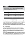
SubDrive Solar
Installation Manual
SOLAR SUBMERSIBLE
PUMP CONTROLLER
PUMP CONTROLLER
SOLAR SUBMERSIBLE
2
SUBDRIVE SOLAR INSTALLATION MANUAL TABLE OF CONTENTS
Overview....................................................................................................................................................... 5
Descriptions and Features........................................................................................................................... 5
How it Works................................................................................................................................................ 6
Features........................................................................................................................................................ 8
Installation.................................................................................................................................................. 12
Controller Location Selection.................................................................................................................... 13
Mounting Procedure.................................................................................................................................. 14
Wiring Connections................................................................................................................................... 14
Gland Plate Terminal Location Template.................................................................................................. 15
DC Wiring Connections.............................................................................................................................. 16
AC Wiring Connections (Optional)........................................................................................................... 17
Flow Switch Wiring Connections.............................................................................................................. 17
Flow Switch Installation and Operation................................................................................................... 18
Pump/Motor Wiring Connections............................................................................................................. 19
Run Control Switch Wiring Connections (Optional)................................................................................ 19
Control Switch Operation.......................................................................................................................... 20
Start-Up and Operation............................................................................................................................. 21
User Definable Parameters........................................................................................................................ 22
Generator Sizing for SubDrive Solar......................................................................................................... 24
Generator Selection Information.............................................................................................................. 24
Three-Phase Motor Specifications............................................................................................................. 25
Fault Codes and Troubleshooting............................................................................................................. 26
SubDrive Solar Specifications.................................................................................................................... 29
Solar Array Specifications.......................................................................................................................... 30
Solar Panel Wiring Configurations........................................................................................................... 31
SubDrive Solar Dimensions........................................................................................................................ 33
SubDrive Solar Mounting Dimensions...................................................................................................... 34
Addendum: Registry Values for RS485 Port Connection......................................................................... 35
3
ATTENTION
IMPORTANT INFORMATION FOR INSTALLERS OF THIS EQUIPMENT!
THIS EQUIPMENT IS INTENDED FOR INSTALLATION BY TECHNICALLY QUALIFIED PERSONNEL.
FAILURE TO INSTALL IT IN COMPLIANCE WITH NATIONAL AND LOCAL ELECTRICAL CODES,
AND WITHIN FRANKLIN ELECTRIC RECOMMENDATIONS, MAY RESULT IN ELECTRICAL
SHOCK OR FIRE HAZARD, UNSATISFACTORY PERFORMANCE, AND EQUIPMENT FAILURE.
FRANKLIN INSTALLATION INFORMATION IS AVAILABLE FROM PUMP MANUFACTURERS AND
DISTRIBUTORS, AND DIRECTLY FROM FRANKLIN ELECTRIC.
! WARNING
s
SERIOUS OR FATAL ELECTRICAL SHOCK MAY RESULT FROM FAILURE TO CONNECT THE MOTOR,
CONTROL ENCLOSURES, METAL PLUMBING, AND ALL OTHER METAL NEAR THE MOTOR OR
CABLE TO A PROPER EARTH GROUND IN ACCORDANCE WITH LOCAL CODES, USING WIRE NO
SMALLER THAN MOTOR CABLE WIRES. TO REDUCE RISK OF ELECTRICAL SHOCK, DISCONNECT
POWER BEFORE WORKING ON OR AROUND THE WATER SYSTEM. DO NOT USE MOTOR IN
SWIMMING AREAS.
! CAUTION
s
Use the SubDrive Solar controller only with Franklin Electric 4-inch submersible motors as
specified in this manual (see Table 6, pg. 28). Use of this unit with any other Franklin
Electric motor or with motors from other manufacturers may result in damage to both
motor and electronics.
! WARNING
s
High voltages (both AC and DC) capable of causing severe injury or death by electrical shock
are present in this unit. More than one disconnect switch may be required to de-energize
the equipment before servicing. This unit should only be installed or serviced by technically
qualified professionals.
Anytime working on or near the SubDrive Solar controller, or system:
• Securely cover the solar array with an opaque tarp.
• Turn OFF the external DC rated disconnect from the solar array to the SubDrive
Solar controller.
• Ensure AC power has been disconnected from the SubDrive Solar controller (if used).
• Wait a minimum of 5 minutes after removing power from the SubDrive Solar
controller before servicing.
! WARNING
s
Solar panels that have been exposed to full solar insolation for an extended period of time
can achieve high temperatures and could be a potential source of burns to exposed skin if
contacted. Use caution when working around solar arrays.
4
Overview
The SubDrive Solar controller is a variable speed motor drive designed to run a Franklin Electric
three-phase submersible induction motor. The SubDrive Solar provides water to remote locations by
converting high voltage, direct current from a solar array into alternating current to run a standard AC
submersible motor. When solar power is not available, the controller can automatically switch to an
alternate single-phase AC input such as a generator or inverter from battery, if available. The controller
provides fault detection, motor soft start, and speed control. The SubDrive Solar is designed to provide
these features with the plug and play ease of installation similar to a single-phase control box.
The SubDrive Solar is designed with the high standard of reliability expected of Franklin Electric
products. The controller attempts to drive the pump and motor to deliver water even under adverse
conditions, reducing output as necessary to protect the system components from damage, and only
shutting down in extreme cases. Full operation is restored automatically whenever abnormal
conditions subside.
Inspection
Before you begin, receive and inspect the SubDrive Solar unit. Verify that the part number is correct
and that no damage has occurred during transit.
Descriptions and Features
The SubDrive Solar system controller is based on a standard SubDrive platform controlling a Franklin
Electric 4-inch three-phase motor driving a 4-inch submersible centrifugal pump powered by a DC solar
array or an optional AC generator back-up.
The SubDrive Solar controller continuously monitors system performance and incorporates a number
of features for pump system protection. In the event of a fault, the SubDrive Solar will indicate the
type of fault through the three seven segment displays.
The SubDrive Solar system is optimized for pumping under adverse input power conditions
unique to solar arrays.
• Internal diagnostics will tolerate a lower input voltage.
• Whenever possible, the controller attempts to regulate the pump load in a manner that optimizes
for maximum power transfer from the solar array.
• The drive automatically switches to AC back-up power (when available) if the DC primary source is
unable to support pump operation.
The controller construction is ruggedized for hostile environmental conditions.
• The case is constructed of heavy-gauge zinc plated steel to resist rain, animal intrusion and
prolonged direct exposure to sunlight.
• The seals are designed for NEMA 3 (IEC rating IP55), (dust tight, withstands directed jets of water).
• For maximum protection against dust, there is no external cooling fan or other external
moving parts.
An easy to use interface is provided to enhance configurability and enable remote
system monitoring.
• A three-digit seven-segment display provides a detailed indication of system status.
• A small keypad offers flexibility for selection of user options.
• A continuous data connection for remote telemetry is made available via an RS-485 port.
• If using remote telemetry, follow the register information found in the RS-485 addendum.
5
Protection Features
Electronic monitoring gives the controller the capability to monitor the system and automatically shut
down in the event of:
• Dry well conditions – with smart pump monitoring
• Bound pump – with auto-reversing torque
• High Voltage Surge
• Low Input Voltage
• Open motor circuit
• Short circuit
• Over heat
• Dead-head/no flow conditions
NOTE: This drive provides motor overload protection by preventing motor current from exceeding
SFA and by limiting the duty cycle in the event of no water flow. This drive does not provide over
temperature sensing of the motor.
How it Works
The SubDrive Solar system serves to provide water in remote applications where electrical grid power
is either unreliable or unavailable. The system pumps water using a high-voltage DC power source
such as an array of solar panels. Since the sun is only available during certain hours of the day and
only in good weather conditions, the water is generally pumped into a storage tank. Two level
switches can be installed inside the tank to regulate the water level. A flow switch detects if flow is
below critical levels while the pump is still running. This serves as an indication that the well has run
dry, or that insufficient power is available to continue pumping. The system will shut down to protect
the pump and motor until the well, or adequate electric power, has recovered.
The SubDrive Solar controller runs at variable speed to match the changing power available from
the PV solar array. Variable speed operation means there is no in-rush or surge of energy during the
pump/motor start-up, helping to eliminate wear on the motor and pumping system. A leading cause
of pump motor failure is the stress applied to the motor during a full voltage start-up. The SubDrive
Solar variable speed operation ramps up the speed smoothly, which eliminates starting stress. This
feature enhances long-term motor reliability (pg 8).
6
The Franklin Electric SubDrive Solar is designed to be part of a system that consists of:
A. Solar Pump and Motor
B. SubDrive Solar Controller
C. Solar Array (not included)
D. Flow Switch (with sensor cable)
E. Control Switches (optional, not included)
F. AC Generator (optional, not included)
G. DC Rated Disconnect - Per applicable codes
H. Line Reactor (not included)
B
C
Figure 1: SubDrive
Solar System
SubDrive Solar
Controller
COMM.
COMM.
STATUS
UP
MENU
SELECT
DOWN
225979101,0
225996101,0
4-20mA
+5V
ANALOG
B-
A+
RS-485
0-5VDC
4-20mA
IN
OUT
SOLAR
SUBMERSIBLE
PUMP CONTROLLER
DC Polarity
Green = OK
Red = Reversed
E1 E2 E3 E4 E5 E6 E7 E8
Display
Status
Run
Mode
Idle
Mode
Motor
Underloaded
Under
Voltage
Running
Suitable for use on a circuit capable of delivering not
more than 5000 rms symmetrical amperes, 250V
maximum. Use 90 ºC CU wire rate 300V min.
COM
Locked
Pump
External
Trip
Open
Circuit
Short
Circuit
Overheated
Controller
Internal
Error
Flow Switch
Power On
D
Tighten line terminals to 15 in-lbs.
NC
NO
+ SOLAR PRIMARY
DC
L1
L2
BACKUP
AC
RUN
STOP TRIP
BLK RED YEL
MOTOR
Programming Header
DC Power
Solar PV Array
A
30A - 2 Pole DC
Rated Disconnect
F
Level
Control
“Stop”
(OPEN)
Pump/Motor
G
(CLOSED)
Level
Control
“Run”
E
(OPEN)
(CLOSED)
Alternate AC
Power (Optional)
H
2 Level Control Switch Operation
Pump Check Valve Requirements
NOTICE
In order to ensure maximum system reliability and water delivery, check valves must be installed
in the drop pipe. The first check valve must be installed at the pump (the 18-70 LPM [5-25 USGPM]
pumps have a built in check valve in the pump discharge) and additional check valves should be
installed every 30m (100 ft) of vertical pipe after the pump. See the pump owner’s manual for
additional information.
7
Features
System Diagnostics
The SubDrive Solar controller continuously monitors system performance and can detect a variety
of abnormal conditions. In many cases, the controller will compensate as needed to maintain
continuous system operation; however, if there is high risk of equipment damage, the controller
will protect the system and display the fault condition. If possible, the controller will try to restart
itself when the fault condition subsides. See Troubleshooting section for a list of Fault Codes and
corrective actions.
Motor Soft-Start
Normally, when there is a demand for water and power is available, the SubDrive Solar will be
operating. Whenever the SubDrive Solar detects a need for water, the controller always “ramps
up” the motor speed through a gradual increase of motor voltage, resulting in a cooler motor and
lower start-up current compared to conventional water systems. In cases where the demand for
water is low, the system may cycle on and off. Due to the controller’s soft-start feature this will not
harm the motor.
Over Temperature Foldback
The SubDrive Solar controller is designed for full power operation from a DC solar array in ambient
temperatures up to 122 °F (50 °C). Under extreme thermal conditions, the controller will reduce
output power in an attempt to avoid shutdown. Full pump output is restored when the controller
temperature cools to a safe level.
Pressure or Level Control Switch
A pressure or level control switch can be wired into the SubDrive Solar controller for water level
or pressure control. This is optional and is not required to run the SubDrive Solar controller. The
controller can be used with none, one, or two control switches. This provides the user maximum
adjustability when using the SubDrive Solar controller. See INSTALLATION section for more
information on installing and using control switches.
Automatically Switching to Back-up AC Power
The SubDrive Solar controller includes a secondary input power terminal that may be used
with a back-up 230 V AC power source. If there is sufficient voltage measured from the primary
source (Solar Array), the drive will attempt to draw from it to run the pump. The controller will
automatically switch to the alternate backup supply input if:
1. The PV (Photovoltaic) Solar Array input cannot provide sufficient Vdc after a number of attempts to successfully start the motor; AND
2. Generator back-up power is available at the AC back-up terminals.
8
When the system is running on back-up AC power, the drive will shut down for a few seconds
every 30 minutes to check the primary DC input terminals for sufficient power. If the primary DC
power is available, it will switch sources and attempt to run on DC. If the primary power is still
insufficient during this check, it will resume running on back-up AC power.
Call For Generator Dry Contacts
The SubDrive Solar controller has a set of dry contacts that can be used as a “Call for Generator”
function. There are three flag terminals inside the controller, two of which must be used.
NO – normally open; NC – normally closed (choose NO or NC based upon switch being used
or common state desired) and COM which is the common. These flag terminals are located in
between the AC terminal connections and the RUN/STOP/TRIP terminal connections.
When the drive no longer has adequate DC power it will then look for power at the AC terminal
block. At the same time, the state of those contacts changes (one will open, the other will close
based upon which contact terminal is used). This can then be read by an external switch. This is
not a powered contact, it only either opens or closes a circuit. In order to recognize this change
a switch controller with an independent power source must be utilized (for example an external
battery that can be charged once a generator is turned on).
Shown below is the state of each of the dry contacts (NO, NC) in the two operating modes. Adequate DC Power
NO = Closed
NC = Open
Inadequate DC Power
NO = Open
NC = Closed
To start a back-up AC generator through a closed circuit, use the NC (Normally Closed) and the
COM (Common) dry contact flag terminals.
9
Underload Smart Reset
Dynamic (Factory Setting)
If a motor underload fault condition occurs, the most likely cause is an over pumped or dry well.
The underload trip level is defined as a percentage of rated load at rated speed, the default
being 50%, which can be adjusted via the COMM Board user interface. Once tripped, the
timeout applied before a restart attempt varies according to the Dynamic Smart Reset schedule.
The intent is to adjust the “Off Time” as a function of the level of water in the well using
the formula: Off Time = Rule Time – Run Time. (Figure 2)
Off Time (Minutes)
1
2
3
Run Time (Minutes)
Figure 2: Dynamic Reset Model
Off Time (Minutes)
6
For wells having a slower recovery
rate, an extendable Rule Time that adjusts automatically is used.
The Rule Time is initially set to 5 minutes when the drive is first activated. However, if after restarting
5 quickly trips again (arrow 1), the Rule Time is extended. This process
from an underload, the drive
continues until the Rule Time grows long enough to keep the Off Time near the center range (arrow
2), up to a maximum of 80 minutes.
If later on the well begins to recover more quickly, the system
4
runs longer between trips and the Rule Time is gradually reduced in 5 minute increments (arrow 3).
This adaptive process allows3 for seasonal changes in well behavior.
2
1
0
0
1
2
3
4
5
6
Run Time (Minutes)
10
7
8
Fixed
Off Time (Minutes)
1
2
The SubDrive Solar controller can be set to a fixed “Off Time” rule via the COMM Board user
interface. It is factory preset to a fixed time of 53 minutes. In this mode, the controller will wait 30
seconds to 5 minutes, determined by duration of the previous run time, before restarting the motor.
For example, the first time the fault occurs, the controller will wait 30 seconds before attempting to
Run
Time
(Minutes)
restart the pump. If the system would then
run
for one
minute and an underload fault recurs, the
controller will wait four minutes before attempting to restart the pump. This schedule allows for the
minimum off-time possible based on the recovery time of the well. The fixed “Off Time” can be set
from five to 80 minutes in five minute increments. NOTE: The fixed “Off Time” will only take effect if
Parameter 3 is set to 1 = Fixed. (Figure 3)
Off Time (Minutes)
6
5
4
3
2
1
0
0
1
2
3
4
5
6
7
8
Run Time (Minutes)
Figure 3: Fixed Reset Model
Flow Switch
A flow switch comes with the SubDrive Solar package to detect low flow or no flow conditions and
prevent damage to the pump, motor, and plumbing. At times of limited sunlight, a point will be
reached where there is not enough solar power available to provide adequate flow. The pump will
reach a deadhead condition meaning the pump is spinning, but no water is moving. Continuous
operation in a deadhead condition may overheat the pump, motor, and subsequently the plumbing,
since no moving water carries away the heat. This flow switch overrides the “RUN” command from
any other control switches.
The flow switch detects adequate flow, permitting continuous operation; or detects zero or low
flow, enabling a “deadhead” operation mode which alternates a run-time interval and a cool-down
interval, to avoid overheating the motor and pump (See pages 17 & 18 for more information on
Flow Switch Operation). After a certain run time duration, if the flow switch does not detect flow it
will present an E4 fault code. The durations of the run-time and cool-down intervals depend on the
power being supplied by the controller: the more power going to the motor, the shorter the ontime and longer the cool-down. The controller will operate indefinitely in “deadhead mode”, until
available power either increases sufficiently to move adequate water or it decreases sufficiently that
the controller is no longer able to spin the motor. The SubDrive Solar controller will not operate with
the flow switch bypassed or jumpered. The controller is required to see “no flow” before attempting
to start the motor or a fault will occur.
11
Installation
! WARNING
s
High voltages (both AC and DC) capable of causing severe injury or death by electrical shock are
present in this unit. This unit should only be installed or serviced by technically qualified professionals.
Anytime working on or near the SubDrive Solar controller, or system:
• Securely cover the solar array with an opaque tarp.
• Turn OFF the external DC rated disconnect from the solar array to the SubDrive Solar controller.
• Ensure AC power has been disconnected from the SubDrive Solar controller (if used).
• Wait a minimum of five minutes after removing power from the SubDrive Solar controller before servicing.
READ THESE INSTRUCTIONS COMPLETELY BEFORE INSTALLATION.
Note: During installation, if a conflict arises between this manual and local or national electrical
codes, the applicable local or national electrical codes should prevail.
• The longevity and performance of the SubDrive Solar package may be adversely affected by
improper installation
• The solar PV array structure, modules, and wiring harness must be properly assembled according
to the manufacturer’s installation instructions before installing the SubDrive Solar controller.
• Wiring Requirements: Use 75 °C rated wire sized for a maximum voltage drop of 3% per local
electric codes.
Installation Preparation and Requirements
When installing the SubDrive Solar controller, be aware that:
• High voltage is present in the SubDrive when powered on; use caution when live DC power is on.
• Do not allow any unauthorized persons near the solar array and connection sites while
power is applied.
• It is strongly recommended that a DC rated disconnect box be used to disconnect the incoming DC
power from the SubDrive Solar controller during installation and maintenance. Use a Volt Meter
to confirm the absence of voltage in the line before proceeding with installation or maintenance.
• The DC disconnect should be sized to be capable of adequately disconnecting the output open
circuit voltage (Voc) and short circuit current (Isc) of the solar array.
• Keep all flammable materials away from the assembly site, including dry brush and vegetation.
• For optimal performance, avoid placing the PV solar array around any objects that can cast
shadows or reduce sunlight to the array.
• Install the SubDrive Solar controller out of direct sunlight to prevent overheating and reduced
performance. The optimum location is on the mounting pole for the PV Solar Array underneath
the array for protection from the sun, heat, and weather elements.
• Keep the surrounding area clear of vegetation.
• Do not block airflow around the SubDrive Solar controller heat sink.
• Limit access of animals to the system.
• Protect wires from damage from wildlife and weathering by using conduit. For additional
protection, bury the conduit in the ground.
12
Controller Location Selection
The SubDrive Solar controller is intended for operation in ambient temperatures up to 122 °F
(50 °C). The following recommendations will help in the selection of the proper location for the
SubDrive Solar controller (Figure 4):
CAUTION: When using an alternate AC power source, the ambient temperature is limited to 104 °F
(40 °C) for full power delivery.
1. The unit should be mounted on a sturdy supporting structure such as a wall or supporting post
Please take into account the weight of the unit.
2. The electronics inside the SubDrive Solar are air-cooled. As a result, there should be at least
45.7 cm (18 inches) both above and below to allow for air flow and proper cooling. If the
SubDrive Solar is mounted under the PV solar array, make sure that it is at least 45.7 cm (18 inches) beneath the array.
3. The SubDrive Solar should be mounted with the wiring end oriented downward. The
controller should not be placed in direct sunlight. Placing the controller in direct sunlight or high ambient temperatures could result in reduced performance due to temperature foldback protection. For optimum performance, maximize the shading of the controller.
Additional Considerations for NEMA 3 (IP55) Enclosures
To ensure maximum weather protection, the unit must be mounted vertically with the cover properly
aligned and secured with all lid screws. Strain relief fittings, or IP55 rated liquid tight conduit fittings,
should be used to bring the wires inside the enclosure.
Minimum
18 in/45.7 cm
Minimum
18 in/45.7 cm
Heat Sink
Figure 4: Controller Location
13
Mounting Procedure
1. Disconnect all electrical power supply.
2. Install the unit to a secure post using 1/4” (6 mm or M6) mounting screws (not included).
The top mounting holes are slotted in order to hang the drive in place, while the bottom
fasteners are inserted to secure the unit from ever sliding up.
3. If the mounting surface is narrower than the outer mounting slots, use the top center
and bottom center mounting holes and secure using 3/8” (8 mm or M8) mounting screws
(not included).
Wiring Connections
! WARNING
s
Serious or fatal electrical shock may result from failure to connect the ground terminal to
the motor, the SubDrive Solar controller, metal plumbing and all other metal near the motor,
or cable to a proper earth ground in accordance with local codes, using wire no smaller than
motor cable wires. To minimize risk of electrical shock, disconnect power before working on
or around the SubDrive Solar system. Do not use motor in swimming areas.
CAPACITORS INSIDE THE SUBDRIVE SOLAR CONTROLLER CAN STILL HOLD LETHAL VOLTAGE
EVEN AFTER POWER HAS BEEN DISCONNECTED. ALLOW FIVE MINUTES FOR DANGEROUS
INTERNAL VOLTAGE TO DISCHARGE BEFORE REMOVING SUBDRIVE SOLAR COVER.
The SubDrive Solar controller is not protected against a “bolted” short to ground at the motor
cable terminals. Ensure that the motor leads have been checked for a possible short to ground
BEFORE operating the drive.
1. Verify that the power has been shut off.
2. Remove the SubDrive Solar lid.
3. Remove the bottom gland plate from the SubDrive Solar enclosure and drill or punch the
necessary sized holes for the appropriate cord grips or conduit fittings to feed through.
(Do not attempt to drill holes with the gland plate on the enclosure. Damage could occur
to internal electronics, or metal shavings could short out electronics inside the drive).
4. Use appropriate strain relief or conduit connectors. For NEMA 3 (IP 55), Type B liquid-tight
fittings are recommended for maximum weather protection.
5. Make the appropriate wiring connections in the following instructions and install per all
applicable local and national codes.
a. Select wire gauge based on code recommendations for the maximum operating currents
listed in Table 7, page 29. Verify that any protection devices, such as fuses or circuit
breakers, are appropriately sized and installed per local and national code.
6. Replace the gland plate on the bottom of the enclosure. Do not over-tighten the screws.
a. Torque screws to 1.7 N-m (15 in.-lbs.)
7. Replace the cover. Do not over-tighten the screws.
a.Torque screws to 1.7 N-m (15 in.-lbs.)
b.NOTE: DO NOT SHIFT, CUT, OR DAMAGE THE SEALS WHEN REPLACING THE GLAND
PLATE AND COVER. DOING SO WILL RESULT IN LACK OF WEATHER PROTECTION AND LOSS OF NEMA AND IP RATINGS.
NOTE: Ensure that the system is properly grounded. Improper grounding may result in the loss
of voltage surge protection and interference filtering.
14
Use the template as a guide
for locating where to drill
holes in the gland plate.
DC
AC
CONTROL
WARNING: Do not drill holes
that extend into the shaded
area. This will diminish
the seal integrity of the
enclosure.
MOTOR
Gland Plate Terminal Location Template
Gland plate seal
15
DC Wiring Connections
1. Make sure that the external disconnect switch is off.
2. Make sure that AC power is disconnected (if installed)
3. Make sure that all wires are properly identified and marked:
•the cable from the PV to the external DC disconnect switch
•the cable from the external DC disconnect to the SubDrive Solar controller
4. Connect the cables from the external DC disconnect to the terminal block labeled “Solar Primary DC” and marked +, - and GND. (Figure 5) (Torque specification: 15 in-lbs/ 1.7 N-m).
COMM.
COMM.
STATUS
MENU
UP
SELECT
DOWN
225979101,3
-
Figure 5: DC Wiring Connection
+
RS-485
225996101,2
Error Codes
E1 E2 E3 E4 E5 E6 E7 E8 E9
Display
Status
Run
Mode
Suitable for use on a photovoltaic circuit capable of delivering not more
than 50 DC amps short circuit current, or on a backup AC generator
capable of delivering not more than 5000 amps symmetrical RMS current.
See manual for allowed ratings of solar array (DC) and generator (AC).
Use 90 °C wire rated 600V min for DC and 300V min for AC.
Idle
Mode
Motor
Underloaded
Under
Voltage
Locked
Pump
Service
Diagnostic Aid
COM
Tighten terminals to 7 in-lbs.
SOLAR PRIMARY
Tighten terminals to 15 in-lbs.
Open
Circuit
Short
Circuit
Overheated
Controller Reserved
Internal
Error
Tighten terminals to 15 in-lbs.
NC
NO
+ -
L1
L2
(GND)
SOLAR PRIMARY
DC
BLK RED YEL
(GND)
BACKUP
AC
Multiple electrical power sources may be connected.
Disconnect all electrical power before servicing.
RUN
STOP TRIP
(GRY)
(BLK)
(BRN) (GND)
MOTOR
Programming Header
+ -
External
Trip
WARNING – Operation of this equipment requires
detailed installation and operation instructions provided
in the Installation/Operation manual intended for use
with this product. Additional copies of the
Installation/Operation manual may be ordered by
contacting your local Franklin Electric representative.
DC
CAUTION
Only connect a photovoltaic solar array to the DC input of the SubDrive Solar controller. This
controller is suitable for use on a PV circuit capable of delivering not more than 50 DC amps short
circuit current.
In this drive, the integral solid state short circuit protection of motor wiring does not provide circuit
protection of wiring for input power. Input wiring protection must be provided in accordance
with all applicable national and local electrical codes. In addition, follow any manufacturer’s
recommendations for protection of a photovoltaic (PV) array and protection of a generator, if used.
16
AC Wiring Connections (Optional)
The SubDrive Solar Controller has AC wiring connections for use with a generator when Solar DC
power is not available.
1. Make sure the generator is powered off.
2. Make sure the external DC disconnect switch is off.
3. Connect the cables from the generator to the Terminal Block labeled “Back-up AC” and marked
L1, L2, and GND. (Figure 6) (Torque specification: 15 in-lbs/ 1.7 N-m).
COMM.
COMM.
STATUS
MENU
SELECT
UP
DOWN
225979101,3
-
+
RS-485
225996101,2
Error Codes
E1 E2 E3 E4 E5 E6 E7 E8 E9
Display
Status
Run
Mode
Idle
Mode
Suitable for use on a photovoltaic circuit capable of delivering not more
than 50 DC amps short circuit current, or on a backup AC generator
capable of delivering not more than 5000 amps symmetrical RMS current.
See manual for allowed ratings of solar array (DC) and generator (AC).
Use 90 °C wire rated 600V min for DC and 300V min for AC.
Motor
Underloaded
Under
Voltage
Locked
Pump
External
Trip
Diagnostic Aid
COM
Tighten terminals to 7 in-lbs.
Tighten terminals to 15 in-lbs.
Open
Circuit
Short
Circuit
Overheated
Controller Reserved
Internal
Error
WARNING – Operation of this equipment requires
detailed installation and operation instructions provided
in the Installation/Operation manual intended for use
with this product. Additional copies of the
Installation/Operation manual may be ordered by
contacting your local Franklin Electric representative.
Service
Figure 6: AC Wiring Connection
Tighten terminals to 15 in-lbs.
NC
NO
L2
+ -
L1
L2
(GND)
BLK RED YEL
(GND)
SOLAR PRIMARY
RUN
STOP TRIP
(GRY)
(BLK)
(BRN) (GND)
MOTOR
BACKUP
DC
BACKUP
AC
Programming Header
L1
Multiple electrical power sources may be connected.
Disconnect all electrical power before servicing.
AC
Flow Switch Wiring Connections
The SubDrive Solar Controller makes use of a flow switch to protect the controller and motor when
there is not enough power to generate proper flow. The flow switch and sensor cable is included with
the SubDrive Solar QuickPAK and is required on all installations.
1.Connect the cables from the Flow Switch terminals NO and COM, and to the SubDrive Solar
terminal block labeled “TRIP” (Figure 7).
COMM.
COMM.
STATUS
MENU
UP
SELECT
DOWN
Figure 7: Flow Switch Wiring Connection
225979101,3
-
+
RS-485
225996101,2
Error Codes
E1 E2 E3 E4 E5 E6 E7 E8 E9
Display
Status
Run
Mode
Suitable for use on a photovoltaic circuit capable of delivering not more
than 50 DC amps short circuit current, or on a backup AC generator
capable of delivering not more than 5000 amps symmetrical RMS current.
See manual for allowed ratings of solar array (DC) and generator (AC).
Use 90 °C wire rated 600V min for DC and 300V min for AC.
Idle
Mode
Motor
Underloaded
Under
Voltage
Locked
Pump
Service
Diagnostic Aid
COM
Tighten terminals to 7 in-lbs.
Tighten terminals to 15 in-lbs.
External
Trip
Open
Circuit
Short
Circuit
Overheated
Controller Reserved
Internal
Error
WARNING – Operation of this equipment requires
detailed installation and operation instructions provided
in the Installation/Operation manual intended for use
with this product. Additional copies of the
Installation/Operation manual may be ordered by
contacting your local Franklin Electric representative.
Tighten terminals to 15 in-lbs.
NC
NO
L1
L2
(GND)
DC
BLK RED YEL
(GND)
BACKUP
AC
Multiple electrical power sources may be connected.
Disconnect all electrical power before servicing.
RUN
STOP TRIP
(GRY)
(BLK)
(BRN) (GND)
MOTOR
Programming Header
+ SOLAR PRIMARY
TRIP
CAUTION
Failure to properly install the included flow switch will result in reduced system performance and may
result in system damage.
17
Flow Switch Plumbing Installation
! WARNING
s
Hazardous Pressure Present: Pressure at the flow switch must be limited according to the water
temperature that the flow switch will see in service. Note that this includes the temperature
that the water could reach due to heating by the surrounding environment. Pressure at the
flow switch must be limited according to the following table.
Flow Switch Pressure Rating vs. Water Temperature
Maximum Water Temperature (°C)
Gauge Pressure (bar)
Gauge Pressure (psi)
20
18
261
25
15.75
228
30
13.5
196
35
11.25
163
40
9
131
45
6.75
98
50
4.5
65
55
2.25
33
60
0
0
Table 1: Flow Switch Pressure
NOTE: Pressure at the flow switch can be reduced by eliminating plumbing restrictions including
reductions in pipe diameter downstream of the flow switch.
On the F21 paddle style flow switch, the paddle must be trimmed to allow it to fit into the plumbing.
The paddle should be trimmed so that it is as long as possible, but not closer than 4 mm (.160”), to the
pipe walls when installed. A longer paddle length will increase flow switch sensitivity and therefore
water delivery at low power conditions. Additional installation instructions including mounting
orientation, paddle trimming, other plumbing requirements, etc. are included with the flow switch.
Follow the installation instructions included with the packaging of the flow switch for installation and
maintenance information.
Flow Switch Operation
At start-up, the flow switch naturally detects no flow. If the flow switch detects flow before the
controller starts the motor, then the flow switch wiring is faulty or the paddle is stuck and the
controller stops, displaying an E4 error. The state of the switch must show no flow in order for the
drive to attempt to start. After the controller starts the motor, it expects the flow switch to detect
flow within an interval that depends on power being delivered. If the flow switch detects flow within
that interval, then the controller operates normally. If the flow switch does not detect flow, the
controller enters a deadhead mode, displaying E4, and alternately runs the motor and pump, then
allows them to cool.
The time intervals during deadhead mode depend on the power being provided by the controller. For
power less than 1200 Watts, the overall repeat time interval is approximately 11 minutes. For power
greater than 1200 Watts, the repeat time interval is approximately 14 minutes. The run-time and cooldown portions within each repeat time interval are controlled to limit the total energy supplied to
the motor/pump within each interval, and are thus dependent on the controller output power.
18
Pump/Motor Wiring Connections
1. Connect the cables from the Pump/Motor Assembly to the Terminal Block labeled “MOTOR” and marked BLK, RED, YEL, and GND (Figure 8). (Torque specification: 15 in-lbs/ 1.7 N-m).
2. Motors with international leads use Table 2 for motor lead color information to ensure correct installation.
US
Black (BLK)
Red (RED)
Yellow (YEL)
Ground (GND)
International
Gray (GRY)
Black (BLK)
Brown (BRN)
Ground (GND)
Table 2: US and International Wire Color Chart
COMM.
COMM.
STATUS
MENU
UP
SELECT
DOWN
225979101,3
-
+
RS-485
225996101,2
Error Codes
E1 E2 E3 E4 E5 E6 E7 E8 E9
Display
Status
Run
Mode
Idle
Mode
Motor
Underloaded
Under
Voltage
Locked
Pump
External
Trip
Open
Circuit
Short
Circuit
Overheated
Controller Reserved
Figure 8: Motor Wiring Connection
Internal
Error
WARNING – Operation of this equipment requires
Suitable for use on a photovoltaic circuit capable of delivering not more
than 50 DC amps short circuit current, or on a backup AC generator
Service
capable of delivering not more than 5000 amps symmetrical RMS current.
See manual for allowed ratings of solar array (DC) and generator (AC).
Use 90 °C wire rated 600V min for DC and 300V min for AC.
Diagnostic Aid
COM
Tighten terminals to 7 in-lbs.
Tighten terminals to 15 in-lbs.
detailed installation and operation instructions provided
in the Installation/Operation manual intended for use
with this product. Additional copies of the
Installation/Operation manual may be ordered by
contacting your local Franklin Electric representative.
Tighten terminals to 15 in-lbs.
NC
NO
(GRY)
(BLK)
(BRN) (GND)
+ -
L1
L2
(GND)
SOLAR PRIMARY
DC
BLK RED YEL
(GND)
BACKUP
AC
RUN
STOP TRIP
(GRY)
(BLK)
(BRN) (GND)
MOTOR
Multiple electrical power sources may be connected.
Disconnect all electrical power before servicing.
Programming Header
BLK RED YEL
CAUTION
For retrofit application, make sure to check integrity of power and motor leads. This requires
measuring the insulation resistance with the suitable megohmmeter. Reference the Franklin Electric
AIM for correct measures. (See Table 4. Motor Specifications, pg. 25)
Control Switch
Wiring Connections (Optional)
The SubDrive Solar Controller can be operated with control switches to control the ON/OFF
pumping range. Use a normally closed low-voltage control switch with a contact rating suitable for
instrumentation use (i.e. Max: 24 V 15mA)
1. Connect the cables from the “STOP” control switch to the Terminal Block labeled “STOP”.
2. Connect the cables from the “RUN” control switch to the Terminal Block labeled “RUN” (Figure 9).
19
COMM.
COMM.
STATUS
MENU
UP
SELECT
Figure 9: Control Switch
Wiring Connection
DOWN
225979101,3
-
+
RS-485
225996101,2
Error Codes
E1 E2 E3 E4 E5 E6 E7 E8 E9
Display
Status
Run
Mode
Suitable for use on a photovoltaic circuit capable of delivering not more
than 50 DC amps short circuit current, or on a backup AC generator
Idle
Mode
Motor
Underloaded
Under
Voltage
Locked
Pump
Service
capable of delivering not more than 5000 amps symmetrical RMS current.
See manual for allowed ratings of solar array (DC) and generator (AC).
Use 90 °C wire rated 600V min for DC and 300V min for AC.
Diagnostic Aid
COM
Tighten terminals to 7 in-lbs.
Tighten terminals to 15 in-lbs.
External
Trip
Open
Circuit
Short
Circuit
Overheated
Controller Reserved
Internal
Error
WARNING – Operation of this equipment requires
detailed installation and operation instructions provided
in the Installation/Operation manual intended for use
with this product. Additional copies of the
Installation/Operation manual may be ordered by
contacting your local Franklin Electric representative.
Tighten terminals to 15 in-lbs.
NC
NO
L1
L2
(GND)
DC
BLK RED YEL
(GND)
RUN
BACKUP
AC
Multiple electrical power sources may be connected.
Disconnect all electrical power before servicing.
RUN
STOP TRIP
(GRY)
(BLK)
(BRN) (GND)
MOTOR
Programming Header
+ SOLAR PRIMARY
STOP
2 Control Switch Operation
The SubDrive Solar is designed to utilize up to two control switches for operation. When both
switches are installed, the controller starts to pump and waits to shut off until both switches
read “OPEN”. Once it shuts off, the controller then waits to run again until both switches read
“CLOSED”. An example application (Figure 10) is to use separate level switches to indicate high
and low water levels. Two pressure switches, one with a high pressure cut-out in the “STOP” input
terminal, and a second low pressure cut-in switch in the “RUN” input terminal can also be used
to manage the system in applications that do not have an open discharge. Parameter 1 should be
changed to “2” in the menu controls. SEE USER DEFINABLE PARAMETERS in operation section of
manual for instructions.
1 Control Switch Operation
Alternatively, the SubDrive Solar controller may be configured to control water level by using
a single input switch. Once properly configured for a single active input with a control switch
installed, the controller starts to pump and waits to shut off until the active switch reads “OPEN”.
Once it shuts off, the controller then waits to run again until the switch reads “CLOSED”. An
example application (Figure 10) would be to use a single-contact level-switch that keeps the
storage tank as full as possible without overflowing. A single pump control pressure switch can be
used to control the pressure range between an adjustable range (i.e. 30/50 psi pressure switch).
For single level switch control, use only the “RUN” terminal connections. Parameter 1 should be
changed to “1” in the menu controls. SEE USER DEFINABLE PARAMETERS in operation section of
manual for instructions.
0 Control Switch Operation
Lastly, the SubDrive Solar controller may be configured to not use a control switch. The SubDrive
Solar controller is default to parameter 1 setting of 0 control switch inputs. In this configuration
the SubDrive Solar will always try to run the motor and pump water as long as there is sufficient
power from the solar array or alternate AC power source.
20
Control
Switch-Stop
(OPEN)
(OPEN)
Control
Switch-Run
(CLOSED)
Pumping
Range
Pumping
Range
(CLOSED)
Control
Switch-Run
(OPEN)
(CLOSED)
2 Control Switch Operation
1 Control Switch Operation
Figure 10: Control Switch Operations
NOTE: All control switch configurations are superseded by the “Flow Switch”. If the flow switch
detects low flow it will “OPEN” and override the run signals sent by the control switches to protect
the motor and drive.
Start-Up and Operation
After all appropriate connections have been made, apply power to the controller. A steady green
light in the “Power/DC Polarity” location indicates that the SubDrive Solar controller has either AC
or DC power connected. A red light in the “Power/DC Polarity” location indicates that the positive
and negative connections have been reversed. The seven segment display will power on shortly after
power is applied to the controller. It will flash the current software version of the main controller,
then the software version of the COMM board processor, and finally to the normal operating display.
The display will show an E2 fault on the display if the polarity is reversed.
By default the seven segment display shows motor frequency during operation. The display can also show
the system power in kW, or a rotating segmented graphic signifying the pump/motor is running. These
different display modes can be cycled through using the up and down soft buttons. While running on DC power, approximately every eight minutes the system will shut down for a few seconds and then
restart. This is normal operation and is used to look at the system open circuit voltage to derive a max
power point.
While running on AC generator power, the drive will shut down approximately every 30 minutes for
a few seconds and restart. This is normal operation; the drive is just attempting to find adequate DC
power input. As soon as DC power becomes available, the system will then change over to the array
power. If DC power is not available or is not adequate, the system will continue to run on AC power.
CAUTION
The SubDrive Solar controller’s display is protected by a sliding metal shield. After reading the
display, ensure that the shield covers the display. Failure to do so could result in damage and will
result in yellowing of the view pane and can eventually render the display unreadable.
NOTE: For optimal operation results, it is recommended to flush the bore well system until the water
being discharged is clear and free of debris. This will reduce the chances of the flow switch being
clogged by sediment and debris during initial start-up.
21
User Definable Parameters
The following explains the menu structure and User Defineable Parameters that are effective on SubDrive Solar controllers with software versions 1.4.4 (COMM Board), 2.11 and 2.12 (main controller) and later versions.
Pressing the “Menu” button from the normal operating display enters the User Defineable
Parameters menu. Pressing the up and down arrows will cycle through the parameter list.
To enter a parameter, press the “Select” button on the desired parameter. The display shows
the last saved value. Use the “Up/Down” arrows to change the parameter to the desired
value. Confirm the selection by pressing the “Select” button.
The display will then alternately flash between the new selected value and the parameter
number three times and ultimately return to the normal operating display.
Factory default settings are shown as BOLD.
Description
Parameter
Factory Reset
rSt
Values
yes
no
2
# of Control Switch Inputs
P1
1
0
• Restores User Defineable Parameters to factory default settings
• Flashes “no” after “yes” is selected
• Indicates this value, as well as others, has been reset to factory default
• Sets number of control switches if used
• If only one switch is required it must go in the “Run” terminal
• Count should include only run/stop control switches, but not the flow switch
100
Underload Trip
Sensitivity (%)
P2
50
• Sets the underload trip sensetivity (%)
• Up/Down 30-100% by 1
30
Select Reset Rule Type
P3
Select Fixed Reset Rule Time
P4
Enable Minimum Off Time
P5
on
off
80
5
on
off
• Fixed Reset Rule ON
• Dynamic Reset Rule OFF Turns on/off fixed reset rule
• Only effects operation if P3 = ON
• Up/Down 5-80 by 5 minutes
• “on” selection enables user to select a minimum
• “off” time of the system
1
Select Minimum Off Time
Interval
P6
10
60
22
• Only effects operation if P5 = ON
• 1, 10-60 by 10 minutes
Figure 11 shows the layout of the user interface on the COMM Board. Using the soft buttons and
the seven segment display, the user defined parameters can be changed.
COMM.
COMM.
STATUS
MENU
UP
SELECT
DOWN
-
+
RS-485
225996101,2
Figure 11: COMM Board User Interface
NOTE: The COMM Board User Interface is the only piece in the SubDrive Solar controller that can be
touched while power is applied to the drive. The COMM board is low voltage and electrically isolated
from the high voltage portions of the drive.
! WARNING
s
Do NOT touch any other piece inside the SubDrive Solar controller while power is applied.
To service any other areas of the drive, disconnect ALL power sources and wait five minutes
before continuing.
Example process for changing Software Parameters:
Run Status
(kW)
Parameter
Number
MENU
DN (3X) SELECT
Value
Now
New
Value
Parameter
Number
SELECT
MENU
Run Status
(kW)
Display Reading:
UP (3X)
Button:
The previous example changes the fixed underload time-out setting from 50 minutes to 65 minutes
and demonstrates how to change any of the listed parameters.
23
Generator Sizing for SubDrive Solar
Table 3 lists minimum generator sizes based on typical 80 °C rise continuous duty generators,
for Franklin’s three-wire, single- or three-phase motors. This is a general chart. The generator
manufacturer should be consulted whenever possible, especially on larger sizes.
Follow generator manufacturer’s recommendations for de-rating at higher elevations or using
natural gas.
MOTOR RATING
HP
KW
0.75
MINIMUM RATING OF GENERATOR
EXTERNALLY REGULATED
KW
KVA
0.55
2.5
3.1
1.5
1.1
5
6.25
3
2.2
10
12.5
Table 3: Generator Sizing
Generator Selection Information
Not all AC generators will perform sufficiently with the SubDrive Solar product. Always
consult the generator manufacturer for application-specific information.
In a SubDrive Solar controller, AC input current flows directly through the input rectifier into
a storage capacitor, with no active power-factor-correction (PFC) circuitry. Because of variation
of generator performance when connected to an input circuit like this, it is recommended that
a suggested minimum kVA rating be obtained from the generator supplier for this type of
application (input rectifier to capacitor, no PFC).
The AC input of a SubDrive Solar controller draws current only near the peaks of the sinewave generator voltage. This pattern of current peaks may distort an input sine-wave voltage,
limiting the generator’s ability to maintain the voltage level required by the drive. This
behavior is typical for equipment without dedicated power-factor-correction circuits.
A generator’s ability to provide low-distortion voltage during such operation is limited
by a generator parameter called “sub-transient output reactance”. The lower the
sub-transient output reactance, the better the generator can maintain a low-distortion
sine wave output voltage.
Generators with the following ratings are expected to be capable of providing adequate
voltage to SUBDRIVE Solar drives at rated power of the drives.
For SubDrive Solar Model 5870300553: 3.1kVA, less than 25% sub-transient reactance
For SubDrive Solar Model 5870301113: 5.5 kVA, less than 25% sub-transient reactance
For SubDrive Solar Model 5870301223: 9 kVA, less than 20% sub-transient reactance
The above information is a guideline for selecting a generator based on best known practice.
Not all AC generators will perform satisfactorily with the SubDrive Solar product and can result
in, but not limited to, nuisance tripping, unsatisfactory performance, or drive damage. Always
consult the generator manufacturer for best-use practices.
24
Generator Line Reactor Specifications
A single-phase line reactor is recommended when using a back-up generator source, located
between a generator and the controller for both 1.1 kW and 2.2 kW units. Without a line
reactor, the drive can experience excessive heating and will reduce performance or stop to
protect itself.
• Minimum 0.4 mH inductance, rating of 25 ampere rms current, continuous, for 2.2 kW
• Minimum 0.4 mH inductance, rating of 15 ampere rms current, continuous, for 1.1 kW
• Minimum 0.4mH inductance, rating of 10 ampere rms current, continuous, for 0.55 kW
Line reactors are typically available as three-phase line reactors. Follow the manufacturer’s
instructions for use in single-phase application. The reactors can be mounted at the generator, using
the proper enclosure rating determined to be adequate for the generator.
Three-Phase Motor Specifications
MAXIMUM
LOAD
HP
KW
VOLTS
HZ
S.F.
AMPS
WATTS
AMPS
WATTS
LINE TO LINE
RESISTANCE
OHMS
2349029204
0.75
0.55
100
60
1.5
6.9
830
8.6
1185
1.1 – 1.4
N
2345049203
1.5
1.1
200
60
1.3
5.8
1460
6.8
1890
2.5 – 3.0
K
2343062604
3
2.2
200
60
1.15
10.9
2920
12.5
3360
1.3 – 1.7
K
MOTOR
MODEL
RATING
FULL LOAD
KVA
CODE
Table 4: Motor Specification Data
Maximum Motor Cable Length (in feet)
AWG Copper Wire Size, (75 °C Insulation)
Drive Model
Motor
HP
14
12
10
SD Solar 0.55KW N3
0.75
130
220
SD Solar 1.1KW N3
1.5
310
500
SD Solar 2.2KW N3
3.0
180
290
8
6
340
530
830
790
1000
470
740
4
1000
Maximum Motor Cable Length (in meters)
Square Millimeter Copper Wire Size, (75 °C Insulation)
Drive Model
Motor
KW
1.5
2.5
4
6
10
16
SD Solar 0.55KW N3
0.55
20
40
70
110
190
300
SD Solar 1.1KW N3
1.1
70
120
190
290
305
SD Solar 2.2KW N3
2.2
30
60
100
160
260
305
Table 5: Wire Sizing Charts
* Maximum cable length from the drive to the motor is 1000 ft (305 m). External filtering is required for motor
cable lengths exceeding this maximum distance or nuisance tripping might occur.
25
Motor Lead Installation
NOTE: The included motor in the SubDrive SolarPAK does come with a factory installed individual
conductor lead. To replace or install a new lead, please follow these steps:
1.Remove the plastic bag from the lead connector and spread the lubricant evenly around the
lead prong.
2.Align the orientation key on the lead connector with the slot in the motor end bell, and press
the lead connector firmly into the socket.
3.Start the jam nut into the connector threads, ensuring that the threads are properly engaged.
4.Using a 19 mm (3/4”) open ended wrench, tighten the jam nut until it is snug. Recommended
torque 20-27 N-m (15-20 lb-ft). DO NOT OVER TORQUE.
Fault Codes and Troubleshooting
The SubDrive Solar controller will attempt to operate the pump to deliver water even under adverse
conditions. To ensure years of reliable service, it must also protect the system components from
conditions that might result in equipment damage. When adverse conditions arise, the controller
will continue to deliver as much water as possible at a reduced output if necessary, and will
shut down only in extreme cases. Full operation will resume automatically whenever abnormal
conditions subside.
Error conditions may suspend certain features, reduce output, or shut down operation of the system
for varying amounts of time depending on the nature and severity of the error. Problems that
merely reduce features or performance generally restore full operation when the trouble condition
subsides without stopping the pump or flashing an error code. If an error requires stopping the
motor, a stop delay of at least 30 seconds will accompany the fault. The error code is shown on the
seven-segment display.
If the drive has stopped to indicate a fault code on the display, the associated time-out delay will vary
depending on the nature of the fault. The number following the “E” symbol corresponds to the error
code for the offending condition.
Undervoltage (E2)
The SubDrive Solar controller displays an E2 fault when the input voltage is at an unacceptable level.
However, measuring the input voltage may reveal a voltage well within the normal operating range,
yet the drive still displays the E2 fault. This is commonly due to the characteristics of the solar PV
array. Virtually any illumination (solar) intensity will result in the array producing full or near full open
circuit voltage when under no electrical load. However, with low illumination when the drive begins
to draw power to run the motor, the voltage on the array will fall quickly due to a lack of available
current from the PV array. The current capacity of the PV solar array is affected much more by solar
intensity than voltage. Once the current demand exceeds or nears the current available, the voltage
drops quickly along the flat portion of the amp - Volt (IV) curve (see example array curves on the
following page). This drop in voltage then causes an E2 fault condition and will stop the motor. After
approximately one minute, the drive will power up again to check if illumination is sufficient enough
to run the motor.
This cycling of E2 fault conditions is normal during the morning and evening hours and other times
of non-peak illumination. Measuring the open circuit voltage alone is not always a good indication of
the suitability of sufficient solar power since the voltage will change when the motor begins to run.
The SubDrive Solar controller will operate the motor in the widest possible range of power from the
PV array.
26
Example Solar PV Array Curves
Displaying Diminishing Solar Light Intensity
Current-Voltage and Power-Voltage curves for a PV array containing six generic 180 Watt
PV panels in series.
Each panel having the following values at standard test conditions (STC of 1000 W/m2,
25 deg C panel temp): Isc = 5.0 A, Voc = 50 Vdc, Imp = 4.6 A, Vmp = 40 Vdc
Curves calculated for five different light levels: 200 to 1000 W/m2 in 200 W/m2 steps, at
constant 25 deg. C panel temperature
Current - Voltage curves for PV array
Output current (amps)
6
5
4
3
2
1
0
0
100
200
300
Output voltage (volts)
1200
Power - Voltage curves for PV array
Output power (watts)
1050
900
750
600
450
300
150
00
100
200
300
Output voltage (volts)
27
Display Fault
Possible Causes
Corrective Action
E1
Motor Underload
Air-locked pump. Overpumped or
dry well. Worn pump, damaged
shaft or coupling, blocked pump or
pump screen.
Wait for well to recover and auto restart
to occur. (See description of Underload
Smart Reset). If the problem persists,
check pump and motor.
E2
Undervoltage
Misconnected or loose input leads.
Low sunlight to PV array.
Generator voltage too low.
Tighten any loose input connections.
Wait for more intense sunlight.
Follow generator troubleshooting
guide.
E3
Locked Pump
Motor/pump misaligned.
Pump bound up with sand or
abrasive.
Dragging motor or pump.
Unit will attempt to free a locked pump.
If it is unsuccessful, check the motor
and pump.
E4
External Trip
Water flow too low to adequately
cool pump and motor.
Flow switch miswired.
Check that “trip” terminal is correctly
wired to flow switch.
Check that flow switch is properly
installed in pipe discharge.
Check that pipe discharge is not blocked.
Wait for sufficient solar power to pump
adequate water.
E5
Open Circuit
Loose or open connection to motor.
Defective motor or cable
Check motor cable connections.
Cycle input power* to reset.
If problem persists, check cable and
motor.
E6
(a) At power-up: Short Circuit
(b) While running: Over Current
(a) short in motor connections at
terminal or within motor cable.
(b) debris in pump.
(a) check motor connections at terminal.
(b) Check pump.
Cycle input power* to reset.
If problem persists, check motor cable
and pump.
E7
Overheated Controller
Unit in direct sunlight.
High ambient temperature.
Obstruction of air flow.
Shade unit.
Clean any debris from heat sink fins on
rear of enclosure.
This fault automatically resets when
temperature returns to safe level.
E9
Internal Error
Controller internal processing has
encountered an incorrect value.
Cycle input power.*
Table 6: Fault Code / Troubleshooting
* “Cycle input power” means disconnecting PV and generator power (if used) for at least five
minutes, then re-connecting power.
28
SubDrive Solar Specifications
Absolute maximum input voltages
PV, DC
410 V, open circuit
Back-up generator
260 VAC, rms
NOTE: Suitable for use on a photovoltaic circuit capable of delivering not more than 50 DC amps
short circuit current, or on a backup AC generator capable of delivering not more than 5000
amps symmetrical rms current.
0.55 kW model*
1.1 kW model**
2.2 kW model**
5870300553
5870301113
5870301223
Output voltage, max
100 V AC, 3-phase
200 V AC, 3-phase
200 V AC, 3-phase
Max Amps (RMS)
8.6 A, each phase
6.8 A, each phase
12.5 A, each phase
Output Frequency
30-60 Hz
30-58 Hz
30-68 Hz
Efficiency at Max Power
96%
96%
96%
Controller Model No.
Output
PV source
Input Voltage, at mpp
95 – 330 V DC
190 – 330 V DC
190 – 330 V DC
Max Amps Input
8.7 A DC, continuous
7 A DC, continuous
12 A DC, continuous
Power at mpp
Up to 1400 watts
Up to 2000 watts
2000 – 3500 watts
230 V AC, single-phase
230 V AC, single-phase
230 V AC, single-phase
Alternate AC Generator
Input voltage
Max Amps (RMS)
9.7 A DC, continuous
16 A
25 A
Power and VA capability
Follow Instruction Manual
for proper Generator
Sizing Data
Follow Instruction Manual
for proper Generator
Sizing Data
Follow Instruction Manual
for proper Generator
Sizing Data
LXWXD
LXWXD
Centimeters
53.34 X 25.87 X 21.87 cm
53.34 X 25.87 X 21.87 cm
53.34 X 25.87 X 26.31 cm
Inches
21.00” X 10.19” X 8.61”
21.00” X 10.19” X 8.61”
21.00” X 10.19” X 10.36”
Temperature Range
-25 °C to 50 °C (40 °C max
when using AC generator)
-13 °F to 122 °F (104 °F max
when using AC generator)
-25 °C to 50 °C (40 °C max
when using AC generator)
-13 °F to 122 °F (104 °F max
when using AC generator)
-25 °C to 50 °C (40 °C max
when using AC generator)
-13 °F to 122 °F (104 °F max
when using AC generator)
Relative Humidity Range
0 to 100% Condensing
0 to 100% Condensing
0 to 100% Condensing
Controller Size
Operating Conditions
*The 0.55 kW drive will attempt to start the pump/motor with input voltage as low as 95 V, and attempt to continue to
run the pump/motor as low as 75 V input voltage. However, 75 Vdc should not be interpreted as an adequate rated PV
array output voltage for any installation. The recommended Vmpp minimum for the system’s solar PV array is 110 Vmpp.
Maximum open circuit voltage input to the controller is 410 Voc. See the PV Solar Array Specifications and System Sizing
program for indication of adequate array voltage to provide useful pumping capability.
**The 1.1 and 2.2 kW Drive will attempt to start the pump/motor at 190 V DC, and attempt to continue operation down to
150 V DC. The recommended Vmpp minimum for the system’s solar PV array is 225 Vmpp. Maximum open circuit voltage
input to the controller is 410 Voc.
Table 7: SubDrive Solar Drive Specifications
29
Electrical Diagram
Input Power
+
+
Solar Primary DC Contactor 1
Q1
D1
Q3
D3
Q5
D5
C1
AC
Motor
Backup
AC
L1
L2
+
Bridge
Rectifier
-
-
Q2
D2
Q4
D4
Q6
D6
Contactor 2
PV Solar Array Specifications
Absolute maximum array voltages
Vmpp = 330 Vdc
Voc = 410 Vdc
maximum operating voltage at max power point of PV source
maximum open-circuit voltage
Minimum array voltage at minimum array peak power
(provides max of 25% of rated system pumping power at STC)
System size
Minimum PV array voltage
Minimum PV array power
0.55 kW
95 Vdc
250 Wp
1.1 kW
190 Vdc
500 Wp
2.2 kW
190 Vdc
875 Wp
Array voltage and power for full system capability
(provides 100% of rated system pumping power at STC)
System size
Target PV array voltage
PV array power*
0.55 kW
150 Vdc
1400 Wp
1.1 kW
300 Vdc
2000 Wp
2.2 kW
300 Vdc
3500 Wp
*See Solar Array Specification Software for target PV array power for specific design requirements
STC – Standard Test Conditions
30
Solar Panel Wiring Configurations
Solar Panels Wired in Series:
When solar panels are wired in series, the positive terminal of one solar panel is wired to the negative
terminal of the next solar panel.
When panels are connected in series:
• Voltage accumulates (adds) for each panel in series
• Wattage accumulates (adds) for each panel in series
• Current (Amps) remains the same as a single panel in the series
Solar Panels Wired in Parallel:
When solar panels are wired in parallel, the positive terminal of one solar panel is wired to the
positive terminal of the next solar panels. Likewise, the negative terminals are connected together to
the negative terminals of the next solar panels.
When panels are connected in parallel:
• Voltage remains the same as a single panel in the parallel connection
• Wattage accumulates (adds) for each panel added
• Current (Amps) accumulates (adds) for each panel wired in parallel
31
Solar Panels Wired in Combination:
Series/parallel combination wiring requires that at least two sets (or strings) or panels wired in series
are connected in parallel.
When panels are connected in combination:
• Voltage accumulates (adds) for each panel in a single series circuit, but does not accumulate for
additional strings wired in parallel
• Wattage accumulates (adds) for each panel in a single series string AND each string in parallel
circuit (all panels in the array contribute additively to the total wattage)
• Current (Amps) remains the same for single panels in a series, but accumulates (adds) for
additional strings connected in parallel
32
A
B
D
C
G.1
G.2
F
E
Figure 12: SubDrive Solar Controller Line Drawing
SubDrive Solar
Dimension
A
B
C
D
E
F
G.1*
G.2*
Inches
10.20
18.30
21.00
20.00
6.00
3.00
8.70
10.40
Centimeters
25.80
46.40
53.30
50.80
15.25
7.60
22.00
26.50
*G.1 = 0.55 & 1.1 kW SubDrive Solar; G.2 = 2.2 kW SubDrive Solar
NOTE: All dimensions are approximate
Table 8: SubDrive Solar Controller Dimensions
33
a
b
c
d
e
f
Figure 13: SubDrive Solar Controller Mounting Hole Drawing
SubDrive Solar
Dimension
a
b
c,f
d,e
Inches
0.63
0.75
0.40
0.28
Centimeters
15.9
19.1
10.3
7.1
NOTE: All dimensions are approximate
Table 9: SubDrive Mounting Hole Dimensions (Diameter)
34
RS-485 Communication Addendum
Solar Panels Wired in Series:
When solar panels are wired in series, the positive terminal of one solar panel is wired to the negative
terminal of the next solar panel.
When panels are connected in series:
1. Make sure the unit is disconnected from the power
2. Connect the wires from the communication device to the Terminal Block on the COMM board
labeled “RS-485” to terminals B-, A+, and GND. (Figure 1) (Torque specification: 15 in-lbs/ 1.7
N-m)
Figure 14: RS-485 Wiring Connections
35
System Information Registers
The following registers are used for reading or setting the SD-XXXX for system information. This
includes information needed to uniquely identify the drive, Modbus address, and the RTC.
36
H. #
Register Description
Data Range
R/W Factory
R/W Public
000
Device type “SD”
0x5344
R
R
001
Serial Number
1-XXXXX
R
R
002
Month Manufactured
‘A’ = January
‘B’ = February
‘C’ = March
‘D’ = April
‘E’ = May
‘F’ = June
‘G’ = July
‘H’ = August
‘J’ = September
‘K’ = October
‘L’ = November
‘M’ = December
R
R
003
Year Manufactured
XXXX
(2010)
R
R
004
Communications software version
Version 2.1 = 0x0201
1.1 - 99.99
R
R
005
Drive software version
Version 2.1 = 0x0201
1.1 - 99.99
R
R
006
Drive part number
ASCII
R
R
007
Modbus address
(unit also responds to address 222)
1-127
57 - Default 1
R
R/W
008
RTC absolute time in seconds since Jan 1, 1970
(UINT_32 lower-order 2 bytes)
Time is lost when power removed
0 - 0xFFFFFFFF
R/W
R/W
009
RTC absolute time in seconds since Jan 1, 1970
(UINT_32 lower-order 2 bytes)
Time is lost when power removed
010
Drive part number 1st character
...
...
021
Drive part number 12th character
ASCII
ASCII
Current Status Registers
The following registers are used for the SD-XXXX for current operational status.
H. #
Register Description
Data Range
R/W Factory
R/W Public
100
Buss Power / Daily (uint 16)
0 - 9999 kwh
Read
Read
101
Buss Power / Cumulative (uint 32) lower word
0 - 999,999 kwh
Read
Read
102
Buss Power / Cumulative (uint 32) upper word
103
Buss Power / instantaneous (uint 16)
0 - 9999 watts
Read
Read
104
Drive State (uint 16)
0 = Standby
1 = Running
2 = Error
105
Error State (uint 16)
DTR update with new error
0 = None
1 = Underload
2 = Under voltage
3 = Locked rotor
4 = Miswired
5 = Open phase
6 = Short phase
7 = Over temp
8 = Internal error
Read
Read
106
Motor speed (uint 16)
0 - 9999 Hz
Read
Read
107
Buss Voltage (uint 16)
0 - 999 Vdc
Read
Read
108
Smart Reset Rule Time Method (uint 16)
0 = Dynamic
1 = Fixed
R/W
R/W
109
FIXED_RULE_TIME (uint 16)
5 - 80
Increments of 5
R/W
R/W
110
UNDERLOAD_TRIP_LEVEL (uint 16)
30 - 100%
R/W
R/W
111
Demand input mode
0 = Dual input
1 = Single input
R/W
R/W
112
Current (uint 16)
0 - 99.9 amps
Read
Read
113
Run time (uint 32) lower word
Minutes
Read
Read
114
Run time (uint 32) upper word
B3 = DC power
B4 = AC power
B5 = Flow switch
B6 = Stop switch
B7 = Run switch
Read
Read
115
Drive status flags (uint 16)
37
LIMITED WARRANTY*
THIS WARRANTY SETS FORTH THE COMPANY’S SOLE OBLIGATION AND PURCHASER’S EXCLUSIVE
REMEDY FOR DEFECTIVE PRODUCT.
Franklin Electric Company, Inc. and its subsidiaries (hereafter “the Company”) warrants that the products accompanied by
this warranty are free from defects in material or workmanship of the Company.
The Company has the right to inspect any product returned under warranty to confirm that the product contains a defect in
material or workmanship. The Company shall have the sole right to choose whether to repair or replace defective
equipment,
parts, or components.
The buyer must return the product to an authorized Franklin Electric Distribution outlet for warranty consideration. Returns
to the place of purchase will only be considered for warranty coverage if the place of purchase is an authorized Franklin
Electric Distributor at the time the claim is made. Subject to the terms and conditions listed below, the Company will repair
or replace to the buyer any portion of this product which proves defective due to materials or workmanship of the Company.
The Company will consider products for warranty for 12 months from the date of installation or for 24 months from the date
of manufacture, whichever occurs first.
The Company shall IN NO EVENT be responsible or liable for the cost of field labor or other charges incurred by any
customer in removing and/or affixing any product, part or component thereof.
The Company reserves the right to change or improve its products or any portions thereof without being obligated to
provide such change or improvement to previously sold products.
THIS WARRANTY DOES NOT APPLY TO products damaged by acts of God, including lightning, normal wear and tear,
normal maintenance services and the parts used in connection with such service, or any other conditions beyond the
control
of the Company.
THIS WARRANTY WILL IMMEDIATELY VOID if any of the following conditions are found:
1. Product is used for purposes other than those for which it was designed and manufactured;
2.Product was not installed in accordance with applicable codes, ordinances and good trade practices;
3.Product was not installed by a Franklin Certified Contractor; or
4.Product was damaged as a result of negligence, abuse, accident, misapplication, tampering, alteration, improper
installation, operation, maintenance or storage, nor to an excess of recommended maximums as set forth in the
product instructions.
NEITHER SELLER NOR THE COMPANY SHALL BE LIABLE FOR ANY INJURY, LOSS OR DAMAGE, DIRECT,
INCIDENTAL OR CONSEQUENTIAL (INCLUDING, BUT NOT LIMITED TO, INCIDENTAL OR CONSEQUENTIAL
DAMAGES FOR LOST PROFITS, LOST SALES, INJURY TO PERSON OR PROPERTY, OR ANY OTHER INCIDENTAL
OR CONSEQUENTIAL LOSS), ARISING OUT OF THE USE OR THE INABILITY TO USE THE PRODUCT, AND THE
BUYER AGREES THAT NO OTHER REMEDY SHALL BE AVAILABLE TO IT.
THE WARRANTY AND REMEDY DESCRIBED IN THIS LIMITED WARRANTY IS AN EXCLUSIVE WARRANTY AND
REMEDY AND IS IN LIEU OF ANY OTHER WARRANTY OR REMEDY, EXPRESS OR IMPLIED, WHICH OTHER
WARRANTIES AND REMEDIES ARE HEREBY EXPRESSLY EXCLUDED, INCLUDING BUT NOT LIMITED TO ANY
IMPLIED WARRANTY OF MERCHANTABILITY OR FITNESS FOR A PARTICULAR PURPOSE, TO THE EXTENT EITHER
APPLIES TO A PRODUCT SHALL BE LIMITED IN DURATION TO THE PERIODS OF THE EXPRESSED WARRANTIES
GIVEN ABOVE.
DISCLAIMER: Any oral statements about the product made by the seller, the Company, the representatives or any other
parties, do not constitute warranties, shall not be relied upon by the buyer, and are not part of the contract for sale. Seller’s
and the Company’s only obligation, and buyer’s only remedy, shall be the replacement and/or repair by the Company of the
product as described above. Before using, the user shall determine the suitability of the product for his intended use, and
user assumes all risk and liability whatsoever in connection therewith.
Some states and countries do not allow the exclusion or limitations on how long an implied warranty lasts or the exclusion
or limitation of incidental or consequential damages, so the above exclusion or limitations may not apply to you. This
warranty gives you specific legal rights, and you may also have other rights which vary from state to state and country to
country.
Franklin Electric, in its sole discretion, may update this limited warranty from time to time. Any conflicting information relating
to warranty procedures, whether in a user manual or otherwise, is hereby superseded by this document. Nonetheless,
all references to the term, or length of a warranty term, will remain consistent with the warranty in place at the time of
purchase.
*Contact Franklin Electric Co., Inc. Export Division for International Warranty.
NOTES
FE Australia Submersible Service Hotline
1.300.FRANKLIN
1.300.372.655
FE USA Submersible Service Hotline
1.800.348.2420
9255 Coverdale Road, Fort Wayne, IN 46809
Tel: 260.824.2900 Fax: 260.824.2909
www.franklinwater.com
225991101
Rev. 3
01.15