1
NMS CAS for Natural Call
Control Developer's Manual
9000-6709-25
100 Crossing Boulevard
Framingham, MA 01702-5406 USA
www.nmscommunications.com
NMS CAS for Natural Call Control Developer's Manual
No part of this document may be reproduced or transmitted in any form or by any means without prior
written consent of NMS Communications Corporation.
© 2009 NMS Communications Corporation. All Rights Reserved.
Alliance Generation is a registered trademark of NMS Communications Corporation or its subsidiaries. NMS
Communications, Natural MicroSystems, AG, CG, CX, QX, Convergence Generation, Natural Access,
Natural Access MX, CT Access, Natural Call Control, Natural Media, NaturalFax, NaturalRecognition,
NaturalText, Fusion, Open Telecommunications, Natural Platforms, NMS HearSay, AccessGate, MyCaller,
and HMIC are trademarks or service marks of NMS Communications Corporation or its subsidiaries. MultiVendor Integration Protocol (MVIP) is a registered trademark of GO-MVIP, Inc. UNIX is a registered
trademark in the United States and other countries, licensed exclusively through X/Open Company, Ltd.
Windows NT, MS-DOS, MS Word, Windows 2000, and Windows are either registered trademarks or
trademarks of Microsoft Corporation in the United States and/or other countries. Clarent and Clarent
ThroughPacket are trademarks of Clarent Corporation. Sun, Sun Microsystems, Solaris, Netra, and the Sun
logo are trademarks or registered trademarks of Sun Microsystems, Inc. in the United States and/or other
countries. All SPARC trademarks are used under license and are trademarks or registered trademarks of
SPARC International, Inc. in the United States and/or other countries. Products bearing SPARC trademarks
are based upon an architecture developed by Sun Microsystems, Inc. Linux is a registered trademark of
Linus Torvalds. Red Hat is a registered trademark of Red Hat, Inc. All other marks referenced herein are
trademarks or service marks of the respective owner(s) of such marks. All other products used as
components within this product are the trademarks, service marks, registered trademarks, or registered
service marks of their respective owners.
Every effort has been made to ensure the accuracy of this manual. However, due to the ongoing
improvements and revisions to our products, NMS Communications cannot guarantee the accuracy of the
printed material after the date of publication or accept responsibility for errors or omissions. Revised
manuals and update sheets may be published when deemed necessary by NMS Communications.
P/N 9000-6709-25
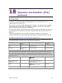
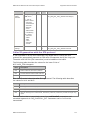
Revision History
Revision Release date
Notes
1.0
September, 1999 CYF/MVH, Natural Access Beta
1.1
December, 1999 EPS, Natural Access 3.0
1.2
July, 2000
1.3
September, 2000 NBS, Natural Access 3.0 and 4.0
NBS, Platform Support for Fusion 4.0
1.4
March, 2001
NBS, Natural Access 2000-2
1.5
April, 2001
MCM, Natural Access 2001-1 Beta
1.6
August, 2001
MCM, Natural Access 2001-1
1.7
November, 2001 SJC, NACD 2002-1 Beta
1.8
May, 2002
MVH, NACD 2002-1
1.9
April, 2003
LBG, Natural Access 2003-1
2.0
December, 2003 LBG, Natural Access 2004-1 Beta
2.1
April, 2004
2.2
November, 2004 LBG, Natural Access 2005-1 Beta
SRR, Natural Access 2004-1
2.3
March, 2005
LBG, Natural Access 2005-1
2.4
October, 2005
LBG, Natural Access 2005-1, SP 1
2.5
January, 2009
DEH, Natural Access R8.1
Last modified: January 23, 2009
Refer to the NMS Communications web site (www.nmscommunications.com) for
product updates and for information about support policies, warranty information,
and service offerings.
2
NMS Communications
Table Of Contents
Chapter 1: Introduction .................................................................................7
Chapter 2: Overview of NMS CAS ...................................................................9
PSTN trunk interfaces .................................................................................. 9
Trunk interface boards and the CT bus ........................................................ 9
NMS CAS protocols .....................................................................................10
NMS CAS software......................................................................................12
Trunk control programs (TCPs) ..................................................................12
Country and network variations .................................................................13
Protocol software package contents............................................................13
Available SLAC Files .................................................................................14
Chapter 3: Setting up NMS CAS....................................................................15
NMS CAS setup tasks..................................................................................15
Configuring NMS boards ..............................................................................15
AG 2000 board: Loop start protocol............................................................16
AG 4000 T1 board: WNK protocol ..............................................................18
AG 4000 E1 board: MFC-R2 protocol ..........................................................20
CG 6000C board: MFC-R2 protocol .............................................................21
Configuring TCPs........................................................................................23
Verifying TCP file locations ........................................................................23
Adding protocols for a particular country.....................................................24
Changing default parameters ....................................................................24
Changing a specified country.....................................................................26
Adding and changing parameter files automatically ......................................26
Starting CAS protocols ................................................................................27
Using nccStartProtocol .............................................................................27
Using CAS protocols.................................................................................28
Chapter 4: Using NCC service call control ....................................................29
NCC functions and solicited events................................................................29
NCC unsolicited events................................................................................37
Retrieving call information ...........................................................................40
NCC functions for retrieving call information ................................................40
NCC_CALL_STATUS structure ....................................................................40
NCC_CAS_EXT_CALL_STATUS structure......................................................42
nccPlaceCall and specifying extended information ...........................................43
nccDisconnectCall and specifying extended information....................................44
nccRejectCall and specifying extended information ..........................................44
Determining the capabilities of a protocol ......................................................45
Receiving billing pulses ...............................................................................45
NMS CAS TCP call control capabilities ............................................................45
AP2, EAM, EL7, EUC, EUC/SWE, FGD, GDS, and LPS .....................................45
MELCAS, NEC, MFC, MFS, OPS, R15, SS5, STA, and WNK..............................46
Chapter 5: NCC parameters..........................................................................47
NCC call control parameters.........................................................................47
NCC.X.ADI_START......................................................................................48
NCC.X.ADI_START.cleardown.......................................................................49
NCC.X.ADI_START.dial................................................................................50
NMS Communications
3
Table of Contents
NMS CAS for Natural Call Control Developer's Manual
NCC.X.ADI_START.dtmfdet ..........................................................................52
NCC.X.ADI_START.echocancel......................................................................53
NCC.X.ADI_PLACECALL ...............................................................................54
NCC.X.ADI_PLACECALL.callprog ...................................................................56
Chapter 6: Gateway application call control.................................................59
Call control and gateway applications ............................................................59
Accepting calls through gateway applications .................................................60
Rejecting calls through gateway applications ..................................................61
Chapter 7: Analog loop start (LPS) protocols ...............................................63
LPS signaling .............................................................................................63
Switch presenting calls to terminal equipment .............................................63
Terminal equipment placing calls ...............................................................64
LPS editable parameters..............................................................................64
LPS non-editable parameters .......................................................................66
LPS and NCC service call control...................................................................68
Using release guard .................................................................................68
Transferring calls on loop start lines ...........................................................68
Using loop current reversal parameters.......................................................68
Using caller ID ........................................................................................69
Chapter 8: Australian P2 (AP2) protocol ......................................................71
AP2 signaling.............................................................................................71
AP2 parameters .........................................................................................73
AP2 and NCC service call control...................................................................75
Chapter 9: EL7 protocol ...............................................................................77
EL7 signaling .............................................................................................77
EL7 parameters .........................................................................................80
Chapter 10: European digital CAS (EUC) protocol .......................................81
EUC country-specific signaling......................................................................81
EUC signaling for Italy (Norma CEI 103-1\7) ..................................................81
EUC signaling for Sweden (P7/P8) ................................................................83
Placing calls with P7.................................................................................84
Receiving calls with P7 .............................................................................85
Receiving calls with P8 .............................................................................86
EUC signaling for the Netherlands (ALS70D) ..................................................87
Signaling carried out by the outbound TCP ..................................................88
Signaling carried out by the inbound TCP ....................................................89
EUC register signaling .................................................................................90
EUC editable parameters .............................................................................91
EUC non-editable parameters.......................................................................92
EUC and NCC service call control ..................................................................94
Chapter 11: Feature group D (FGD) protocol ..............................................95
FGD signaling ............................................................................................95
FGD editable parameters .............................................................................97
FGD non-editable parameters ......................................................................97
FGD and NCC service call control ..................................................................99
4
NMS Communications
NMS CAS for Natural Call Control Developer's Manual
Table of Contents
Chapter 12: Ground start (GDS) protocol .................................................101
GDS signaling .......................................................................................... 101
Switch presenting calls to terminal equipment ........................................... 102
Terminal equipment placing calls ............................................................. 103
GDS editable parameters........................................................................... 104
GDS non-editable parameters .................................................................... 105
Chapter 13: Mercury exchange line (MELCAS) protocol ............................107
MELCAS signaling ..................................................................................... 107
MELCAS parameters ................................................................................. 109
Chapter 14: MF Socotel (MFS) protocol ....................................................111
MFS signaling .......................................................................................... 111
MFS editable parameters ........................................................................... 114
MFS non-editable parameters..................................................................... 115
MFS and NCC service call control ................................................................ 117
Receiving digits all at once...................................................................... 117
Receiving digits one at a time.................................................................. 117
Chapter 15: Multi-frequency R2 (MFC-R2) protocol ..................................119
MFC-R2 signaling ..................................................................................... 119
Signaling states..................................................................................... 120
Register signaling .................................................................................. 121
MFC-R2 editable parameters ...................................................................... 122
MFC-R2 non-editable parameters................................................................ 123
MFC-R2 and NCC service call control ........................................................... 128
Receiving digits all at once...................................................................... 128
Receiving digits one at a time.................................................................. 129
Chapter 16: NEC PBX protocol ..................................................................131
NEC PBX signaling .................................................................................... 131
NEC PBX parameters ................................................................................ 133
Chapter 17: Off-premises station (OPS) protocol .....................................135
OPS signaling .......................................................................................... 135
OPS editable parameters ........................................................................... 138
OPS non-editable parameters..................................................................... 139
Chapter 18: Operator workstation (STA) protocol ....................................141
STA signaling........................................................................................... 141
AG 2000 presents the call to the terminal equipment .................................. 141
Terminal equipment places a call to the AG 2000 ....................................... 142
Loop start protocol on digital CAS trunks................................................... 142
STA parameters ....................................................................................... 143
Chapter 19: Pulsed E and M (EAM) protocol .............................................145
EAM signaling .......................................................................................... 145
Signaling states..................................................................................... 145
Register signaling .................................................................................. 146
EAM editable parameters........................................................................... 147
EAM non-editable parameters .................................................................... 148
EAM and NCC service call control ................................................................ 152
Receiving digits all at once...................................................................... 152
NMS Communications
5
Table of Contents
NMS CAS for Natural Call Control Developer's Manual
Receiving digits one at a time.................................................................. 154
Chapter 20: Signaling system 5 (SS5) protocol ........................................155
SS5 signaling........................................................................................... 155
Signaling states..................................................................................... 156
Signal exchange .................................................................................... 157
SS5 editable parameters ........................................................................... 157
SS5 non-editable parameters ..................................................................... 158
SS5 and NCC service call control ................................................................ 159
Chapter 21: System R1.5 (R15) protocol ..................................................161
R15 signaling........................................................................................... 161
R15 editable parameters ........................................................................... 162
R15 non-editable parameters ..................................................................... 163
R15 and NCC service call control ................................................................ 165
Receiving digits all at once...................................................................... 165
Receiving digits one at a time.................................................................. 166
Chapter 22: Wink start protocols (digital and analog)..............................167
WNK signaling ......................................................................................... 167
WNK parameters ...................................................................................... 169
WNK and NCC service call control ............................................................... 172
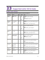
Chapter 23: Supported caller ID formats ..................................................173
BellCore caller ID data .............................................................................. 173
ETSI (France) caller ID data....................................................................... 174
NTT (Japan) caller ID data ......................................................................... 176
Caller ID generation with the STA protocol ................................................... 177
6
NMS Communications
1
Introduction
The NMS CAS for Natural Call Control Developer's Manual describes how to install
and run NMS channel associated signaling (CAS) protocol software with the Natural
Call Control (NCC) service. This manual is for developers of telephony and voice
applications who are using Natural Access. This document defines telephony terms
where applicable, but assumes that you are familiar with telephony concepts and
switching, and the C programming language.
NMS Communications
7
2
Overview of NMS CAS
PSTN trunk interfaces
Analog trunks with loop start signaling are the most common type of telephone
trunks found in residential installations. The network uses the presence or absence of
current flow in the telephone circuit as signaling information when establishing and
processing connections.
Digital trunks multiplex the signal of many different channels into one interface.
Digital trunks follow two basic standards around the world:
•
T1 trunk lines have a capacity of 1.544 Mbps, and typically handle 24
simultaneous telephone channels. T1 trunks are used in the United States,
Canada, Hong Kong, and Japan.
•
E1 trunk lines have a capacity of 2.048 Mbps and typically handle 30
simultaneous telephone channels. E1 trunks are used mainly in Europe, Asia,
and South America.
Digital trunks use signaling bits associated with voice channels to carry signaling
information. For a detailed description of T1 and E1 communications, see the
appropriate board installation and developer's manual.
Trunk interface boards and the CT bus
NMS trunk interface boards can connect to other boards in the same chassis over the
CT bus. The CT bus is a high-speed, time-division multiplexed digital telephony bus
between telephone line interface boards (such as AG 2000 boards), that allows
boards to share data, signaling, and switching information. You can add additional
DSP resources, analog line interfaces, or loop start line interfaces, by using other AG
2000 boards or board sets.
You can also use MVIP-compatible products from other manufacturers with NMS
boards.
For detailed information about a particular NMS board, refer to the appropriate board
installation manual.
Warning:
NMS obtains board-level approval certificates for supported countries. Some countries
require you to obtain system-level approvals before connecting a system to the public
telephone network. To learn what approvals you require, contact the appropriate regulatory
authority in the target country.
NMS Communications
9
Overview of NMS CAS
NMS CAS for Natural Call Control Developer's Manual
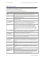
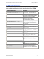
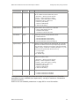
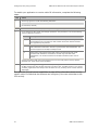
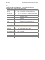
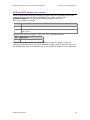
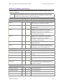
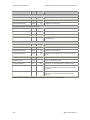
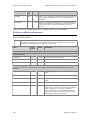
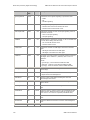
NMS CAS protocols
To communicate across a trunk line, parties must signal one another. The scheme
used to signal across a telephone line is called a protocol. Many different protocol
standards are in use throughout the world.
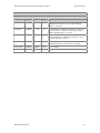
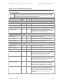
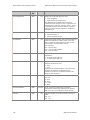
The following table describes the NMS CAS protocols:
Protocol
Description
Analog loop start
(LPS)
Includes protocols that use loop start signaling, where the presence or absence
of current flow is interpreted by a switch as protocol signaling events.
Australian P2 (AP2)
Used in Australia for connections between the PBX and some PSTN carriers. It
uses two-bit line signaling (derived from CCITT recommendation Q.421), and
in-band DTMF register signaling.
EL7
Implements the application computer variant of the EL7 protocol found on an
Ericsson MD110 PBX.
European digital
channel associated
signaling (EUC)
Includes channel associated signaling protocols used in certain European
countries. The protocols use two-bit line signaling specified by national
standards for use over E1 trunks. The register signaling is either carried by inband DTMF tones (not compelled) or by out-of-band decadic pulses.
Feature group D
(FGD)
Implements the specifications of the feature group D (FGD) switched access
service. This service provides interconnection to the BOC (Bell Operating
Companies) network for the provision of message telecommunications
service/wide area telecommunications service (MTS/WATS) and MTS/WATStype services. FGD service, which provides access to the trunk side of suitably
equipped BOC switching systems, is available for termination and originating
access.
Ground start (GDS)
NMS ground start protocols cover digital interfaces (T1 trunks) connected to a
private branch exchange (PBX) or PSTN switches. The protocol can handle two
signaling variations: FX (foreign exchange) and SA (special access).
Mercury exchange
line (MELCAS)
Implements the Mercury exchange line CAS protocol.
MF-Socotel (MFS)
Conforms to the Spanish National Specifications for channel associated
signaling over E1 trunks. It uses single bit steady-state line signaling and MFSocotel MF compelled in-band register signaling.
Multi-frequency
compelled protocols
based on the R2
standard (MFC)
Includes the CCITT Signaling System R2 (Recommendations Q.421 to Q.442,
CCITT Blue Book, 1988) implementation and numerous national variations.
These protocols run on E1 trunks and use two-bit line signaling on the signaling
channel associated with each voice channel and in-band MF compelled register
signaling.
NEC PBX (NEC)
A digital line interface protocol that implements the specifications of the 30 DLI
using the PA-30 DTS package (Annex 303-15-B 2/2 from NEC, NEC Australia
PTY, LTD).
Off-premises station
(OPS)
The NMS OPS protocol covers only digital interfaces. The protocol can handle
T1 or E1 digital trunks, of signaling types FX (foreign exchange) or SA (special
access).
Operator
workstation (STA)
Other side of the analog loop start protocol used to implement stations that
connect to analog phones.
Pulsed E and M
(EAM)
Includes country-specific protocols that use one-bit line signaling in a pulsed
form, and variations on the compelled in-band MF register signaling specified
by the CCITT in the 1988 Blue Book. These protocols run on E1 trunks and are
specified in different countries by national regulatory agencies.
10
NMS Communications
NMS CAS for Natural Call Control Developer's Manual
Overview of NMS CAS
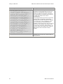
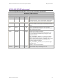
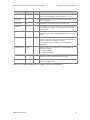
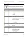
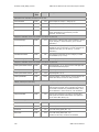
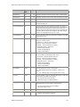
Protocol
Description
Signaling system 5
(SS5)
Specified by the CCITT Recommendations Q.140 to Q.154 (CCITT Red Book,
Volume VI Fascicle VI.2, Geneva 1985). The protocol uses in-band compelled
signal frequency tones to perform line signaling and in-band MF tones for
register signaling. Since no signaling bits are used, this protocol works the
same way on T1 and E1 trunks.
System R1.5 (R15)
Includes channel associated signaling protocols used for E1 lines in Russia
(based on CCITT recommendations Q.511 and Q.544). The protocols use twobit steady-state line signaling. Register signaling is either carried by in-band MF
tones (MF acknowledged pulses) or by out-of-band decadic pulses. Two R15
protocol software modules are included with NMS CAS. One is used (r150) for
controlling inbound calls and the other (r151) is used for controlling outbound
calls.
Digital and analog
wink start (WNK)
Includes protocols used on T1 in the USA, Hong Kong, and Taiwan. The
protocol uses one-bit signaling, two-bit signaling, or presence or absence of
current, and owes its name to the wink (brief presence of current or variation
of the signaling bit) that the inbound side uses to acknowledge line seizure.
Register signaling is performed by in-band DTMF or MF tones, or by out-ofband decadic pulses.
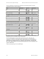
Most of the protocols in these families have country-specific variations. NMS provides
parameter files that determine how protocols interact with telephone networks in
different countries. The package for each country contains software modules you
need to download to enable telephony boards to communicate with telephone
networks in that country.
NMS Communications
11
Overview of NMS CAS
NMS CAS for Natural Call Control Developer's Manual
NMS CAS software
This topic describes:
•
Trunk control programs (TCPs)
•
Country and network variations
•
Protocol software package contents
•
Available SLAC files
Trunk control programs (TCPs)
The Natural Call Control (NCC) service provides a call control API that enables an
application to establish inbound or outbound calls and to perform call transfer,
blocking, and other operations. To keep this API relatively simple and protocolindependent, the communication with the trunk is performed by another software
entity called a trunk control program (TCP). The TCP translates commands from the
NCC service into channel associated signaling (CAS) appropriate for the particular
protocol running on the trunk, and translates protocol-specific trunk events into NCC
service events.
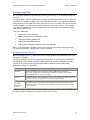
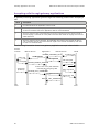
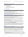
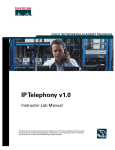
The following illustration shows the TCP's role in an application:
Application
commands
events
Natural Access
context
(Other services)
Other
commands
Other
events
NMS
board
NCC service (call control)
TCP
(call control)
commands
TCP
(call control)
events
TCP
Trunk signaling
Trunk
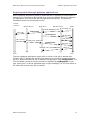
NMS CAS software provides a series TCPs for a variety of protocols. The TCP is
loaded into the on-board memory of a line interface board when you configure the
board. For applications that must support multiple protocols and/or protocol
variations simultaneously, more than one TCP can be loaded to the telephony board
at the same time. Each line supports one TCP at a time.
For more information, refer to Configuring NMS boards on page 15.
12
NMS Communications
NMS CAS for Natural Call Control Developer's Manual
Overview of NMS CAS
Country and network variations
Each country uses its own variation of a protocol. In addition to the basic TCP
software, each protocol software package contains several binary parameter files (.pf
files) that program the protocol for a particular country or network variation. Natural
Access applications automatically load these parameters at initialization time.
For more information about loading parameters, refer to NMS CAS setup tasks on
page 15.
Warning:
You can change only a subset of parameters for each CAS protocol without affecting
regulatory approvals. Editing other parameters may result in violations of country-specific
regulations. For information about what parameters you can and cannot edit for a specific
protocol, refer to the protocol topics in this document.
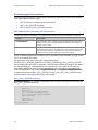
Protocol software package contents
The software package for a given country-specific protocol includes:
•
readme file (common for all protocols and countries)
•
One or more trunk control programs (TCPs)
•
Sample country-specific configuration files
•
Four country-specific binary parameter files
•
Four editable (ASCII) country-specific parameter files
•
One or more SLAC files (for AG 2000 boards)
When you install multiple protocols or install protocols for multiple countries, several
versions of each component are created. For more information on the installed
components for a protocol, refer to NMS CAS setup tasks on page 15.
Natural Access includes several call control demonstration programs that can use any
of the NMS CAS protocols to place or receive calls. Refer to the Natural Call Control
Service Developer's Reference Manual for information about running these programs.
NMS Communications
13
Overview of NMS CAS
NMS CAS for Natural Call Control Developer's Manual
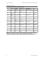
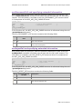
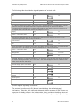
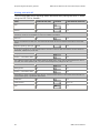
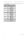
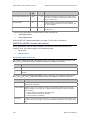
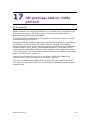
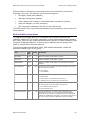
Available SLAC Files
The following SLAC files are available under NCC:
File
Country
Signaling
module
Line impedance,
ohm
Termination
impedance, ohm
Use
a2eurlsc.slc
Australia
Loop start/
CTR21
270 + (750 ||
150nF)
270 + (750 || 150nF)
Default
a2usals6.slc
North
America
Loop start/US
600+ 2.16uF
600+ 2.16uF
Tests, PBX,
default
a2usals9.slc
North
America
Loop start/US
900
600+ 2.16uF
PBX
a2usalsn.slc
North
America
Loop start/US
(800//0.005uF) +
100
600+ 2.16uF
Unloaded
loops
a2eurlsc.slc
Europe
Loop start/
CTR21
270 + (750 ||
150nF)
270 + (750 || 150nF)
Default
a2jpnls6.slc
Japan
Loop start/US
600+ 2.16uF
600+ 2.16uF
Tests, PBX,
default
a2jpnls9.slc
Japan
Loop start/US
900
600+ 2.16uF
PBX
a2jpnlsn.slc
Japan
Loop start/US
(800//0.005uF) +
100
600+ 2.16uF
Unloaded
loops
a2canls6.slc
Canada
Loop start/US
600+ 2.16uF
600+ 2.16uF
Tests, PBX,
default
a2canls9.slc
Canada
Loop start/US
900
600+ 2.16uF
PBX
a2canlsn.slc
Canada
Loop start/US
(800//0.005uF) +
100
600+ 2.16uF
Unloaded
loops
Note: For the purposes of this table, Europe includes Austria, Belgium, Denmark,
Finland, France, Germany, Greece, Iceland, Ireland, Italy, Liechtenstein,
Luxembourg, Netherlands, Norway, Portugal, Spain, Sweden, and Switzerland.
14
NMS Communications
3
Setting up NMS CAS
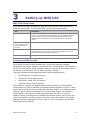
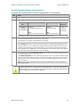
NMS CAS setup tasks
You must set up NMS CAS before an application can use call control functions to
place and answer calls. To set up NMS CAS, perform the following tasks:
Task
Description
Configure the boards
Specify the TCPs to be loaded for an application. One or more sample
country- and protocol-specific configuration files are installed with each
protocol software package. These sample configuration files include
statements that make the protocol run appropriately for a particular
country.
Configure the trunk
control programs (TCPs)
for country-specific
variations
Add protocols for a particular country, and change default parameters.
Initialize Natural Access
Initialize Natural Access and services (including the NCC service, create
contexts and queues, and open services). For information, refer to the
Natural Access Developer's Reference Manual.
Start the CAS protocols
Use the NCC service to start a TCP.
Configuring NMS boards
Specify configuration information for all boards in the system in an NMS OAM system
configuration file and in board keyword files. These files reference managed
components that specify whether a board performs CT bus switching, which board is
the CT bus clock master, which software modules to transfer to the board's memory
on startup (including which TCPs to load), and other settings.
This topic provides the following sample NMS OAM configuration files:
•
AG 2000 board: Loop start protocol
•
AG 4000 T1 board: WNK protocol
•
AG 4000 E1 board: MFC-R2 protocol
•
CG 6000C board: MFC-R2 protocol
Run oamsys to configure the boards based on the information in the NMS OAM
configuration file. oamsys transfers all software modules specified in the file to each
board, and performs any other configuration activities needed. You should also start
oammon, which monitors the boards for errors and other events. Use oamcfg to
change system information or board parameters after the system is running.
oamsys, oamcfg, and oammon are installed with Natural Access. oamsys.cfg is the
system configuration file that contains information about the boards in the system
and specifies which configuration files to load. For more information, see the NMS
OAM System User's Manual.
NMS Communications
15
Setting up NMS CAS
NMS CAS for Natural Call Control Developer's Manual
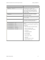
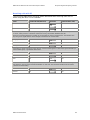
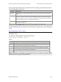
The following table lists the sample NMS OAM board keyword files installed with NMS
CAS (where prt indicates the protocol and cty indicates the country where used):
File
a4piprt.cfg
a4piprtcty.cfg
a2piprt.cfg
a2piprtcty.cfg
Location
Windows: \nms\ag\cfg
For AG 4000/C and AG 4040/C boards.
UNIX:/opt/nms/ag/cfg
Default example board keyword file to configure one board
with all the modules and settings to run protocol prt. It
reflects the last country installed in the system for the
protocol prt.
Windows:
\nms\ag\cfg\country
For AG 4000/C and AG 4040/C boards.
UNIX:
/opt/nms/ag/cfg/country
Example board keyword file to configure one board with all
the modules and settings to run the protocol prt in the
country cty. A different file is installed for each country.
Windows: \nms\ag\cfg
For AG 2000/C boards.
UNIX: /opt/nms/ag/cfg
Default example board keyword file to configure one board
with all the modules and settings to run protocol prt. It
reflects the last country installed in the system for the
protocol prt.
Windows:
\nms\ag\cfg\country
For AG 2000/C boards.
UNIX:
/opt/nms/ag/cfg/country
c6prtcty.cfg
Description
Windows:
\nms\cg\cfg\country
UNIX:
/opt/nms/cg/cfg/country
Example board keyword file to configure one board with all
the modules and settings to run the protocol prt in the
country cty. A different file is installed for each country.
For CG boards.
Example CG board keyword file to configure one board
with all the modules and settings to run the protocol prt in
the country cty. A different file is installed for each
country.
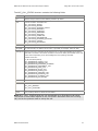
AG 2000 board: Loop start protocol
The following sample NMS OAM board keyword file describes an AG 2000 board using
a loop start protocol (LPS) in the USA with 8 ports with 600 ohm network line
impedance. The board is configured to run as a stand alone unit. CAS protocolspecific items are bold.
Board keyword file sample
Description
TCPFiles[0] = nocc.tcp
TCPFiles[1] = lps0.tcp
Indicates which TCP to load to the board. This
setting is protocol-specific.
The first statement loads the no call control
protocol. The second statement loads the loop
start protocol.
XLaw = mu-LAW
Defines voice signaling bit patterns sent to the
network when the TCP is not active. This is
country-specific.
mu-law is a companding algorithm used for
digital trunks. AG 2000 boards need to know the
originating companding law to generate an
analog voice signal.
16
NMS Communications
NMS CAS for Natural Call Control Developer's Manual
Setting up NMS CAS
Board keyword file sample
Description
DLMFiles[0] = gtp.leo
DLMFiles[1] = voice.leo
DLMFiles[2] = svc.leo
Specifies optional runtime components to be
transferred to the coprocessor on the board (leo
files are loadable executable objects).
The first statement loads the trunk protocol
engine. The second one loads the play and
record manager. The third one loads the DSP
function manager.
NetworkInterface.Analog[0..7].ConfigFile =
a2usals6.slc
Specifies the AG 2000 board with loop start
signaling type and 600 ohm line impedance.
Country-specific settings.
Clocking.HBus.ClockSource = OSC
Specifies the source from which this board
derives its timing. Setting OSC defines the board
as a clock master.
Clocking.HBus.ClockMode = STANDALONE
Specifies the CT bus clock that the board drives.
Set a board in standalone mode so the board
references its own clocking information.
DSP.C5x.DSPFiles[0] = signal
DSP.C5x.DSPFiles[1] = tone
DSP.C5x.DSPFiles[2] = dtmf
DSP.C5x.DSPFiles[3] = mf
DSP.C5x.DSPFiles[4] = callp
DSP.C5x.DSPFiles[5] = ptf
DSP.C5x.DSPFiles[6] = echo.m54
DSP.C5x.DSPFiles[7] = oki.m54
DSP.C5x.DSPFiles[8] = rvoice.m54
DSP.C5x.DSPFiles[9] = voice.m54
DSP.C5x.DSPFiles[10] = wave.m54
Installs DSP program files. For this
configuration, you need at least the statements
shown.
NMS Communications
The following DSP functionality is defined by this
configuration:
•
Out-of-band channel associated signaling
•
Beep, tone generation, dial
•
DTMF and silence/energy detectors
•
MF detection
•
Call progress detection
•
Pure tone filters
•
Echo cancellation
•
OKI-style play, record
•
RAW voice
•
NMS ADPCM play and record
•
WAVE-style play, record
17
Setting up NMS CAS
NMS CAS for Natural Call Control Developer's Manual
AG 4000 T1 board: WNK protocol
The following sample NMS OAM board keyword file describes one AG 4000 T1 board
set up using a wink start protocol (WNK) for the USA. CAS protocol-specific items are
bold.
Note: Refer to the AG 4040 Installation and Developer's Manual and the AG 4040C
Installation and Developer's Manual for information about configuring the AG 4040
and AG 4040C boards.
Board keyword file sample
Description
TCPFiles[0] = wnk0.tcp
Indicates the TCP to load to the board. The setting
here is protocol-specific.
The statement loads the wink start protocol.
Xlaw = MU-LAW
Defines the switch idle codes.
DLMFiles[0] = gtp.leo
DLMFiles[1] = voice.leo
DLMFiles[2] = svc.leo
Specifies optional runtime components to be
transferred to the coprocessor on the board (leo files
are loadable executable objects).
The first statement loads the trunk protocol engine.
The second one loads the voice manager. The third
one loads the DSP function manager.
Clocking.HBus.ClockSource = NETWORK
Specifies the source from which this board derives its
timing.
Specifies a digital trunk as the board's clock source.
Note: If you select NETWORK, you must complete
Clocking.HBus.ClockSourceNetwork.
Clocking.HBus.ClockSourceNetwork = 1
Specifies the number of a trunk that the board uses as
an external network clocking source for its internal
clock.
Clocking.HBus.ClockMode = STANDALONE
Specifies the CT bus clock that the board drives.
Sets a board in standalone mode so the board
references its own clocking information.
NetworkInterface.T1E1[0..3].FrameType
= D4
NetworkInterface.T1E1[0..3].LineCode =
AMI_ZCS
18
Sets up trunk information for the board to match the
connected equipment.
NMS Communications
NMS CAS for Natural Call Control Developer's Manual
Setting up NMS CAS
Board keyword file sample
Description
DSP.C5x.DSPFiles[0] = tone
DSP.C5x.DSPFiles[1] = callp
DSP.C5x.DSPFiles[2] = dtmf
DSP.C5x.DSPFiles[3] = voice
DSP.C5x.DSPFiles[4] = mf
DSP.C5x.DSPFiles[5] = ptf
# Uncomment and put in the correct
counter:
# DSP.C5x.DSPFiles[X] = rvoice
# DSP.C5x.DSPFiles[X] = okiply
# DSP.C5x.DSPFiles[X] = okirec
# DSP.C5x.DSPFiles[X] = wavply
# DSP.C5x.DSPFiles[X] = wavrec
Installs DSP program files. For this configuration, you
need at least the statements shown. The following DSP
functionality is defined by this configuration:
NMS Communications
•
Beep, tone generation, dial
•
Call progress detection
•
DTMF and silence/energy detectors
•
NMS ADPCM play and record
•
MF detection, compelled sequences
•
RAW voice
•
OKI-style play
•
OKI-style record
•
WAVE-style play
•
WAVE-style record
19
Setting up NMS CAS
NMS CAS for Natural Call Control Developer's Manual
AG 4000 E1 board: MFC-R2 protocol
The following sample NMS OAM board keyword file describes one AG 4000 E1 board
set up using a MFC-R2 protocol. CAS protocol-specific items are bold.
Note: Refer to the AG 4040 Installation and Developer's Manual and the AG 4040C
Installation and Developer's Manual for information about configuring the AG 4040
and AG 4040C boards.
Board keyword file sample
Description
TCPFiles[0] = mfc0.tcp
Indicates the TCP to load to the board. The setting
here is protocol-specific.
The statement loads the MFC-R2 TCP.
VoiceIdleCode = 0xd5
SignalIdleCode = 0x9
Defines voice signaling bit pattern sent to the network
when the TCP is not active. This is country-specific.
Specifies the A-Law silence, idle bit pattern.
LoadFile = ag4000.lod
RunFile = ag4000.cor
Specifies runtime components to be loaded to the
board. This is board and protocol specific.
Note: If you are using an AG 4040/C board, specify
ag4040.lod and ag4040.cor for these files.
DLMFiles[0] = gtp.leo
DLMFiles[1] = voice.leo
DLMFiles[2] = svc.leo
Specifies optional runtime components to be
transferred to the coprocessor on the board (leo files
are loadable executable objects).
The first statement loads the trunk protocol engine.
The second one loads the voice manager. The third one
loads the DSP function manager.
Clocking.HBus.ClockSource = NETWORK
Specifies the source from which this board derives its
timing.
Specifies a digital trunk as the board's clock source.
Note: If you select NETWORK, you must complete
Clocking.HBus.ClockSourceNetwork.
Clocking.HBus.ClockSourceNetwork = 1
Specifies the number of a trunk that the board uses as
an external network clocking source for its internal
clock.
Clocking.HBus.ClockMode = STANDALONE
Specifies the CT bus clock that the board drives.
Sets a board in standalone mode so the board
references its own clocking information or a digital
network source.
NetworkInterface.T1E1[0..3].FrameType
= CEPT
NetworkInterface.T1E1[0..3].LineCode =
HDB3
20
Sets up trunk information for the board to match the
connected equipment.
NMS Communications
NMS CAS for Natural Call Control Developer's Manual
Setting up NMS CAS
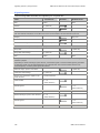
CG 6000C board: MFC-R2 protocol
The following sample board keyword file describes a CG 6000C board using an MFCR2 protocol. For more information about board-specific entries, refer to the CG
6000C Installation and Developer's Manual. CAS protocol-specific items are bold.
Board keyword file sample
Description
Clocking.HBus.ClockSource = OSC
Clocking.HBus.ClockSourceNetwork = 1
Specifies the source from which this board
derives its timing. Settings OSC define the
board as a clock master.
Clocking.HBus.ClockMode = STANDALONE
Specifies the CT bus clock that the board drives.
Sets a board in standalone mode so the board
references its own clocking information.
TCPFiles = mfc0.tcp
Indicates the TCP to load to the board. The
setting here is protocol-specific.
The statement loads the MFC-R2 TCP.
DSPStream.VoiceIdleCode[0..3] = 0xd5
DSPStream.SignalIdleCode[0..3] = 0x9
Defines the voice signaling bit pattern sent to
the network when the TCP is not active. This is
country-specific. Specifies the A-Law silence,
idle code pattern.
NetworkInterface.T1E1[0..3].Type = E1
Specifies the trunk type for each trunk on the
board.
NetworkInterface.T1E1[0..3].Impedance =
G703_120_OHM
Specifies the type of cable connecting to the
telephone network.
NetworkInterface.T1E1[0..3].SignalingType =
CAS
Determines how voice and signaling information
is routed to and from the E1 or T1 trunk and
DSP resources.
NetworkInterface.T1E1[0..3].FrameType = CEPT
Defines the framing format for the current
board or trunk.
NetworkInterface.T1E1[0..3].LineCode = HDB3
Specifies the ones density maintenance method
used on the trunk line to maintain a clear
channel transmission.
DLMFiles[0] = cg6krun
Specifies an optional runtime component
(modular extension to the core file) to be
transferred to the board by the configuration
file.
DSP.C5x[0..31].Libs[0] = cg6kliba
Specifies the DSP library file name.
DSP.C5x[0..31].XLaw = A_LAW
Determines the DSP hardware companding
mode.
Note: All DSPs must have the same value.
DSP.C5x[0].Files = qtsignal callp tone \
dtmf ptf mf echo
DSP.C5x[1..31].Files = voice tone dtmf \
echo rvoice callp ptf wave oki ima gsm_ms
g726 mf
NMS Communications
Specifies digital signal processor function
modules (DPFs) loaded to board DSPs for
applications to use on a per-call/channel basis.
21
Setting up NMS CAS
NMS CAS for Natural Call Control Developer's Manual
Board keyword file sample
Description
Resource[0].Definitions = ( dtmf.det_all & \
echo.ln20_apt25 & ptf.det_2f & \
tone.gen & \callp.gnc & ptf.det_4f & \
( (rvoice.rec_mulaw & rvoice.play_mulaw) | \
(rvoice.rec_alaw & rvoice.play_alaw) | \
(rvoice.rec_lin & rvoice.play_lin) | \
(voice.rec_16 & (voice.play_16_100 | \
voice.play_16_150 | voice.play_16_200)) | \
(voice.rec_24 & (voice.play_24_100 | \
voice.play_24_150 | voice.play_24_200)) | \
(voice.rec_32 & (voice.play_32_100 | \
voice.play_32_150 | voice.play_32_200)) | \
(voice.rec_64 & (voice.play_64_100 | \
voice.play_64_150 | voice.play_64_200)) | \
(wave.rec_11_16b & wave.play_11_16b) | \
(wave.rec_11_8b & wave.play_11_8b) | \
(oki.rec_24 & (oki.play_24_100 | \
oki.play_24_150 | oki.play_24_200)) | \
(oki.rec_32 & (oki.play_32_100 | \
oki.play_32_150 | oki.play_32_200)) | \
(ima.rec_24 & ima.play_24) | \
(ima.rec_32 & ima.play_32) | \
(gsm_ms.frgsm_rec & gsm_ms.frgsm_play) | \
g726.rec_32 | g726.play_32) )
Provides a relational string of DPFs that
describes the functionality that can occur on a
single port, and describes how the functions
execute in relation to each other. The DPFs in
this string specify the functions that execute on
the DSPs and whether they execute
simultaneously.
DebugMask = 0x0
Specifies the type and level of tracing that the
board performs.
22
Resource[x].Definitions specifies the processing
functions that are available to applications
during the life of a call or channel. For example,
if you expect to run echo cancellation at any
time on the board, an echo DPF must be
specified in this keyword. Since echo runs at the
same time as the decoder and encoder in the
universal ports full duplex implementation, the
Resource string must combine echo (using the
AND operator) with the decoder and the
encoder.
NMS Communications
NMS CAS for Natural Call Control Developer's Manual
Setting up NMS CAS
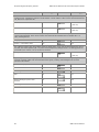
Configuring TCPs
Many protocol features can differ from country to country, or even within the same
country.
Configure NMS CAS TCP parameters to specify the appropriate behavior for different
countries and networks. When you install NMS CAS for NCC, you specify the country
and protocols to use. NMS CAS runs protocols for only one country at a time (the last
country loaded). You can load multiple protocols for a single country. You can also
override the defaults for particular parameters by editing the corresponding ASCII
.par file for that country.
This topic describes:
•
Verifying TCP file locations
•
Adding protocols for a particular country
•
Changing default parameters
•
Changing a specified country
•
Adding and changing parameter files automatically
Many of the protocols included in this manual can do more than is described here.
For more information, contact NMS Communications.
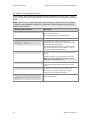
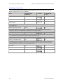
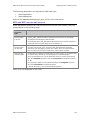
Verifying TCP file locations
Before configuring a TCP, make sure that the appropriate CAS parameter files are in
the proper locations.
A binary parameter file for the target country must be in the directory specified by
the AGLOAD environment variable. These binary files contain compiled-in default
values for all of the country-specific parameters. Natural Access loads these
parameters when it is initialized.
Parameter file
Description
nccxadi.pf
Defines the Natural Access parameter category NNC.X.ADI_START and
NCC.X.ADI_PLACECALL. These parameter categories include all of the countryspecific parameters for AG and CG boards.
nccstart.pf
Defines the Natural Access parameter category NCC.START. NCC.START parameters
include country-specific parameters for the last country installed.
nccxprt.pf
Defines the Natural Access parameter category NCC.X.ADI_prt. This category holds
all protocol-specific parameters for the specified protocol. The parameter default
values defined by this file apply to the TCP implementing the protocol for the last
country installed.
where prt
indicates the
protocol.
A single country-specific instance of the binary parameter file is in the AGLOAD path
for each protocol. Otherwise, the NCC service will not start.
NMS Communications
23
Setting up NMS CAS
NMS CAS for Natural Call Control Developer's Manual
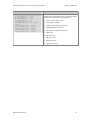
The Natural Access installation program installs backup copies of the binary
parameter files. The following table lists the names and locations of these backup
files. Where prt indicates the protocol and cty indicates the country where used:
Binary parameter
file
Backup file
Windows backup file
location
UNIX backup file
location
nccxprt.pf
nccxprtcty.pf
\nms\ag\cfg\country
/opt/nms/ag/cfg/country
nccxadi.pf
nccxadicty.pf
\nms\ag\cfg\country
/opt/nms/ag/cfg/country
nccstart.pf
nccstartcty.pf
\nms\ag\cfg\country
/opt/nms/ag/cfg/country
Adding protocols for a particular country
To manually add protocols for a particular country, copy the binary parameter files
for that country/protocol from the backup directory to the binary parameter file
directory:
Copy this file...
nccxprtcty.pf
From this directory...
To this directory...
Windows: \nms\ag\cfg\country
Windows: \nms\ag\cfg
or
or
UNIX: /opt/nms/ag/cfg/country
UNIX: /opt/nms/ag/cfg
And rename the file to...
nccxprt.pf
prt indicates the protocol and cty indicates the country where used.
Changing default parameters
To reset the values of the country-specific parameters, use the ASCII parameter
value definition files. These files can be used to set the parameter values systemwide, using ctdaemon, or the application can parse the values for dynamic parameter
management with Natural Access functions.
Parameters within the ASCI parameter files fall within the following classes:
•
Those that you can change to fit the application's needs
•
Those that should not be changed because they have regulatory relevance.
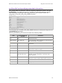
The following table lists the ASCII parameter value definition files:
File
nccxprt.par
Location
Windows:
\nms\ctaccess\cfg
UNIX:
/opt/nms/ctaccess/cfg
nccxadi.par
Windows:
\nms\ctaccess\cfg\
UNIX:
/opt/nms/ctaccess/cfg
nccstart.par
Windows:
\nms\ctaccess\cfg
UNIX:
/opt/nms/ctaccess/cfg
24
Description
Defines the Natural Access parameter category NCC.X.ADI_prt.
This category holds all protocol-specific parameters for the prt
protocol. The parameter default values defined by these files
apply to the TCP implementing the protocol prt for the last
country installed.
Defines the Natural Access parameter category
NNC.X.ADI_START and NCC.X.ADI_PLACECALL. These
parameter categories include all of the country-specific
parameters for AG and CG boards.
Defines the Natural Access parameter category NCC.START.
NCC.START parameters include all of the country-specific
parameters for the last country installed.
NMS Communications
NMS CAS for Natural Call Control Developer's Manual
Setting up NMS CAS
Manually changing default TCP parameters
Complete the following steps to manually change default TCP parameters:
Step
Action
1
Make changes to the values in ASCII parameter files (*.par file) and save the changes.
2
Copy ASCII parameter files to the appropriate directory and rename:
Copy this
file...
nccxprtcty.par
nccxadicty.par
nccstartcty.par
From this directory...
To this directory...
Windows:
\nms\ctaccess\cfg\country
Windows:
\nms\ctaccess\cfg
or
or
UNIX:
/opt/nms/ctaccess/cfg/country
UNIX:
/opt/nms/ctaccess/cfg
And rename
the file to...
nccxprt.par
nccxadi.par
nccstart.par
prt indicates the protocol and cty indicates the country where used.
3
Load the changed parameters in one of the following ways:
Use ctdaemon to set system-wide parameters by entering:
ctdaemon -f filename
where filename can be one of the previously listed files or an edited file containing all of the
changed parameters. You can add all the changed parameters to the ctapar section of cta.cfg.
Any Natural Access application started subsequently on the system will share the parameter
values contained in the *prt.par file, as long as ctdaemon is kept running. Refer to the Natural
Access Developer's Reference Manual for more information.
4
In your application, call ctaLoadParameterFile and provide the appropriate parameter file as
the function's argument.
Call ctaSetParmByName for each parameter specified in the file. This sets new default values.
Use this procedure for systems running in command line mode in Windows and other operating
systems. When running as a Windows service, copy the modified parameters to cta.cfg. Then
restart the service.
Note: You must modify parameters before starting the specified TCP for the new parameter
values to take effect.
Warning:
You can change only a subset of parameters for each CAS protocol without affecting
regulatory approvals. For information about what parameters you can and cannot edit for a
specific protocol, refer to the protocol topics in this document. Editing other parameters may
result in violations of country-specific regulations.
NMS Communications
25
Setting up NMS CAS
NMS CAS for Natural Call Control Developer's Manual
Changing a specified country
To change the specified country for NMS CAS protocols, copy the country specific
binary parameters files for that country and protocols from the backup directory to
the binary parameter file directory:
Copy this file...
From this directory...
To this directory...
And rename the file to...
nccxprtcty.pf
Windows: \nms\ag\cfg\country
Windows:\nms\ag\cfg
nccxprt.pf
nccxadicty.pf
or
or
nccxadi.pf
nccstartcty.pf
UNIX: /opt/nms/ag/cfg/country
UNIX: /opt/nms/ag/cfg
nccstart.pf
prt indicates the protocol and cty indicates the country where used.
Note: You can use NMS CAS protocols for only one country at a time. The country
used is the last country whose protocols were loaded.
Adding and changing parameter files automatically
NMS CAS for Natural Call Control software includes a switchpar utility for adding and
changing binary and ASCII parameter files for particular protocols. switchpar
automatically copies and renames the appropriate parameter files to the correct
directories and file names.
To use switchpar, run the following command from the command line:
Operating system
Command
Windows
switchpar cty prt nmsroot
UNIX
switchpar.sh cty prt
Where:
•
cty indicates the three letter country abbreviation
•
prt indicates the three letter protocol abbreviation
•
nmsroot indicates the root directory for NMS software on the system (the
default is \nms).
Note: Running switchpar for a protocol that has already been installed automatically
overwrites any changes you may have made to that protocol's editable parameters.
If ctdaemon is running when you change parameters, stop and restart the program
to initialize the parameters.
26
NMS Communications
NMS CAS for Natural Call Control Developer's Manual
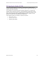
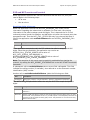
Setting up NMS CAS
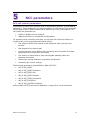
Starting CAS protocols
Before starting a CAS protocol, the application must initialize Natural Access and
obtain context handles. The TCP parameters are automatically loaded during
initialization. For information about initializing Natural Access and obtaining context
handles, refer to the Natural Access Developer's Reference Manual.
This topic provides the following information:
•
Using nccStartProtocol
•
Using CAS protocols
Using nccStartProtocol
When a context is open and the TCP parameters are loaded, the application can start
a protocol on that context according to the loaded parameters (see Configuring TCPs
on page 23). Invoke nccStartProtocol to start a TCP. After a TCP is started on a
context, the application can use call control functions to place and answer calls on
that context.
Note: To start a TCP from within an application, the TCP must have been
downloaded to the board during system initialization. The configuration utility
downloads all TCPs specified in the board keyword file. For more information about
the board keyword file, see Configuring NMS boards on page 15.
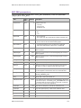
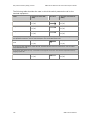
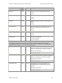
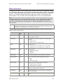
nccStartProtocol requires a TCP name as one of its arguments. CAS TCPs include
the following:
Protocol
TCP name
Analog loop start
lps0
Australian P2
ap20
EL7
el70
European digital CAS
euc0
Feature group D
fgd0
Digital ground start
gds0
MELCAS
mel0
MF-Socotel
mfs0
Multi-frequency compelled R2
mfc0
NEC PBX
nec0
Off-premises station
ops0
Operator workstation
sta0
Pulsed E and M
eam0
Signaling system 5
ss50
System R1.5 (inbound calls)
r150
System R1.5 (outbound calls)
r151
Wink start (digital and analog)
wnkx (x=0,1)
NMS Communications
27
Setting up NMS CAS
NMS CAS for Natural Call Control Developer's Manual
After the application calls nccStartProtocol, it receives
NCCEVN_STARTPROTOCOL_DONE. If the TCP is started successfully, the event value
field contains CTA_REASON_FINISHED. Otherwise, the value field contains a reason
code that describes the error that occurred.
If your application terminates, all channels associated with the application are
terminated, the TCP shuts down, and the bit pattern specified in the IdleCode
statement in the board keyword file is signaled on the line.
Using CAS protocols
On AG boards, DSP functions started by the TCP (for example, DTMF detection)
cannot be active while calls are in the connected state. For this reason, when calling
nccStartProtocol, the value of the NCC service parameter mediamask (in the
NCC.X.ADI_START_PARMS structure) must be set to 0.
If mediamask is not set to 0, the TCP does not start and the application receives the
NCCEVN_STARTPROTOCOL_DONE event with the reason
NCC_REASON_OUT_OF_RESOURCES. The application must then set mediamask to
zero before starting the protocol again.
For information about NCC.X.ADI_START parameters, refer to NCC call control
parameters on page 47.
For information about managing DSP resources on CG boards, refer to the
appropriate board installation manual.
28
NMS Communications
4
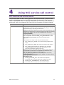
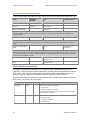
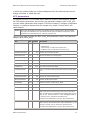
Using NCC service call control
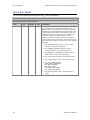
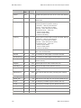
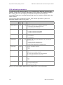
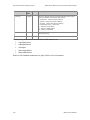
NCC functions and solicited events
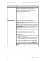
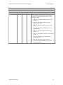
The following table lists NCC service functions and solicited events. Solicited events
signify acknowledgments from the TCP of particular function calls. Functions are
listed in alphabetical order. For detailed documentation of the functions, parameters,
and events, refer to the Natural Call Control Service Developer's Reference Manual.
Function
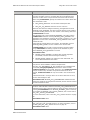
nccAcceptCall
Description and associated events
Accepts an incoming call without answering or rejecting it. This allows
the application to perform media functions (such as playing a voice file)
before connecting (or rejecting) an inbound call.
Note: Not all protocols support this function and the accepting state. The
application can determine if the protocol supports this state by examining
the NCC_CAP_ACCEPT_CALL bit in the capabilitymask returned by
nccQueryCapability.
If the remote party disconnects while the application accepts the call,
then the application receives NCCEVN_CALL_DISCONNECTED. In this
case, no NCCEVN_ACCEPTING_CALL event is delivered to the
application.
The application can accept a call using the following modes:
•
NCC_ACCEPT_PLAY_SILENT: Do not play anything (digital trunks
only).
•
NCC_ACCEPT_PLAY_RING: Play a ring tone (works on all trunks).
•
NCC_ACCEPT_USER_AUDIO: The application may generate a
recorded message. If the remote party disconnects, the TCP
interrupts the message (digital trunks only).
Note: NCC_ACCEPT_PLAY_RING and NCC_ACCEPT_USER_AUDIO are
not supported by all protocols. The application can determine if the
protocol supports this capability by examining the
NCC_CAP_MEDIA_IN_SETUP bit in the capabilitymask returned by
nccQueryCapability. NCC_ACCEPT_PLAY_SILENT is the default accept
mode supported by all protocols.
Associated events:
NMS Communications
•
NCCEVN_ACCEPTING_CALL: The function has completed
successfully and the call has entered the accepting call state.
•
NCCEVN_CALL_DISCONNECTED: The remote party has
disconnected. The call enters the disconnected call state.
29
Using NCC service call control
NMS CAS for Natural Call Control Developer's Manual
Function
nccAnswerCall
Description and associated events
Answers an incoming call. If nccAnswerCall completes successfully, the
call enters the answering call state. The application receives
NCCEVN_ANSWERING_CALL. When the call is connected, the application
receives NCCEVN_CALL_CONNECTED, and the call enters the connected
call state. If the remote party disconnects while the call is in the
answering call state, the application receives
NCCEVN_CALL_DISCONNECTED.
Associated events:
nccAutomaticTransfer
•
NCCEVN_ANSWERING_CALL: The function has completed
successfully and the call has entered the answering call state.
•
NCCEVN_CALL_CONNECTED: The call is connected. The call enters
the connected call state.
•
NCCEVN_CALL_DISCONNECTED: The remote party has
disconnected. The call enters the disconnected call state.
Transfers a call on a PBX, Centrex, or Centrex-like line.
nccAutomaticTransfer executes a blind transfer by performing
placement of a second call and completing call transfer.
nccAutomaticTransfer operates only when the first call handle is in the
connected state or is on hold.
Note: Not all protocols support automatic call transfer. The application
can determine if the protocol supports this state by examining the
NCC_CAP_AUTOMATIC_TRANSFER bit in the capabilitymask returned by
nccQueryCapability.
The application determines when the call is to be transferred by
specifying:
•
NCC_TRANSFER_PROCEEDING: After the transfer address is dialed.
•
NCC_TRANSFER_ALERTING: When a ring is detected.
•
NCC_TRANSFER_CONNECTED: When called party answers.
Associated events:
•
NCCEVN_CALL_HELD: Indicates that the second call (to the transfer
address) is in placing call state.
•
NCCEVN_CALL_RETRIEVED: Indicates that the transfer failed. The
event value field contains a NCC_DIS_xxx reason code indicating
why the transfer failed.
•
NCCEVN_CALL_DISCONNECTED: First call is in disconnected call
state. Receipt of this event with reason code NCC_DIS_TRANSFER
indicates successful completion of the automatic transfer. The
application should release this call handle with nccReleaseCall.
Note: Other protocol-specific errors or reasons for disconnecting may be
reported.
30
NMS Communications
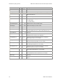
NMS CAS for Natural Call Control Developer's Manual
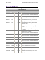
Function
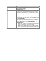
nccBlockCalls
Using NCC service call control
Description and associated events
Blocks calls on a specified line handle. nccBlockCalls may be invoked
from any line state, however, incoming calls will not be blocked until
there are no calls on the line (the line has returned to idle line state).
When using nccBlockCalls, specify the method to be used to block calls.
Two methods are valid:
•
NCC_BLOCK_REJECTALL: Do not answer subsequent calls.
•
NCC_OUT_OF_SERVICE: Place the line out of service.
When the line state has changed to blocking, the application receives
NCCEVN_CALLS_BLOCKED. The value returned with this event contains
the chosen blocking method. The line remains in the blocking state until
nccUnblockCalls is called.
The application may receive NCCEVN_INCOMING_CALL after invoking
nccBlockCalls and before receiving NCCEVN_CALLS_BLOCKED. The
application must handle the incoming call (accept it, answer it, etc.). The
application will not receive the NCCEVN_CALLS_BLOCKED event until it
releases all calls.
If the blocking request fails for some reason, the application receives
NCCEVN_BLOCK_FAILED. The line remains in the current state.
nccUnBlockCalls can be used to cancel a blocking request initiated
using nccBlockCalls. A blocking request can be canceled any time
before NCCEVN_CALLS_BLOCKED is received.
Associated events:
nccDisconnectCall
•
NCCEVN_CALLS_BLOCKED: The block calls request completed
successfully. The line state has changed to blocking.
•
NCCEVN_BLOCK_FAILED: The request to block calls failed. The
event value field contains the reason.
Disconnects a call that is connected to the network. nccDisconnectCall
may also be used to abandon outbound call placement.
The NCC_CAP_DISCONNECT_IN_ANY_STATE bit in the capabilitymask
returned by nccQueryCapability determines the states in which
nccDisconnectCall can be invoked. If the bit is set, nccDisconnectCall
may be invoked in any call state except disconnected. If the bit is
cleared, nccDisconnectCall can only be invoked in the connected call
state.
A disconnected call is no longer active. If no active calls exist on a line,
the line state changes to idle.
Associated event: NCCEVN_CALL_DISCONNECTED indicates that the
disconnect operation has completed successfully and the call has entered
the disconnected call state.
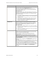
nccGetCallStatus
Retrieves the call control status and stores it in an NCC_CALL_STATUS
structure. Caller ID data is written to the NCC_CALL_STATUS structure.
Applications that require caller ID data can check the calling party's ID by
invoking nccGetCallStatus once NCCEVN_INCOMING_CALL is received,
or by waiting for NCCEVN_CALL_STATUS_UPDATE, with a value code of
NCC_CALL_STATUS_CALLINGADDR.
For more information, refer to the NCC_CALL_STATUS structure on page
40.
Associated events: None.
nccGetExtendedCallStatus
Retrieves protocol-specific status information for a call and stores it in an
NCC_CAS_EXT_CALL_STATUS structure. For more information, refer to
the NCC_CAS_EXT_CALL_STATUS structure on page 42.
Associated events: None.
NMS Communications
31
Using NCC service call control
NMS CAS for Natural Call Control Developer's Manual
Function
nccGetLineStatus
Description and associated events
Retrieves a snapshot of the port status and stores it in an
NCC_LINE_STATUS structure.
Associated events: None.
nccHoldCall
Puts a connected call on hold. There is no call state transition, but a call
on hold is no longer active. Since there are no active calls currently on
the line, the line state changes to idle. The call is on hold only after the
application receives an NCCEVN_CALL_HELD event. The held field in the
NCC_CALL_STATUS structure is set to a non-zero value.
Use nccRetrieveCall to take the call off hold.
Some protocols do not support the capability to put a call on hold. The
application can determine if the protocol supports call hold/retrieve by
examining the NCC_CAP_HOLD_CALL bit in the capabilitymask returned
by nccQueryCapability.
Some protocols allow a call to be put on hold only from the connected
state. The application can determine whether or not a call can be put on
hold from any state by examining the NCC_CAP_HOLD_IN_ANY_STATE
bit in the capabilitymask returned by nccQueryCapability.
Associated events:
32
•
NCCEVN_CALL_HELD: The call hold attempt completed successfully
and the call is now on hold. The line state is now idle.
•
NCCEVN_HOLD_REJECTED: The request to put a call on hold was
rejected. The value field contains information as to why the request
was rejected.
NMS Communications
NMS CAS for Natural Call Control Developer's Manual
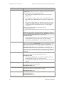
Function
nccPlaceCall
Using NCC service call control
Description and associated events
Places an outbound call to a specified digit string according to call
placement parameters specified in NCC_ADI_PLACECALL_PARMS.
NCCEVN_PLACING_CALL indicates that the call placement operation has
completed successfully and the call has entered the placing call state.
If the application receives NCCEVN_CALL_RELEASED (with an
NCC_RELEASED_FALSE_SEIZURE reason code) instead of
NCCEVN_PLACING_CALL, the line was seized for an incoming call before
glare was resolved, and the TCP has released the outgoing call. The
application should immediately abandon outbound call placement and
handle the incoming call.
The address digits can be sent all at once when invoking the function, or
(with some protocols) digits can be sent in an overlapped fashion.
Associated events:
nccQueryCapability
•
NCCEVN_PLACING_CALL: The TCP has seized an outbound trunk
and resolved glare, and the call has entered the placing call state.
•
NCCEVN_CALL_RELEASED: An incoming call was detected while call
placement was taking place. The TCP has released the outbound call.
The event value field contains NCC_RELEASED_GLARE.
•
NCCEVN_CALL_PROCEEDING: The switch has accepted the call
setup. The receiving side is being rung. The call enters the
proceeding call state.
•
NCCEVN_REMOTE_ALERTING: The remote end is in an alerting state
(for example, is ringing). This event is generated only if the
NCC_REPORT_ALERTING bit is set in the NCC.START.eventmask
parameter.
•
NCCEVN_REMOTE_ANSWERED: Generated at the first positive
indication that the remote party has answered (for example, out-ofband signaling, voice, or modem tone). The event value field
contains the indication type. This event is generated only if the
NCC_REPORT_ANSWERED bit is set in the NCC.START.eventmask
parameter.
•
NCCEVN_CALL_CONNECTED: Both parties are now connected. The
call enters the connected call state.
Queries the capabilities of the protocol on a given line handle. The
application can invoke this function to determine if the current protocol
supports a given feature. nccQueryCapability returns an
NCC_PROT_CAP structure containing capability information for the
protocol.
Associated events: None.
NMS Communications
33
Using NCC service call control
NMS CAS for Natural Call Control Developer's Manual
Function
nccRejectCall
Description and associated events
Rejects an incoming call.
nccRejectCall causes the protocol to reject the incoming call using the
method specified by method. Valid methods are:
•
NCC_REJECT_PLAY_RINGTONE: Play ring tone (only option on
analog trunks).
•
NCC_REJECT_PLAY_BUSY: Plays a busy tone (digital trunks only).
•
NCC_REJECT_PLAY_REORDER: Plays a reorder tone (digital trunks
only).
•
NCC_REJECT_USER_AUDIO: The application generates a recorded
message, or a special information tone. If the remote party hangs
up, the TCP interrupts the application tone or voice file (digital
trunks only).
When a call is being rejected, the application receives
NCCEVN_REJECTING_CALL.
To use the default rejection behavior for the current protocol, set method
to 0.
Note: If the remote party disconnects while the application is rejecting
the call, the application receives NCCEVN_CALL_DISCONNECTED only. In
this case, NCCEVN_REJECTING_CALL is not delivered.
Associated events:
nccReleaseCall
•
NCCEVN_REJECTING_CALL: The reject call operation has completed
successfully and the call has entered the rejecting call state.
•
NCCEVN_CALL_DISCONNECTED: The remote party disconnected.
Releases resources associated with a call in the disconnected state, and
destroys a call handle. nccReleaseCall can only be called when a call is
in the disconnected state. When a call is released, it is completely
destroyed. The application can no longer retrieve call status information.
Associated event: NCCEVN_CALL_RELEASED is returned after the
protocol has performed the network procedures for releasing the call. All
internal resources allocated to the call are released. After the application
receives this event, no more DSP-related events are generated for this
call handle.
nccRetrieveCall
Retrieves a call previously placed on hold with nccHoldCall. The call
becomes active again. The line state changes to active.
Associated events:
nccSendCallMessage
•
NCCEVN_CALL_RETRIEVED: The call retrieve attempt completed
successfully and the call is now no longer on hold.
•
NCCEVN_RETRIEVE_REJECTED: The request to retrieve the call was
rejected.
Pass through mechanism to send a protocol-specific call message directly
to the TCP. Not used for CAS protocols.
Associated events: None.
nccSendDigits
Continues the process of sending digits to place an outbound call (for
protocols that support overlapped sending of digits).
Associated events: None.
nccSendLineMessage
Pass through mechanism to send a protocol-specific line message. Not
used for CAS protocols.
Associated events: None.
34
NMS Communications
NMS CAS for Natural Call Control Developer's Manual
Function
nccStartProtocol
Using NCC service call control
Description and associated events
Prepares an uninitialized line to be used by a protocol to accept and/or
place calls. When invoked, nccStartProtocol returns
NCCEVN_START_PROTOCOL_DONE. This event acknowledges the
protocol startup attempt. The event value field indicates whether the
attempt was successful or not.
Associated event:
NCCEVN_START_PROTOCOL_DONE: Acknowledges the attempt by the
application to start a protocol on a context (line handle). The event value
field indicates if the protocol was started or not. The following reason
codes may be returned:
nccStopProtocol
•
CTA_REASON_FINISHED indicates that the protocol has successfully
been started on a context (line handle). The line state changes from
uninitialized to idle.
•
NCCREASON_OUT_OF_RESOURCES indicates that the protocol has
not been started, because the mediamask parameter is not set
correctly. The line remains in uninitialized line state. See the
hardware documentation for details.
Uninitializes an NCC line. If this command succeeds, the line state
becomes uninitialized. Any calls that are on the line are released. An
NCCEVN_CALL_RELEASED event is generated for each released call.
Then an NCCEVN_STOP_PROTOCOL_DONE event is returned.
Associated events:
nccTransferCall
•
NCCEVN_START_PROTOCOL_DONE: The line state has successfully
changed from idle to uninitialized. It can no longer be used to accept
and/or place calls.
•
NCCEVN_CALL_RELEASED: A call that was on the line was released
before the protocol was stopped.
Completes supervised transfer of two calls. Only one of the two call
handles can be in the connected state and not be on hold. Both calls
must be on the same line (context) handle.
When the transfer is completed, the application should invoke
nccReleaseCall for both call handles to release their resources.
Note: Not all protocols support supervised call transfer. The application
can determine if the protocol supports this state by examining the
NCC_CAP_SUPERVISED_TRANSFER bit in the capabilitymask returned by
nccQueryCapability.
When the transfer is completed, call nccReleaseCall to go back to the
idle state.
Associated event: NCCEVN_CALL_DISCONNECTED should be returned
twice, once for each call. The event indicates that the call is disconnected
(from the point of view of the application). If the call transfer is
successful, the NCC_DIS_TRANSFER reason code is returned with this
event. Other protocol-specific reason codes may be reported for failure to
complete transfer. The CTA_EVENT structure containing this event also
contains the first call handle (callhd1) of the nccTransferCall
invocation.
NMS Communications
35
Using NCC service call control
NMS CAS for Natural Call Control Developer's Manual
Function
nccUnBlockCalls
Description and associated events
Used to release blocking of calls on the specified line (context) handle.
When the line state has changed from blocking to idle, the application
receives NCCEVN_CALLS_UNBLOCKED. It can then receive or place new
calls.
nccUnblockCalls may be used to cancel a previous nccBlockCalls
invocation before the protocol is able to start blocking calls on the
specified line. In this case, the application receives no events.
If the call unblocking request fails for some reason, the application
receives NCCEVN_UNBLOCK_FAILED. The line remains in the blocking
line state.
Associated events:
•
NCCEVN_CALLS_UNBLOCKED: The unblock calls request completed
successfully. The line state has changed to Idle.
•
NCCEVN_UNBLOCK_FAILED: The request to unblock calls failed. The
event value field contains the reason.
The NCC.START.eventmask parameter dictates whether certain informational call
control events are generated. For detailed information about this structure, refer to
the Natural Call Control Service Developer's Reference Manual.
36
NMS Communications
NMS CAS for Natural Call Control Developer's Manual
Using NCC service call control
NCC unsolicited events
Unsolicited events can occur at any time, regardless of the application's current
activities. The following table lists the NCC unsolicited events:
Event
NCCEVN_BILLING_INDICATION
Description
Indicates that a billing indication was detected for an
outbound call. This can be a billing pulse or some more
complex indication. The event value field may contain
the billing units charged, depending upon the protocol
implementation.
This event is generated only if the
NCC_REPORT_BILLING bit is set in the
NCC.START.eventmask parameter.
NCCEVN_CALL_CONNECTED
Indicates that a call has reached the connected call
state. The event value field contains the reason for
connection.
NCCEVN_CALL_DISCONNECTED
This event indicates one of the following:
•
The application invoked nccDisconnectCall.
•
The remote party hung up. This event can occur in
almost any call state.
•
The call is inbound, and the application rejected the
call.
•
The call is outbound, the remote party answered,
and the call failed to meet the criteria specified by
the NCC_ADI_PLACECALL_PARMS connectmask
passed with nccPlaceCall, or met the criteria
specified by the disconnectmask.
The event value field contains the reason that the call
was disconnected.
A disconnected call is no longer considered active. If
there are no active calls on a line (all calls on the line
are either held or disconnected), the line state returns to
idle.
Disconnected calls should be released using
nccReleaseCall.
NMS Communications
37
Using NCC service call control
Event
NCCEVN_CALL_HELD
NMS CAS for Natural Call Control Developer's Manual
Description
Indicates that a call has been placed on hold, either by
the application or by a remote party. When a call is
placed on hold, no call state change occurs. However, a
call on hold is not considered active. If there are no
active calls on a line (any calls on the line are either held
or disconnected) the line state returns to idle.
Call holding is not supported by all protocols. The
NCC_CAP_HOLD_CALL indicator in the capabilitymask
returned by nccQueryCapability indicates if the current
protocol supports this event or not.
Ordinarily, a call can only be placed on hold in the
connected call state. However, if the
NCC_CAP_HOLD_IN_ANY_STATE indicator is set in the
capabilitymask for the protocol, the application can place
a call on hold regardless of the call state.
The application can call nccGetCallStatus to determine
whether a call is on hold or not. If a call is on hold, the
held attribute in the NCC_CALL_STATUS structure
returned for that call contains a non-zero value.
NCCEVN_CALL_PROCEEDING
Indicates that the switch has accepted the call setup
request, and is in the process of attempting to ring the
receiving end. Call progress analysis is begun. The call
state changes to proceeding.
NCCEVN_CALL_RETRIEVED
Indicates that a call on hold was retrieved, either by the
application or by a remote party. The call is now active.
Since there is an active call on the line, the line state
changes to active.
Call hold/retrieve is not supported by all protocols.
NCC_CAP_HOLD_CALL in the capabilitymask returned
by nccQueryCapability indicates if the current protocol
supports this capability.
The application can call nccGetCallStatus to determine
whether a call is on hold. If a call is on hold, the held
attribute in the NCC_CALL_STATUS structure returned
for that call contains a non-zero value.
If an automatic transfer fails,
NCCEVN_CALL_RETRIEVED is returned, with a value
field containing one of the NCC_DIS_xxx reason codes
indicating why the transfer failed.
NCCEVN_CALL_STATUS_UPDATE
If call status information changes, the application
receives this event. The event value field indicates the
type of information that was changed. The application
can then invoke nccGetCallStatus to get the updated
information.
This event can occur in any call state, as long as the line
state is active. It is generated only if the
NCC_REPORT_STATUSINFO bit is set in the
NCC.START.eventmask parameter.
NCCEVN_CAPABILITY_UPDATE
38
The application receives this event when the capabilities
of a protocol change. The event value field indicates the
capability that changed. The application can call
nccQueryCapability to determine the current set of
protocol capabilities.
NMS Communications
NMS CAS for Natural Call Control Developer's Manual
Using NCC service call control
Event
Description
NCCEVN_EXTENDED_CALL_STATUS_UPDATE
The application receives this event when protocolspecific call status information changes. The event value
field indicates the kind of information that was changed.
The application can then call
nccGetExtendedCallStatus to retrieve this
information.
This event is generated only if the
NCC_REPORT_STATUSINFO bit is set in the
NCC.START.eventmask parameter.
NCCEVN_INCOMING_CALL
Indicates that the NCC service detected an incoming call
and all necessary call information (for example, digits)
has been gathered. The call is now in the incoming call
state. At this point, the application decides whether to
accept, answer, or reject the call.
NCCEVN_LINE_IN_SERVICE
Indicates that an out-of-service line (a line in out-ofservice line state) was placed in service. It is now in idle
line state.
NCCEVN_LINE_OUT_OF_SERVICE
Indicates that a line was taken out of service. The event
value field indicates the reason for taking the line out of
service.
NCCEVN_PROTOCOL_ERROR
An error condition occurred. The call may be in an
unusable state.
NCCEVN_PROTOCOL_EVENT
The protocol implementation generated an unsolicited
event.
NCCEVN_RECEIVED_DIGIT
Indicates that a call address or subaddress digit has
been received from the network. The application may
receive several of these events, as digits are received in
an overlapped fashion for an incoming call. The value
field contains the digit. When the first digit is received,
the call state changes from seizure to receiving digits.
The call remains in this state until
NCCEVN_INCOMING_CALL is received.
This event is generated only if the NCC_REPORT_DIGITS
bit is set in the NCC.START.eventmask parameter.
NCCEVN_REJECTING_CALL
Either of the following has occurred:
•
The application has invoked nccRejectCall to reject
an incoming call.
•
The application has failed to accept, answer, or
reject an incoming call within the period of time
specified by the NCC.START.waitforPCtime
parameter.
The call enters the rejecting call state. The event value
field contains the reason why the call was rejected.
NCCEVN_SEIZURE_DETECTED
NMS Communications
Indicates that NCC has detected an incoming call. A call
handle is created for the call. The call handle may now
be used for all subsequent operations for this call. The
new call begins in the seizure call state.
39
Using NCC service call control
NMS CAS for Natural Call Control Developer's Manual
Retrieving call information
The following information is useful when developing applications that retrieve status
information about existing calls:
•
NCC functions for retrieving call information
•
NCC_CALL_STATUS structure
•
NCC_CAS_EXT_CALL_STATUS structure
NCC functions for retrieving call information
To get call status information, the application can use the following NCC functions:
Function
Description
nccGetCallStatus
Returns an NCC_CALL_STATUS structure containing basic information
about the call, such as the DID and ANI information, and whether or
not the call is on hold.
nccGetExtendedCallStatus
Returns an NCC_CAS_EXT_CALL_STATUS structure containing other
information about the call. For NMS CAS, this information may include
the user and toll category, and billing rate. The types of information
received with this function differ from protocol to protocol.
Either of these synchronous functions can be invoked in any call state, as long as the
line is in an active line state.
An application may also receive the unsolicited events
NCCEVN_CALL_STATUS_UPDATE or NCCEVN_EXTENDED_CALL_STATUS_UPDATE
while a particular call is still in progress. These events indicate a change in the status
for the specified call. The application can examine the value field of the event for
information about the type of status change that has occurred for the specific call.
Then the application can invoke nccGetCallStatus or nccGetExtendedCallStatus
to retrieve structures (NCC_CALL_STATUS or NCC_CAS_EXT_CALL_STATUS) that
provide specific information about the call's status.
NCC_CALL_STATUS structure
nccGetCallStatus is a protocol independent NCC function that returns the following
NCC_CALL_STATUS structure:
typedef struct
{
DWORD size ;
DWORD state;
char calledaddr [NCC_MAX_DIGITS+1];
char callingaddr[NCC_MAX_DIGITS+1];
char callingname[NCC_MAX_CALLINGNAME];
DWORD pendingcmd;
DWORD held;
DWORD direction;
CTAHD linehd;
} NCC_CALL_STATUS;
40
NMS Communications
NMS CAS for Natural Call Control Developer's Manual
Using NCC service call control
The NCC_CALL_STATUS structure contains the following fields:
Field
Description
size
Number of bytes written at the address pointed to by status.
state
Current call state. Valid states are:
NCC_CALLSTATE_INVALID
NCC_CALLSTATE_SEIZURE
NCC_CALLSTATE_RECEIVING_DIGITS
NCC_CALLSTATE_INCOMING
NCC_CALLSTATE_ACCEPTING
NCC_CALLSTATE_ANSWERING
NCC_CALLSTATE_REJECTING
NCC_CALLSTATE_CONNECTED
NCC_CALLSTATE_DISCONNECTED
NCC_CALLSTATE_OUTBOUND_INITIATED
NCC_CALLSTATE_PLACING
NCC_CALLSTATE_PROCEEDING
calledaddr
For inbound calls, the address of the requested number if provided (for example, DID).
callingaddr
For inbound calls, the address of the caller, if provided (for example, caller ID, ANI).
pendingcmd
The last call control command issued that has not yet been acknowledged by the board.
This field is set when a call control command is sent to the board, and cleared on the next
event that corresponding to the acknowledgment of the pending command.
Possible values are:
(0) No command pending.
NCC_PENDINGCMD_ACCEPT_CALL
NCC_PENDINGCMD_ANSWER_CALL
NCC_PENDINGCMD_AUTOMATIC_TRANSFER
NCC_PENDINGCMD_DISCONNECT_CALL
NCC_PENDINGCMD_HOLD_CALL
NCC_PENDINGCMD_PLACE_CALL
NCC_PENDINGCMD_REJECT_CALL
NCC_PENDINGCMD_RELEASED_CALL
NCC_PENDINGCMD_RETRIEVE_CALL
NCC_PENDINGCMD_TRANSFER_CALL
NCC_PENDINGCMD_SET_BILLING
held
Set to non-zero value when a call is held.
direction
Indicates inbound or outbound call. Possible values are:
NCC_CALL_INBOUND
NCC_CALL_OUTBOUND
linehd
Line (context) handle on which the call resides.
Note: NCC_CALL_STATUS fields are not guaranteed to be filled during call setup.
The values of these fields depend on the information associated with the incoming
call, and on the protocol used to set up the call.
NMS Communications
41
Using NCC service call control
NMS CAS for Natural Call Control Developer's Manual
NCC_CAS_EXT_CALL_STATUS structure
nccGetExtendedCallStatus returns the NCC_CAS_EXT_CALL_STATUS structure:
typedef struct
{
DWORD size;
char ANIpresentation;
char redirectingaddr [NCC_MAX_DIGITS+1];
char redirectingreason;
char usercategory;
char tollcategory;
char carrierid [NCC_MAX_DIGITS+1];
WORD billingrate;
}NCC_CAS_EXT_CALL_STATUS;
/*
/*
/*
/*
/*
/*
/*
Set if the ANI presentation is restricted
Contains redirecting address information
Contains the reason for redirection
Contains the user category
Contains the toll category
Contains the carrier ID information
Information passed with BILLING_SET event
*/
*/
*/
*/
*/
*/
*/
The NCC_CAS_EXT_CALL_STATUS structure contains the following fields:
Field
Protocols that
use the field
Description
ANIpresentation
MFC, EAM
Set if ANI presentation is restricted (caller ID information is
restricted).
redirectingaddr
EUC (Sweden),
LPS (with caller
ID)
Redirecting number information (if the call has been redirected
from another terminal).
redirectingreason
LPS (with caller
ID)
Reason for call redirection (for example, busy, universal, or
unanswered).
usercategory
MFC, EAM, R15,
LPS (with caller
ID)
Either the type of the calling party (for example, normal
subscriber, operator, pay phone), or the type of call (protocolspecific).
tollcategory
MFC, EAM, LPS
(with caller ID)
Generally the same as usercategory for MFC and EAM (it might
be different for certain countries using the MFC-R2 protocol, if
supported). For LPS, it is filled with the call qualifier information.
carrierid
FGD, LPS (with
caller ID)
Carrier ID information. For LPS, it contains the first called line
identity information.
billingrate
MFC, EAM
Indication if the current call is billed or free (for CAS protocols,
the actual cost of an outbound call is calculated by counting
billing pulses, if the network offers this service).
Note: Only a subset of NCC_CAS_EXT_CALL_STATUS fields are filled depending on
the protocol used.
To verify whether specific fields are supported in your country, refer to:
42
•
BellCore caller ID data on page 173
•
NTT (Japan) caller ID data on page 176
•
ETSI (France) caller ID data on page 174
NMS Communications
NMS CAS for Natural Call Control Developer's Manual
Using NCC service call control
nccPlaceCall and specifying extended information
With certain NMS CAS protocols, when an application attempts to place a call with
nccPlaceCall, extended information can be sent with the call placement request.
This information is included in the CAS_PLACECALL_EXT structure which is a
component of the NCC_ADI_CAS_PARMS structure:
typedef struct
{
DWORD
size;
char
ANIpresentation;
BYTE
redirectingreason;
WORD
satellitecircuit;
char
redirectingaddr[33];
char
carrierid[33];
char
pad2[2];
INT16
usercategory;
INT16
tollcategory;
char
datetime[8];
char
callingname[32];
} CAS_PLACECALL_EXT;
In the function call, the NCC_ADI_CAS_PARMS structure is referenced using the void
*protcallparms argument.
The CAS_PLACECALL_EXT structure contains the following fields:
Field
Protocols that use
the field
Description
size
All
Size of this structure.
ANIpresentation
MFC, EAM, STA
Set this parameter if ANI presentation is restricted (that is,
caller ID information is restricted).
redirectingreason
LPS (with caller ID)
Reason for call redirection (for example, busy, universal, or
unanswered).
satellitecircuit
MFC
Set this parameter if there is a satellite link in the circuit.
redirectingaddr
EUC, STA
Redirecting number information (if the call has been
redirected from another terminal).
carrierid
FGD, STA
Carrier ID information.
usercategory
MFC, LPS (with caller
ID), EAM, R15, STA
The type of the calling party (for example, normal
subscriber, operator, pay phone), or the type of call
(protocol-specific).
tollcategory
MFC, EAM, STA
Generally the same as usercategory, if supported. It can be
different for certain countries using the MFC-R2 protocol.
datetime
STA
Date and time as MMDDhhmm.
callingname
STA
Calling party name.
NMS Communications
43
Using NCC service call control
NMS CAS for Natural Call Control Developer's Manual
nccDisconnectCall and specifying extended information
With certain NMS CAS protocols, when an application attempts to disconnect a call
with nccDisconnectCall, extended information can be sent with the call disconnect
request. This information is included in the CAS_DISCONNECT_EXT structure which
is a component of the NCC_ADI_CAS_PARMS structure:
typedef struct
{
DWORD
size;
WORD
cause;
WORD
pad;
} CAS_DISCONNECT_EXT;
/* size of this structure
/* disconnect cause
*/
*/
In the function call, the NCC_ADI_CAS_PARMS structure is referenced using the void
*protcallparms argument.
The CAS_DISCONNECT_EXT structure contains the following fields:
Field
Protocols that use the
field
Description
size
All
Size of this structure.
cause
WNK, STA
Disconnect cause. Determines the call progress tone sent to an offhook, disconnected party.
nccRejectCall and specifying extended information
With certain NMS CAS protocols, when an application attempts to reject a call with
nccRejectCall, extended information can be sent with the call reject request. This
information is included in the CAS_REJECT_EXT structure which is a component of
the NCC_ADI_CAS_PARMS structure:
ttypedef struct
{
DWORD
size;
WORD
cause;
WORD
pad;
}
CAS_REJECT_EXT;
/* size of this structure
/* reject cause
*/
*/
In the function call, the NCC_ADI_CAS_PARMS structure is referenced using the void
*protcallparms argument.
The CAS_REJECT_EXT structure contains the following fields:
Field
Protocols that use
the field
Description
size
All
Size of this structure.
cause
WNK, MFC
Reject cause. For MFC, this can be used to determine the Group B
tone used to reject the call.
44
NMS Communications
NMS CAS for Natural Call Control Developer's Manual
Using NCC service call control
Determining the capabilities of a protocol
With the NCC service, an application can call nccQueryCapability to determine the
capabilities of a protocol. nccQueryCapability returns a capabilitymask.
For more information, refer to NMS CAS TCP call control capabilities on page 45.
Receiving billing pulses
If the network provides the capability of receiving billing pulses, an outbound call
receives billing pulses during the connected state. These are brief variations in the
state of the signaling bits that signal that a unit of cost has been billed to the call.
The actual price of a unit of cost changes from network to network, as does the
frequency with which billing pulses are received.
An application placing outbound calls can set the bit NCC_REPORT_BILLING in the
NCC.START.eventmask parameter to enable the reception of billing pulse events.
These are presented as NCCEVN_BILLING_INDICATION events by Natural Access.
The application can then count the events to calculate the cost of the call.
NMS CAS TCP call control capabilities
This topic provides an overview of the NCC capabilities associated with individual
NMS CAS TCPs. For more information, refer to the Natural Call Control Service
Developer's Reference Manual and to NMS CAS protocols on page 10.
AP2, EAM, EL7, EUC, EUC/SWE, FGD, GDS, and LPS
The following table shows the capabilities that the indicated protocols support:
Capability
AP2
EAM
EL7
EUC
EUC/
SWE
FGD
GDS
LPS
NCC_CAP_ACCEPT_CALL
Yes
Yes
Yes
Yes
Yes
Yes
Yes
Yes
NCC_CAP_SET_BILLING
No
Yes
No
No
No
No
No
No
NCC_CAP_OVERLAPPED_SENDING
Yes
Yes
No
Yes
Yes
Yes
No
No
NCC_CAP_HOLD_CALL
No
No
Yes
No
No
No
Yes
Yes
NCC_CAP_SUPERVISED_TRANSFER
No
No
Yes
No
No
No
Yes
Yes
NCC_CAP_AUTOMATIC_TRANSFER
No
No
Yes
No
No
No
Yes
Yes
NCC_CAP_EXTENDED_CALL_STATUS
No
Yes
No
No
Yes
Yes
No
Yes
NCC_CAP_SEND_CALL_MESSAGE
No
No
No
No
No
No
No
No
NCC_CAP_SEND_LINE_MESSAGE
No
No
No
No
No
No
No
No
NCC_CAP_HOLD_IN_ANY_STATE
No
No
No
No
No
No
No
No
NCC_CAP_DISCONNECT_IN_ANY_STATE
No
No
No
No
No
No
No
No
NCC_CAP_MEDIA_IN_SETUP
Yes
Yes
No
Yes
Yes
Yes
No
No
NCC_CAP_CALLER_ID
No
Yes
No
No
Yes
Yes
No
Yes
Note: The NCC_CAP_CALLER_ID capability is supported for France, Japan, and the
US if the NCC.X.ADI_LPS.cidsupport parameter is set to 1.
NMS Communications
45
Using NCC service call control
NMS CAS for Natural Call Control Developer's Manual
MELCAS, NEC, MFC, MFS, OPS, R15, SS5, STA, and WNK
The following table shows the capabilities that the indicated protocols support:
Capability
MELCAS
NEC
MFC
MFS
OPS
R15
SS5
STA
WNK
NCC_CAP_ACCEPT_CALL
Yes
Yes
Yes
Yes
Yes
Yes
Yes
Yes
Yes
NCC_CAP_SET_BILLING
No
No
Yes
No
No
No
No
No
No
NCC_CAP_OVERLAPPED_SENDING
No
No
Yes
Yes
No
Yes
Yes
No
Yes
NCC_CAP_HOLD_CALL
Yes
Yes
No
No
Yes
No
No
Yes
Yes
NCC_CAP_SUPERVISED_TRANSFER
Yes
Yes
No
No
Yes
No
No
No
Yes
NCC_CAP_AUTOMATIC_TRANSFER
Yes
Yes
No
No
Yes
No
No
No
Yes
NCC_CAP_EXTENDED_CALL_STATUS
No
No
Yes
Yes
No
Yes
No
No
No
NCC_CAP_SEND_CALL_MESSAGE
No
No
No
No
No
No
No
No
No
NCC_CAP_SEND_LINE_MESSAGE
No
No
No
No
No
No
No
No
No
NCC_CAP_HOLD_IN_ANY_STATE
No
No
No
No
No
No
No
No
No
NCC_CAP_DISCONNECT_IN_ANY_STATE
No
No
No
No
No
No
No
No
No
NCC_CAP_MEDIA_IN_SETUP
No
Yes
Yes
Yes
No
Yes
Yes
Yes
Yes
NCC_CAP_CALLER_ID
Yes
No
Yes
Yes
Yes
Yes
No
No
Yes
46
NMS Communications
5
NCC parameters
NCC call control parameters
The behavior of many NCC functions, and of the operating protocol, is controlled by
parameters. These parameters are grouped together into structures. Each parameter
structure has a set of default values that is sufficient for many configurations. You
can modify the parameters to:
•
Enable or disable function features.
•
Adapt the function for exceptional configurations.
For example, when recording voice data, you can alter the function's behavior by
modifying any of the record parameters that specify:
•
Any subset of DTMF keys entered by the telephone caller that abort the
function.
•
Gain applied to the input signal.
•
An initial timeout, which defines the time during which the caller must start
speaking before the operation terminates.
•
The amount of silence after a caller has stopped speaking before the
operation terminates.
•
Record-sync prompt frequency, amplitude, and duration.
•
Automatic gain control settings.
The following parameters are available for NMS CAS TCPs:
•
NCC.X.ADI_START
•
NCC.X.ADI_START.cleardown
•
NCC.X.ADI_START.dial
•
NCC.X.ADI_START.dtmfdet
•
NCC.X.ADI_START.echocancel
•
NCC.X.ADI_PLACECALL
•
NCC.X.ADI_PLACECALL.callprog
Refer to NMS CAS TCP call control capabilities on page 45 for more information.
NMS Communications
47
NCC parameters
NMS CAS for Natural Call Control Developer's Manual
NCC.X.ADI_START
The following tables describes NCC.X.ADI_START parameters:
NCC.X.ADI_START
Dependent function: nccStartProtocol
Field
Type
mediamask
DWORD
Default
Units
Description
0x001F
mask
Controls which functions will be running or reserved when
the call enters the connected (conversation) state. (The
NOCC protocol enters this state immediately.) Reserved
indicates that the DSP MIPS have been committed to the
operation before the operation has actually started. The
application must reserve DSP resources in advance by
using this parameter for DTMF detection, silence
detection, cleardown detection, and echo cancellation.
A value can be formed by using the OR operator with any
of the following bit masks or by using one of the specified
constants:
48
•
NCC_RESERVE_DTMF (0x0001): Reserve DTMF
detection (not used for QX boards)
•
NCC_RESERVE_SILENCE (0x0002): Reserve
cleardown detector (not used for QX boards)
•
NCC_RESERVE_CLEARDOWN (0x0004): Reserve
DTMF detection (not used for QX boards)
•
NCC_AUTO_DTMF (0x0008): Start DTMF detection
•
NCC_AUTO_ECHO (0x0010): Start echo canceller
•
NCC_ALL_MEDIA (0x001F):
(NCC_RESV_CLEARDOWN|
NCC_RESV_SILENCE|
NCC_RESV_DTMF|
NCC_RESV_AUTO_DTMF|
NCC_RESV_AUTO_ECHO)
•
NCC_ACCEPT_DTMF (0x100): DTMF detection in
accept
NMS Communications
NMS CAS for Natural Call Control Developer's Manual
NCC parameters
NCC.X.ADI_START.cleardown
The following table describes NCC.X.ADI_START.cleardown parameters:
NCC.X.ADI_START.cleardown
Dependent function: nccStartProtocol
Field
Type
bandw1
DWORD
40
Hz
Bandwidth for first frequency of the cleardown detector.
Valid range is 20 to 800.
bandw2
DWORD
40
Hz
Bandwidth for second frequency. Valid range is 20 to
800.
freq1
DWORD
350
Hz
First frequency to detect. Valid range is 1 to 4000.
freq2
DWORD
440
Hz
Second frequency to detect, or 0 if detecting single
frequency. Valid range is 1 to 4000.
maxofftime
DWORD
0
ms
Maximum time tone may be OFF to qualify. For
continuous tones, this parameter is ignored. For
cadenced tones, the count is reset if the interval
between any two tones is longer than this time. Valid
range is 0 to 32767.
maxontime
DWORD
0
ms
Maximum time tone must be ON to qualify. For
continuous tones, this parameter is ignored. For
cadenced tones, the count is reset if any tone is longer
than this time. Valid range is 0 to 32767.
minofftime
DWORD
0
ms
Minimum time tone must be OFF to qualify. For
continuous tones, this parameter is ignored. For
cadenced tones, the count is reset if the interval
between any two tones is shorter than this time. Valid
range is 0 to 32767.
minontime
DWORD
0
ms
Minimum time tone must be ON to qualify. For
continuous tones, this parameter is ignored. For
cadenced tones, the count is reset if any tone is shorter
than this time. Valid range is 0 to 32767.
qualampl
INT32
dBm
Minimum signal level recognized as a hang-up tone.
Valid AG and CG range is -51 to -15. Valid QX range is 48 to 0.
qualtime
DWORD
1000
ms
Minimum duration of tone before a hang-up is
recognized. The valid range is 0 to 32767. qualtime is
ignored if tonecount is non-zero (cadenced tones).
reflevel
DWORD
0xB000
IDU
Do not modify.
reserved
DWORD
0
internal
Do not modify.
tonecount
DWORD
0
integer
Minimum number of cadenced tones detected before
reporting the cleardown event. For continuous tones,
set this parameter to 0.
NMS Communications
Default
-28
Units
Description
49
NCC parameters
NMS CAS for Natural Call Control Developer's Manual
NCC.X.ADI_START.dial
The following table describes NCC.X.ADI_START.dial parameters:
NCC.X.ADI_START.dial
Dependent functions: nccStartProtocol
Field
Type
breaktime
DWORD
60
ms
Break (on-hook) duration for dial pulses.
Valid AG and CG range is 0 to 30000. Valid QX range
is 0 to 32767.
dialtonewait
DWORD
5000
ms
Maximum time to wait for dial tone (applies only to
the semicolon (;) character). Valid range is 0 to
65535.
dtmfampl1
INT32
-6
dBm
Amplitude of the low frequency component of the
DTMF pair. Valid AG and CG range is -54 to -3. Valid
QX range is -90 to 0.
dtmfampl2
INT32
-4
dBm
Amplitude of the high frequency component of the
DTMF pair. Valid AG and CG range is -54 to -3. Valid
QX range is -90 to 0.
dtmfofftime
DWORD
80
ms
Duration of the silence time between each digit. Valid
AG and CG range is 0 to 65534. Valid QX range is 0
to 2047.
dtmfontime
DWORD
80
ms
Duration of each DTMF or MF digit.
Valid AG and CG range is 0 to 65534. Valid QX range
is 0 to 2047.
flashtime
DWORD
500
ms
Amount of time to assert the on-hook signaling
pattern for a flash (!) character.
Valid AG and CG range is 0 to 65535. Valid QX range
is 0 to 32767.
interpulse
DWORD
700
ms
Inter-digit time for pulsed dialing.
Valid AG and CG range is 0 to 30000. Valid QX range
is 0 to 32767.
longpause
DWORD
5000
ms
Amount of delay associated with the period (.)
character. Valid range is 0 to 65535.
maketime
DWORD
40
ms
Make (off-hook) duration for dial pulses.
Valid AG and CG range is 0 to 30000. Valid QX range
is 0 to 32767.
method
DWORD
0
mask
reserved
DWORD
0
internal
shortpause
DWORD
2000
ms
Amount of delay associated with the comma (,)
character. Valid range is 0 to 65535.
tonebandw1
DWORD
40
Hz
Bandwidth of the first frequency of the dial tone
detector. Valid AG and CG range is 20 to 800. Valid
QX range is 40 to 2000.
tonebandw2
DWORD
40
Hz
Bandwidth of the second frequency of the dial tone
detector. Valid AG and CG range is 20 to 800. Valid
QX range is 40 to 2000.
50
Default
Units
Description
Type of signaling: 0=DTMF, 1=Pulse, 2=MF (US).
Do not modify.
NMS Communications
NMS CAS for Natural Call Control Developer's Manual
NCC parameters
NCC.X.ADI_START.dial
Dependent functions: nccStartProtocol
Field
Type
tonefreq1
DWORD
350
Hz
First (or only) dial tone frequency.
Valid AG and CG range is 330 to 3600. Valid QX
range is 1 to 4000.
tonefreq2
DWORD
440
Hz
Second dial tone frequency. Set this to 0 to detect a
single frequency. Valid AG and CG range is 330 to
3600. Valid QX range is 1 to 4000.
tonequalampl
INT32
-28
dBm
Minimum broadband signal amplitude to qualify for
dial tone detection. Valid AG and CG range is -40 to
0. Valid QX range is -48 to 0.
tonequaltime
DWORD
50
ms
Minimum duration of a qualified tone to be
considered dial tone. Valid range is 0 to 32767.
tonereflevel
DWORD
0xb000
IDU
Do not modify.
tonetotaltime
DWORD
0
ms
Total time interrupted dialtone must be present.
NMS Communications
Default
Units
Description
51
NCC parameters
NMS CAS for Natural Call Control Developer's Manual
NCC.X.ADI_START.dtmfdet
The following table describes NCC.X.ADI_START.dtmfdet parameters:
NCC.X.ADI_START.dtmfdet
Dependent function: nccStartProtocol
Field
Type
Default
Units
Description
columnfour
DWORD
1
mask
Flag that indicates whether to detect the A, B, C, and D
DTMF digits. Set this to 1 to detect these, or 0 to ignore
them.
offqualampl
INT32
-45
dBm
Minimum signal required to maintain recognition of a
DTMF signal once recognition has started.
Valid AG and CG range is -51 to -15. Not used for QX
boards.
offqualtime
DWORD
40
ms
Minimum duration of absence of a recognized DTMF
signal before an end-of-digit event is emitted. Valid AG
and CG range is 5 to 32767. Valid QX range is 0 to
32766.
offthreshold
DWORD
0x92e0
IDU
Do not modify.
onqualampl
INT32
-39
dBm
Minimum signal level recognized as a DTMF signal.
Valid AG and CG range is -51 to -15. Not used for QX
boards.
onqualtime
DWORD
50
ms
Minimum duration of a recognized DTMF signal before a
digit event is emitted. Valid AG and CG range is 22 to
32767. Valid QX range is 0 to 32766.
onthreshold
DWORD
0xcab0
IDU
Do not modify.
52
NMS Communications
NMS CAS for Natural Call Control Developer's Manual
NCC parameters
NCC.X.ADI_START.echocancel
The following table describes NCC.X.ADI_START.echocancel parameters:
NCC.X.ADI_START.echocancel
Dependent functions: nccStartProtocol
Field
Type
Default
Units
Description
adapttime
DWORD
0
ms
Echo canceller adaptation time for MODE=2. The valid
AG and CG range is 100 to 1000. Smaller values require
more DSP processing power. Not used for QX boards.
filterlength
DWORD
0
ms
Filter length of echo canceller for MODE=2. Valid range
is 2 to 20. Greater values require more DSP processing
power.
gain
INT32
0
dB
Amount of amplification applied to echo cancelled
output. Valid AG and CG range is -54 to 24. Done by the
AGC module for QX boards.
mode
DWORD
0
integer
Controls echo canceller operation:
A value can be formed by using the OR operator with
any of the following bit masks or by using one of the
specified constants:
NCC_ECHOCANCEL_DEFAULT (1): Choose the default
length and adapt time based on board type. (For AG
4000/C and AG 4040/C boards, the default is for no echo
cancel.) For more information, see the ADI Service
Developer's Reference Manual.
NCC_ECHOCANCEL_CUSTOM (2): Use specified length
and adapt time.
Default = 0: No echo cancellation.
predelay
DWORD
NMS Communications
0
ms
Output sample delay. Valid range is 0 to 9.
53
NCC parameters
NMS CAS for Natural Call Control Developer's Manual
NCC.X.ADI_PLACECALL
The following table describes NCC.X.ADI_PLACECALL parameters:
NCC.X.ADI_PLACECALL
Dependent functions: nccPlaceCall, nccAutomaticTransfer
Field
Type
Default
Units
Description
connectmask
DWORD
0x0103
mask
Controls which network events cause an outgoing
call to transition to the connected state. A value can
be formed by using the OR operator with any of the
following bit masks:
54
•
NCC_CON_ON_SIGNAL (0x0001): Out-of-band
signal
•
NCC_CON_ON_VOICE_BEGIN (0x0002): Voice
detected
•
NCC_CON_ON_VOICE_MEDIUM (0x0004):
Medium length voice
•
NCC_CON_ON_VOICE_LONG (0x0008): Long
voice
•
NCC_CON_ON_VOICE_EXTENDED (0x0010):
Extended voice
•
NCC_CON_ON_VOICE_END (0x0020): Voice
ended
•
NCC_CON_RING_QUIT (0x0080): Ring ended
•
NCC_CON_ON_CED (0x0100): Modem detected
•
NCC_CON_ON_DIALTONE (0x0200): Dial tone
•
NCC_CON_ON_SIT (0x0400): SIT detected
•
NCC_CON_ON_RING_BEGIN (0x0800): Connect
immediately
•
NCC_CON_ON_PROCEEDING (0x8000): Connect
immediately
NMS Communications
NMS CAS for Natural Call Control Developer's Manual
NCC parameters
NCC.X.ADI_PLACECALL
Dependent functions: nccPlaceCall, nccAutomaticTransfer
Field
Type
Default
Units
Description
disconnectmask
DWORD
0x0040
mask
Controls which network events cause an outgoing
call to disconnect (not complete). A value can be
formed by using the OR operator with any of the
following bit masks:
NMS Communications
•
NCC_DIS_ON_VOICE_BEGIN (0x0002): Voice
detected
•
NCC_DIS_ON_VOICE_MEDIUM (0x0004):
Medium length voice
•
NCC_DIS_ON_VOICE_LONG (0x0008): Long
voice
•
NCC_DIS_ON_VOICE_EXTENDED (0x0010):
Extended voice
•
NCC_DIS_ON_VOICE_END (0x0020): Voice
ended
•
NCC_DIS_ON_TIMEOUT (0x0040): Call progress
timeout
•
NCC_DIS_ON_RING_QUIT (0x0080): Call
progress ring quit
•
NCC_DIS_ON_CED (0x0100): Dial tone
•
NCC_DIS_ON_RING_BEGIN (0x0800): Call
progress ring begin
55
NCC parameters
NMS CAS for Natural Call Control Developer's Manual
NCC.X.ADI_PLACECALL.callprog
The following table describes NCC.X.ADI_PLACECALL.callprog parameters:
NCC.X.ADI_PLACECALL.callprog
Dependent functions: nccPlaceCall, nccAutomaticTransfer
Field
Type
Default
Units
Description
busycount
DWORD
4
count
Number of non-precise busy tones that must occur
before busy or fast busy is reported. Valid range is 1
to 32767.
leakagetime
DWORD
8
ms
Do not modify.
maxbusy
DWORD
1500
ms
Threshold time defining the total time period (on
time plus off time) for distinguishing between slow
busy and ringing tone. Valid range is 0 to 32767.
maxreorder
DWORD
700
ms
Threshold time defining the total time period (on
time plus off time) for distinguishing between fast
busy (reorder) and slow busy. Valid range is 0 to
32767.
maxring
DWORD
3000
ms
Maximum duration of a tone to distinguish a ringing
tone from a dial tone. Valid range is 0 to 32767.
maxringperiod
DWORD
8000
ms
Length of time of the last ringing tone plus the
silence that follows, before call progress reports a
ringing-ended event. Valid range is 0 to 32767.
noiselevel
DWORD
0x14000
IDU
Do not modify.
precmask
DWORD
7
mask
Mask to control which precise detectors to run. A
value can be formed by using the OR operator with
any of the following bit masks:
•
NCC_CPMSK_PRECISE_CED (0x0001): CED tone
modem
•
NCC_CPMSK_PRECISE_SIT (0x0002): SIT
•
NCC_CPMSK_PRECISE_BUSY (0x0004): Busy
and reorder tone (US)
•
NCC_CPMSK_PRECISE_425 (0x0008) 425 Hz
tone (busy and reorder tone, non-US)
•
NCC_CPMSK_PRECISE_SITEXT (0x0010): SIT
type reporting
•
NCC_CPMSK_PRECISE_TDD (0x0020): TDD/TTY
device
•
NCC_CPMSK_PRECISE_NU (0x0040):
Unassigned number
Only three of the four detectors can run concurrently.
If all four detectors are specified, busy and reorder
tones are determined by cadence alone, and only the
SIT, CED, and TDD/TTY detectors are enabled.
Busy and reorder tone (bit value 0x0004) and the
425 Hz tone selection (bit value 0x0008) are
mutually exclusive. If you choose both, only the 425
Hz filter takes effect.
56
NMS Communications
NMS CAS for Natural Call Control Developer's Manual
NCC parameters
NCC.X.ADI_PLACECALL.callprog
precqualtime
DWORD
150
ms
Precise tone qualification time. All precise tones must
be longer than this value to qualify. Valid range is 0
to 32767.
qualtonetime1
DWORD
60
ms
Do not modify.
qualtonetime2
DWORD
80
ms
Do not modify.
qualvoicetime1
DWORD
60
ms
Do not modify.
qualvoicetime2
DWORD
60
ms
Do not modify.
ringcount
DWORD
7
count
The number of ring tones that must occur before
NO_ANSWER is reported. Valid range is 1 to 32767.
silencelevel
INT32
-40
dBm
Maximum signal level that is considered to be
silence. Valid AG and CG range is -46 to -34. Valid
QX range is -45 to 0.
silencetime
DWORD
1500
ms
Minimum length of a silent period after voice is
detected before call progress reports a voice-ended
event.
stopmask
DWORD
0
mask
Mask to control which events cause call progress to
stop. A value can be formed by using the OR
operator with any of the following bit masks or by
using one of the specified constants:
•
NCC_CPSTOP_ON_RINGTONE (0x0000): Ring
tone
•
NCC_CPSTOP_ON_RINGQUIT (0x0002): Ring
end
•
NCC_CPSTOP_ON_VOICE_BEGIN (0x0004):
Ring end
•
NCC_CPSTOP_ON_VOICE_MEDIUM (0x0008):
Medium voice duration
•
NCC_CPSTOP_ON_VOICE_LONG (0x0010): Long
voice duration
•
NCC_CPSTOP_ON_VOICE_EXT (0x0020):
Extended voice duration
•
NCC_CPSTOP_ON_VOICE_END (0x0040): Voice
end
timeout
DWORD
10000
ms
Maximum time that can elapse with no stimulus from
the network before call progress stops with reason of
timeout. If the value is set to zero, the timer is
disabled.
voicextended
DWORD
9000
ms
Minimum length of time voice must be detected
before call progress reports an extended-voice event.
voicelong
DWORD
6000
ms
Minimum length of time voice must be detected
before call progress reports a long-voice event.
voicemedium
DWORD
3000
ms
Minimum length of time voice must be detected
before call progress reports a medium-voice event.
voicetoneratio
DWORD
0x30000
IDU
Do not modify.
NMS Communications
57
6
Gateway application call
control
Call control and gateway applications
Gateway applications perform call control for calls that must be switched between
separate trunks. They perform a switch-like function, such as directing inbound calls
from the PSTN to appropriate addresses on an internal network (the application may
also be embedded in the PSTN itself). Typically, these applications receive inbound
calls, analyze the incoming addresses, and then place calls to the specified
addresses.
Accepting and rejecting calls with gateway applications can pose problems because
the decision to accept or reject an incoming call depends on the status of the
associated outbound call. However, the time available in the incoming call protocol to
accept the call can be shorter than the setup time for the corresponding outgoing
call. For more information about gateway call control, refer to Accepting calls
through gateway applications on page 60 and Rejecting calls through gateway
applications on page 61.
NMS Communications
59
Gateway application call control
NMS CAS for Natural Call Control Developer's Manual
Accepting calls through gateway applications
A gateway switching application goes through the following phases when accepting a
call:
Phase
Description
1
The inbound side of the application receives a call.
2
The call is put on hold by accepting the call with nccAcceptCall and outputting silence on the
line and the outbound side of the application dials the received address.
3
When the outbound side of the application receives an indication that the called terminal is
free and ringing, it connects the voice path so that the caller hears the ringing tone from the
called equipment.
4
When the outbound call is answered, the application also answers the inbound call with no
rings, instructing the TCP to send the answer signal to the network immediately. Both calls
are now in a connected state.
The following illustration shows how gateway applications accept inbound calls:
Pr i vat e
net work
Natural Access
Appl i cat i on
Nat ural Access
NCCEVN_INCOMING_CALL
Pl ace cal l
Cal l accepted
PSTN
Incomi ng cal l
nccPlaceCall
nccAcceptCall
Cal l accepted
NCCEVN_REMOTE_ALERTING
(pl ay si l ence)
Tel ephone
pi cked up
Connect t he voi ce pat h bet ween
i ncomi ng and out goi ng cal l s
NCCEVN_CALL_CONNECTED
nccAnswerCall(0)
Pl ay r i ng-back
Answer t he cal l
NCCEVN_CALL_CONNECTED
Ti me
60
Ti me
NMS Communications
NMS CAS for Natural Call Control Developer's Manual
Gateway application call control
Rejecting calls through gateway applications
When a gateway application places an outbound call in response to inbound calls on
another trunk, the call may be rejected for a variety of reasons. When this happens,
the application must also reject the corresponding inbound call. The following
illustration shows how this process works:
Pri vat e
network
Nat ural Access
Pl ace cal l
nccPlaceCall
Appl i cat i on
Nat ural Access
NCCEVN_INCOMING_CALL
nccAcceptCall
Cal l rej ect ed
Incomi ng call
Cal l accept ed
(pl ay si l ence)
NCCEVN_CALL_REJECTED
nccRejectCall
NCCEVN_CALL_DISCONNECTED
Ti me
PSTN
Pl ay busy t one
Hang up
Ti me
The way a gateway application rejects calls is similar to the way it accepts calls.
Initially, the TCP accepts the incoming call and puts it on hold by sending silence to
the line. When the outbound call is rejected, the application calls nccRejectCall. The
TCP immediately starts to perform the action requested by nccRejectCall. It can
play a busy tone, or let the application play a reject message. The TCP then relies on
the caller side to tear down the connection.
NMS Communications
61
7
Analog loop start (LPS)
protocols
LPS signaling
The analog loop start protocol (LPS) is implemented by the LPS0 TCP. The analog
variations act much like a telephone terminal, connected to a local switch or PBX
through a local loop. These variations run on AG 2000/C analog line interface boards.
The following tables describe analog loop start signaling. Two tables are necessary,
because the protocol changes depending on the side that started the call.
This topic describes LPS signaling in the following cases:
•
The switch presents the call to the terminal equipment
•
The terminal equipment places the call
Switch presenting calls to terminal equipment
The following table describes the case where the switch presents the call to the
terminal equipment:
State
Outbound switch
Idle
Ringing
Line
Inbound
terminal
No loop current
Apply ringing
voltage
Ringing voltage
(Telephone rings)
After the first ring, the network can send caller ID information on the line using modem tones. The LPS
TCP can detect caller ID, following specifications for USA, France, and Japan. At this point, the incoming
call is presented to the application, which can answer it or reject it. If the call is answered, the LPS TCP
picks up the phone.
Answer - conversation
state
Loop current
Off-hook
If the inbound side application rejects the call, the LPS TCP does not pick up the phone, and eventually the
calling party abandons the call.
While the call is in conversation state, if it is connected to a PBX that supports this feature, the call can be
transferred to a different extension. Different PBXs support transferring calls in different ways (the usual
way is to send a flash, then dial the required extension). A parameterized sequence of actions is executed
by the LPS TCP to transfer the call.
Clear
Loop current interruption or
cleardown tone
Idle
No loop current
NMS Communications
63
Analog loop start (LPS) protocols
NMS CAS for Natural Call Control Developer's Manual
Terminal equipment placing calls
The following table describes the case where the terminal equipment places the call:
State
Outbound
terminal
Line
Idle
Inbound switch
No loop current
Seizure
Off-hook
Loop current
Seizure acknowledge
Dial tone
The outbound side starts to send the address information through DTMF tones or by decadic pulses. If the
method is decadic pulses, the loop current is switched on (pulse on) and off (pulse off) repeatedly to
signal the digits.
Call progress tones
Ring tone
If the called terminal rejects the call, the LPS TCP detects the busy tone on the line, and abandons the
call. If the called terminal does not answer, the TCP abandons the call after a parameterized number of
rings.
Answer - conversation
state
Voice
(Someone has
answered)
While the call is in conversation state, if it is connected to a PBX that supports this feature, the call can be
transferred to a different extension. Different PBXs support transferring calls in different ways. The usual
way is to send a flash, then dial the required extension. A parameterized sequence of actions is executed
by the LPS TCP to transfer the call.
Clear
Loop current interruption, or
cleardown tone
Idle
No loop current
LPS editable parameters
To program the analog loop start TCP to operate within different countries and
networks, modify the TCP-specific parameters, stored within the parameter category
NCC.X.ADI_LPS. You can modify parameters that modify unregulated features or
features that can change from switch to switch within the same network.
The following table lists analog loop start parameters (within the parameter category
NCC.X.ADI_LPS) that you can modify:
Field
Type/Unit
cidsupport
mask
Default
0
Description
Flag to enable caller ID detection.
0 - No caller ID
1 - Caller ID detection enabled
The board keyword file must include the DSP file adsir.m54
when caller ID is enabled.
cleardownflag
mask
1
Selects whether to run the cleardown tone detector in
conversation state.
1 - Cleardown enabled
0 - Not enabled
64
NMS Communications
NMS CAS for Natural Call Control Developer's Manual
Field
Type/Unit
connstring
string[6]
Default
!
Analog loop start (LPS) protocols
Description
String for transfer back to the connected state with the first
call. It is dialed if a call transfer fails, where:
; (semicolon) - Wait for precise dial tone
. (period) - Insert long pause in dialing
, (comma) - Insert short pause in dialing
! (exclamation point) - Flash hook
P - Switch to pulse dialing
T - Switch to DTMF dialing
M - Switch to MF dialing
nodialtoneaction
integer
0
Selects what to do if no dial tone is detected.
0 - Hang up and abandon the call
1 - Proceed to dial anyway
2 - Generate an inbound call event
reversalmode
integer
0
Selects loop current reversal detection mode.
0
1
2
3
ringstoincoming
count
0
-
Disable detection
Reversal indicates remote answer
Reversal indicates remote hang up
Reversal indicates answer and hang up
Number of rings to detect for an inbound call. If 0, the TCP
generates an inbound call event upon beginning of the first
ring, otherwise it sends the event at the end of the selected
number of rings. If caller ID is enabled (cidsupport = 1), the
inbound call is reported after at least one ring.
0 - 1st ring begins
1 - 1st ring ends
# n - After n rings
xferstring
string[6]
!;
Prefix dial string for call transfer. The string is dialed before
dialing the number, where:
; (semicolon) - Wait for precise dial tone
. (period) - Insert long pause in dialing
, (comma) - Insert short pause in dialing
! (exclamation point) - Flash hook
P - Switch to pulse dialing
T - Switch to DTMF dialing
M - Switch to MF dialing
xfersupport
mask
1
Flag to select whether PBX transfer is enabled.
0 - Transfer commands are disabled
1 - Transfer commands are enabled
String parameters occupy more than one index in the parameters list. Since the
parameter list unit is WORDs (two bytes each), a string of maximum 6 characters
occupies 3 indices.
Refer to LPS non-editable parameters on page 66 for more information.
NMS Communications
65
Analog loop start (LPS) protocols
NMS CAS for Natural Call Control Developer's Manual
LPS non-editable parameters
This topic describes parameters that are signaling specific.
Caution:
Most of the parameters that follow are signaling specific. Changing their value invalidates
any approval certificate for the used board and can cause the board to malfunction. These
parameters are described here for reference purposes only.
Field
Type/Unit
Default
CIDalertmaxtime
ms
0
CIDmaxwaittime
ms
8000
CIDminmarktime
ms
100
CIDtype
integer
0
Description
Maximum duration of an alert signal in caller ID protocol (if
CID is enabled).
Maximum time to wait for caller ID to arrive before
concluding the caller has hung up (if CID is enabled).
Minimum duration of the mark signal of the caller ID protocol
that is interpreted as such.
Type of caller ID protocol, if CID is enabled:
0 - BellCore CID protocol
1 - NTT Japan CID protocol
2 - ETSI Ringing Pulse Alerting Signal CID protocol
dialtonemintime
ms
1000
For outgoing calls, the minimum duration of non-precise dial
tone required before dialing will begin. Set this to 0 to
disable non-precise dial tone detection. (Precise dial tone
detection is controlled by NCC.START parameters).
To comply with CTR21 standards, do not modify GER, GBR,
or FRA parameters.
dialtonewaittime
ms
5000
For outgoing calls, the maximum time to wait for initial dial
tone.
To comply with CTR21 standards, do not modify GER, GBR,
or FRA parameters.
freqdeglitchtime
count
26
For frequency-selective ring detection, deglitch time in 1/8
ms. Range is 2 to 80 (0.25 to 10 ms).
freqringhigh
Hz
54
For frequency-selective ring detection, the maximum
frequency recognized.
To comply with CTR21 standards, do not modify GER, GBR,
or FRA parameters.
freqringlow
Hz
16
For frequency-selective ring detection, the minimum
frequency recognized.
To comply with CTR21 standards, do not modify GER, GBR,
or FRA parameters.
freqringperiods
count
freqtolerance
percentage
interringmaxtime
ms
8000
polaranswertime
ms
0
66
4
For frequency-selective ring detection, number of periods of
the ring frequency needed to qualify. Range is 1 to 8.
10
For frequency-selective ring detection, frequency tolerance.
Maximum length of an incoming ring period (on time + off
time) that can elapse before the call is considered to be
abandoned.
Wait time after going off-hook answering a call before the
TCP starts detecting the loop current polarity reversal on farend disconnect (if reversalmode = 2 or 3).
NMS Communications
NMS CAS for Natural Call Control Developer's Manual
Default
Analog loop start (LPS) protocols
Field
Type/Unit
Description
polardialtime
ms
0
qualloopoff
ms
10
qualreversal
ms
200
Qualification time for loop current reversal event.
qualringoff
ms
100
For voltage-sensitive ring detection, the minimum duration of
loss of detected voltage to be recognized as the end of a
ringing signal.
qualringon
ms
6
For voltage-sensitive ring detection, the minimum duration of
detected voltage to be recognized as the start of a ringing
signal.
releaseguardtime
ms
1000
Wait time after dialing before starting the loop current
polarity reversal detection (if reversalmode = 1 or 3).
Minimum duration of loop current interruption before a hang
up is recognized.
If the host places a call immediately after releasing a call,
the line is not taken off-hook until this time has elapsed, to
ensure that the CO considers the line idle.
To comply with CTR21 standards, do not modify GER
parameter.
ringdetectmode
mask
1
Selects whether the ring detector is voltage-sensitive or
frequency-selective:
0 - Voltage-sensitive
1 - Frequency-selective
ringsigmaxtime
ms
3000
ringsigmintime
ms
100
Maximum duration of a detected incoming ringing signal
before the ringing is considered to be too long.
Minimum duration of a detected ring signal before the ring
signal is considered valid.
Refer to LPS editable parameters on page 64 for more information.
NMS Communications
67
Analog loop start (LPS) protocols
NMS CAS for Natural Call Control Developer's Manual
LPS and NCC service call control
This topic describes how to perform the following tasks while using NCC service call
control with the LPS protocol:
•
Using release guard
•
Transferring calls on loop start lines
•
Using loop current reversal parameters
•
Using caller ID
Using release guard
If you place a call immediately after releasing a call, the line is not taken off-hook
until sufficient time has elapsed to ensure that the COs consider the line idle after
the previous call. The release guard is controlled by the
NCC.X.ADI_LPS.releaseguardtime parameter.
Note: The LPS0 TCP queues a command to place a call during this period and
proceeds with dialing when the release guard time expires.
Transferring calls on loop start lines
Call transfer operations use many of the same parameters as outbound call
placement operations. These parameters are stored in the
NCC_ADI_PLACECALL_PARMS and NCC_ADI_CALLPROG_PARMS structures. For
details about the parameters stored in these structures, refer to the Natural Call
Control Service Developer's Reference Manual.
Modify the NCC.X.ADI_LPS.connstring or NCC.X.ADI_LPS.xferstring parameters to
specify additional parameters with the loop start protocol that control prefix dial
strings for transfer and reconnect.
When in the connected state, if an attempt is made to transfer a call, and transfer is
enabled (NCC.X.ADI_LPS.xfersupport = 1), the TCP executes the commands
contained in the string specified by the xferstring parameter before dialing the called
address that was passed to nccAutomaticTransfer.
If the dial fails, NCCEVN_CALL_DISCONNECTED is sent up to the host, with reason
NCC_DIS_DIAL_FAILURE (or NCC_DIS_NO_DIALTONE if dialtone was expected but
not present). The protocol then returns to the connected state. When returning to
the connected state, the second string specified by the connstring parameter is
dialed.
Using loop current reversal parameters
Some networks reverse the tip and ring polarity on the line when the far-end party
hangs up. You can enable detection of loop current reversal events indicating far-end
disconnects by setting the reversalmode parameter in the protocol parameter file.
If detection of loop current reversal on far-end hang-up is enabled, the TCP sends
the NCCEVN_CALL_DISCONNECTED event to the application after the called party
hangs up. Then the application should call nccReleaseCall to return to the idle
state.
Caution:
68
Enable loop current reversal events only if the network provides this service. Otherwise, the
TCP may operate incorrectly.
NMS Communications
NMS CAS for Natural Call Control Developer's Manual
Analog loop start (LPS) protocols
If you are connected to a network that is equipped to reverse the tip and ring
polarity to indicate the far end positive answer and/or disconnect events, you can
make these events available to the protocol by setting the
NCC.X.ADI_LPS.reversalmode parameter to one of the following:
Value
Description
0
Disable the loop current polarity reversal detection.
1
Indicate remote answer if the switch reverses polarity.
2
Indicate remote hang-up if the switch reverses polarity.
3
Indicate both remote answer and hang-up if the switch reverses polarity twice.
If the polarity reversal detection is used as a far-end answer indication
(reversalmode is set to 1 or 3), wait for some time after the dialing period before
starting the detector. Since the wait time duration depends on the switch you are
connected to, you may need to modify the NCC.X.ADI_LPS.polardialtime parameter
to adjust to the switch conditions.
If you use the polarity reversal to indicate the far-end hang-up (reversalmode is set
to 2 or 3), some time should elapse after establishment of the loop condition and
before starting the detector. You may need to adjust this time interval to the switch
conditions by setting the NCC.X.ADI_LPS.polaranswertime parameter with the
appropriate value.
Using caller ID
Users of loop start trunks can subscribe to caller ID service. Caller ID information
transfer is performed by using modem tones on the line at different times during the
call set up. Different protocols are used in different countries to transfer caller ID
information.
Note: Protocol parameters that control caller ID information are set in the CAS
protocol country-specific parameter file. These should not be modified.
For information on the CID files supported for particular countries, refer to:
•
BellCore caller ID data on page 173
•
NTT (Japan) caller ID data on page 176
•
ETSI (France) caller ID data on page 174
NMS Communications
69
Analog loop start (LPS) protocols
NMS CAS for Natural Call Control Developer's Manual
To enable your application to receive caller ID information, complete the following
steps:
Step
Action
1
Edit the ag.cfg file to include the following statement :
AG2DSPfile = adsir.m54
(for AG 2000/C boards)
2
Enable caller ID TCP functionality by setting NCC.X.ADI_LPS.cidsupport = 1.
3
Do not change the NCC.X.ADI_LPS.CIDtype parameter. This parameter is set to the following
values for different countries:
Value
Description
0
BellCore CID protocol. Data transmission occurs during the first long silent
period between two ring patterns. Both multiple and single message formats
are supported by the protocol.
1
NTT Japan CID protocol. Line reversal followed by CAR alerting signal precedes
FSK modulation transmission. Normal rings start after data transmission. The
protocol supports the multiple message format.
2
ETSI ringing pulse alerting signal CID protocol. Ringing pulse alert signal
precedes FSK modulation transmission. Normal rings start after data
transmission. The protocol supports the multiple message format. Used in
France.
Protocol parameters that control this behavior are set in the CAS protocol country-specific
parameter file. These should not be modified.
4
Respond to NCCEVN_INCOMING_CALL events by invoking nccGetCallStatus to retrieve caller
ID data. Because the caller ID data is stored in the NCC_CALL_STATUS structure (on a call-bycall basis), applications must analyze the call status of every incoming call to retrieve caller ID
information.
See NMS CAS TCP call control capabilities on page 45 for information about countryspecific caller ID fields that the software can recognize (if the user subscribes to the
CID service).
70
NMS Communications
8
Australian P2 (AP2) protocol
AP2 signaling
The AP2 TCP implements the specifications of the Telstra CAS protocol P2. This
protocol is widely used in Australia to connect PBXs to the PSTN, for Telstra and
other carriers.
The Australian P2 protocol uses the line signaling scheme specified by the CCITT for
the MFC-R2 protocol (Recommendation Q.421). Two bits are used for each direction.
The signaling channels supporting the line signaling of these protocols are referred to
as Af and Bf in the forward direction, and Ab and Bb in the backward direction. The
forward channel indicates the condition of the outbound switch equipment and
reflects the condition of the calling party's line. The backward channel indicates the
condition of the called party's line (the inbound equipment). The C and D bits are
never used. Their value is fixed at 0 and 1 respectively.
NMS Communications
71
Australian P2 (AP2) protocol
NMS CAS for Natural Call Control Developer's Manual
The following table describes the signaling states of a typical call:
State
Outbound AfBf
Direction
Inbound AbBb
Idle
10
10
Seizure
00
10
Seizure acknowledged
00
11
The outbound side sends the address information using in-band DTMF tones or decadic pulses. If decadic
pulses are used, the Af bit pulses on and off to signal the address digits. If, after all the address
information has been transferred, the inbound side accepts the call, it plays a ring tone on the line, and
then signals that the call has been answered by setting the Ab bit to 0.
Ringing
00
11
Answer - conversation state
00
01
If the inbound side rejects the call, the outbound side clears forward by setting the Af bit to 1. The
inbound side goes back to idle by setting the Bb bit to 0.
Clear forward
10
11
Idle
10
10
During conversation the outbound protocol can receive billing pulses to signal that a unit of cost has been
billed to the call. The bit used to carry a billing pulse depends on national specifications.
Answer - conversation state
00
01
Billing pulses
00
11 or 00
Answer - conversation state
00
01
Depending on which side hangs up the call first, either a clear back signal or a clear forward signal is
generated. Depending on national specifications, there might be a period of time during which the inbound
side holds a release guard state, which is the same as clear back but happens when the outbound side is
already in the idle state. Idle follows.
Inbound hangs up first: Clear back
00
11
Clear forward
10
11
Idle
10
10
Outbound hangs up first: Clear
forward
10
01
Release guard
10
11
Idle
10
10
The AP2 protocol uses either in-band DTMF tones or out-of-band decadic pulses to
transfer register signaling information.
This protocol transfers only DID (direct inward dialing - the called address)
information. To do this, the outbound side sends either a stream of DTMF tones or a
sequence of decadic pulses to the inbound side, then considers the dialing done and
waits for some confirmation from the inbound side. This register signaling technique,
72
NMS Communications
NMS CAS for Natural Call Control Developer's Manual
Australian P2 (AP2) protocol
in which the outbound side has no acknowledgment from the inbound side until the
dialing is finished, is called digit spill.
AP2 parameters
To program the AP2 TCP to operate within different countries and networks, modify
the TCP-specific parameters, stored within the parameter category NCC.X.ADI_AP2.
You can modify parameters that program TCP/host interaction, configure unregulated
features, or configure features that can change from switch to switch within the
same network.
Caution:
Most of the parameters that follow are signaling specific. Changing their value invalidates
any approval certificate for the used board and can cause the board to malfunction. These
parameters are described here for reference purposes only.
The following table describes the NCC.X.ADI_AP2 parameters (within the parameter
category NCC.X.ADI_AP2):
Field
Unit
trunkdirection
mask
Default
0x0
Description
Determines trunk direction:
0 - Bidirectional
1 - Inbound only (no calls can be placed on it)
2 - Outbound only (no calls can be received on it)
startselectionduration
ms
150
dialtoneseizureack
mask
maxwaitforfirstdigit
ms
15000
Maximum time to wait for first digit.
maxwaitfornextdigit
ms
3000
Maximum time to wait for next digit.
maxDIDdigits
count
7
endofDIDtone
mask
0x00
endselafterendtone
mask
0
Set to 1 to send end select pulse after receiving end of digits
tone.
endselbeforeANIreq
mask
0
Set to 1 to send end select pulse before ANI request pulse.
endselectionduration
ms
120
Duration of end of selection pulse.
ANIrequestduration
ms
140
Duration of ANI request pulse.
maxANIdigits
count
7
endofANItone
mask
0x00
meteringduration
ms
120
Duration of billing pulse.
waitingplaybusy
mask
0x1
This parameter and the waitingplayreorder parameter specify
what to play as the cleardown tone (the tone the TCP plays
when an inbound call is released and the calling party has not
hung up yet). If this parameter is 1 and waitingplayreorder is
0, the busy tone is used as the cleardown tone.
0
Duration of proceed select pulse.
Dial tone response to incoming seize.
Maximum number of DID (called) digits.
Tone that terminates DID digits.
Maximum number of ANI (calling) digits.
Tone that terminates ANI digits.
If neither of the parameters is set, the TCP remains silent.
waitingplayreorder
mask
0x0
This parameter and the waitingplaybusy parameter specify
what to play as the cleardown tone. If this parameter is 1, the
fast busy (reorder) tone is used as the cleardown tone.
If neither of the parameters is set, the TCP remains silent.
NMS Communications
73
Australian P2 (AP2) protocol
NMS CAS for Natural Call Control Developer's Manual
Field
Unit
Default
detectnetworkaudio
mask
releaseguardtime
ms
1000
seizureacktime
ms
10000
nodialtonecontinue
mask
0x0
dialpulsemethod
mask
0
0x0
Description
Not used.
Minimum time the release guard signal must be applied.
Outbound: Specifies time to wait for seizure acknowledgment
after seizing the line.
Continue dialing if no dial tone.
Determines the dialing type:
0 - DTMF dialing
1 - Decadic dialing
timewaitANIrequest
ms
usercategory
mask
0x00
ASCII user category or 0x00 if none.
tollcategory
mask
0x00
ASCII toll category or 0x00 if none.
errorearlyanswer
mask
0
answerwaittime
count
90
Not used.
bitqualtime
ms
20
Specifies the qualification time for bit changes. A or B bit must
be ON/Off of this duration to be qualified.
forwardpatterns1
mask
forwardpatterns2
mask
0x1111
Bit patterns used in the forward direction (outbound):
unused/unused/rering/trkoffer. Do not modify.
backwardpatterns1
mask
0xDDDD
Bit patterns used in the backward direction (inbound):
ani/endsel/proceed/szack. Do not modify.
backwardpatterns2
mask
0x9D5D
Bit patterns used in the backward direction (inbound):
recall/meter/answer/cong. Do not modify.
backwardpatterns3
mask
0xDDD5
Bit patterns used in the backward direction (inbound):
block/frcdisc/clrback/MCTon. Do not modify.
backwardpatterns4
mask
0xD95D
Bit patterns used in the backward direction (inbound):
unused/idleback/answerfree/MCToff. Do not modify.
NMScountry
count
0
permanentsignaltime
count
60
74
800
0x9119
Maximum time to wait for ANI request.
If this parameter is set to 1, an answer signal before all digits
have been dialed is an error, and the TCP clears the call.
Bit patterns used in the forward direction (outbound):
addr/ring/seize/idle. Do not modify.
Not used.
Time (in seconds) waiting for idle, after which we go out of
service.
NMS Communications
NMS CAS for Natural Call Control Developer's Manual
Australian P2 (AP2) protocol
AP2 and NCC service call control
When applications perform NCC service call control with the AP2 protocol, they can
receive digits in the following ways:
Method for
receiving
digits
Description
All at once
With the AP2 TCP, after NCCEVN_INCOMING_CALL is received, the calledaddr field
in the NCC_CALL_STATUS structure contains all received digits. The callingaddr,
usercategory and tollcategory fields are NULL.
The parameter NCC.X.ADI_AP2.digitnumber determines the number of digits the
TCP should expect from the calling party. The default is 7.
One at a time
To receive digits one at a time, make sure the Ncc.Start.OverlappedReceiving
parameter is set.
The AP2 TCP does not recognize ANI or category digits. Digits are presented in the
order in which they arrive. The NCC.X.ADI_AP2.digitnumber parameter determines
how many digits to expect.
NMS Communications
75
9
EL7 protocol
EL7 signaling
The EL7 TCP implements the application computer variant of the EL7 protocol found
on an Ericsson MD110 PBX. The protocol can run on a PCM30 E1 trunk or on a T1
trunk in ESF mode. The protocol is not symmetric, and only the terminal (application
computer) side of the protocol is supported.
The following table describes the signaling states of a typical inbound call originating
from the PBX. ABCD signaling bits are shown:
State
Network
Direction
Terminal
Idle
1101
1101
Seizure (internal)
0110
1101
Seizure (external)
0100
1101
Seizure (call back)
0111
1101
At this point an incoming call is presented to the application. The application can answer or reject it.
If the application rejects the call, the inbound terminal does not respond to the ring signal. The calling
party abandons the call with the signaling bits for the outbound side returning to the idle state.
Idle
1101
1101
If the application answers the call, the line code changes to the call established state line code.
Answer
01xx
0101
Answer acknowledge
0101
0101
NMS Communications
77
EL7 protocol
NMS CAS for Natural Call Control Developer's Manual
The following table describes the signaling states of a typical outbound call
originating from the terminal (application):
State
Network
Direction
Terminal
Idle
1101
1101
Seizure
1101
0101
If the network cannot place the outbound call, it rejects it:
Seizure rejected
0011
0101
If the network can place the outbound call:
Seizure acknowledge
0101
0101
Dial tone
DTMF address digits
Call progress tones
The network may indicate a congestion/reorder or busy condition at this point:
Congestion/reorder
Busy
0101
0100
0101
0101
0111
0101
0101
0101
Otherwise, the call proceeds. If the called party answers, an answer indication may be given:
Answer
0101
0001
0101
0101
On an established call, the application may request a register recall in order to transfer a call:
Call established
0101
0101
Register recall
0101
0101
0001
0101
If the network can place the outbound call,
Recall acknowledge
0101
0111
0101
0101
Dial tone
After which, the outdialing for the second call continues.
78
NMS Communications
NMS CAS for Natural Call Control Developer's Manual
EL7 protocol
The following table describes the disconnect of established calls, regardless of which
side originated the call:
State
Network
Direction
Terminal
The application disconnects the established call first:
Call established
0101
0101
On hook
0101
1101
Return to idle
1101
1101
The network disconnects the established call first:
Call established
0101
Disconnect clear
0101
1101
0101
0101
0101
On hook
0101
1101
Return to idle
1101
1101
NMS Communications
79
EL7 protocol
NMS CAS for Natural Call Control Developer's Manual
EL7 parameters
The following table describes NCC.X.ADI_EL7 parameters. Generally, these
parameters are not altered from their default values.
Field
Unit
WaitForPC
ms
10000
WaitForSeizureAck
ms
5000
(0 = forever) waiting for network acknowledgment of the
seizure (outbound).
WaitForAnswerAck
ms
2000
(0 = forever) waiting for network acknowledgment after
answering call (inbound).
WaitBeforeOutOfService
ms
25000
QualifyOn
ms
12
Qualification of signaling detector changes (DSP).
PulseIn
ms
25
Qualification of received detector changes (TCP).
PulseOut
ms
60
Duration of transmitted signaling pulses.
WaitIdleAfterReject
ms
120
WaitForReconnectBack
ms
2000
Wait for recall after clearing second call.
WaitForRecallAck
ms
5000
Wait for recall register acknowledge.
ReleaseGuard
ms
650
Minimum idle time after call clearing.
NetworkSide
mask
WaitForAnswerOffHook
ms
20000
Do not modify.
VariableDigits
ms
1
Do not modify.
NumberOfDigits
count
3
Do not modify.
WaitFirstDigit
ms
7000
Do not modify.
WaitNextDigit
ms
3000
Do not modify.
80
Default
0
Description
Time protocol will wait for application before taking
independent action.
(0 = forever) waiting for network idle before line is taken
out of service.
After rejecting inbound call, time before idle.
Must be set to 0.
NMS Communications
10
European digital CAS (EUC)
protocol
EUC country-specific signaling
The EUC TCP implements the national CAS specifications of three European
countries: Italy, Sweden, and the Netherlands. These countries define protocols that
use two bits line signaling and DTMF digit spill register signaling, and are similar
enough to be implemented by the same trunk control program.
Although E1 channel associated signaling (CAS) framing supports 4 signaling bits per
direction, only 2 of them are used for the protocols implemented by the EUC TCP.
Thus the signaling channels supporting the line signaling of these protocols are
referred to as Af and Bf in the forward direction, and Ab and Bb, in the backward
direction. The forward channel indicates the condition of the outbound switch
equipment and reflects the condition of the calling party's line. The backward channel
indicates the condition of the called party's line (the inbound equipment). The C and
D bits never change. Their value is 0 and 1 respectively.
The following country-specific tables describe the line signaling for a typical call:
•
EUC signaling for Italy (Norma CEI 103-1/7)
•
EUC signaling for Sweden (P7/P8)
•
EUC signaling for the Netherlands (ALS70D)
EUC signaling for Italy (Norma CEI 103-1\7)
The following table shows signaling states associated with the EUC TCP for Italy:
State
Outbound AfBf
Direction
Inbound AbBb
Idle
01
01
Seizure
10
01
Seizure acknowledged
10
11
The outbound side starts to send the address information using DTMF tones or decadic pulses. If the
method is decadic pulses, the Af bit is switched off (pulse on) and on (pulse off) repeatedly to signal the
digits.
Register signaling: digit spill
DTMF
11
Register signaling: pulse dial
00 pulse on
11
10 pulse off
11
NMS Communications
81
European digital CAS (EUC) protocol
State
NMS CAS for Natural Call Control Developer's Manual
Outbound AfBf
Direction
Inbound AbBb
All the address information has been transferred. Now the inbound side must accept or reject the call by
sending a wink: a temporary change in the bit pattern. The bit pattern is AB=10 if the inbound accepts the
call, AB=01 if it rejects the call.
End of selection - free
10
11-10-11
(150 ms)
End of selection - busy
10
11-01-11
(150 ms)
If the call is accepted, the inbound side plays a ring tone on the line after resuming to signal AB = 11
(seizure acknowledged). If the call is rejected, the outbound side switches back to signaling AB = 01
(idle), clearing the line.
Ringing
10
11
Answer - conversation state
10
00
The outbound protocol can receive billing pulses to signal that a unit of cost has been billed to the call. In
this case, the answer pattern (AB = 00) from inbound temporarily changes to AB = 10. Billing pulses are
generated by the network, not by the inbound terminal.
Billing pulses
10
00-10-00
(125 ms)
Depending on which side hangs up the call first, a clear back signal or a clear forward signal is generated.
A period of release guard from inbound follows both signals, meaning acknowledgment of the clear
operation. Idle follows.
Inbound hangs up first: Clear back
10
01
Clear forward
01
01
Release guard
01
11
Idle
01
01
Outbound hangs up first: Clear
forward
01
00
Release guard
01
11
Idle
01
01
82
NMS Communications
NMS CAS for Natural Call Control Developer's Manual
European digital CAS (EUC) protocol
EUC signaling for Sweden (P7/P8)
P7/P8, the Swedish National CAS Protocol, is asymmetrical, meaning that the
terminal equipment sends and receives different signals to perform call setup with
respect to the near-end switch.
Two variations of incoming calls can be received: using the P7 or using the P8
protocol. The P7 protocol is two-way: it can be used both to place and to receive
calls. The inbound (call reception) capability does not support the transfer of DID
digit, but acts essentially as a subscriber's telephone on a E1 timeslot. The P8
protocol is inbound only, and supports DID transmission.
Three signaling tables are necessary to specify the protocol:
•
Placing calls with P7
•
Receiving calls with P7
•
Receiving calls with P8
NMS Communications
83
European digital CAS (EUC) protocol
NMS CAS for Natural Call Control Developer's Manual
Placing calls with P7
The following table shows signaling states associated with placing calls with P7 when
using the EUC TCP for Sweden:
State
Outbound AfBf (TCP)
Direction
Inbound AbBb (Network)
Idle
10
10
Seizure
00
10
The inbound network side starts playing a dial tone on the voice channel, indicating that in-band (DTMF
detectors) resources are available to receive the address information.
Dial tone
00
10
Once it has detected the dial tone, the outbound side starts to send the address information using DTMF
tones.
Register signaling: digit spill
DTMF
10
If the call is accepted, the inbound side plays a ring tone on the line and then flips the Ab bit to signal 00.
Otherwise, it plays busy on the line.
Ringing
00
10
Answer - conversation state
00
00
The outbound protocol can receive billing pulses to signal that a unit of cost has been billed to the call. In
this case, the answer pattern (AB = 00) from inbound temporarily changes to AB = 01.
Answer - conversation state
00
00
Billing pulses
00
01
Answer - conversation state
00
00
Depending on which side hangs up the call first, a clear forward signal or a clear back signal followed by a
clear forward signal, is generated. Idle follows.
Clear back
00
10
Clear forward
10
00 or 10
Idle
10
10
84
NMS Communications
NMS CAS for Natural Call Control Developer's Manual
European digital CAS (EUC) protocol
Receiving calls with P7
The following table shows signaling states associated with receiving calls with P7
when using the EUC TCP for Sweden:
State
Outbound AfBf (Network)
Direction
Inbound AbBb (TCP)
Idle
10
10
Seizure
01
10
Immediately when seized, the CPE (the TCP) plays a ring tone on the line if the connected telephone is
on-hook; a busy tone if it is off-hook. If the tone is busy, the network abandons the call.
When the connected telephone is picked up, the TCP flips the A-bit to signal answer. The network then
flips its Bf bit to signal that the call is through-connected to the remote caller.
Ringing
01
10
Answer
01
00
Through connection
00
00
Depending on which side hangs up the call first, a clear forward signal or a clear back signal followed by a
clear forward signal, is generated. Idle follows.
Clear back
00
10
Clear forward
10
00 or 10
Idle
10
10
If there is a clear back (for example, if the CPE clears the call first and the network has a call waiting for
that timeslot), the line can be seized immediately. In this case, the sequence restarts from the seizure
(second row of this table).
Clear back
00
10
Seizure
01
10
NMS Communications
85
European digital CAS (EUC) protocol
NMS CAS for Natural Call Control Developer's Manual
Receiving calls with P8
The following table shows signaling states associated with receiving calls with P8
when using the EUC TCP for Sweden:
State
Outbound AfBf
(Network)
Direction
Inbound AbBb
(TCP)
Idle
10
10
Seizure
00
10
Proceed to send (seizure
acknowledged)
00
00
Once it has detected the proceed to send signal, the outbound side starts to send the address information
using DTMF tones.
Register signaling: digit spill
DTMF
00
When all the digits have been received, the inbound side flips the Ab bit to signal that it has enough
information. This state is maintained for at least 300 ms, and during ringing.
Number received
00
10
If the call is accepted, the inbound side plays a ring tone on the line and then flips the Ab bit to signal AB
= 00. Otherwise, it plays a busy tone and the network abandons the call.
Ringing
00
10
Answer - conversation state
00
00
Depending on which side hangs up the call first, a clear forward signal or a clear back signal followed by a
clear forward signal, is generated. Idle follows. If the network clears the call first, the CPE must stay in
connected (AB=00) for at least 150 ms but less than 250 ms.
Clear back
00
10
Clear forward
10
00 or 10
Idle
10
10
86
NMS Communications
NMS CAS for Natural Call Control Developer's Manual
European digital CAS (EUC) protocol
EUC signaling for the Netherlands (ALS70D)
ALS70D, the Dutch National CAS protocol, is asymmetrical, meaning that the
terminal equipment sends and receives different signals to perform call setup with
respect to the near-end switch. Thus, two signaling tables are necessary to specify
the protocol, one for the TCP placing calls (outbound), and one for the TCP receiving
calls (inbound).
This topic describes how signaling is carried out by the:
•
Outbound TCP
•
Inbound TCP
NMS Communications
87
European digital CAS (EUC) protocol
NMS CAS for Natural Call Control Developer's Manual
Signaling carried out by the outbound TCP
The following table shows signaling states associated with the outbound TCP when
using the EUC TCP for the Netherlands:
State
Outbound AfBf (TCP)
Direction
Inbound AbBb
(Network)
Idle
10
10
Seizure
00
10
The normal behavior after the outbound TCP signals seizure is the detection of a seizure acknowledged.
However, call collision can occur, and the TCP can receive a seizure from the network as well. If the
seizure from the network comes 200 ms from the original seizure, then the outbound TCP must send
seizure acknowledged and receive a call. It then behaves as shown by the table, describing the inbound
TCP behavior.
Seizure acknowledged
00
11
The inbound network side starts playing a dial tone on the voice channel, meaning that in-band (DTMF
detector) resources are available to receive the address information.
Once it has detected the dial tone, the outbound side starts to send the address information using DTMF
tones or pulse dial. If the method is pulse dial, the Bf bit is switched on (pulse on) and off (pulse off)
repeatedly to signal each digit.
Register signaling: digit spill
DTMF
11
Register signaling: pulse dial
01 pulse on
11
00 pulse off
11
If the call is accepted, the inbound side plays a ring tone on the line and then flips the Ab bit to signal 01.
Otherwise, it flips the Bb bit to signal 10 (idle).
Ringing
00
11
Answer - conversation state
00
01
The outbound protocol can receive billing pulses to signal that a unit of cost was billed to the call. In this
case, the answer pattern (AB = 01) from inbound temporarily changes to AB = 00.
Answer - conversation state
00
01
Billing pulses
00
00
Answer - conversation state
00
01
Depending on which side hangs up the call first, a clear forward signal or a clear back signal is generated,
followed by a clear forward. Idle follows.
Clear back
00
11
Clear forward
10
01 (or 11)
Idle
10
10
88
NMS Communications
NMS CAS for Natural Call Control Developer's Manual
European digital CAS (EUC) protocol
Signaling carried out by the inbound TCP
The following table shows signaling states associated with the inbound TCP when
using the EUC TCP for the Netherlands:
State
Outbound AfBf
(Network)
Direction
Inbound AbBb (TCP)
Idle
10
10
Seizure
00
10
Seizure acknowledged
00
11
The seizure acknowledged line state for the inbound TCP lasts for a certain time period. This time period is
set to 100 ms in the TCP. After that, a ready to receive bit transition is sent to signal the network that the
TCP is ready to receive the address information. This signal means that the resource dedicated to detect
DTMF tones has been allocated.
Ready to receive
00
01
Once it detects the ready to receive signal, the outbound side starts to send the address information using
DTMF tones or pulse dial. If the method is pulse dial, the Bf bit is switched on (pulse on) and off (pulse off)
repeatedly to signal each digit.
Register signaling: digit spill
DTMF
01
Register signaling: pulse dial
01 pulse on
01
00 pulse off
01
When all the digits have been received, the inbound side flips the Ab bit to signal that it has enough
information. This state is maintained for at least 300 ms.
Number received
00
11
If the call is accepted, the inbound side plays a ring tone on the line and then flips the Ab bit to signal AB
= 01. Otherwise, it plays busy and flips the Bb bit to signal AB = 10 (idle).
Ringing
00
11
Answer - conversation state
00
01
Depending on which side hangs up the call first, a clear forward signal or a clear back signal is generated,
followed by a clear forward. Idle follows.
Clear back
00
11
Clear forward
10
01 (or 11)
Idle
10
10
NMS Communications
89
European digital CAS (EUC) protocol
NMS CAS for Natural Call Control Developer's Manual
EUC register signaling
In general the protocols supported by the EUC TCPs use either in-band DTMF tones
or out-of-band decadic pulses to transfer register signaling information.
The Italian and Dutch protocols only transfer DID (direct inward dialing - the called
address) information. To do this the outbound side sends either a stream of DTMF
tones or a sequence of decadic pulses to the inbound side, then considers the dialing
done and waits for some confirmation from the inbound side. This register signaling
technique, in which the outbound side has no acknowledgment from the inbound side
until the dialing is finished, is called digit spill.
The Swedish P8 protocol (setting up calls from the network to a CPE) can transfer
other kinds of information. An incoming call with P8 can convey the following:
•
ANI digits (caller ID);
•
The last redirecting number (if the call was redirected from another terminal);
or
•
Both of the above.
To do this, the protocol still uses a DTMF digit spill, but with special codes and
separators that delimit the different fields.
The syntax is the following:
[Ac1c2c3c4c5Dt1...tn[Dt1...tn]C]d1...dn
Where:
•
The A, C, and D characters must be taken literally (A=DTMF A)
•
cn is a DTMF tone used as a code element between the A and D digits
•
tn is a tone representing information about the call
•
C represents the end of the call information part of the digit spill
•
dn is a DID digit.
A maximum of two D digits (separators) can be present, depending on the code that
follows the A digit. If the first DTMF tone received is not A, only DID digits are
present.
The following table describes the valid codes:
Code
Description
00000
Only ANI information is available (one Dt1...tn sequence)
00030
Only last forwarding number available (one Dt1...tn sequence)
00031
ANI and last forwarding number available (two Dt1...tn sequences, first ANI and second last
redirecting number)
90
NMS Communications
NMS CAS for Natural Call Control Developer's Manual
European digital CAS (EUC) protocol
EUC editable parameters
To program the EUC TCP to implement the specifications of the supported countries
and network operators, modify the TCP-specific parameters, stored within the
parameter category NCC.X.ADI_EUC. You can modify parameters that program
TCP/host interaction, configure unregulated features or configure features that can
change from switch to switch within the same network.
The following table describes NCC.X.ADI_EUC parameters (within the parameter
category NCC.X.ADI_EUC) that you can modify:
Field
Type/
Unit
Default
digitnumber
count
7
waitingplaybusy
mask
0x1
Description
Inbound: specifies number of incoming digits to expect.
This parameter and the waitingplayreorder parameter specify
what to play as cleardown tone (the tone the TCP plays when
an inbound call is released and the calling party has not hung
up yet). If this parameter is 1,the busy tone is used as the
cleardown tone.
If neither of the parameters is set, the TCP remains silent.
waitingplayreorder
mask
0x0
This parameter and the waitingplaybusy parameter specify
what to play as cleardown tone. If this parameter is 1, the fast
busy (reorder) tone is used as the cleardown tone.
If neither of the parameters is set, the TCP remains silent.
trunkdirection
mask
0x0
Determine trunk direction:
0 - Bidirectional
1 - Inbound only (no calls can be placed on it)
2 - Outbound only (no calls can be received on it)
detectnetworkaudio
mask
0x0
Setting this parameter to 1 forces the TCP to perform call
progress when all digits have been delivered to the network in
an outbound call, even for protocols that give a positive
indication of the state of the call. The default value is 0. This
value will not start call progress detection if the user sets the
connectmask to connect on SIGNAL. The 0 value saves DSP
resources.
lastdtmf
mask
0x0
These bits define the ST tone: the last received tone that
outbound sends.
0 = ignored
Refer to EUC non-editable parameters on page 92 for more information.
NMS Communications
91
European digital CAS (EUC) protocol
NMS CAS for Natural Call Control Developer's Manual
EUC non-editable parameters
The following NCC.X.ADI_EUC parameters are country or network specific and
cannot be modified.
Caution:
Most of the parameters that follow are signaling specific. Changing their value invalidates
any approval certificate for the used board and can cause the board to malfunction. These
parameters are described here for reference purposes only.
Field
Type/
Unit
Default
seizureacktime
ms
10000
seizurewaittime
ms
200
answerwaittime
count
acceptwaittime
ms
20000
Outbound: Specifies the maximum time for the protocol to
wait after dialing before being notified that either the call has
been accepted and the phone is ringing, or that the call has
been rejected.
digitspilltime
ms
20000
Inbound: Specifies the total time the dialing process is
allowed to take.
bitqualtime
ms
20
interdigitreceivetime
ms
20000
winktime
ms
150
toneontime
ms
80
Specifies the time a DTMF tone should be ON while dialing.
toneofftime
ms
80
Specifies the time a DTMF tone should be OFF while dialing.
pulseontime
ms
50
Specifies the time a pulse should be ON while dialing with
decadic pulses.
pulseofftime
ms
50
Specifies the time a pulse should be OFF while dialing with
decadic pulses.
hightoneamplitude
IDU
352
Specifies the amplitude of the higher frequency of the DTMF
tones while dialing.
lowtoneamplitude
IDU
440
Specifies the amplitude of the lower frequency of the DTMF
tones while dialing.
interdigitsendtime
ms
700
Outbound: Specifies the time between two trains of pulses
while dialing with decadic pulses.
dialpulsemethod
mask
90
0
Description
Outbound: Specifies time to wait for seizure acknowledgment
after seizing the line.
Outbound: Specifies the time to wait to be seized on a twoway trunk, after the TCP seized the line.
Outbound: Specifies the maximum time for the protocol to
wait after the call accepted indication until the phone is
answered (seconds).
Specifies the qualification time for bit changes.
Inbound: While receiving decadic pulses, if the number of
expected incoming digits is not known, this parameter
specifies the time between two trains of pulses to conclude
that the incoming dial string is finished.
Inbound: Specifies the duration of an inbound wink.
Depending on the target country, the wink has a different
meaning and occurs at different phases of call setup.
Determines the dialing type:
0 - DTMF dialing
1 - Decadic dialing
92
NMS Communications
NMS CAS for Natural Call Control Developer's Manual
Default
European digital CAS (EUC) protocol
Field
Type/
Unit
Description
errorearlyanswer
mask
0x0
If this parameter is set to 1, an answer signal before all digits
have been dialed is an error, and the TCP clears the call.
signalswep7in
mask
0x0
Configures protocol for inbound P7.
NMScountry
count
25
(Italy)
mintimeconnected
ms
200
incomingqualtime
ms
60
releaseguardtime
ms
250
Inbound: Minimum time the release guard signal must be on.
timewaitunblock
ms
200
Time the TCP waits after receiving the command to unblock
the line, before actually doing it and going to idle.
timeinterdigit
ms
400
Inbound: Minimum time between trains of decadic pulses.
maxbillingpulse
time
(ms)
200
Outbound: Maximum duration of billing pulse (for those
protocols in which the line code of a billing pulse is the same
as clear back).
maxdecadicpulse
time
(ms)
100
Inbound: Maximum duration of decadic pulse (for those
protocols in which the line code of a decadic pulse is the
same as clear forward).
NMS code for the target country.
Inbound: The minimum time the TCP must remain in the
connected state (in order to allow the switch to bill the call).
Inbound: Signaling bits qualification time while playing ring
tone (Italy only).
The following parameters are reserved for internal NMS use:
•
alarmsonqualtime
•
alarmsoffqualtime
Refer to EUC editable parameters on page 91 for more information.
NMS Communications
93
European digital CAS (EUC) protocol
NMS CAS for Natural Call Control Developer's Manual
EUC and NCC service call control
When applications perform NCC service call control with the EUC protocol, they can
process digits in the following ways:
Method used to
process digits
Description
Inbound calls:
Receiving digits all
at once
With EUC TCPs, after NCCEVN_INCOMING_CALL is received, the calledaddr field
in the NCC_CALL_STATUS structure contains all received digits. The callingaddr,
usercategory and tollcategory fields are NULL.
The parameter NCC.X.ADI_EUC.digitnumber determines the number of digits the
TCP should expect from the calling party. Default is 7.
Inbound calls:
Receiving digits
one at a time
Make sure the NCC.START.OVERLAPPED.RECEIVING parameter is set.
The TCP does not recognize ANI or category digits. Digits are presented in the
order in which they arrive. The NCC.X.ADI_EUC.digitnumber parameter
determines how many digits to expect.
In the case of the P8 Swedish protocol with ANI and redirecting terminal
information, the digit string can be received as follows:
# firstfield # [secondfield] # d1 ... dn
where firstfield and secondfield are contingent to the reception of the
corresponding code. The code itself is not presented to the application.
Outbound calls:
Formatting the
digit string
EUC TCPs expect the digit string to be formatted as follows:
d1 ... dn
ANI and category indicators are not used in EUC TCPs.
94
NMS Communications
11
Feature group D (FGD)
protocol
FGD signaling
The FGD TCP implements the specifications of the feature group D (FGD) switched
access service. This service provides interconnection to the BOC (Bell operating
companies) network for the provision of message telecommunications service/wide
area telecommunications service (MTS/WATS) and MTS/WATS-type services. FGD
service, which provides access to the trunk side of suitably equipped BOC switching
systems, is available for termination and originating access.
If you used the FDI protocol in the past, you should now migrate to the new feature
group D (FGD) protocol.
Feature group D signaling is derived from wink start signaling. Like wink start, FGD
uses only two of the four bits per signaling direction supported by E1 channel
associated signaling (CAS) framing. The signaling channels supporting the FGD line
signaling protocol are referred to as Af and Bf in the forward direction, and Ab and Bb,
in the backward direction. The forward channel indicates the condition of the
outbound switch equipment and reflects the condition of the calling party's line. The
backward channel indicates the condition of the called party's line (the inbound
equipment).
The other bits in either direction (the C and D bits) usually have fixed values.
However, their values may change from network to network.
NMS Communications
95
Feature group D (FGD) protocol
NMS CAS for Natural Call Control Developer's Manual
The inbound side uses multiple winks to acknowledge reception of different series of
incoming digits. The following table describes the line signaling for a typical call:
State
Outbound AfBf
Direction
Inbound AbBb
Idle
00
00
Seizure
11
00
Seizure acknowledged
11
00-11-00 (wink)
The outbound side starts to send the address information using MF tones. Feature group D can transfer
more than one digit field to speed up long distance calls. Every field starts with a KP tone (start of pulsing)
and ends with an ST tone (end of pulsing). After each digits field the inbound side acknowledges the
reception with a signaling bit wink.
Register signaling first field: digit spill
MF tones
Acknowledgment of first series of digit
Register signaling second field: digit
spill
00
00-11-00 (wink)
MF tones
00
Once all the address information has been transferred, the inbound side accepts the call by sending the
off-hook signaling code or rejects the call by playing busy.
If the call is rejected, the outbound side switches back to signaling AB = 00 (idle), clearing the line.
Clear forward and idle
00
00
If the call is accepted, the inbound side answers the call by flipping both backward bits to 1.
Answer - conversation state
11
11
Depending on which side hangs up the call first, a clear back signal or a clear forward signal is generated.
Idle follows.
Inbound hangs up first: Clear back
11
00
Outbound hangs up first: Clear forward
00
00 or 11
Idle
00
00
96
NMS Communications
NMS CAS for Natural Call Control Developer's Manual
Feature group D (FGD) protocol
FGD editable parameters
To program the FGD TCP to implement the specifications of the supported countries
and network operators, modify the TCP-specific parameters stored within the
parameter category NCC.X.ADI_FGD. You can modify parameters that program
TCP/host interaction, configure unregulated features or configure features that can
change from switch to switch within the same network.
The following table describes NCC.X.ADI_FGD parameters (within the parameter
category NCC.X.ADI_FGD) that you can modify:
Field
Unit
Default
Description
optionflags
mask
0x0
Not used
sendanididwink
mask
0x0
If set, generate wink between ANI and DID digits.
expectanididwink
mask
0x0
If set, expect wink between ANI and DID digits.
expectfinalwink
mask
0x1
Determines if there is a final wink after digit reception:
0 - There will be a final wink.
1 - There will not be a wink.
Refer to FGD non-editable parameters on page 97 for more information.
FGD non-editable parameters
The following NCC.X.ADI_FGD parameters are country or network specific and
cannot be modified.
Caution:
Most of the parameters that follow are signaling specific. Changing their value invalidates
any approval certificate for the used board and can cause the board to malfunction. These
parameters are described here for reference purposes only.
Field
Unit
IDdigitmask
mask
Default
0x28
Description
Determines which digits identify the ID field when they are
received. The first digit must be 1. The second digit is
extracted from this parameter.
The mask is the following:
FEDC|BA98|7654|3211000|0000|0010|1000
setupbitqualtime
ms
50
permanentsignaltime
ms
60000
defaultrejecttone
integer
2
Bit signaling qualification time for on-hook to off-hook
transitions.
Maximum time for remote end to remain off hook when trunk
is not in the conversation state before a permanent signal
condition is detected. Valid range is 1-65535.
Default tone to play if the PC does not respond to an
incoming call indication (see waitforPCtime):
0 - Ringing
1 - Busy
2 - Reorder (fast busy)
winktime
NMS Communications
ms
200
For incoming calls, the duration of the generated wink. Set
this to 0 for no wink. Set to 0xFFFF for 350+440 Hz dial tone
to be generated.
97
Feature group D (FGD) protocol
NMS CAS for Natural Call Control Developer's Manual
Field
Unit
Default
prewinktime
ms
100
wait1stdigittime
ms
7000
Maximum time to wait for the first incoming digit after the
completion of the wink.
waitfordigittime
ms
8000
Maximum time to wait for each incoming digit after the first
one.
winkwaittime
ms
10000
maxwinktime
ms
4900
predialtime
ms
70
Delay to start of outgoing address signaling after end of wink
is detected.
mfkpsttimeon
ms
80
Duration of tone on for MF, KP, and ST.
mfkpsttimeoff
ms
80
Duration of tone off for MF, KP, and ST.
mfkpstampl
IDU
releaseguardtime
ms
1000
preanswertime
ms
100
Delay after the application has commanded to answer, and
before the answered signal is sent to the network. The FGD
TCP does not play a ring tone when accepting a call, but a
certain delay is necessary.
noresourcemask
integer
0
Mask that controls behavior when no resource is granted on
inbound calls.
352
Description
Delay after incoming seizure is detected and before the start
of the wink.
Maximum time to wait for the far end to wink for an outgoing
call. Set this to 0 if no wink is expected.
Maximum duration of a detected wink.
Amplitude of dialed tones.
Minimum on-hook internal between calls.
0 - No signaling; just send error
1 - Generate wink, then send error
customSTtones1
mask
0x0
Send customized ST tones.
customSTtone2
mask
0x0
Send customized ST tones.
customSTtone3
mask
0x0
Send customized ST tones.
alarmsonqualtime
ms
5000
Determines the qualification time for trunk alarms (time to
wait after the commencement of a trunk alarm before the
TCP is notified).
alarmsoffqualtime
ms
4000
Determines the qualification time for trunk alarm end (time to
wait after a trunk alarm state ended before the TCP is
notified).
The following parameters are reserved for NMS internal use:
•
alarmsonqualtime
•
alarmsoffqualtime
Refer to FGD editable parameters on page 97 for more information.
98
NMS Communications
NMS CAS for Natural Call Control Developer's Manual
Feature group D (FGD) protocol
FGD and NCC service call control
When an application performs natural call control with the FGD protocol, after the
application receives an NCCEVN_INCOMING_CALL event, it can invoke
nccGetCallStatus to retrieve the following information within the
NCC_CALL_STATUS structure:
Field
Description
calledaddr
The called number. Also referred to as the direct inward dial (DID) number.
callingaddr
The calling number (if available). Also referred to as the automatic number identification
(ANI) number.
The following field is in the NCC_CAS_EXT_CALL_STATUS structure:
Field
Description
carrierid
Carrier ID information (if available).
With FGD, all digits are MFs; no DTMF signaling is used. By default, a group of
incoming digits begins with a KP tone, followed by digits, then an ST tone. This may
be followed by a wink, then perhaps one or more other KP-digits-ST-wink sequences.
NMS Communications
99
12
Ground start (GDS) protocol
GDS signaling
Ground start protocols exist in both analog and digital variations. The NMS ground
start TCP covers digital interfaces. The protocol can handle T1 or E1 digital trunks, of
signaling types FX (foreign exchange) or SA (special access). The trunk and signaling
type is determined using the trunktype parameter.
If you were using GST8 or GST9 protocols, you should migrate to the digital ground
start (GDS) protocol.
Although E1 channel associated signaling (CAS) framing supports four signaling bits
per direction, only two of them are used for digital ground start line signaling. Thus
the signaling channels supporting the digital ground start line signaling protocol are
referred to as Af and Bf in the forward direction, and Ab and Bb, in the backward
direction. The forward channel indicates the condition of the outbound switch
equipment and reflects the condition of the calling party's line. The backward channel
indicates the condition of the called party's line (the inbound equipment).
The other bits in either direction (the C and D bits) usually have fixed values.
However, their values may change from network to network.
The following tables describe digital ground start signaling in the two cases of FX and
SA. Two tables are necessary, because the protocol changes depending on the side
that started the call.
This topic provides information about GDS signaling in the following cases:
•
The switch presents the call to the terminal equipment
•
The terminal equipment places the call
NMS Communications
101
Ground start (GDS) protocol
NMS CAS for Natural Call Control Developer's Manual
Switch presenting calls to terminal equipment
The following table describes the case in which the switch presents calls to the
terminal equipment:
State
Outbound switch AfBf
Idle
11 (FX)
01 (FX)
01 (SA)
00 (SA)
01 (FX)
01 (FX)
11 (SA)
00 (SA)
Seizure
Direction
Inbound terminal AbBb
At this point, the incoming call is presented to the application. The application can answer or reject it. If
the application answers it, after the specified number of rings the connected code is put on the line.
Ring on
Ring off
Answer - conversation state
00 (FX)
01 (FX)
10 (SA)
00 (SA)
01 (FX)
01 (FX)
11 (SA)
00 (SA)
01 (FX)
11 (FX)
11 (SA)
10 (SA)
If the inbound side application rejects the call instead, the TCP does not pick up the phone, and eventually
the calling party abandons the call.
In conversation state, if the switch side clears the call, a cleardown tone might be on the line. The
terminal responds to this by hanging up the call.
Inbound disconnects first
Outbound disconnects
Idle
102
01 (FX)
01 (FX)
11 (SA)
00 (SA)
11 (FX)
11 or 01 (FX)
01 (SA)
10 or 00 (SA)
11 (FX)
01 (FX)
01 (SA)
00 (SA)
NMS Communications
NMS CAS for Natural Call Control Developer's Manual
Ground start (GDS) protocol
Terminal equipment placing calls
The following table describes the case in which the terminal equipment places calls:
State
Outbound terminal
AfBf
Idle
01 (FX)
11 (FX)
00 (SA)
01 (SA)
00 (FX)
11 (FX)
01 (SA)
01 (SA)
00 (FX)
01 (FX)
01 (SA)
11 (SA)
11 (FX)
01 (FX)
10 (SA)
11 (SA)
Seizure
Seizure acknowledged
Off hook
Proceed to send
11 (FX)
Direction
dial tone
Inbound switch
AbBb
01 (FX)
11 (SA)
10 (SA)
Here the outbound side starts to send the address information. This can be done by means of DTMF tones,
or by decadic pulses. If the method is decadic pulses, the A-bit is switched off (pulse on) and on (pulse
off) repeatedly to signal the digits. If the call is accepted, the network (or the PBX) plays ring on the line;
otherwise it plays an appropriate call progress tone.
01 (FX)
Answer - conversation
state
11 (FX)
10 (SA)
11 (SA)
Inbound disconnects first
11 (FX)
11 (FX)
10 (SA)
01 (SA)
01 (FX)
11 or 01 (FX)
00 (SA)
01 or 11 (SA)
01 (FX)
11 (FX)
00 (SA)
01 (SA)
Outbound disconnects
Idle
NMS Communications
voice
103
Ground start (GDS) protocol
NMS CAS for Natural Call Control Developer's Manual
GDS editable parameters
To program the digital ground start TCP to operate within different countries and
networks, modify the TCP-specific parameters stored within the parameter category
NCC.X.ADI_GDS. You can modify parameters that program TCP/host interaction,
that configure unregulated features or that configure features that can change from
switch to switch within the same network.
The following table describes GDS parameters (within the parameter category
NCC.X.ADI_GDS) that you can modify:
Field
Type/
Units
nodialtonebehavior
mask
Default
0x0
Description
Determines what to do if no dialtone is detected:
0 - The TCP hangs up and abandons the call.
1 - The TCP proceeds to dial anyway.
transfersupport
mask
0x0
Selects whether PBX transfer is allowed:
0 - Transfer commands are disabled.
1 - Transfer commands are allowed.
CIDsupport
mask
0x0
Indicates if caller ID is supported:
0 - CID disabled.
1 - CID enabled.
cleardowntone
mask
0x0
If network side, tone to play as dial tone (if 0, do not play
cleardown tone):
1 - Play dial tone as cleardown tone.
2 - Play busy tone as cleardown tone.
3 - Play reorder (fast busy) as cleardown tone.
hangupsignal
mask
0x0
Flags that control the bit that signals hang up supervision.
Cleardown tone is always detected.
Bit 0 (&0x1): Hang up supervision on the A bit (default).
Bit 1 (&0x2): Hang up supervision on the B bit.
trunktype
mask
0x0
Determines the trunk type:
0 - T1
1 - E1
signalingtype
mask
0x0
Determines the signaling type:
0 - Foreign Exchange (FX)
1 - Special Access (SA)
Refer to GDS non-editable parameters on page 105 for more information.
104
NMS Communications
NMS CAS for Natural Call Control Developer's Manual
Ground start (GDS) protocol
GDS non-editable parameters
The following NCC.X.ADI_GDS parameters are country or network specific and
cannot be modified.
Caution:
Most of the parameters that follow are signaling specific. Changing their value invalidates
any approval certificate for the used board and can cause the board to malfunction. These
parameters are described here for reference purposes only.
Field
Type/
Units
Default
bitqualtime
ms
10
minringontime
ms
100
Minimum duration of incoming ring.
maxringontime
ms
3000
Maximum duration of incoming ring.
maxringofftime
ms
8000
Maximum duration of silence between rings.
ringstoincoming
count
0
Description
Qualification time for bit detector.
Number of rings to detect for an incoming call:
0 - 1st ring begin
1 - 1st ring end
n - After n rings
If caller ID is enabled (optionflags bit 3 = 1), the incoming call
is reported after at least one ring.
dialtonewaittime
ms
5000
For outgoing calls, the maximum time to wait for initial dial
tone.
dialtonemintime
ms
1000
For outgoing calls, the minimum duration of non-precise dial
tone required before dialing will begin. Set this to 0 to disable
non-precise dial tone detection. Precise dial tone detection is
controlled by NCC.START parameters.
releaseguardtime
ms
1000
Minimum time between hang up and off hook.
CIDtype
integer
0
Type of caller ID protocol, if CID is enabled.
0 - BellCore CID protocol
1 - NTT Japan CID protocol
2 - ETSI CID protocol (V.23)
CIDmaxwaittime
ms
0
Maximum time to wait for caller ID to arrive before concluding
the caller has hung up (if CID is enabled).
CIDmaxalerttime
ms
0
Maximum duration of an alert signal in caller ID protocol (if
CID is enabled).
CIDminmarktime
ms
100
xferstring
string[6]
!;
Minimum duration of the mark signal of the caller ID protocol
that is interpreted as such.
Prefix dial string for call transfer. The string is dialed before
dialing the number, where:
; (semicolon) - Wait for precise dial tone
. (period) - Insert long pause in dialing
, (comma) - Insert short pause in dialing
! (exclamation point) - Flash hook
P - Switch to pulse dialing
T - Switch to DTMF dialing
M - Switch to MF dialing
NMS Communications
105
Ground start (GDS) protocol
Field
Type/
Units
connstring
string[6]
NMS CAS for Natural Call Control Developer's Manual
Default
!
Description
String for transfer back to the connected state with the first
call. It is dialed if a call transfer fails, where:
; (semicolon) - Wait for precise dial tone
. (period) - Insert long pause in dialing
, (comma) - Insert short pause in dialing
! (exclamation point) - Flash hook
P - Switch to pulse dialing
T - Switch to DTMF dialing
M - Switch to MF dialing
connectbacktime
ms
0x0
Time to wait after sending transfer back hookflash is the PBX
was playing busy.
waitdialnodialtone
ms
500
Time to wait to dial if no dialtone detection is required.
ringsignalontime
ms
1000
Nominal ring-on time for network emulation.
ringsignalofftime
ms
3000
Nominal ring-off time for network emulation.
The following parameters are reserved for internal NMS use:
•
numdigits
•
alarmsonqualtime
•
alarmsonqualtime
Refer to GDS editable parameters on page 104 for more information.
106
NMS Communications
13
Mercury exchange line
(MELCAS) protocol
MELCAS signaling
The MEL TCP implements the Mercury exchange line (MEL) channel associated
signaling (CAS) protocol. The protocol can be run on a PCM30 E1 trunk, or on a T1
trunk in ESF mode.
The following table describes the signaling states of a typical inbound call originating
from the PBX. ABCD signaling bits are shown:
State
Network
Direction
Terminal
Idle
1101
1101
Ring on
1011
1101
Ring off
1001
1101
Optional FSK caller ID
At this point an incoming call is presented to the application. The application can answer or reject it.
If the application rejects the call, the inbound terminal does not respond to the ring signal. The calling
party abandons the call with the signaling bits for the outbound side returning to the idle state.
Idle
1101
1101
If the application answers the call, the line code changes to the call established state line code.
Answer
1001
0101
Call established
0101
0101
The following table describes the signaling states of a typical outbound call
originating from the terminal (application):
State
Network
Direction
Terminal
Idle
1101
1101
Seizure
1101
0101
Dial tone
DTMF address digits
Call progress tone
Answer
0101
NMS Communications
0101
107
Mercury exchange line (MELCAS) protocol
NMS CAS for Natural Call Control Developer's Manual
The following table describes the disconnect of established calls, regardless of which
side originated the call.
State
Network
Direction
Terminal
The application disconnects the established call first:
Call established
0101
0101
Clear back
0101
1101
0001
1101
Disconnect clear
1101
Idle
1101
1101
The network disconnects the established call first:
Call established
0101
0101
Disconnect clear
0001
0101
1101
Clear back
1101
1101
Idle
1101
1101
Out of service blocking is also supported.
Network blocked
1111
1101
Terminal blocked
1101
1111
108
NMS Communications
NMS CAS for Natural Call Control Developer's Manual
Mercury exchange line (MELCAS) protocol
MELCAS parameters
The following table describes NCC.X.ADI_MEL parameters. Generally, these
parameters are not altered from their default values.
Field
Unit
nodialtonebehavior
mask
Default
0
Description
Behavior if no dialtone:
0 - abandon
1 - proceed
transfersupport
mask
1
1 - support transfer commands
CIDsupport
mask
0
1 - enable FSK caller ID
cleardowntone
mask
1
Choice of cleardown tones to play:
0
1
2
3
0
-
do not play cleardown tone
play dialtone
play busy tone
play fast busy tone
networkside
mask
bitqualtime
ms
12
minringontime
ms
100
Minimum duration of incoming ring.
maxringontime
ms
3000
Maximum duration of incoming ring.
maxringofftime
ms
8000
Maximum duration of inter-ring silence
ringstoincoming
count
1
Must be set to 0.
Qualification time for bit detector.
Number of rings for an incoming call:
0 - 1st ring begin
1 - 1st ring end
n - after n rings
dialtonewaittime
ms
5000
For outgoing calls, the maximum time to wait for initial
dialtone.
dialtonemintime
ms
1000
For outgoing calls, the minimum duration of non-precise
dial tone required before dialing begins. Set this to 0 to
disable non-precise dial tone detection.
xferstring
string
!;
Prefix dial string for call transfer. Meaning:
; (semicolon) - Wait for precise dial tone
. (period) - Insert long pause in dialing
, (comma) - Insert short pause in dialing
! (exclamation point) - Flash hook
P - Switch to pulse dialing
T - Switch to DTMF dialing
M - Switch to MF dialing
connstring
string
!
String for transfer back to the connected state with the first
call. It is dialed if a call transfer fails. Meaning:
; (semicolon) - Wait for precise dial tone
. (period) - Insert long pause in dialing
, (comma) - Insert short pause in dialing
! (exclamation point) - Flash hook
P - Switch to pulse dialing
T - Switch to DTMF dialing
M - Switch to MF dialing
NMS Communications
109
Mercury exchange line (MELCAS) protocol
Field
Unit
connectbacktime
ms
100
Time to wait after sending transfer back hookflash if the
PBX was playing busy.
waitdialnodialtone
ms
500
Time to wait to dial if no dialtone detection is required.
waitforrelease
ms
10000
waitfordisconnectclear
ms
1000
Time waiting for the remote end to send DisconnectClear
signal after receiving a clear signal.
TmCIDmaxWait
ms
3000
Maximum time to wait for CID to arrive.
TmMinmark
ms
100
The CID minimum mark time.
disconnectClearDuration
ms
480
Duration of disconnect clear signal.
delayBeforeDiscClear
ms
200
Delay before sending disconnect clear.
releaseguard
ms
1000
110
Default
NMS CAS for Natural Call Control Developer's Manual
Description
Time waiting for the remote end to disconnect.
Release guard time.
NMS Communications
14
MF Socotel (MFS) protocol
MFS signaling
The MFS TCP implements the Spanish National CAS protocol, as specified by the
Royal Decree 1562/1992, and amended by the Order 5309 of the Ministry of
Industry, February 23, 1998.
Although E1 channel associated signaling (CAS) framing supports four signaling bits
per direction, only one of them is used (in general) for MFS line signaling.
The signaling channels supporting the MFS line signaling protocol are referred to as
Af in the forward direction and Ab in the backward direction. The forward channel
indicates the condition of the outbound switch equipment and reflects the condition
of the calling party's line. The backward channel indicates the condition of the called
party's line (the inbound equipment).
The Bb bit might also be used, but only to convey billing pulses to the outbound
equipment. The Bf bit is never used, and is always set to 1. The C and D bits are set
to 0 and 1 respectively for both directions.
NMS Communications
111
MF Socotel (MFS) protocol
NMS CAS for Natural Call Control Developer's Manual
The following table describes the signaling states of a typical call:
State
Outbound AfBf
Direction
Inbound AbBb
Idle
11
11
Seizure
01
11
Seizure acknowledged
01
01
The inbound side requests the address information, and the outbound side sends the data. This is
accomplished by an in-band compelled sequence. The inbound side completes the compelled sequence by
accepting or rejecting the call, using the last backward compelled tone. If the call is accepted, the inbound
side plays a ring tone on the line, and then signals that the call was answered by setting the Ab bit to 0.
Ringing
01
01
Answer - conversation state
01
11
If the inbound side rejects the call, the outbound side clears forward by setting the Af bit to 1. The
inbound side goes back to idle by setting the Ab bit to 1.
Clear forward
11
01
Idle
11
11
During conversation, the outbound protocol can receive billing pulses to signal that a unit of cost has been
billed to the call. The bit used to carry a billing pulse is the Bb bit.
Answer - conversation state
01
11
Billing pulses
01
10
Answer - conversation state
01
11
Depending on which side hangs up the call first, a clear back signal or a clear forward signal is generated.
There is then a period of time in which the inbound side holds a release guard state, which is the same as
clear back but happens when the outbound side is already in the idle state. Idle follows.
Inbound hangs up first: Clear back
01
01
Clear forward / release guard
11
01
Idle
11
11
Outbound hangs up first: Clear
forward
11
11
Release guard
11
01
Idle
11
11
112
NMS Communications
NMS CAS for Natural Call Control Developer's Manual
MF Socotel (MFS) protocol
Register signaling is accomplished by a MF Socotel compelled scheme that is
different from the R2 (CCITT Recommendation 441) compelled sequence. The basic
concepts are summarized as follows:
•
At the beginning of the compelled sequence, the inbound equipment plays a
request tone (usually send all digits). This is an MF tone. The outbound
responds with a pure tone (1900 Hz), which acknowledges the request form
inbound.
•
Then the sequence switches sides. The outbound equipment plays MF tones
(the address of the called terminal), while the inbound equipment plays
acknowledgment tones.
•
When all the digits are delivered, the sequence switches side again, and the
inbound equipment accepts or rejects the call, depending on the state of the
called terminal.
The compelled sequence can only work if a very strict numbering scheme is in use in
the network. The inbound side must know exactly the number of DID and ANI digits
to expect in order to allow the compelled sequence to take place correctly. In Spain
all telephone numbers are nine digits long. All extensions reachable through the
national CAS protocol are five digits long.
•
The expected number of DID digits is always five.
•
The number of DID digits while dialing out is always nine.
•
The expected number of ANI digits is always nine.
NMS Communications
113
MF Socotel (MFS) protocol
NMS CAS for Natural Call Control Developer's Manual
MFS editable parameters
To program the MFS TCP to operate within different countries and networks, modify
the TCP-specific parameters. These parameters are stored within the parameter
category NCC.X.ADI_MFS. You can modify parameters that program TCP/host
interaction, that configure unregulated features or configure features that can
change from switch to switch within the same network.
The following table describes NCC.X.ADI_MFS parameters (within the parameter
category NCC.X.ADI_MFS) that you can modify:
Field
Type/
Unit
Default
Description
DIDnumber
count
5
Inbound: Specifies the number of incoming DID digits to expect.
In Spain, the PSTN always provides five DID digits.
ANInumber
count
9
Inbound: Specifies the number of incoming ANI digits to expect.
Set to 0 for no ANI collection. Possible values are 0 or 9.
RTCdigitnumber
count
9
Outbound: Specifies the number of digits that must be provided
to the network (RTC=Rede Telefonica Conmutada). Spain has a
fixed 9 digit scheme which cannot be changed.
playbusyonreject
mask
0x1
Controls playing busy tone after rejecting a call:
0 - Do not play the tone.
1 - Play the tone (default).
playcleardowntone
mask
0x0
Controls playing cleardown tone after clearing back a call:
0 - Do not play the tone.
1 - Play the tone.
trunkdirection
mask
0x0
Determine trunk direction:
0 - Bidirectional
1 - Inbound only (no calls can be placed on it)
2 - Outbound only (no calls can be received on it)
anifirst
mask
0x0
If set to 1, inbound collects ANI digits first, then DID digits.
twooffivesignaling
mask
0x0
Set to 1 if using two-of-five signaling.
Refer to MFS non-editable parameters on page 115 for more information.
114
NMS Communications
NMS CAS for Natural Call Control Developer's Manual
MF Socotel (MFS) protocol
MFS non-editable parameters
The following NCC.X.ADI_MFS parameters are country or network specific, and
cannot be modified.
Caution:
Most of the parameters that follow are signaling specific. Changing their value invalidates
any approval certificate for the used board and can cause the board to malfunction. These
parameters are described here for reference purposes only.
Field
Unit
Default
Description
Compelled timers
timerT1
ms
10000
Specifies Timer T1, maximum time between the line
seized and the first request from inbound.
timerT2
ms
20000
Specifies Timer T2, maximum time between the end
of a confirmation tone and the beginning of the next
information tone.
timerT3
ms
5000
Specifies Timer T3, maximum time of a whole
compelled cycle, starting when a information tone is
started and ending when the corresponding
confirmation tone stops (from the point of view of the
party sending the information).
timerT4
ms
5000
Specifies Timer T4, maximum time of a whole
compelled cycle, starting when a information tone
starts and ending when the corresponding
confirmation is stopped (from the point of view of the
party sending the confirmation).
timerT5
ms
90
Specifies Timer T5, overall maximum duration of the
compelled sequence.
timerT6
ms
30
Specifies Timer T6, minimum time between end of
transmission of a confirmation signal and beginning
of transmission of the next information tone.
bitsqualtime
ms
20
Qualification time for bits signals.
releaseguardtime
ms
150
Minimum time of the release guard pulse (from
inbound).
clearbacktime1
ms
100
Release guard recognition time if inbound clears first.
clearbacktime2
ms
200
Release guard recognition time if outbound clears
first.
answertime
count
Line signaling timers
60
Time in seconds the outbound waits for the inbound
to answer, after the end of register signaling if the
call has been accepted.
Compelled tones
Tones sent by the PSTN in Group A:
tnGAPSTNsendallDID
mask
0xD
Send all DID digits (D).
tnGAPSTNsendallANI
mask
0xC
Send all ANI digits (C).
tnGAPSTNswitchtoG2
mask
0x8
Switch to Group II (8).
tnGAPSTNsendCallCategory
mask
0x38CD
NMS Communications
Send the call category (3).
115
MF Socotel (MFS) protocol
Field
NMS CAS for Natural Call Control Developer's Manual
Unit
Default
Description
Tones sent to signify various error conditions:
tnCongestionGroupA
mask
0xA
Congestion in Group A (A).
tnANInotavailable
mask
0xF
ANI not available (F).
tnCongestionGroupB
mask
0x2
Congestion in Group B (2).
Backward Group B tones (in either direction):
tnGBlinefree
mask
0x1
Line free, billing (1).
tnGBlinebusy
mask
0x4
Line busy (4).
tnGBunallocatednumber
mask
0x8
Unallocated number (8).
tnGBendofselection
mask
0x9
End of selection - line status unknown - call progress
tone follows (9).
Backward Group A tones from the CPE:
tnGACPEsenddigitGBC
mask
0x9
Send Digit Group BC (4).
tnGACPEsendallANI
mask
0x4
Send all ANI digits (2).
tnGACPEswitchtoGII
mask
0x2
Switchover to Group B (8).
tndefaultoutcategory
mask
0x8
Default outbound category (2): external call, billing
by line.
compelledtonelevel
IDU
330
Amplitude of compelled tones.
congestiontones
count
congestionofftime2
ms
600
Duration of the interval between congestion tones.
alarmsonqualtime
ms
500
Qualification time for trunk alarms (time to wait after
the commencement of a trunk alarm before the TCP
is notified).
alarmsoffqualtime
ms
400
Qualification time for trunk alarm end (time to wait
after a trunk alarm state ended before the TCP is
notified).
3
Tones in the fast busy cycle.
Refer to MFS editable parameters on page 114 for more information.
116
NMS Communications
NMS CAS for Natural Call Control Developer's Manual
MF Socotel (MFS) protocol
MFS and NCC service call control
When applications receive calls using NCC service call control with the MFS protocol,
they can receive digits in the following ways:
•
All at once
•
One at a time
Receiving digits all at once
For MFS, after NCCEVN_INCOMING_CALL is received, the following fields in the
NCC_CALL_STATUS structure contain the received digits:
Field
Description
calledaddr
Called number. Also referred to as the direct inward dial (DID) number.
callingaddr
Calling number (if available). Also referred to as the automatic number identification (ANI)
number.
The following field is in the NCC_CAS_EXT_CALL_STATUS structure:
Field
Description
usercategory
Call category.
Several entries in the TCP parameter file affect the way the MFS TCP accepts and
processes digits.
MFS parameter
Description
NCC.X.ADI_MFS.DIDnumber
Number of direct inward dial (DID) digits the TCP should expect from the
calling party. Default is 5.
NCC.X.ADI_MFS.ANInumber
Number of automatic number identification (ANI) digits the TCP should
expect. Default for the Spanish National Numbering Plan is 9. This value
should not be changed, unless it is set to zero; in this case no ANI digits
are collected.
NCC.X.ADI_MFS.anifirst
Indicates if the inbound part of the MFS TCP requests the ANI digits or
the DID digits first. Signaling-wise, there is no difference between the two
options, both being equally supported by the specifications.
Refer to Configuring TCPs on page 23 for information about loading parameter files.
Receiving digits one at a time
For MFS, the digits appear in the following format:
d1...d5 # a1...a9 if receiving DID digits first.
a1...a9 # d1...d5 if receiving ANI digits first.
d1...d5 if not receiving ANI digits.
where:
Value
Description
d1...d5
DID digits received (always 5 in Spain for a CPE).
a1...a9
ANI digits received.
#
NMS separator symbol.
NMS Communications
117
MF Socotel (MFS) protocol
118
NMS CAS for Natural Call Control Developer's Manual
NMS Communications
15
Multi-frequency R2 (MFC-R2)
protocol
MFC-R2 signaling
The MFC-R2 protocol is defined by the CCITT (now ITU) Recommendations Q.421Q.442, (CCITT Blue Book Volume VI, Fascicle VI.4, Geneva 1989). Many countryspecific variations exist. The MFC0 TCP is programmed by the parameters described
in the following tables to implement the specifications of all supported countries and
network operators.
Although E1 channel associated signaling (CAS) framing supports 4 signaling bits per
direction, only 2 of them are used for R2 line signaling. Thus the signaling channels
supporting the R2 line signaling protocol are referred to as Af and Bf in the forward
direction, and Ab and Bb, in the backward direction. The forward channel indicates the
condition of the outbound switch equipment and reflects the condition of the calling
party's line. The backward channel indicates the condition of the called party's line
(the inbound equipment).
The other bits in either direction (the C and D bits) usually have fixed values.
However, their values may change from network to network.
This topic describes:
•
Signaling states
•
Register signaling
NMS Communications
119
Multi-frequency R2 (MFC-R2) protocol
NMS CAS for Natural Call Control Developer's Manual
Signaling states
The following table describes the signaling states of a typical call:
State
Outbound AfBf
Direction
Inbound AbBb
Idle
10
10
Seizure
00
10
Seizure acknowledged
00
11
The outbound side starts to send the address information using in-band compelled MF tones. The inbound
side completes the compelled sequence by accepting or rejecting the call, using the last backward
compelled tone. If the call is accepted, the inbound side plays a ring tone on the line, and then signals
that the call was answered by setting the Ab bit to 0.
Ringing
00
11
Answer - conversation state
00
01
If the inbound side rejects the call, the outbound side clears forward by setting the Af bit to 1. The
inbound side goes back to idle by setting the Bb bit to 0.
Clear forward
10
11
Idle
10
10
During conversation, the outbound protocol can receive billing pulses to signal that a unit of cost has been
billed to the call. The bit used to carry a billing pulse depends on national specifications.
Answer - conversation state
00
01
Billing pulses
00
11 or 00
Answer - conversation state
00
01
Depending on which side hangs up the call first, a clear back signal or a clear forward signal, is generated.
Depending on national specifications, there might be a period of time in which the inbound side holds a
release guard state, which is the same as clear back but happens when the outbound side is already in the
idle state. Idle follows.
Inbound hangs up first: Clear back
00
11
Clear forward
10
11
Idle
10
10
Outbound hangs up first: Clear
forward
10
01
Release guard
10
11
Idle
10
10
120
NMS Communications
NMS CAS for Natural Call Control Developer's Manual
Multi-frequency R2 (MFC-R2) protocol
Register signaling
The MFC-R2 protocol uses a multi-frequency compelled scheme to perform register
signaling (to exchange address information).
The outbound exchange starts by putting on the line a forward tone that represents
the first digit of the called address. The inbound exchange detects the tone and
answers with a backward tone, which acknowledges the previous forward tone and
requests another digit. The inbound exchange can use different tones in the
backward direction, each carrying a request for a different piece of information. The
outbound exchange interprets the request and sends the appropriate digit.
When the outbound exchange detects the backward tone, it stops the current
forward tone. When the inbound exchange detects the end of the forward tone, it
stops its backward tone. When the outbound exchange detects the end of the
backward tone, it starts the next tone, representing the next digit, and the cycle
starts again.
Different kinds of information are transferred from the outbound to the inbound
exchange in this way. The MFC-R2 protocol supports:
•
DID digits (called party address)
•
ANI digit (calling party address)
•
Caller category (for instance, normal subscriber, pay phone, operator)
•
Caller toll category (in some countries)
•
The information if the call is to be billed or free
The NMS MFC-R2 protocol implementation gives developers control over all of these
features.
NMS Communications
121
Multi-frequency R2 (MFC-R2) protocol
NMS CAS for Natural Call Control Developer's Manual
MFC-R2 editable parameters
To program the MFC-R2 TCP to operate within different countries and networks,
modify the TCP-specific parameters, stored within the parameter category
NCC.X.ADI_MFC. You can modify parameters that program TCP/host interaction, that
configure unregulated features or features that can change from switch to switch
within the same network. You can freely edit these parameters to suit your
implementation.
The following table describes the NCC.X.ADI_MFC parameters that you can modify:
Field
Type/
Unit
Default
Description
DIDnumber
count
7
Inbound: Number of DID digits to expect.
ANInumber
count
8
Inbound: Number of ANI digits to expect.
DIDBeforeANI
count
1
Inbound: Number of DID digits to receive before asking for
category.
nobusyonReject
mask
0x0
Determines if the TCP plays busy when rejecting a call. If not,
the switch does it instead.
1 - Do not play.
0 - Play (default).
trunkdirection
mask
0x0
Determines trunk direction:
0 - Bidirectional.
1 - Inbound only (no calls can be placed on it).
2 - Outbound only (no calls can be received on it).
cleardowntone
mask
0x0
Determines if a cleardown tone (busy tone) is necessary when
the inbound side of the TCP hangs up a call first:
0 - No cleardown tone is played.
1 - Play cleardown tone.
norejtoneUserAudio
mask
0x0
Plays a message while rejecting a call. If set to 1, the TCP
sends the backward Group B tone to the network to accept the
call, thus causing the network to establish the voice path. The
TCP then waits for the far end to hang up while the application
plays a message.
detectnetworkAudio
mask
0x0
If this parameter is set to 1, the TCP starts call progress in any
case after an outbound call is accepted by the network, so that
a message or SIT tone can be detected.
Call progress detection by default is not started if the user sets
the connectmask to connect on SIGNAL. This value saves DSP
resources.
answerGroupA
mask
0x0
If this parameter is set to 1, the TCP answers an incoming call
from Group A without asking the network for the caller's
category (Group II forward tone). The caller's category will
therefore be missing from the incoming call-related information
delivered to the host.
Refer to MFC-R2 non-editable parameters on page 123 for more information.
122
NMS Communications
NMS CAS for Natural Call Control Developer's Manual
Multi-frequency R2 (MFC-R2) protocol
MFC-R2 non-editable parameters
The following NCC.X.ADI_MFC parameters are country or network specific and
cannot be modified.
Caution:
Most of the parameters that follow are signaling specific. Changing their value invalidates
any approval certificate for the used board and can cause the board to malfunction. These
parameters are described here for reference purposes only.
Field
Type/
Unit
Default
Description
Compelled timers
compelledT1
ms
15000
T1: forward tones max on-time.
compelledT2
ms
27000
T2: forward tones max off-time.
compelledT3
ms
15000
T3: inbound compelled cycle timer.
releaseguardtime
ms
0
Inbound: time to wait in release guard, if set
(regulated time for the inbound protocol to remain in
blocking state after mutual hang-up).
Inbound line qualification timers (time for the inbound protocol to wait to recognize a line signaling
change), expressed in units of 10 ms:
inqualidletime
ms
20
Qualification time during idle.
inqualcompeltime
ms
100
Qualification time during the compelled sequence.
inqualconnectedtime
ms
100
Qualification time during connected.
Outbound line qualification timers (time for the inbound protocol to wait to recognize a line signaling
change), expressed in units of 10 ms:
outqualidletime
ms
20
Qualification time during idle.
outqualcompeltime
ms
20
Qualification time during the compelled sequence.
outqualconnectedtime
ms
20
Qualification time during connected.
seizureacktime
ms
240
answertime
mask
inboundreleasetime
ms
GroupIIT1Timer
mask
NMS Communications
60
430
15
Outbound: Time to wait for seizure acknowledge
after seizure, before clearing forward. The CCITT
Blue Book value is 200 ms, but the TCP must
account for internal transmission time.
Maximum time for the protocol to wait between
receipt of the Group B backward tone and when the
phone is answered (line signaling event). After this
timer expires, the TCP clears the line.
Outbound: The time after which a clearback seen by
outbound is treated as a remote hang up signal. If
the signal lasts less than this value, it could be a
billing pulse (only applicable during conversation).
Maximum time for the protocol to wait between the
generation of the Group II forward tone and the
detection of the Group B backward tone. This time
usually is the same as timer T1 from the parameter
compelledtimers, but it can be different in some
countries.
123
Multi-frequency R2 (MFC-R2) protocol
Field
Type/
Unit
NMS CAS for Natural Call Control Developer's Manual
Default
Description
The following parameters contain the specification of all the tones needed by the protocols to implement
the country-specific variation of R2. Each parameter holds more than one tone. Each tone uses 4 bits (one
hexade) of the 16 bit word. Hexades are listed from least to most significant inside each parameter.
Backward Group A tones. The TCP uses these tones to send requests to the calling party during the
compelled sequence:
tnGAsendnextDID
mask
0x1
Send next DID (A-1).
tnGAsendCAT
mask
0x5
Send Group I category (A-5).
tnGAsendnextANI
mask
0x5
Send next ANI (A-5).
tnGAswitchtoGB
mask
0x3
Send Group II tone (and switch to group B tone
reception) (A-3).
Some backward Group B tones. The TCP uses these tones to send the final indication of the compelled
sequence to the calling party:
tnGBcongestion
mask
0x4
Indicate congestion (B-4). This is also applicable
during Group A transmission.
tnGBunallocnumber
mask
0x5
Indicate unallocated number (B-5).
tnGBlinebusy
mask
0x3
Indicate busy (B-3).
tnGBlineoutoforder
mask
0x8
Indicate line out of order (B-8).
Forward tones indicating the end of or the non-availability of a certain type of information:
tnDIDeoi
mask
0xF
End of DID digits. (I-15) Note that in some countries
this tone doesn't exist. In this case the parameter is
0.
tnNoCategory
mask
0xC
Caller's category not available. In some countries
the category must be available to the caller, so the
parameter will be 0.
tnANIeoi
mask
0xF
End of ANI digits (I-15) - caller id available.
tnANIeoirestrictCID
mask
0x0
End of ANI digits - called id restricted. In most
countries there is no distinction for MFC-R2 between
restricted and non-restricted caller id. In this case
the parameter is 0.
Backward tones indicating acceptance of the call:
tnanswerGBtoll
mask
0x6
Call accepted in Group B - charge (B-6).
tnanswerGBfree
mask
0x7
Call accepted in Group B - free call (B-7).
tnanswerGA
mask
0x6
Call accepted in Group A (A-6).
tnaltGB
mask
0x06
124
Alternative tone for call accepted in Group B (not in
CCITT specifications, but necessary in some
countries, such as CZH).
NMS Communications
NMS CAS for Natural Call Control Developer's Manual
Field
Type/
Unit
Default
Multi-frequency R2 (MFC-R2) protocol
Description
Request or indication tones used in different contexts by the TCP:
tnoutGIIcategory
mask
0x1
Tone the outbound part of the TCP plays in Group II
(toll category in some countries) (II-1, normal
subscriber).
tnGIcategory
mask
0x1
Default user category (Group I category) to be used
if the application does not provide it (in some
countries the outbound must play it in all cases) (I1, normal subscriber).
tnGIANInotavailable
mask
0xC
Tone meaning that after the user category no ANIs
are available (I-12, or 0xC).
tnGBmessagefollows
mask
0x0
Backward Group B tone used in some countries to
reject an incoming call while requesting that the
voice path be open for a special announcement.
Request or indication tones used in different contexts by the TCP:
tnRepeatLastMinus1DID
mask
0x2
Repeat digit n-1 (A-2), where n is the DID digit that
the outbound side last played.
tnRepeatLastMinus2DID
mask
0x7
Repeat digit n-2 (A-7).
tnRepeatLastMinus3DID
mask
0x8
Repeat digit n-3 (A-8).
tnRepeatAllDID
mask
0x0
Repeat all digits (restart dialing). Not specified by
the CCITT Blue Book, but used in many countries.
Backward tones that the inbound plays when it is collecting ANIs (the specifications of some
countries identify a Group C in this case):
tnSendNextDIDfromANI
mask
0x1
Request the outbound to go back to sending DIDs,
and send the next DID. This is typically the same as
the normal send DID tone, hexade 1 of tonesgroupA,
but it can be different in some countries, such as
Mexico.
tnRepeatLastDID
mask
0x0
Request the outbound to go back to sending DIDs,
and repeat the last DID transmitted. Not supported
by the CCITT Blue Book (C-6).
tnSpecifyCircuit
mask
0x0
Tone that inbound sends to request that outbound
specify the nature of the circuit, either land-based or
through a satellite link (A-13).
tnCheckEchoSuppress
mask
0xE
Tone that inbound sends to ask if a half-echo
suppressor is needed (A-14).
compelledtonelevel
IDU
330
R2 tones amplitude (forward and backward)
bmCDbit
mask
0x1
Value of the C and D bits (usually, C=0, D=1).
Miscellaneous parameters
NMS Communications
125
Multi-frequency R2 (MFC-R2) protocol
Field
Type/
Unit
bmnodigitbehavior
mask
NMS CAS for Natural Call Control Developer's Manual
Default
0x0
Description
What to do if next DID does not come:
0 - Pulse congestion
1 - Pulse request for Group II tone
This addresses the problem of those protocol
variations that do not have a tone to signal the end
of DID digits. In this case, the bit is set to 1, so the
compelled sequence continues with the request to
send the Group II tone and switch to reception of
Group B tones.
bmringfaults
mask
0x0
What to do if bit faults are detected during ring:
0 - Ignore bit faults, or
1 - Detect and abort the call.
postdialdelay
mask
0x2
Controls the length of delay after outbound hangs up
before the application is able to place a new call.
This is needed by some switches to clear the line
and be able to be seized again. Values:
0x0
0x1
0x2
0x3
bmhangupbyreleaseguard
mask
0x0
-
No delay
400 ms delay
700 ms delay (default)
1000 ms delay
Flag to determine if an inbound clearing back is
signaled by:
0 - A forced release (AB=00)
1 - A release guard (AB=11)
bmsetsimwindow
mask
0x1
Flag to determine which simultaneity window the bit
detector should be set with:
0 - Zero
1 - 5 ms
Having two bit transitions falling in the same 5 ms
period is the definition of simultaneous bit
transitions on the line. Double bit transitions are
illegal in some countries.
meteringbit
mask
0xA
Determines whether to expect metering pulses on
the C bit:
A - A-bit
B - B-bit
C -0 C-bit
0 - None
bmrequirehalfecho
mask
0x0149
If set, a half-echo suppression is needed in
international working (the outbound side answers
with a I-14 to a A-14 request, in CCITT speech).
bmIndia
mask
0x0
Specifies whether or not the protocol is running in
India:
0x0 - No
0x1 - Yes
126
NMS Communications
NMS CAS for Natural Call Control Developer's Manual
Field
Type/
Unit
bmaltEOI
mask
Default
0
Multi-frequency R2 (MFC-R2) protocol
Description
Controls the time to wait for the outbound call to be
answered:
0 - Use the normal procedure.
1 - Use alternate end-of-information procedure to
give the application more time to answer a call.
bmIgnoreNonNumeric
integer
0
Specifies what to do with non-numeric address
digits:
0 - Pass all digits to the host.
1 - Do not pass non-numeric digits to the host.
Digit masks
In the following mask parameters, bits set to 1 represent valid digits. If the TCP receives a digit
corresponding to a bit set to 0, it automatically rejects the call. For example, for the validDIDmask
parameter below, the digits B, C, D and E are invalid DID digits.
validDIDmask
mask
0x87FE
Valid DID tones in the target country. If a DID
received by inbound is not valid, the compelled
sequence is aborted with a congestion indication.
The mask is the following:
FEDC|BA98|7654|3211000|0111|1111|1110
validANImask
mask
0x97FE
Valid ANI tones in the target country. If a ANI is
received by inbound, that is not valid, the compelled
sequence is aborted with a congestion indication.
The mask is the following:
FEDC|BA98|7654|3211001|0111|1111|1110
validcategorymask
mask
0x07FE
Valid category tones in the target country. If an
invalid category is received by inbound, the
compelled sequence is aborted with a congestion
indication.
The mask is the following:
FEDC|BA98|7654|3210000|0111|1111|1110
validgroupIImask
mask
0x07FE
Valid Group II tones in the country. If an invalid
Group II tone is received by inbound, the compelled
sequence is aborted with a congestion indication.
The mask is the following:
FEDC|BA98|7654|3210000|0111|1111|1110
catnoANImask
mask
0x0
Category tones that imply that no ANI digits follow.
The mask is the following:
FEDC|BA98|7654|3210000|0000|0000|0000
Forward Group I tones that outbound plays to answer inbound's request for information about the
presence or absence of a satellite link in the circuit, and the need for half-echo suppression.
tnNoSatellite
mask
0xD
No satellite link in the circuit (A-13).
tnSatellite
mask
0xE
Satellite link in the circuit (A-14).
NMS Communications
127
Multi-frequency R2 (MFC-R2) protocol
Field
Type/
Unit
tnEchoSuppressorRequired
mask
reanswerdelay
reanswerpulsetime
NMS CAS for Natural Call Control Developer's Manual
Default
Description
0xE
Half-echo suppression needed (A-14). If this is not
the case, the outbound just ignores the request and
plays any other tone.
ms
0
Time to wait for re-answer pulse. This might be
needed for special switches in certain countries. Set
to zero to disable.
ms
0
Length of re-answer pulse. Disabled if reanswerdelay
is set to zero.
The following parameters are reserved for NMS internal use:
•
alarmsonqualtime
•
alarmsoffqualtime
Refer to MFC-R2 editable parameters on page 122 for more information.
MFC-R2 and NCC service call control
When applications receive calls using NCC service call control with the MFC-R2
protocol, they can receive digits in the following ways:
•
All at once
•
One at a time
Receiving digits all at once
For MFC-R2, after NCCEVN_INCOMING_CALL is received, the following fields of the
NCC_CALL_STATUS structure contain information relevant to the call:
Field
Description
calledaddr
Called number. Also referred to as the direct inward dial (DID) number.
callingaddr
Calling number (if available). Also referred to as the automatic number identification (ANI)
number.
For MFC-R2, after NCCEVN_INCOMING_CALL is received, the following fields of the
NCC_CAS_EXT_CALL_STATUS structure contain information relevant to the call:
Field
Description
usercategory
Calling party category (Group I), for example, normal subscriber, operator,
maintenance equipment.
anipresentation
ANI digits may not be available because of interworking of different protocols with
different features in the call path, or ANI presentation might be restricted. Possible
values include:
0 = Calling number presentation allowed (default)
1 = Calling number presentation restricted
2 = Calling number not available
tollcategory
128
Category associated with the calling party in register signaling Group II. Usually this is
the same as the user category, but in some countries it carries the toll category of the
call.
NMS Communications
NMS CAS for Natural Call Control Developer's Manual
Multi-frequency R2 (MFC-R2) protocol
Several parameters affect the way the MFC-R2 TCP accepts, processes and presents
the incoming digits to the host:
Parameter
Description
DIDnumber
Number of direct inward dial (DID) digits the TCP should expect from the calling party.
Default is 7.
ANInumber
Number of automatic number identification (ANI) digits the TCP should expect. Set this
number to one more than the number of ANI digits to expect, to include the category
digit. For example, if the TCP is to expect 7 digits, set this parameter to 8 (the default).
If this parameter is set to 0, no ANI digits are collected.
DIDBeforeANI
Number of DID digits the TCP should receive before signaling the calling party to send
ANI digits. It defaults to 1.
When you call nccAnswerCall with MFC TCPs, the upper five bits of the
number_of_rings argument are reserved, and should be set to zero. This means that
the mfc0 TCPs can play a maximum of 0x7FF (2047) ring back tones when answering
a call.
Receiving digits one at a time
To receive digits one at a time, make sure the Ncc.Start.OverlappedReceiving
parameter is set.
For MFC-R2, digits appears in the following format:
d1 # c1 a1 a2 a3 ... am # d2 d3 ... dn # c2
where:
Value
Description
d1...dn
DID digits received. n is determined by the NCC.X.ADI_MFC.DIDnumber parameter.
c1
Group I category of the calling party (user category).
a1 ... am
ANI digits received. m is determined by the NCC.X.ADI_MFC.ANInumber parameter.
c2
Group II category of the calling party (toll category).
#
NMS separator symbol.
Note: The number of DID digits received before the first # separator depends on the
parameter NCC.X.ADI_MFC.DIDbeforeANI.
NMS Communications
129
16
NEC PBX protocol
NEC PBX signaling
The NEC PBX TCP implements the specifications of the 30 DLI (digital line interface)
using PA-30DTS package, as specified in Annex 303-15-B 2/2 from NEC, NEC
Australia PTY, LTD.
The NEC PBX protocol is generally a single B-bit signaling protocol. The exception to
this is the blocking signal, which uses both A and B bits. The protocol is asymmetric
between the TE side (user or application side) and the NT side (network or PBX side).
The signaling channels supporting the line signaling of these protocols are referred to
as Af and Bf in the forward direction, and Ab and Bb in the backward direction. The
forward channel indicates the condition of the outbound switch equipment and
reflects the condition of the calling party's line. The backward channel indicates the
condition of the called party's line (the inbound equipment). The C and D bits are
never used. Their value is fixed at 0 and 1 respectively.
The following table describes the signaling states of a typical inbound call originating
from the PBX:
State
Outbound PBX AfBf
Direction
Inbound terminal AbBb
Idle
00
00
Ring on
01
00
Ring off
00
00
At this point an incoming call is presented to the application. The application can answer or reject it. If the
application answers the call, the line code changes to the conversation state line code after the outbound
side re-asserts ring on B signaling bit.
Ring on
01
00
Answer - conversation state
01
01
If the application rejects the call, the protocol does not respond to the ring signal. The calling party
eventually abandons the call with the signaling bits for the outbound side remaining in the idle state.
The application disconnects the call, as shown:
Clear back
01
00
Idle
00
00
NMS Communications
131
NEC PBX protocol
NMS CAS for Natural Call Control Developer's Manual
The following table illustrates the signaling states of a typical outbound call placed to
the connecting PBX:
State
Outbound terminal
AfBf
Direction
Inbound PBX AbBb
Idle
00
00
Seizure
01
00
Seizure acknowledged
01
00
Dial tone
Dialing
00
01
DTMF digits dialed
At this point the remote switch either answers or rejects the call. If the call is answered, the answer signal
AB = 01 is asserted. The switch may provide ring tone before answering the call. The outbound TCP does
call progress detection at this phase.
Answer - conversation state
01
01
The application disconnects the call, as shown:
Clear forward
00
01
Idle
00
00
132
NMS Communications
NMS CAS for Natural Call Control Developer's Manual
NEC PBX protocol
NEC PBX parameters
The following table describes NCC.X.ADI_NEC parameters (within the parameter
category NCC.X.ADI_NEC):
Field
Type/
Unit
trunkdirection
mask
Default
0
Description
Direction of the line.
0 - Two way
1 - Inbound only
2 - Outbound only
playcleardown
mask
1
Whether or not to play cleardown tone when disconnecting.
0 - No
1 - Yes
networkside
mask
0
0 - Run as TE side.
1 - Run as NT side. Run as NT side for testing purposes only.
nowaitfordialtone
mask
0
0 - Wait for dial tone before dialing digits
1 - Do not wait for dial tone before dialing digits
abortnodialtone
mask
1
0 - Proceed with dialing even if no dial tone is detected
1 - Abort the outbound call if dial tone is not detected
TmMinRingOn
ms
600
Minimum on time for the out-of-band signaling bit to have a
valid ring signal.
TmMaxRingOn
ms
1400
Maximum on time for the out-of-band signaling bit to have a
valid ring signal.
TmMaxRingOff
ms
2800
Maximum off time for the out-of-band signaling bit to have a
valid ring signal.
TmRingOn
ms
1000
Ring on time used by network simulation.
TmRingOff
ms
2000
Ring off time used by network simulation.
MaxRings
count
TmBitQualification
ms
NmRingsSeizure
count
1
Number of ring cycles to wait before reporting an
NCCEVN_INCOMING_CALL.
debug
mask
0
Debug mask. Reserved for NMS use.
TmWaitForRelease
ms
10000
BusyFreqLo
Hz
425
BusyFreqHi
Hz
0
TmBusyOn
ms
500
Tone on time for the busy tone.
TmBusyOff
ms
500
Tone off time for the busy tone.
AmpCPTones
IDU
350
Amplitude of all call progress tones.
NMS Communications
5
20
Maximum number of ring cycles played before the network
side times out with no answer as the disconnect cause.
Minimum time required for a bit transition to be recognized.
This time applies to states other than the connected state.
Time waiting for the remote end to acknowledge a disconnect.
If this timer expires, an NCCEVN_CALL_DISCONNECTED event
is generated and the protocol enters a fault state, sending an
out-of-service event to the application.
Busy tone low frequency. Used as the cleardown tone.
Busy tone high frequency. Used as the cleardown tone.
133
NEC PBX protocol
NMS CAS for Natural Call Control Developer's Manual
Field
Type/
Unit
bmCDBit
mask
TmWaitAnswer
ms
xferstring
string[6]
Default
1
10000
!;
Description
Bit mask that specifies the value of the C and D bits (default is
1).
Time to wait for the remote end to answer. Used by the
network side.
Initial string to dial (excluding the number to transfer to) in
performing a transfer operation. Meaning:
; (semicolon) - Wait for precise dial tone
. (period) - Insert long pause in dialing
, (comma) - Insert short pause in dialing
! (exclamation point) - Flash hook
P - Switch to pulse dialing
T - Switch to DTMF dialing
M - Switch to MF dialing
connstring
string[6]
!
String to dial to reconnect after a transfer has failed. Meaning:
; (semicolon) - Wait for precise dial tone
. (period) - Insert long pause in dialing
, (comma) - Insert short pause in dialing
! (exclamation point) - Flash hook
P - Switch to pulse dialing
T - Switch to DTMF dialing
M - Switch to MF dialing
TmQDisconnect
ms
1500
TmPredial
ms
200
TmPreDigitDelay
ms
1000
Tm1stDigit
ms
10000
TmDigitOn
ms
1000
Inbound digit stuck on timer. Network side only.
TmInterDigit
ms
1000
Inbound inter-digit timeout. Network side only.
NmDigits
count
TmWaitDialTone
ms
3000
TmDTMF_ON
ms
80
DTMF on time (for playing DTMF tones).
TmDTMF_OFF
ms
80
DTMF off time (inter-digit time used in playing DTMF strings).
FrRingLo
Hz
425
Low frequency of audible ring tone. Network side only.
FrRingHi
Hz
0
High frequency of audible ring tone. Network side only.
TmARingOn
ms
1000
On time of audible ring. Network side only.
TmARingOFF
ms
2000
Off time of audible ring. Network side only.
resourcegettimes
ms
0xa0f
Reserved for NMS use.
134
4
Minimum time required for a bit transition to be recognized
while in the connected state.
Pre-dial delay for dialing digits in a transfer command.
Pre-dial delay for dialing digits in normal calling.
Time to wait for the first DTMF digit on an inbound call.
Network side only.
Number of digits to expect in called party number. Network
side only.
Time to wait for dial tone before proceeding with outbound
call.
NMS Communications
17
Off-premises station (OPS)
protocol
OPS signaling
OPS protocols exist in both analog and digital variations. The NMS OPS TCP covers
digital interfaces. The protocol can handle T1 or E1 digital trunks, of signaling types
FX (foreign exchange) or SA (special access). The trunk and signaling type is
determined using the trunktype parameter.
If you used LPS8 or LPS9 protocols in the past, you should now migrate to the offpremises station (OPS) protocol.
Although E1 channel associated signaling (CAS) framing supports four signaling bits
per direction, only two of them are used for OPS line signaling. The signaling
channels supporting the OPS line signaling protocol are referred to as Af and Bf in the
forward direction, and Ab and Bb, in the backward direction. The forward channel
indicates the condition of the outbound switch equipment and reflects the condition
of the calling party's line. The backward channel indicates the condition of the called
party's line (the inbound equipment).
The other bits in either direction (the C and D bits) usually have fixed values.
However, their values may change from network to network.
The following tables describe digital OPS signaling in the two cases of FX and SA.
Two tables are necessary because the protocol changes depending on the side that
started the call.
NMS Communications
135
Off-premises station (OPS) protocol
NMS CAS for Natural Call Control Developer's Manual
The following table describes the case in which the switch presents the call to the
terminal equipment:
State
Idle
Ring on
Ring off
Outbound switch AfBf
(STA)
Direction
Inbound terminal AbBb
(OPS)
01 (FX)
01 (FX)
11 (SA)
00 (SA)
00 (FX)
01 (FX)
10 (SA)
00 (SA)
01 (FX)
01 (FX)
11 (SA)
00 (SA)
At this point, the incoming call is presented to the application. The application can answer or reject it. If
the application answers it, the line code changes to the conversation state code.
Answer - conversation
state
01 (FX)
11 (FX)
11 (SA)
10 (SA)
If the inbound side application rejects the call, the OPS TCP does not pick up the phone, and the calling
party abandons the call.
If the switch side clears the call, a cleardown tone might be on the line. The terminal responds to this by
hanging up the call.
Clear and idle
136
01 (FX)
01 (FX)
11 (SA)
00 (SA)
NMS Communications
NMS CAS for Natural Call Control Developer's Manual
Off-premises station (OPS) protocol
The following table illustrates the case in which the terminal equipment places the
call:
State
Outbound terminal AfBf
(OPS)
Idle
01 (FX)
01 (FX)
00 (SA)
11 (SA)
11 (FX)
01 (FX)
10 (SA)
11 (SA)
Seizure
Seizure acknowledged
Direction
11 (FX)
10 (SA)
Inbound switch AbBb
(STA)
01 (FX)
Dial tone
11 (SA)
The outbound side starts to send the address information. This can be done using DTMF tones or decadic
pulses. If the method is decadic pulses, the loop Af bit is switched off (pulse on) and on (pulse off)
repeatedly to signal the digits.
Call progress tones
11 (FX)
10 (SA)
01 (FX)
Ring tone
11 (SA)
If the called switch rejects the call, the terminal detects the busy tone on the line and abandons the call.
Or, if the called switch does not answer, the terminal abandons the call after a parameterized number of
rings.
Answer - conversation
state
11 (FX)
10 (SA)
01 (FX)
Voice
11 (SA)
If the switch side clears the call, a cleardown tone might be on the line. The terminal responds to this by
hanging up the call.
Clear and idle
NMS Communications
01 (FX)
01 (FX)
00 (SA)
11 (SA)
137
Off-premises station (OPS) protocol
NMS CAS for Natural Call Control Developer's Manual
OPS editable parameters
To program the off-premises station TCP to operate within different countries and
network, modify the TCP-specific parameters, stored within the parameter category
NCC.X.ADI_OPS. You can modify the TCP/host interaction that configures
unregulated features or modifies features that vary from switch to switch within the
same network.
The following table describes NCC.X.ADI_OPS editable parameters (within the
parameter category NCC.X.ADI_OPS):
Field
Type/
Units
nodialtonebehavior
mask
Default
0x0
Description
Determines what to do if no dialtone is detected:
0 - TCP hangs up and abandons the call
1 - TCP proceeds to dial anyway
transfersupport
mask
0x0
Selects whether PBX transfer is allowed:
0 - Transfer commands are disabled
1 - Transfer commands are allowed
CIDsupport
mask
0x0
Indicates if caller ID is supported:
0 - CID disabled
1 - CID enabled
cleardowntone
mask
0x1
If network side, tone to play as dial tone (if 0, do not play
cleardown tone):
1 - Play dial tone as cleardown tone
2 - Play busy tone as cleardown tone
3 - Play reorder (fast busy) as cleardown tone
cleardownflag
integer
1
Turns on cleardown detection:
0 - Off
1 - On
hangupsignal
mask
0x1
Flags that control the bit that signals hang up supervision. The
cleardown tone is always detected.
0x1 - Hang up supervision on the A bit (default)
0x2 - Hang up supervision on the B bit
trunktype
mask
0x0
Determines the trunk type:
0 - T1
1 - E1
signalingtype
mask
0x0
Determines the signaling type:
0 - Foreign exchange (FX)
1 - Special access (SA)
Refer to OPS non-editable parameters on page 139 for more information.
138
NMS Communications
NMS CAS for Natural Call Control Developer's Manual
Off-premises station (OPS) protocol
OPS non-editable parameters
The following NCC.X.ADI_OPS parameters cannot be modified.
Caution:
Most of the parameters that follow are signaling specific: changing their value invalidates any
approval certificate for the used board and can cause the board to malfunction. These
parameters are described here for reference purposes only.
Field
Type/
Units
Default
bitqualtime
ms
10
minringontime
ms
100
Minimum duration of incoming ring.
maxringontime
ms
3000
Maximum duration of incoming ring.
maxringofftime
ms
8000
Maximum duration of silence between rings.
ringstoincoming
count
1
Description
Qualification time for bit detector.
Number of rings to detect for an incoming call:
0 - 1st ring begin
1 - 1st ring end
n after n rings
If caller ID is enabled (optionflags bit 3 = 1), the incoming call
is reported after at least one ring.
dialtonewaittime
ms
5000
For outgoing calls, the maximum time to wait for initial dial
tone.
dialtonemintime
ms
1000
For outgoing calls, the minimum duration of non-precise dial
tone required before dialing will begin. Set this to 0 to disable
non-precise dial tone detection. (Precise dial tone detection is
controlled by NCC.START parameters).
releaseguardtime
ms
1000
Minimum time between hang up and off hook.
CIDtype
integer
0
Type of caller ID protocol, if CID is enabled.
0 - BellCore CID protocol
1 - NTT Japan CID protocol
2 - ETSI CID protocol (V.23)
CIDmaxwaittime
ms
5000
CIDmaxalerttime
ms
0
CIDminmarktime
ms
100
xferstring
string[6]
!;
Maximum time to wait for caller ID to arrive before concluding
the caller has hung up (if CID is enabled).
Maximum duration of an alert signal in caller ID protocol (if
CID is enabled).
Minimum duration of the mark signal of the caller ID protocol
that is interpreted as such.
Prefix dial string for call transfer. The string is dialed before
dialing the number, where:
; (semicolon) - Wait for precise dial tone
. (period) - Insert long pause in dialing
, (comma) - Insert short pause in dialing
! (exclamation point) - Flash hook
P - Switch to pulse dialing
T - Switch to DTMF dialing
M - Switch to MF dialing
NMS Communications
139
Off-premises station (OPS) protocol
Field
Type/
Units
connstring
string[6]
NMS CAS for Natural Call Control Developer's Manual
Default
!
Description
String for transfer back to the connected state with the first
call. It is dialed if a call transfer fails, where:
; (semicolon) - Wait for precise dial tone
. (period) - Insert long pause in dialing
, (comma) - Insert short pause in dialing
! (exclamation point) - Flash hook
P - Switch to pulse dialing
T - Switch to DTMF dialing
M - Switch to MF dialing
connectbacktime
ms
100
Time to wait after sending transfer back hookflash if the PBX
was playing busy.
waitdialnodialtone
ms
500
Time to wait to dial if no dialtone detection is required.
The following parameters are reserved for NMS internal use:
•
ringsignalontime
•
ringsignalofftime
•
numdigits
•
alarmsonqualtime
•
alarmsoffqualtime
Refer to OPS editable parameters on page 138 for more information.
140
NMS Communications
18
Operator workstation (STA)
protocol
STA signaling
The operator workstation protocol implements the PBX side of a loop start
connection. The protocol talks with analog phones over a local loop link. It is
implemented by the STA0 TCP.
This protocol requires an NMS analog board to operate. The board must be capable
of providing loop current and ring voltage to a passive terminal. AG 2000 boards
have configurations that support this capability.
For information about transmitting an FSK caller ID sequence between the ring cycle
while running the STA protocol, see Caller ID generation with the STA protocol on
page 177.
The following tables describe operator workstation signaling. Two tables are
necessary because the protocol changes depending on the side that starts the call.
AG 2000 presents the call to the terminal equipment
The following table describes the case where the AG 2000 (for instance using the
NMS STA0 TCP) presents the call to the terminal equipment:
State
Outbound AG
2000
Line/Direction
Idle
N/A
No loop current
Ringing
Apply ringing
voltage
Ringing voltage
Inbound
terminal
(Telephone rings)
At this point, the call can be answered. If it is answered, the phone is picked up, and loop current flows in
the circuit. If the call is not answered after a certain number of rings, the STA0 TCP abandons the call.
The protocol does not support connect on proceeding because the outbound protocol must apply a ring
signal to the inbound side. Connecting on proceeding would bypass this state and, therefore, the inbound
side would not ring.
Answer - conversation
state
AG 2000 clears first
(optional)
Off-hook
Loop current, voice
Loop current interruption, or
cleardown tone
Clear
On-hook
Loop current interruption
Idle
NMS Communications
No loop current
141
Operator workstation (STA) protocol
NMS CAS for Natural Call Control Developer's Manual
Terminal equipment places a call to the AG 2000
The following table describes the case where the terminal equipment places a call to
the AG 2000:
State
Outbound
terminal
Idle
Seizure
Line/Direction
Inbound AG
2000
No loop current
Off-hook
Loop current
Seizure acknowledge
Dial tone
The outbound side starts to send the address information using DTMF tones or decadic pulses. If the
method is decadic pulses, the loop current goes on (pulse on) and off (pulse off) repeatedly to signal the
digits. When the address information has been completely received, the STA0 TCP presents the call to the
application. The application must then decide if the call is to be accepted or rejected. If the call is
accepted, the STA0 TCP plays a ring tone on the line.
Call progress tones
Ring tone
If the call is rejected, the STA0 TCP plays a busy tone on the line. The terminal is expected to abandon the
call and turn off loop current.
Answer - conversation
state
Voice
AG 2000 clears first
(optional)
Clear
Loop current interruption, or
cleardown tone
On-hook
Loop current interruption
Idle
No loop current
Loop start protocol on digital CAS trunks
The STA0 protocol can also be used to implement the network side of loop start
protocol on digital CAS trunks. These can be provisioned on boards such as the AG
4040 and CG 6000 series boards.
For an example that shows the signaling bits for the loop start protocol on digital
CAS trunks, refer to OPS signaling on page 135.
To use the STA0 protocol on a digital trunk, you must set the linetype and
CDsignalbits parameters appropriately.
142
NMS Communications
NMS CAS for Natural Call Control Developer's Manual
Operator workstation (STA) protocol
STA parameters
The following table describes operator workstation (NCC.X.ADI_STA) parameters:
Field
Type/
Unit
Default
3
Description
numdigits
count
wait1stdigittime
ms
7000
Time to wait for first digit after loop current on.
waitfordigitstime
ms
8000
Time to wait for each subsequent digit.
defaultrejecttone
count
3
Number of inbound digits to expect.
Tone to play if NCC.START.waitforPCtime expires:
1 - Ring
2 - Busy
3 - Fast busy (reorder)
releasecallbehavior
count
3
Cleardown tone to play or action to take when releasing a call
first:
0
1
2
3
4
playdialtone
mask
0x1
-
No action
Loop current interruption (no cleardown tone)
Dial tone
Busy
Fast busy (reorder)
What to do after seizure:
0 - Do not play dial tone after seizure
1 - Play dial tone after seizure
blockplayreorder
mask
0x0
Blocking tone to play or action to take:
0 - Play reorder
1 - No loop current
maxringseconds
seconds
60
loopdroptime
integer
750
cidsupport
integer
0x00
Maximum time to keep ringing when placing an outbound call.
Time to drop loop current during release of an outbound call,
in seconds (if loop current interruption is the chosen release
method).
Type of caller ID to generate:
Low four bits (hexade):
0 - Disabled
1 - Bellcore
3 - ETSI
High four bits (hexade):
0 - Normal ring alerting signal
1 - Ring pulse alerting signal
2 - Dual tone alerting signal
qualaddron
ms
50
Loop current on qualification time during addressing.
qualaddroff
ms
50
Loop current off qualification time during addressing.
qualdisconnect
ms
150
qualpermsignal
ms
60000
NMS Communications
Qualification time of loop current off during the connected
state.
Qualification time of loop current on when disconnecting or
blocking, to declare line out-of-service.
143
Operator workstation (STA) protocol
Field
Type/
Unit
NMS CAS for Natural Call Control Developer's Manual
Default
Description
outring1ontime
ms
1000
Duration of ring voltage for first ring in cycle, while placing a
call.
outring1offtime
ms
3000
Duration of ring voltage off for first ring in cycle, while placing
a call.
outring2ontime
ms
0
Duration of ring voltage for second ring in cycle, while placing
a call (for UK-style ringing cycles, for example, 400 on, 200
off, 400 on, 2000 off).
outring2offtime
ms
0
Duration of ring voltage off for second ring in cycle, while
placing a call (for UK-style ringing cycles, for example, 400 on,
200 off, 400 on, 2000 off).
maxflashtime
ms
650
Maximum flash-hook duration. The interaction with
qualdisconnect that in this case represents the minimum time.
linetype
mask
0x0
Type of line used for call:
0 - Analog (AG 2000)
1 - Digital OPS foreign exchange (FX)
2 - Digital OPS special access (SA)
CDsignalbits
mask
0x0
If the linetype setting is a digital trunk, then:
0
1
2
3
144
-
CD
CD
CD
CD
bits
bits
bits
bits
=
=
=
=
AB bits (normal T1)
01 (normal E1)
10
11
NMS Communications
19
Pulsed E and M (EAM) protocol
EAM signaling
The protocol known as pulsed E and M (EAM) is defined by national specifications in a
few countries. For compatibility with older analog equipment, this protocol exploits
MFC-R2 compelled register signaling (as defined by the CCITT in Recommendations
Q.441, Q.442) while using only one bit for line signaling.
The pulsed E and M protocol uses one bit in each direction for line signaling. The bit
is pulsed. A signal is defined by the bit being flipped from its idle value, and being
flipped back after a certain time. Two types of pulses are defined, long and short.
They carry different meanings in the context of the current state of a call.
Different countries use different bits to implement line signaling, with different idle
states.
This topic describes:
•
Signaling states
•
Register signaling
Signaling states
The following table describes the signaling states of a typical call:
State
Outbound
Direction
Inbound
Idle
Idle code
Idle code
Seizure
Short pulse
Idle code
Seizure acknowledged
Idle code
Short pulse (usually not
necessary)
The outbound side starts to send the address information using in-band compelled MF tones. The inbound
side completes the compelled sequence by accepting or rejecting the call, using the last backward
compelled tone. If the call is accepted, the inbound side plays a ring tone on the line, and then signals
that the call was answered.
Ringing
Idle code
Idle code
Answer - conversation state
Idle code
Short pulse
If the inbound side rejects the call, the outbound side clears forward by sending a long pulse. The inbound
side acknowledges with another long pulse, and the line is back in the Idle state.
Clear forward
Long pulse
Idle code
Idle
Idle code
Long pulse
NMS Communications
145
Pulsed E and M (EAM) protocol
State
NMS CAS for Natural Call Control Developer's Manual
Outbound
Direction
Inbound
During conversation, the outbound protocol can receive billing pulses to signal that a unit of cost has been
billed to the call. A billing pulse is always a short pulse.
Answer - conversation state
Idle code
Idle code
Billing pulses
Idle code
Short pulse
Answer - conversation state
Idle code
Idle code
Depending on which side hangs up the call first, a clear back signal or a clear forward signal is generated.
If outbound sends a clear forward signal, inbound always acknowledges with a release guard signal.
If inbound sends a clear back, outbound sends a clear forward. Depending on national specifications,
inbound can still be required to acknowledge with a release guard. Idle follows.
Inbound hangs up first: Clear
back
Idle code
Long pulse
Clear forward
Long pulse
Idle code
Release guard (in some
countries)
Idle code
Long pulse
Idle
Idle code
Idle code
Outbound hangs up first: Clear
forward
Long pulse
Idle code
Release guard
Idle code
Long pulse
Idle
Idle code
Idle code
Register signaling
The pulsed E and M protocol uses the same multiple-frequency compelled scheme as
the MFC-R2 protocol to perform register signaling.
The outbound exchange starts by putting on the line a forward tone that represents
the first digit of the called address. The inbound exchange detects the tone, and
answers with a backward tone, which acknowledges the previous forward tone and
requests another digit. The inbound exchange can use different tones in the
backward direction, each carrying a request for a different piece of information. The
outbound exchange interprets the request and sends the appropriate digit.
When the outbound exchange detects the backward tone, it stops the current
forward tone. When the inbound exchange detects the end of the forward tone, it
stops its backward tone. When the outbound exchange detects the end of the
backward tone, it starts the next tone, representing the next digit, and the cycle is
repeated.
146
NMS Communications
NMS CAS for Natural Call Control Developer's Manual
Pulsed E and M (EAM) protocol
Different kinds of information are transferred from the outbound to the inbound
exchange in this way. The pulsed E and M protocol supports:
•
DID digits (called party address)
•
ANI digit (calling party address)
•
Caller category (for instance, normal subscriber, pay phone, operator)
•
Caller toll category (in some countries)
•
The information indicating if the call is to be billed or free
The NMS pulsed E and M protocol implementation gives developers control over all of
these features.
EAM editable parameters
To program the pulsed E and M TCP to operate within different countries and
networks, modify the TCP-specific parameters, stored within the parameter category
NCC.X.ADI_EAM. You can modify parameters that program TCP/host interaction, that
configure unregulated features, or that configure features that can change from
switch to switch within the same network.
The following table describes NCC.X.ADI_EAM editable parameters (within the
parameter category NCC.X.ADI_EAM):
Field
Type/
Unit
Default
Description
DIDnumber
count
7
Inbound: Number of DID digits to expect.
ANInumber
count
8
Inbound: Number of ANI digits to expect.
DIDBeforeANI
count
1
Inbound: Number of DID digits to receive before asking for
category.
nobusyonReject
mask
0x0
Determines if the TCP plays busy when rejecting a call. If not,
the switch does it instead.
1 - Do not play
0 - Play (default)
trunkdirection
mask
0x0
Determines trunk direction:
0 - Bidirectional
1 - Inbound only (no calls can be placed on it)
2 - Outbound only (no calls can be received on it)
cleardowntone
mask
0x1
Determines if a cleardown tone (busy tone) is necessary when
the inbound side of the TCP hangs up a call first:
0 - No cleardown tone is played
1 - Play cleardown tone
norejtoneUserAudio
NMS Communications
mask
0x0
Use this parameter if you need to play a message while
rejecting a call. If set to 1, the TCP sends to the backward
Group B tone the network to accept the call, thus causing the
network to establish the voice path. The TCP then waits for the
far end to hang up while the application plays a message.
147
Pulsed E and M (EAM) protocol
NMS CAS for Natural Call Control Developer's Manual
Field
Type/
Unit
Default
Description
askrepeat
mask
0x0
If set to 1, the TCP asks the network to send the complete ANI
digit string for an inbound call. If 0, the network may send
partial ANI.
timewaitdial
ms
500
Outbound: Inactive time between the end of an outbound call
and the next outbound call. Needed to synchronize the parties
in those cases when a release guard signal is not in the
protocol.
Refer to EAM non-editable parameters on page 148 for more information.
EAM non-editable parameters
The following NCC.X.ADI_EAM parameters instead are country or network specific
and cannot be modified.
Caution:
Most of the parameters that follow are signaling specific. Changing their value invalidates
any approval certificate for the used board and can cause the board to malfunction. These
parameters are described here for reference purposes only.
Field
Type/
Unit
Default
Description
The following parameters specify the signaling timers:
Compelled timers
compelledT1
ms
1500
T1: forward tones max on-time.
compelledT2
ms
2700
T2: forward tones max off-time.
compelledT3
ms
1500
T3: inbound compelled cycle timer.
Pulse timers: Specify the duration and tolerance of short and long signaling pulses (in one hundredths of
a second). The pulses are generated with the nominal time value, and detected within nominal value ±
tolerance.
shortpulsetime
ms
150
Determines the nominal duration of short signaling
pulses.
maxshortpulsetime
ms
150
Determines the tolerance of short signaling pulses.
longpulsetime
ms
600
Determines the nominal duration of long signaling
pulses.
maxlongpulsetime
ms
300
Determines the tolerance of long signaling pulses.
seizureacktime
ms
0
148
Outbound: Time to wait for seizure acknowledgement
before clearing forward. The seizure acknowledgment
signal is defined only in the case of particular
network variations, such as satellite connections. A
value of 0 instructs the TCP not to expect a seizure
acknowledge signal when dialing out.
NMS Communications
NMS CAS for Natural Call Control Developer's Manual
Field
Type/
Unit
Default
Pulsed E and M (EAM) protocol
Description
Miscellaneous timers:
waitforanswertime
count
90
Time to wait for inbound to answer the call after all
digits have been delivered, before clearing forward
(in seconds).
waitforreleasetime
count
90
Time to wait for a release guard signal after clearing
forward before starting an alarm recovery sequence
(in seconds).
alarmtimeout
count
300
Outbound: Time in seconds to keep performing the
alarm recovery sequence before setting the alarm
bit. The alarm recovery sequence is as follows: the
TCP seizes the line with a short pulse, then clears
forward with a long pulse, and waits for a release
guard signal from inbound. If the release guard
signal is not received, the sequence is repeated
periodically.
alarminterpulse
ms
300
Outbound: Time between short and long pulse in the
alarm recovery sequence.
The following parameters contain the specification of all the tones needed by the protocols to implement
the country-specific variation of R2. Each parameter holds more than one tone. Each tone uses four bits
(one hexade) of the 16-bit word. Hexades are listed from least to most significant inside each parameter.
Backward Group A tones. The TCP uses these tones to send requests to the calling party during the
compelled sequence:
tnGAsendnextDID
mask
0x1
Send next DID (A-1).
tnGAsendCAT
mask
0x5
Send Group I category (A-5).
tnGAsendnextANI
mask
0x5
Send next ANI (A-5).
tnGAswitchtoGB
mask
0x3
Send Group II tone (and switch to group B tone
reception) (A-3).
Some backward Group B tones. The TCP uses these tones to send the final indication of the compelled
sequence to the calling party:
tnGBcongestion
mask
0x4
Congestion (B-4). This is also applicable during
Group A transmission.
tnGBunallocnumber
mask
0x5
Unallocated number (B-5).
tnGBlinebusy
mask
0x3
Busy (B-3).
tnGBlineoutoforder
mask
0x8
Line out of order (B-8).
Forward tones that indicate the end or the non-availability of a certain type of information:
tnDIDeoi
mask
0xF
End of DID digits. (I-15) In some countries this tone
does not exist. In this case the parameter is 0.
tnNoCategory
mask
0xC
Caller's category. In some countries the category
must be available to the caller, so the parameter is
0.
tnANIeoi
mask
0x8
End of ANI digits (I-15) - caller id available.
NMS Communications
149
Pulsed E and M (EAM) protocol
Field
Type/
Unit
NMS CAS for Natural Call Control Developer's Manual
Default
Description
Backward tones indicating acceptance of the call:
tnanswerGBtoll
mask
0x6
Call accepted in Group B - charge (B-6).
tnanswerGBfree
mask
0x7
Call accepted in Group B - free call (B-7).
tnanswerGA
mask
0x6
Call accepted in Group A (A-6).
tnaltGB
mask
0x0
Alternative tone for call accepted in Group B (not in
CCITT specifications, but necessary in some
countries, such as CZH).
Request or indication tones used in different contexts by the TCP:
tnoutGIIcategory
mask
0x1
The tone the outbound part of the TCP plays in Group
II (toll category in some countries) (II-1, normal
subscriber).
tnGIcategory
mask
0x1
Default user category (Group I category) to use if the
application does not provide it. In some countries the
outbound must play it in all cases (I-1, normal
subscriber).
tnGIANInotavailable
mask
0xC
Tone meaning that after the user category no ANIs
are available (I-12, or 0xC).
tnGIIfreecategory
mask
0x0
Free category - II-3 (maintenance equipment).
Request or indication tones used in different contexts by the TCP:
tnA2RepeatLastMinus7DID
mask
0x2
Repeat digit n-1 (A-2), where n is the DID digit that
the outbound side last played.
tnA2RepeatLastMinus2DID
mask
0x7
Repeat digit n-2 (A-7).
tnA2RepeatLastMinus3DID
mask
0x8
Repeat digit n-3 (A-8).
tnA2RepeatAllDID
mask
0x02
Repeat all digits (restart dialing). Not specified by the
CCITT Blue Book, but used in many countries.
Backward tones that the inbound plays when it is collecting ANIs (the specifications of some countries
identify a Group C in this case);
tnSendNextDIDfromANI
mask
0x1
Request the outbound to go back to sending DIDs,
and send the next DID. This is typically the same as
the normal send DID tone (tnGAsendnextDID), but it
can be different in some countries, such as Mexico.
tnRepeatLastDID
mask
0x0
Request the outbound to go back to sending DIDs,
and repeat the last DID transmitted. Not supported
by the CCITT Blue Book (C-6).
compelledtoneslevel
IDU
330
R2 tones amplitude (forward and backward).
idlecode
mask
0xB
Idle code (ABCD - 1011).
pulsecode
mask
0xF
Line code during pulse (AB - 11).
alarmcode
mask
0x3
Line code during alarm (AB - 00).
Miscellaneous parameters
If same as idle code, no alarms are handled.
150
NMS Communications
NMS CAS for Natural Call Control Developer's Manual
Field
Type/
Unit
doalarms
mask
Default
0x1
Pulsed E and M (EAM) protocol
Description
Determines whether outbound signals alarms.
0 = No
1 = Yes
releaseguard
mask
0x1
Determines whether release guard is needed.
0 = No
1 = Yes
clearback
mask
0x1
Determines whether clear back is needed after clear
forward.
0 = No
1 = Yes
twoclearforward
mask
0x1
Determines whether the protocol sends more than
one clear forward before setting alarm status.
0 = No
1 = Yes
satelliteconnection
mask
0x0
Determines if seizure acknowledgment is needed.
0 = No
1 = Yes
nodigitbehavior
mask
0x1
Specifies no digit behavior.
0 = Pulse congestion
1 = Go to Group II
Digit masks
In the following mask parameters, bits set to 1 represent valid digits. If the TCP receives a digit
corresponding to a bit set to 0, it will automatically reject the call. For example, for the validDIDmask
parameter below, the digits B, C, D and E are invalid DID digits.
validDIDmask
mask
0x87FE
Valid DID tones in the target country. If a DID is
received by inbound, that is not valid, the compelled
sequence is aborted with a congestion indication.
The mask is the following:
FEDC|BA98|7654|3211000|0111|1111|1110
validANImask
mask
0x97FE
Valid ANI tones in the target country. If an ANI is
received by inbound, that is not valid, the compelled
sequence is aborted with a congestion indication.
The mask is the following:
FEDC|BA98|7654|3211001|0111|1111|1110
validcategorymask
mask
0x97FE
Valid category tones in the target country. If an
invalid category is received by inbound, the
compelled sequence is aborted with a congestion
indication.
The mask is the following:
FEDC|BA98|7654|3210000|0111|1111|1110
NMS Communications
151
Pulsed E and M (EAM) protocol
Field
Type/
Unit
noANIfollowmask
mask
NMS CAS for Natural Call Control Developer's Manual
Default
0x9000
Description
Specifies the values of ANIs, implying that no ANIs
follow. The mask is the following:
FEDC|BA98|7654|3211001|0000|0000|0000
categorynoANImask
mask
0x0
Specifies the category tones that imply that no ANIs
follow (a possibility for international calls). The mask
is:
FEDC|BA98|7654|3210000|0000|0000|0000
clearbackdelay
ms
1000
If not equal to zero (0), specifies time to wait before
reject collect calls clearback pulse. This might be
needed for special switches in certain countries. Set
to 0 to disable.
reanswerdelay
ms
2000
Specifies time after reject collect calls clearback
pulse and before reanswer. Disabled if
NCC.X.ADI_EAM.clearbackdelay is set to 0.
The following parameters are reserved for NMS internal use:
•
alarmsonqualtime
•
alarmsoffqualtime
Refer to EAM editable parameters on page 147 for more information.
EAM and NCC service call control
When applications receive calls using NCC service call control with the EAM protocol,
they can receive digits in the following ways:
•
All at once
•
One at a time
Receiving digits all at once
For EAM, after NCCEVN_INCOMING_CALL is received, the following fields contain the
received digits in the NCC_CALL_STATUS structure:
Field
Description
calledaddr
Called number. Also referred to as the direct inward dial (DID) number.
callingaddr
Calling number (if available). Also referred to as the automatic number identification (ANI)
number.
152
NMS Communications
NMS CAS for Natural Call Control Developer's Manual
Pulsed E and M (EAM) protocol
For EAM, after NCCEVN_INCOMING_CALL is received, the following fields contain the
received digits in the NCC_CAS_EXT_CALL_STATUS structure:
Field
Description
usercategory
Calling party category (Group I), for example, normal subscriber, operator,
maintenance equipment.
ANIpresentation
ANIs may not be available because the application is using protocols where call path,
or ANI presentation are restricted.
Possible values include:
0 = calling number presentation allowed (default)
1 = calling number presentation restricted
2 = calling number not available
tollcategory
Category associated with the calling party in register signaling Group II. Usually this is
the same as the user category, but in some countries it carries the toll category of the
call.
Several entries in the TCP parameter file affect the way pulsed E and M TCPs accept
and process digits.
Note: When you call nccAnswerCall with EAM TCPs, the upper five bits of the
number_of_rings argument are reserved and should be set to zero. This means that
EAM TCPs support a maximum of 0x7FF (2047) rings.
EAM parameter
Description
NCC.X.ADI_EAM.DIDnumber
Number of direct inward dial (DID) digits the TCP should expect from
the calling party. Default is 7.
NCC.X.ADI_EAM.ANInumber
Number of automatic number identification (ANI) digits the TCP should
expect. Set this number to one more than the number of ANI digits to
expect, to include the category digit. For example, if the TCP expects 7
digits, set this parameter to 8 (the default).
If this parameter is set to 0, no ANI digits are collected. However, the
TCP always tries to collect the user category of the calling party and
present it to the application.
NCC.X.ADI_EAM.DIDBeforeANI
Number of DID digits the TCP should receive before signaling the
calling party to send ANI digits. Default is 1.
Refer to Configuring TCPs on page 23 for information about loading parameter files.
NMS Communications
153
Pulsed E and M (EAM) protocol
NMS CAS for Natural Call Control Developer's Manual
Receiving digits one at a time
For pulsed E and M, the digits appear in the following format:
d1 # c1 a1...am # d2 d3...dn # c2
where:
Value
Description
d1...dn
DID digits received. n is determined by the NCC.X.ADI_EAM.DIDnumber parameter.
c1
Group I category of the calling party (user category).
a1 ...am
ANI digits received. m is determined by the NCC.X.ADI_EAM.ANInumber parameter.
c2
Group II category of the calling party (toll category).
#
NMS separator symbol.
Note: The number of DID digits received before the # separator depends on the
NCC.X.ADI_EAM.DIDbeforeANI parameter.
154
NMS Communications
20
Signaling system 5 (SS5)
protocol
SS5 signaling
The SS5 TCP implements the CCITT Recommendations Q.140-Q.164, Specifications
of Signaling System No. 5, CCITT Red Book, Volume VI, Fascicle VI.2, Geneva 1985.
SS5 line signaling is performed by in-band compelled single or dual-frequency tones.
Two frequencies are used, either alone or in combination:
•
f1 = 2400 Hz
•
f2 = 2600 Hz
These frequencies are sufficiently far apart from the register signaling tones not to
cause any false detection, and are in a frequency band where the likelihood of a false
detection due to voice is minimal.
Since no signaling bits are involved, this is not strictly a digital CAS protocol, but can
be used on analog trunks as well. However, the NMS implementation is for digital
boards.
Note: The SS5 protocol can be used to set up calls on both T1 and E1 trunks.
This topic describes:
•
Signaling states
•
Signal exchange
NMS Communications
155
Signaling system 5 (SS5) protocol
NMS CAS for Natural Call Control Developer's Manual
Signaling states
The following table describes line signaling for a typical call:
State
Forward tone
Idle
None
Seizure
f1 (2400 Hz)
Proceed to send
Direction
Backward tone
None
f2 (2600 Hz)
The outbound side starts to send the address information using in-band MF tones. Call setup continues
with the inbound side playing a ring-back tone if the call is accepted, and then answering the call.
Ringing
Ring tone
Answer
f1 (2400 Hz)
Answer acknowledge
f1 (2400 Hz)
If the inbound side rejects the call, the tone played is different.
Busy-flash
f2 (2600 Hz)
Busy-flash acknowledge
f1 (2400 Hz)
Idle
None
None
A busy-flash tone may not be played at this time to reject a call. Instead, the busy tone of the target
network is played.
Depending on which side hangs up the call first, a clear back signal or a clear forward signal is generated.
A clear back signal must be acknowledged by the outbound side, then a clear forward signal is sent,
acknowledged by a release guard signal. Idle follows.
Inbound hangs up first: Clear back
f2 (2600 Hz)
Clear back acknowledge
f1 (2400 Hz)
Pause: Two consecutive signals in the
same direction
100 ms minimum
Clear forward
f1 + f2
(2400+2600 Hz)
Release guard
f 1 + f2
(2400+2600 Hz)
Idle
none
Outbound hangs up first: Clear forward
f1 + f2
none
(2400+2600 Hz)
Release guard
f 1 + f2
(2400+2600 Hz)
Idle
156
None
None
NMS Communications
NMS CAS for Natural Call Control Developer's Manual
Signaling system 5 (SS5) protocol
Signal exchange
The signals are exchanged following a compelled scheme. The exchange is as
follows:
1. Side A starts playing a tone.
2. When side B detects the tone, it starts playing its tone.
3. When side A detects side B's tone, it stops playing its tone.
4. When side B detects silence, it stops playing the tone it was playing.
Thus, there is no fixed timing, but the whole cycle proceeds at the maximum speed
allowed by the tone detection and generation equipment.
Register signaling is implemented by in-band MF tones that the outbound equipment
sends to the inbound equipment. These tones are unacknowledged. The relevant
address is preceded by a KP tone (start-of-pulsing) and ended by an ST tone (endof-pulsing).
SS5 editable parameters
To program the SS5 TCP to operate within different countries and networks, modify
the TCP-specific parameters stored within the parameter category NCC.X.ADI_SS5.
You can modify parameters that program TCP/host interaction, that configure
unregulated features or that configure features that can change from switch to
switch within the same network.
The following table describes NCC.X.ADI_SS5 parameters (within the parameter
category NCC.X.ADI_SS5) that you can modify.
Field
Type/
Unit
numdigits
count
Default
7
Description
Relevant to inbound protocol. Specifies the number of incoming digits
to expect.
This value is overridden if the outbound party sends an ST (end of
dialing) tone. An ST tone is foreseen in the CCITT specifications, but
can be missing.
variabledigits
mask
0x0
Inbound: Determines what to do if a timeout occurs during digit
reception:
0 - Reject the call
1 - Notify the host of an inbound call
This value is only valid if the ST tone is missing.
Refer to SS5 non-editable parameters on page 158 for more information.
NMS Communications
157
Signaling system 5 (SS5) protocol
NMS CAS for Natural Call Control Developer's Manual
SS5 non-editable parameters
The following NCC.X.ADI_SS5 parameters are country or network specific and cannot
be modified.
Caution:
Most of the parameters that follow are signaling specific. Changing their value invalidates
any approval certificate for the used board and can cause the board to malfunction. These
parameters are described here for reference purposes only.
Field
Type/
Unit
Default
Description
Line signaling timers - during different phases of the protocol.
intersignaltime
ms
100
Minimum time between two line signals in the same
direction. Must be kept for signal qualification reasons.
longqualtime
ms
125
Qualification time of almost all signaling tones. A tone must
be present on the line for at least this duration to be
recognized.
shortqualtime
ms
40
Qualification time of the seizure or proceed to send
compelled signal. It is shorter to minimize the possibility of
glare.
connectqualtime
ms
1000
Qualification time during the connected phase of a call. It is
longer to minimize the possibility of talkoff (voice being
erroneously recognized as a line signal).
glarewaittime
ms
850
Time to wait for the seizure signal to stop, if glare occurs. If
an outbound protocol seizes the line by playing a seizure
tone, and subsequently recognizes a tone on the line that is
not the proceed-to-send tone, it must wait for this time for
the other tone to stop.
signalcompelledtime
ms
10000
ackcompelledtime
ms
4000
compelledtoneslevel
IDU
250
First compelled signal maximum duration.
Acknowledgment compelled signal maximum duration.
Amplitude of compelled line signaling tones.
Register signaling timers for the inbound protocol
waitKPtime
ms
7000
Inbound: Max time to wait after seizure acknowledge for
the KP start of dialing digit to arrive.
waitdigittime
ms
8000
Inbound: Max time to wait for every next digit.
Register signaling parameters for the outbound protocol
outdialdelay
ms
100
Outbound: Time to wait after receiving the proceed-to-send
signal, before starting to dial.
KPandSTontime
ms
100
Outbound: Duration of the KP and ST tones.
MFtoneontime
ms
55
Outbound: Duration of MF tones.
MFtoneofftime
ms
55
Outbound: Duration of silence between MF tones.
MFtoneslevel
IDU
352
Outbound: Amplitude of MF tones.
outboundguardtime
ms
300
Outbound: Time after an outbound call in which the TCP
will not place another call.
158
NMS Communications
NMS CAS for Natural Call Control Developer's Manual
Signaling system 5 (SS5) protocol
The following parameters are reserved for NMS mask use:
•
alarmsonqualtime
•
alarmsoffqualtime
Refer to SS5 editable parameters on page 157 for more information.
SS5 and NCC service call control
When applications perform NCC service call control with the SS5 protocol, they can
process digits in the following ways:
Method of
processing
digits
Description
Inbound calls:
Receiving digits
all at once
With SS5 TCPs, after NCCEVN_INCOMING_CALL is received, the calledaddr field in
the NCC_CALL_STATUS structure contains all received digits. The callingaddr,
usercategory and tollcategory fields are NULL.
The parameter NCC.X.ADI_SS5.digitnumber determines the number of digits the
TCP should expect from the calling party. The default is 7.
Inbound calls:
Receiving digits
one at a time
The SS5 TCP does not recognize ANI or category digits. Digits are presented in
the order in which they arrive. The NCC.X.ADI_SS5.digitnumber parameter
determines how many digits to expect, but is active only if the outbound party
does not send an ST tone (end of dial) at the end of register signaling.
Outbound calls:
Formatting digits
Two KP digits are possible in the SS5 protocol. These are KP1 (D, the starting digit
for national calls), and KP2 (E, the starting digit for international calls).
KP1 is the default KP tone, so if the application wants to use KP1 as the starting
digit, the callingaddr argument used with nccPlaceCall is formatted as follows:
d1...dn
If the application wants to send a different KP digit, the callingaddr argument
used with nccPlaceCall is formatted as follows:
# KP# d1...dn (where # is a conventional NMS separator)
Caller ID is not supported in SS5 TCPs.
NMS Communications
159
21
System R1.5 (R15) protocol
R15 signaling
R15 TCPs implement a number of different protocols used in the Russian telephone
network. The protocols run on E1 trunks. Two separate TCPs are used for inbound
and outbound calls, since the protocols' structure excludes the possibility of two-way
trunks. They are named r150.tcp and r151.tcp. Separate call setup schemes are
used for local and long distance calls as well. Both TCPs support both schemes.
R1.5 protocols use two signaling bits (A and B) per direction to control the state of
calls. Line signaling is a combination of signaling bit variations and in-band tones.
Register signaling is usually performed by acknowledged MF tones. This means that
the outbound equipment plays a forward tone (representing one of the address
digits), and the inbound equipment requests the next tone by playing a backward MF
tone. Both tones are timed, not compelled.
However, it is possible for the outbound to be requested to switch to decadic pulse
dialing during setup of a call, since not all switches in the Russian networks are
equipped with MF tone detectors.
MF-pulse shuttle protocol is the default register signaling for both inbound and
outbound protocols and can be combined or replaced with other types of register
signaling.
NMS Communications
161
System R1.5 (R15) protocol
NMS CAS for Natural Call Control Developer's Manual
R15 editable parameters
To program the R15 inbound and outbound TCPs to operate within different countries
and networks, modify the TCP-specific parameters, stored within the parameter
category NCC.X.ADI_R15. You can modify parameters that program TCP/host
interaction, that configure unregulated features, or that configure features that can
change from switch to switch within the same network.
The following table describes NCC.X.ADI_R15 parameters (within the parameter
category NCC.X.ADI_R15) that you can modify:
Field
Type/
Unit
Default
Description
DIDnumber
count
7
Inbound. Specifies the number of incoming DID digits to
expect.
ANInumber
count
8
Inbound. Specifies the number of ANI digits to expect. If this
parameter is set to 0, then the inbound protocol does not
attempt to request the ANIs. If this parameter is set to any
other number, the inbound protocol requests the ANIs, and
receives as many as the outbound side will provide.
decadicsignalmethod
mask
0x0
Set to 1 to do decadic dialing (for both inbound and outbound
protocols).
longdistanceinbound
mask
0x0
Set to 1 for long distance inbound protocol.
mustsendANI
mask
0x0
Set to 1 to make the transmission of ANIs mandatory
(relevant to the outbound protocol).
mustgetANI
mask
0x0
Set to 1 to make the reception of ANIs mandatory (relevant to
the inbound protocol).
waitingplaybusy
mask
0x1
Set to 1 to play busy on timeout.
waitingplayreorder
mask
0x0
Set to 1 to play fast busy on timeout.
waitingplaysilence
mask
0x0
Set to 1 to play silence on timeout.
longdistancedecadic
mask
0x0
Reserved.
switchtoDecadic
mask
0x0
Reserved.
sendANIsingledigit
mask
0x0
Set to 1 to enable the detection of ANIs one at a time. The
information will be presented in the form of an
NCCEVN_PROTOCOL_EVENT with a value R15_ANI_DIGIT.
The value of the digit may be retrieved by looking at the size
field.
firstcommand
count
1
Inbound. First command for inbound protocol.
1 - Send first digit.
2 - Send next digit.
3 - Send previous digit.
If the value is set to 2 or 3, make sure that DIDnumber is set
to a correct value.
162
NMS Communications
NMS CAS for Natural Call Control Developer's Manual
Field
Type/
Unit
anirequestattempts
count
Default
3
System R1.5 (R15) protocol
Description
Inbound. The parameter specifies the number of attempts to
obtain ANIs. If the parameter is set to 0, no attempts will be
made.
When reception of ANIs is mandatory (bit 0x8 in optionflags is
set) and no ANIs are received after the first attempt, this
parameter can be used to perform additional ANI requests
before clearing back.
dialstartposition
count
4
Outbound. Specifies the starting position within a dial string.
For example, when the first request from the inbound side,
defined by NCC.X.ADI_R15.firstcommand, is B2 (send next
digit) or B3 (send the previous digit), the first DID that is
presented by the outbound side is located in the
NCC.X.ADI_R15.dialstartposition position.
Refer to R15 non-editable parameters on page 163 for more information.
R15 non-editable parameters
The following NCC.X.ADI_R15 parameters are country or network specific and cannot
be modified.
Caution:
Most of the parameters that follow are signaling specific: changing their value invalidates any
approval certificate for the used board and can cause the board to malfunction. These
parameters are described here for reference purposes only.
Field
Type/
Unit
Default
Description
qualtime
ms
20
Qualification time for bit changes.
waitbegintime
ms
60
Delay before starting to play the forward and backward
tones.
seizetime
ms
400
waitbacksignaltime
ms
4000
pausefrstdigittime
ms
300
Initial wait before dialing the first decadic pulse.
interdigittime
ms
750
Time between two trains of pulses while dialing with
decadic pulses.
confirmanswertime
ms
275
Timeout for differentiating answer versus ANI request
that is the same line code but accompanied by a 500 Hz
tone.
waitfrwdsignaltime
ms
350
Maximum time to receive a forward signal.
waitfrwddeksignaltime
ms
40000
inbinterdigittime
ms
400
Outbound timers
Maximum time to receive the seizure acknowledge.
Maximum time to receive a backward request.
Inbound timers
NMS Communications
Maximum time to receive a decadic digit.
Time to wait before deciding that a train of decadic pulses
is over.
163
System R1.5 (R15) protocol
Field
Type/
Unit
NMS CAS for Natural Call Control Developer's Manual
Default
Description
Inbound ANI detector timers
anitonetimeout
ms
100
Time to wait before deciding that the transmission of
ANIs is over.
anirequesttimeout
ms
1000
answersignalontime
ms
500
Duration of line signal AB-10 (answer) when requesting
ANIs.
requestdelaytime
ms
200
Delay between A-12 and the ANI request line signal AB10.
tonedelaytime
ms
230
Delay between signaling answer during the ANI request
and sending the 500 Hz tone.
Timeout to get the first ANI.
This value has been optimized for use within the Russian
network. It should be decreased for back-to-back testing.
Dialing control
toneontime
ms
45
Duration of the MF tone used to convey DID information
(backward and forward).
toneofftime
ms
40
Silence between the MF tones used to convey DID
information (backward and forward). Also used for echo
cancellation.
pulseontime
ms
50
Outbound: Time a pulse should be ON while dialing with
decadic pulses.
pulseofftime
ms
50
Outbound: Time a pulse should be OFF while dialing with
decadic pulses.
anitoneontime
ms
40
Outbound: Duration of the MF tone used to convey ANI
information.
toneslevel
IDU
315
Amplitude of MF (call setup) tones (forward and
backward).
anirequestontime
ms
120
Duration of the 500 Hz tone during an ANI request.
The following parameters are reserved for NMS internal use:
•
alarmsonqualtime
•
alarmsoffqualtime
Refer to R15 editable parameters on page 162 for more information.
164
NMS Communications
NMS CAS for Natural Call Control Developer's Manual
System R1.5 (R15) protocol
R15 and NCC service call control
When applications perform NCC service call control with the R15 TCP, they can
receive digits in the following ways:
•
All at once
•
One at a time
Receiving digits all at once
When the application receives the NCCEVN_INCOMING_CALL event, not all
information regarding the inbound call is available. For local calls, the missing
information is the caller's category and ANI digits. This is because the R1.5 local
outbound protocol sends the category and ANI digits only after the inbound party has
accepted the call. Thus the NCC_CALL_STATUS has only one relevant field that is
filled if the application calls nccGetCallStatus after an NCCEVN_INCOMING_CALL
event:
Field
Description
calledaddr
Called number. Also referred to as the direct inward dial (DID) number.
If the application accepts the call, the TCP collects the caller's category and ANI
digits. Once they are available, the application can receive an
NCCEVN_CALL_STATUS_UPDATE with a value of
NCC_CALL_STATUS_CALLINGADDR, or
NCCEVN_EXTENDED_CALL_STATUS_UPDATE with a value of
NCC_EXTENDED_CALL_STATUS_CATEGORY.
Note: The reception of this event must be explicitly enabled before starting the
protocol, by setting the NCC_REPORT_STATUSINFO bit in the NCC.START.eventmask
parameter.
A subsequent call to nccGetCallStatus returns a new field: callingaddr. This field
indicates the calling number (if available), also referred to as the automatic number
identification (ANI) number.
Another call to nccGetExtendedCallStatus yields the following new field:
Field
Description
usercategory
Calling party category (normal subscriber, operator, maintenance equipment).
Two NCC.X.ADI_R15 parameters affect the way the R15 TCPs accept and process
digits:
Parameter
Description
DIDnumber
Number of direct inward dial (DID) digits the TCP should expect from the calling party.
Default is 7.
ANInumber
Number of ANI and category digits the TCP should expect from the calling party. For local
inbound calls, if the parameter is set to 0, the ANI request is not attempted; otherwise the
TCP retrieves all the digits the calling party sends. This parameter is not relevant for long
distance inbound calls.
NMS Communications
165
System R1.5 (R15) protocol
NMS CAS for Natural Call Control Developer's Manual
Receiving digits one at a time
The R15 TCP sends the incoming DID digits to the application one at a time in the
following sequence:
d1...dn
where n is determined by the NCC.X.ADI_R15.DIDnumber parameter.
If the application sets the NCC.X.ADI_sendanisingledigit parameter, the TCP also
provides the ANI digits and the caller category as they arrive. This happens after the
call is accepted by the application. Due to the working of the protocol, ANI digits may
be:
•
Reversed (last digit of the calling number first in sequence)
•
Presented more than once, since the switch sends the category and ANI digits
in a fast spill which can be repeated several times
The size field of the event structure contains the actual digit value.
166
NMS Communications
22
Wink start protocols (digital
and analog)
WNK signaling
The wink start protocol (WNK) family includes protocols used on T1 in the USA, Hong
Kong, and Taiwan, and protocols used on E1 elsewhere. The protocol uses one-bit
signaling (or presence or absence of current in the analog case), and owes its name
to the wink (brief presence of current or variation of the signaling bit) that the
inbound side uses to indicate readiness to receive address signaling. Register
signaling is performed by in-band DTMF or MF tones, or by out-of-band decadic
pulses.
The international wink start (IWK), DID, and OGT protocols are incorporated into the
wink start protocol.
The wink start protocol is symmetrical (same implementation from the network or
from customer premises equipment).
The signaling channel supporting the WNK line signaling protocol is referred to as Af
in the forward direction, and Ab in the backward direction. The forward channel
indicates the condition of the outbound switch equipment and reflects the condition
of the calling party's line. The backward channel indicates the condition of the called
party's line (the inbound equipment).
On T1 trunks, the other bits in either direction usually follow the state of the A bit.
On E1 trunks, the value of the B, C, and D bits is usually 1, 0, 1 respectively.
In the U.S. and Taiwan, the idle code is A=0.
In Hong Kong, two variations are possible in the Hong Kong Telecom network:
•
Pulse on busy (idle code is A=0)
•
Pulse on idle (idle code is A=1)
The two variations execute call setup in exactly the same way, except that all bit
changes are opposite. The WNK TCP parameter optionflags, bit 1, specifies which
variation to use.
NMS Communications
167
Wink start protocols (digital and analog)
NMS CAS for Natural Call Control Developer's Manual
The line signaling for a typical call is described in the following table. The table
represents the pulse on busy variation:
State
Outbound Af
Direction
Inbound Ab
Idle
0
0
Seizure
1
0
Seizure acknowledge
1
0-1-0 (wink)
The outbound side starts to send the address information using DTMF tones, MF tones, or decadic pulses.
If the method is decadic pulses, the Af bit is switched off (pulse on) and on (pulse off) repeatedly to signal
the digits.
Register signaling: digit spill
DTMF or MF
0
Register signaling: pulse dial
0 pulse on
0
1 pulse off
0
All the address information has been transferred. The inbound side accepts or rejects the call by playing
the ring or the busy tone on the voice path.
If the call is rejected, the outbound side switches back to signaling A = 0 (idle), thus clearing the line.
Clear forward and idle
0
0
If the call is accepted, the inbound side answers the call by flipping both backward bits to 1.
Answer - conversation state
1
1
Depending on which side hangs up the call first, a clear back signal or a clear forward signal is generated.
Idle follows.
Inbound hangs up first: Clear back
1
0
Outbound hangs up first: Clear forward
0
0 or 1
Idle
0
0
In analog variations the digital bit signaling is translated into E & M or DID analog
signaling by the line interface circuitry on the board.
In U.S. implementations, the wink start protocol can transfer ANI (caller ID)
information in addition to DID digits (direct inward dialing - the called address). A
separator tone is used to distinguish between DID and ANI digits in the DTMF digit
spill. Usually the separator tone is an * (asterisk) (941+1209 Hz). The parameter
NCC.X.ADI_WNK.anididtone (see following table) determines the TCP's behavior with
respect to ANI digits.
Taiwan and Hong Kong do not use ANI digits.
168
NMS Communications
NMS CAS for Natural Call Control Developer's Manual
Wink start protocols (digital and analog)
WNK parameters
To program the WNK TCP to operate within different countries and networks, modify
the TCP-specific parameters, stored within the parameter category NCC.X.ADI_WNK.
You can modify parameters that program TCP/host interaction, configure unregulated
features, or configure features that can change from switch to switch within the
same network. You can freely edit these parameters to suit your implementation.
Note: The international wink start protocol (IWK) is now incorporated into the wink
start protocol. If you were using the DID protocol, set the parameter trunkdirection
to TRUNK_INBOUND to use the wink start protocol. If you were using the OGT
protocol, set the parameter trunkdirection to TRUNK_OUTBOUND to use the wink
start protocol.
Caution:
Most of the parameters that follow are signaling specific. Changing their value invalidates
any approval certificate for the used board and can cause the board to malfunction. These
parameters are described here for reference purposes only.
The following table describes NCC.X.ADI_WNK parameters (within the parameter
category NCC.X.ADI_WNK):
Field
Type/
Unit
Default
Description
numdigits
count
3
Relevant to inbound protocol. Specifies the number of
incoming digits to expect.
variabledigits
mask
0x1
Determines what to do if a timeout occurs during digit
reception:
0 - Reject the call.
1 - Notify the host of an inbound call
idlebits
mask
0x0
Idle code mode.
0 - Setting the A bit to 0 means idle, 1 means seized.
1 - Setting the A bit to 0 means seized, 1 means idle.
trunkdirection
mask
0x0
Trunk direction:
0 - Bidirectional (default)
1 - Inbound
2 - Outbound
playcleardown
mask
0x0
defaultrejecttone
count
2
If 1, play cleardown tone while hanging up (inbound).
Tone to play if NCC.START.waitforPCtime expires:
1 - Ring
2 - Busy
3 - Fast busy (reorder)
transfersupport
mask
0x1
Flag to select whether PBX transfer is allowed:
0 - Disables transfer commands
1 - Enables transfer commands
qualtime
ms
compelledKP
mask
0x0
Register signaling. If 1, prefix with/expect compelled KP
tone. Used in Taiwan.
immediatestart
mask
0x0
Line signaling. If 1, inbound doesn't send a wink (immediate
start).
NMS Communications
30
Qualification time for signaling bit going to ON during
register signaling phase of call setup.
169
Wink start protocols (digital and analog)
Field
Type/
Unit
signalingmethod
count
NMS CAS for Natural Call Control Developer's Manual
Default
0
Description
Determines tones register signaling is performed with:
0 - DTMF
1 - MF
2 - Decadic signaling
receiveKPST
mask
0x1
When register signaling is performed with MFs:
0 - Inbound does not look for KP and ST tones.
1 - Inbound looks for KP and ST tones.
noSTreceptionOK
mask
0x0
Determines whether the TCP will accept signaling if the ST
tone does not arrive.
0 - Does not accept signaling.
1 - Accepts signaling.
sendKPST
mask
0x1
(Outbound only) determines whether or not to send KP and
ST tones when dialing with MF tones:
0 - Do not send KP and ST tones.
1 - Send KP and ST tones.
anibeforedid
ms
0x0
Determines whether the ANI digits come before the DID
digits.
0 - DID digits come before the ANI digits.
1 - ANI digits come before the DID digits.
anididtone
mask
0x0
For DTMF, tone that specifies a separator between DID and
ANI digits. Set to 0x2A for * (asterisk). Set to 0 for no
separator.
For MF:
# (pound sign) - Pauses between DNIS and ANI.
* (asterisk) - Waits for wink between DNIS and ANI.
@ (at sign) - Waits for answer between DNIS and ANI.
endofdigitstone
mask
0x0
Tone that specifies the end of digits. Set to 0x23 for #
(pound sign).
winktime
ms
210
Inbound: Specifies the duration of the wink used by the TCP
to signal seizure acknowledgment.
prewinktime
ms
210
Inbound: Time to wait before sending the wink that
acknowledges the seizure.
wait1stdigittime
ms
7000
Inbound: Time to wait after seizure acknowledge for the first
digit to arrive.
waitfordigitstime
ms
2000
Inbound: Time to wait after each digit arrives for the next
digit.
winkwaittime
ms
10000
minwinktime
ms
100
Outbound: Minimum duration of seizure acknowledgment
wink.
maxwinktime
ms
4900
Outbound: Maximum duration of seizure acknowledgment
wink.
predialtime
ms
70
170
Outbound: Time to wait for seizure acknowledgement after
seizing the line. Maximum time to wait for the far end to
wink. Set to 0 if no wink is expected (immediate start).
Outbound: Time to wait after the wink to start dialing.
NMS Communications
NMS CAS for Natural Call Control Developer's Manual
Default
Wink start protocols (digital and analog)
Field
Type/
Unit
mfkpsttimeon
ms
80
Outbound: Duration of the KP and ST tones, if transmitted.
mfkpsttimeoff
ms
80
Outbound: Duration of the silence after the KP and ST tones.
mfkpstampl
IDU
releaseguardtime
ms
1000
Outbound: Time after an outbound call in which the TCP will
not place another call.
assumenewdigittime
ms
0
Inbound: There are some switches that leave too short a
time between MF tones to detect the silence. This parameter
adjusts the minimum amount of silence that must occur
between consecutive MF tones before the TCP assumes they
represent different digits. Set to slightly more than the full
duration of an MF digit cycle (tone on + off).
connectbacktime
ms
100
Time to wait after sending transfer back hookflash if the PBX
is playing busy tone.
xferstring
string[6]
352
!;
Description
Outbound: Amplitude of the KP and ST tones.
Prefix dial string for call transfer. The string is dialed before
dialing the number, where:
; (semicolon) - Wait for precise dial tone
. (period) - Insert long pause in dialing
, (comma) - Insert short pause in dialing
! (exclamation point) - Flash hook
P - Switch to pulse dialing
T - Switch to DTMF dialing
M - Switch to MF dialing
connstring
string[6]
!
String for transfer back to the connected state with the first
call. It is dialed if a call transfer fails, where:
!; (semicolon) - Wait for precise dial tone
. (period) - Insert long pause in dialing
, (comma) - Insert short pause in dialing
! (exclamation point) - Flash hook
P - Switch to pulse dialing
T - Switch to DTMF dialing
M - Switch to MF dialing
BCD_BitFlag
mask
0
Controls behavior of the B, C, and D bits:
000 - BCD bits follow the A bit (default). Typical on T1
trunks.
001 - 111 - BCD bit value. 101 is typical on E1 trunks.
KP_Reset
mask
0
Specifies whether or not to reset the DNIS string if a KP tone
is received in the middle of the string:
0 - Do not reset the string (default).
1 - Reset the string to no digits collected.
Pass_KP_ST
mask
0
Specifies whether or not to return KP and ST tones to the
application with the other digits in the DID string:
0 - Do not return KP and ST tones (default).
1 - Return KP and ST tones.
MLPP
mask
0
Preemption control.
metering_enabled
mask
0
0 - Disables metering pulse detection.
1 - Enables metering pulse detection.
NMS Communications
171
Wink start protocols (digital and analog)
NMS CAS for Natural Call Control Developer's Manual
WNK and NCC service call control
When applications receive inbound calls using NCC service call control with the WNK
TCP, they can process digits in one of the following ways:
Method of
processing
digits
Description
Receiving
digits all at
once
With wink start-derived TCPs, after NCCEVN_INCOMING_CALL is received, the
calledaddr field in the NCC_CALL_STATUS structure usually contains all received
digits. The callingaddr, usercategory and tollcategory fields are usually NULL.
The parameter NCC.X.ADI_WNK.numdigits determines the number of digits the TCP
should expect from the calling party (including ANI digits and the * (asterisk), when
expecting ANI). The default is 3.
Note: With the WNK0 TCP digital two-way wink start, if the parameter
NCC.X.ADI_WNK.anididtone is set correctly, any ANI digits in the digit string are
presented to the application in the callingaddr field.
Receiving
digits one at a
time
172
To receive digits one at a time, make sure the Ncc.Start.OverlappedReceiving
parameter is set.
In general, digits are presented in the order in which they arrive. If ANI are present,
the DTMF tones * (asterisk) and # (number sign) are also present in the digits
received by the TCP. Only the * (asterisk) (separator between ANI and DID) is
passed to the application though, not the # (number sign), that signals the end of
the digit string (ST tone). When receiving digits one at a time, the application must
know the order of the fields in the digit string (ANI or DID first).
NMS Communications
23
Supported caller ID formats
BellCore caller ID data
The following table describes the caller ID format for BellCore:
Parameter
Values
Type
Length
Field
Calling line
number
Calling number
identity
0x02
up to
30
Receive:
NCC_CALL_STATUS.callingaddr
up to
20
Reason for
absence of
number
O - Unavailable
P - Private
Calling name
Calling name
0x04
1
Receive:
NCC_CAS_EXT_CALL_STATUS.ANIpresentation
Send:
CAS_PLACECALL_EXT.ANIpresentation
0x07
up to
30
up to
15
Reason for
absence of
name
O - Unavailable
P - Private
Called number
(DDN)
Dialed number or
dialable directory
number (DDN)
0x08
1
Receive:
NCC_CALL_STATUS.callingname
Send:
CAS_PLACECALL_EXT.callingname
Receive:
NCC_CAS_EXT_CALL_STATUS.NAMEpresentation
Send:
CAS_PLACECALL_EXT.ANIpresentation
0x03
up to
30
up to
20
Call qualifier
Send:
nccPlaceCall (callingaddr)
L -Long distance
0x06
1
Receive:
NCC_CALL_STATUS.calledaddr
Send:
nccPlaceCall (calledaddr)
Receive:
NCC_CAS_EXT_CALL_STATUS.tollcategory
Send:
CAS_PLACECALL_EXT.tollcategory
Reason for
redirection
0x00 Unconditional
0x01 - Busy
0x02 Unanswered
0x05
1
Receive:
NCC_CAS_EXT_CALL_STATUS.redirectingreason
Visual
indicator
Message waiting
indicator
0x0B
1
Receive:
NCC_CAS_EXT_CALL_STATUS.MWIndicator
Date/time
MMDDhhmm
0x01
8
Receive:
NCC_CAS_EXT_CALL_STATUS.datetime
Send:
CAS_PLACECALL_EXT.redirectingreason
Send:
CAS_PLACECALL_EXT.datetime
NMS Communications
173
Supported caller ID formats
NMS CAS for Natural Call Control Developer's Manual
ETSI (France) caller ID data
The following table describes the caller ID format for ETSI (France):
Parameter
Values
Type
Length
Field
Calling line
number
Calling number
identity
0x02
up to
30
Receive:
NCC_CALL_STATUS.callingaddr
up to
20
Reason for
absence of
number
O - Unavailable
P - Private
Calling name
Calling name
0x04
1
Reason for
absence of
name
O - Unavailable
P - Private
Called
number
(DDN)
Dialed number or
dialable directory
number (DDN)
0x07
up to
30
0x08
1
Receive:
NCC_CALL_STATUS.callingname
Send:
CAS_PLACECALL_EXT.callingname
Receive:
NCC_CAS_EXT_CALL_STATUS.NAMEpresentation
Send:
CAS_PLACECALL_EXT.ANIpresentation
0x03
up to
30
up to
31
174
Receive:
NCC_CAS_EXT_CALL_STATUS.ANIpresentation
Send:
CAS_PLACECALL_EXT.ANIpresentation
up to
31
Type of
forwarded call
Send:
nccPlaceCall (callingaddr)
0x00 - Unavailable
or unknown
0x01 - Forward on
busy
0x02 - Forward on
no reply
0x03 Unconditional
forward
0x04 - Deflected
call (after alerting)
0x05 - Deflected
call (immediate)
0x06 - Forward on
inability to reach
mobile subscriber
0x15
1
Receive:
NCC_CALL_STATUS.calledaddr
Send:
nccPlaceCall (calledaddr)
Receive:
NCC_CAS_EXT_CALL_STATUS.redirectingreason
Send:
CAS_PLACECALL_EXT.redirectingreason
NMS Communications
NMS CAS for Natural Call Control Developer's Manual
Supported caller ID formats
Parameter
Values
Type
Length
Field
Type of user
calling
0x00 - Origination
unknown or
unavailable
0x01 - Voice
0x02 - Text
0x03 - VPN
(virtual private
network)
0x04 - Mobile
phone
0x05 - Mobile
phone + VPN
0x06 - Fax
0x07 - Video
0x08 - Email
0x09 - Operator
0x0A - Ordinary
calling subscriber
0x0B - Calling
subscriber with
priority
0x0C - Data call
0x0D - Test call
0x0E - Telemetric
call
0x0F - Pay phone
0x16
1
Receive:
NCC_CAS_EXT_CALL_STATUS.usercategory
Last redirecting
party
0x1A
Redirecting
number
Send:
CAS_PLACECALL_EXT.usercategory
up to
30
up to
20
Call type
Network
operator
extended
information
0x01 - Voice
0x02 - Ringback
when free
0x03 - Calling
name delivery
0x04 - Call return
0x05 -Alarm
0x06 - Download
function
0x07 - Reverse
charge
0x10 - External
0x11 - Internal
0x50 - Monitoring
0x81 - Message
waiting
0x11
CCCNNNNVVV
0xE0
Where:
C = Country
N = Network
V = Version
NMS Communications
1
Receive:
NCC_CAS_EXT_CALL_STATUS.redirectingaddr
Send:
CAS_PLACECALL_EXT.redirectingaddr
Receive:
NCC_CAS_EXT_CALL_STATUS.tollcategory
Send:
CAS_PLACECALL_EXT.tollcategory
10
Receive:
NCC_CAS_EXT_CALL_STATUS.carrierid
Send:
CAS_PLACECALL_EXT.carrierid
175
Supported caller ID formats
NMS CAS for Natural Call Control Developer's Manual
Parameter
Values
Type
Length
Field
Visual
indicator
Message waiting
indicator
0x0B
1
Receive:
NCC_CAS_EXT_CALL_STATUS.MWIndicator
Send:
CAS_PLACECALL_EXT.MWIndicator
Date/time
MMDDhhmm
0x01
8
Receive:
NCC_CAS_EXT_CALL_STATUS.datetime
Send:
CAS_PLACECALL_EXT.datetime
NTT (Japan) caller ID data
The following table describes the caller ID format for NTT (Japan):
Parameter
Values
Type
Length
Field
Calling line
number
Calling number
identity
0x02
up to
30
Receive:
NCC_CALL_STATUS.callingaddr
Reason for
absence of
number
O - Unavailable
P - Private
C - Coin/card
public telephone
origin
S - Service status
0x04
1
Receive:
NCC_CALL_STATUS.ANIpresentation
Calling name
Calling name
0x07
up to
30
Receive:
NCC_CALL_STATUS.callingname
Reason for
absence of
name
O - Unavailable
P - Private
C - Coin/card
public telephone
origin
S - Service status
0x08
1
Receive:
NCC_CAS_EXT_CALL_STATUS.NAMEpresentation
Called number
(DDN)
The number of
called party,
including DDI
number
0x09
up to
30
Receive:
NCC_CALL_STATUS.calledaddr
Date/time
MMDDhhmm
0x01
8
Receive:
NCC_CAS_EXT_CALL_STATUS.datetime
Redirecting
number
The last
redirecting party
0x0B
up to
30
Receive:
NCC_CAS_EXT_CALL_STATUS.redirectingaddr
Reason for
redirection
0x00 - Undefined
0x01 - Busy
0x02 Unanswered
0x15 Unconditional
0x0B
1
Receive:
NCC_CAS_EXT_CALL_STATUS.redirectingreason
176
NMS Communications
NMS CAS for Natural Call Control Developer's Manual
Supported caller ID formats
Parameter
Values
Type
Length
Field
Calling
number
extended
Calling user type.
0x21
1
Receive:
NCC_CAS_EXT_CALL_STATUS.usercategory
0x24
up to
30
Receive:
NCC_CAS_EXT_CALL_STATUS.carrierID
0xTP where:
T = Type of
number. Values:
0 - Unknown
1 - International
2 - Domestic
3 - Network
4 - Local
6 - Abbreviated
P = Numbering
plan. Values:
0 - Unknown
1 - ISDN
3 - Data
4 - Telex
8 - Domestic
9 - Private
Public
message
Caller ID generation with the STA protocol
A call originated on an AG 2000 subscriber loop board that is running the STA
protocol can automatically transmit an FSK caller ID sequence during the ring cycle.
The adsix.m54 DSP file (FSK transmitter) must be loaded on the board.
The following table describes the values for the lower 3 bits of
NCC.X.ADI_STA.cidsupport:
Value
Description
0x00
Disable caller ID generation (default).
0x01
Generate Bellcore data format caller ID.
0x03
Generate ETSI data format caller ID.
Bits 4 and 5 control when the caller ID is generated. The following table describes
the values for bit 4 and bit 5:
Value
Description
0x00
First ring is normal full cycle, caller ID follows.
0x10
First ring is abbreviated single ring, caller ID follows.
0x20
Caller ID alerting tone is transmitted, followed by caller ID, followed by normal full length ring
cycles.
The information that is transmitted comes from nccPlaceCall parameters and
extended arguments in CAS_PLACECALL_EXT. Parameters set to 0 will not be
transmitted.
NMS Communications
177
Index
A
determining the capabilities of a
protocol 45
ADI service 12, 23
nccDisconnectCall and specifying
extended information 44
AG 2000 board 16
AG 4000 E1 board 20
nccPlaceCall and specifying extended
information 43
AG 4000 T1 board 18
AGLOAD environment variable 23
nccRejectCall and specifying
extended information 44
analog loop start protocol 10
editable parameters 64
receiving billing pulses 45
NCC service call control 68
rejecting calls 61
non-editable parameters 66
retrieving call information 40
signaling 63, 63
analog trunks 9
call control parameters 47
caller ID (CID) 69
BellCore caller ID data 173
AP2 10
NCC service call control 45, 75
ETSI (France) caller ID data 174
parameters 73
generating with the STA protocol
177
signaling 71
Australia 131
Australian P2 (AP2) protocol 10
NCC service call control 45, 75
parameters 73
signaling 71
B
BellCore 173
NTT (Japan) caller ID data 176
Canada 9
CG board example 21
configuring NMS boards 15
configuring TCPs 23
D
digital and analog wink start (WNK)
protocols 10
FGD non-editable parameters 97
NCC service call control 45, 172
LPS and NCC call control 68
parameters 169
LPS non-editable parameters 66
signaling 167
OPS non-editable parameters 139
digital trunks 9
billing pulses 45
DSP resources 15, 27
C
E
call control 12
call control and gateway applications
59
CAS TCP call control capabilities 45
NMS Communications
E1 trunks 9, 15
EAM 10
editable parameters 147
NCC service call control 45, 152
179
Index
NMS CAS for Natural Call Control Developer's Manual
non-editable parameters 148
GDS 10, 101, 104, 105
signaling 145
GDS signaling 101
EAM signaling 145
ground start (GDS) protocols 101
EL7 parameters 80
GDS editable parameters 104
EL7 signaling 77
GDS non-editable parameters 105
ETSI (France) caller ID data 174
NMS CAS protocols 10
GDS non-editable parameters 105
NMS CAS TCP call control capabilities
45
LPS and NCC service call control 68
LPS non-editable parameters 66
I
OPS non-editable parameters 139
Italy 81, 92
EUC 10
country-specific signaling 81
editable parameters 91
NCC service call control 45, 94
J
Japan 9, 45, 176
L
LPS 63
non-editable parameters 92
LPS and NCC service call control 68
register signaling 90
LPS editable parameters 64
LPS non-editable parameters 66
European digital CAS (EUC) protocol
10
country-specific signaling 81
editable parameters 91
NMS CAS TCP call control capabilities
45
M
NCC service call control 45, 94
MELCAS parameters 109
non-editable parameters 92
MELCAS signaling 107
register signaling 90
MFC 119
events 29, 37
F
feature group D (FGD) protocol 95
MFC-R2 and NCC service call control
128
MFC-R2 editable parameters 122
FGD and NCC service call control 99
MFC-R2 non-editable parameters
123
FGD editable parameters 97
NMS CAS protocols 10
FGD non-editable parameters 97
NMS CAS TCP call control capabilities
45
NMS CAS protocols 10
FGD 95
MFS 111
FGD and NCC service call control 99
MFS and NCC service call control 117
FGD editable parameters 97
MFS editable parameters 114
FGD non-editable parameters 97
MFS non-editable parameters 115
NMS CAS protocols 10
NMS CAS protocols 10
France 45, 63, 68, 174
G
NMS CAS TCP call control capabilities
45
gateway applications 59
180
NMS Communications
NMS CAS for Natural Call Control Developer's Manual
MF-Socotel (MFS) protocol 111
Index
NCC.X.ADI_START.dial 50
MFS and NCC service call control 117
NCC.X.ADI_START.dtmfdet 52
MFS editable parameters 114
NCC.X.ADI_START.echocancel 53
MFS non-editable parameters 115
NCC_CALL_STATUS structure 40
NMS CAS protocols 10
NCC_CAS_EXT_CALL_STATUS
structure 42
NMS CAS TCP call control capabilities
45
multi-frequency compelled R2 (MFC)
protocols 119
MFC-R2 and NCC service call control
128
MFC-R2 editable parameters 122
MFC-R2 non-editable parameters
123
NMS CAS protocols 10
nccAcceptCall 29, 60
nccAnswerCall 29, 128, 152
nccAutomaticTransfer 29, 68
nccBlockCalls 29
nccDisconnectCall 29, 37, 44
nccGetCallStatus 29
LPS and NCC service call control 68
NCC unsolicited events 37
N
R15 and NCC service call control 165
Natural call control 12
Retrieving call information 40
accepting calls 60
call control and gateway applications
59
nccGetExtendedCallStatus 29, 37, 40,
165
nccGetLineStatus 29
call control parameters 47
nccHoldCall 29
CAS TCP call control capabilities 45
nccPlaceCall 29, 37, 43, 159
nccDisconnectCall and specifying
extended information 44
nccQueryCapability 29, 37, 45
nccPlaceCall and specifying extended
information 43
nccReleaseCall 29, 37, 68
nccRejectCall and specifying
extended information 44
nccSendCallMessage 29
nccRejectCall 29, 37, 44, 61
nccRetrieveCall 29
receiving billing pulses 45
nccSendDigits 29
rejecting calls 61
nccSendLineMessage 29
retrieving call information 40
nccStartProtocol 27, 29
NCC call control parameters 47
nccStopProtocol 29
NCC service 12
nccTransferCall 29
NCC functions and solicited events
29
nccUnblockCalls 29
NCC unsolicited events 37
Netherlands 87
NCC.X.ADI_PLACECALL 54
NMS CAS 12
NEC PBX (NEC) protocol 10, 131, 133
NCC.X.ADI_PLACECALL.callprog 56
sample configuration files 15
NCC.X.ADI_START 48
setting up NMS CAS 15
NCC.X.ADI_START.cleardown 49
software package 12
NMS Communications
181
Index
NMS OAM 15
sample AG 2000 configuration 16
NMS CAS for Natural Call Control Developer's Manual
R
R15 161
sample AG 4000 E1 configuration 20
NMS CAS protocols 10
sample AG 4000 T1 configuration 18
NMS CAS TCP call control capabilities
45
sample CG 6000C configuration 21
North America 14
R15 and NCC service call control 165
NTT (Japan) caller ID data 176
R15 editable parameters 162
R15 non-editable parameters 163
GDS non-editable parameters 105
LPS and NCC service call control 68
receiving billing pulses 45
LPS non-editable parameters 66
rejecting calls through gateway
applications 61
OPS non-editable parameters 139
O
oamcfg 15
oammon 15
oamsys 15
off-premises station (OPS) protocol
135
NMS CAS protocols 10
NMS CAS TCP call control capabilities
45
OPS editable parameters 138
OPS non-editable parameters 139
operator workstation (STA) protocol
45, 141, 143
OPS 135
NMS CAS protocols 10
retrieving call information 40
S
signaling system 5 (SS5) protocol 155
NMS CAS protocols 10
SS5 and NCC service call control 159
SS5 editable parameters 157
SS5 non-editable parameters 158
SLAC files 12
solicited events 29
specifying extended information 43,
44, 44
SS5 155
NMS CAS protocols 10
NMS CAS TCP call control capabilities
45
NMS CAS TCP call control capabilities
45
SS5 and NCC service call control 159
OPS editable parameters 138
SS5 non-editable parameters 158
OPS non-editable parameters 139
P
SS5 editable parameters 157
SS5 signaling 155
STA 141
parameter files 12, 15, 23
pulsed E and M (EAM) protocols 145
EAM and NCC service call control
152
Caller ID generation with the STA
protocol 177
NMS CAS protocols 10
EAM editable parameters 147
NMS CAS TCP call control capabilities
45
EAM non-editable parameters 148
STA parameters 143
NMS CAS protocols 10
starting CAS protocols 27
Sweden 42, 43, 83
182
NMS Communications
NMS CAS for Natural Call Control Developer's Manual
Index
switchpar 23
NMS CAS TCP call control capabilities
45
system R1.5 (R15) protocols 161
NMS CAS protocols 10
NMS CAS TCP call control capabilities
45
Starting CAS protocols 27
U
unsolicited events 37
R15 and NCC service call control 165
W
R15 editable parameters 162
WNK 167
R15 non-editable parameters 163
T
T1 trunks 9, 15
trunk control programs (TCPs) 12
Configuring TCPs 23
Determining the capabilities of a
protocol 45
NMS Communications
NMS CAS protocols 10
NMS CAS TCP call control capabilities
45
parameters 169
WNK and NCC service call control
172
183