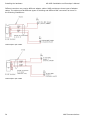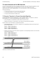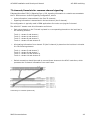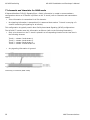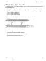
1
AG 4000 Installation and Developer's Manual
P/N 9000-60003-16
NMS Communications Corporation
100 Crossing Boulevard
Framingham, MA 01702
AG 4000 Installation and Developer's Manual
No part of this document may be reproduced or transmitted in any form or by any means without prior written consent of NMS
Communications Corporation.
© 2002 NMS Communications Corporation. All Rights Reserved.
Alliance Generation is a registered trademark of NMS Communications Corporation or its subsidiaries. NMS Communications, Natural
MicroSystems, AG, CG, CX, QX, Convergence Generation, Natural Access, CT Access, Natural Call Control, Natural Media, NaturalFax,
NaturalRecognition, NaturalText, Fusion, PacketMedia, Open Telecommunications, Natural Platforms, NMS HearSay, and HMIC are
trademarks or service marks of NMS Communications Corporation or its subsidiaries. Multi-Vendor Integration Protocol (MVIP) is a registered
trademark of GO-MVIP, Inc. UNIX is a registered trademark in the United States and other countries, licensed exclusively through X/Open
Company, Ltd. Windows NT, MS-DOS, MS Word, Windows 2000, and Windows are either registered trademarks or trademarks of Microsoft
Corporation in the United States and/or other countries. Clarent and Clarent ThroughPacket are trademarks of Clarent Corporation. Sun, Sun
Microsystems, the Sun logo are trademarks or registered trademarks of Sun Microsystems, Inc. in the United States and/or other countries. All
SPARC trademarks are used under license and are trademarks or registered trademarks of SPARC International, Inc. in the United States
and/or other countries. Products bearing SPARC trademarks are based upon an architecture developed by Sun Microsystems, Inc. All other
marks referenced herein are trademarks or service marks of the respective owner(s) of such marks. All other products used as components
within this product are the trademarks, service marks, registered trademarks, or registered service marks of their respective owners.
Every effort has been made to ensure the accuracy of this manual. However, due to the ongoing improvements and revisions to our products,
NMS Communications cannot guarantee the accuracy of the printed material after the date of publication or accept responsibility for errors or
omissions. Revised manuals and update sheets may be published when deemed necessary by NMS Communications.
P/N 9000-60003-16
Revision History
Revision
Release date
Notes
1.0
July, 2000
SRG
1.1
September, 2000
SRG
1.2
March, 2001
MVH
1.3
April, 2001
CYF
1.4
August, 2001
LBG
1.5
November, 2001
MVH
1.6
May, 2002
NBS, NACD 2002-1
Last modified: May 22, 2002
Refer to the NMS web site (www.nmscommunications.com) for product updates and for information about NMS support policies, warranty
information, and service offerings.
2
NMS Communications
Table of Contents
Introduction ..................................................................................................................... 7
Overview of the AG 4000 board ........................................................................................ 9
AG 4000 board features..................................................................................................... 9
Software components.......................................................................................................11
Natural Access..............................................................................................................11
NMS OAM ....................................................................................................................12
Configuration files .........................................................................................................13
Runtime software..........................................................................................................13
Trunk control programs (TCPs) .......................................................................................13
Installing the hardware .................................................................................................. 15
Installation summary .......................................................................................................15
AG driver software ........................................................................................................15
System requirements .......................................................................................................16
Configuring the hardware .................................................................................................17
Terminating the H.100 bus.............................................................................................17
Configuring the DIP switch .............................................................................................18
Installing the board..........................................................................................................19
Connecting to the T1 or E1 trunk .......................................................................................20
Connecting an AG 4000 T board to the network...................................................................21
Ordering T1 service.......................................................................................................22
Connecting an AG 4000 E board to the network...................................................................23
Connecting an AG 4000 E 120 Ohm.................................................................................23
Connecting an AG 4000 E 75 Ohm ..................................................................................23
Loopback configuration.....................................................................................................26
Configuring the board..................................................................................................... 27
Adding configurations to the NMS OAM database .................................................................27
Configuring the system using oamsys.................................................................................28
Creating a system configuration file for oamsys ................................................................28
Launching oamsys ........................................................................................................29
Changing configuration parameter settings .........................................................................30
Board keyword files.......................................................................................................30
Specifying configuration file location................................................................................31
Configuring board clocking................................................................................................32
AG 4000 Clocking Capabilities ........................................................................................32
Clock configuration methods ..........................................................................................34
Configuring AG 4000 board clocking using keywords .........................................................34
Example: Multiple board system .....................................................................................36
Echo cancellation .............................................................................................................38
Sample board keyword file................................................................................................39
AG 4000 board keyword file ...........................................................................................39
Verifying the installation ................................................................................................ 41
Verifying board installation ...............................................................................................41
Status indicator LEDs .......................................................................................................42
Verifying board operation .................................................................................................43
Demonstration programs ..................................................................................................44
AG 4000 switching.......................................................................................................... 45
AG 4000 switch model......................................................................................................45
H.100 streams..............................................................................................................45
Local streams ...............................................................................................................45
Switch model ...............................................................................................................46
Lucent T8100 switch blocking .........................................................................................47
NMS Communications
3
Table of Contents
AG 4000 Installation and Developer's Manual
T1 trunk channels and H.100 timeslots...............................................................................48
T1 Channels/Timeslots for Channel Associated Signaling....................................................48
T1 channels/timeslots for common channel signaling.........................................................49
T1 channels and timeslots for RAW mode.........................................................................50
E1 trunk channels and timeslots ........................................................................................51
E1 signaling for channel associated signaling....................................................................52
E1 signaling/timeslots for common channel signaling ........................................................52
E1 channels and timeslots for RAW mode.........................................................................53
Default connections for standalone board ...........................................................................54
Keyword reference ......................................................................................................... 57
Using Keywords...............................................................................................................57
Setting keyword values..................................................................................................57
Retrieving keyword values .............................................................................................58
Keyword summaries.........................................................................................................59
Editable keyword summary ............................................................................................59
Informational keyword summary ....................................................................................60
AG plug-in keyword summary.........................................................................................61
Using the keyword reference .............................................................................................62
AutoStart........................................................................................................................63
AutoStop ........................................................................................................................64
Boards[x] .......................................................................................................................65
BootDiagnosticLevel .........................................................................................................66
Buffers[x].Num ...............................................................................................................69
Buffers[x].Size ................................................................................................................70
Clocking.HBus.AutoFallBack ..............................................................................................71
Clocking.HBus.ClockMode .................................................................................................73
Clocking.HBus.ClockSource ...............................................................................................74
Clocking.HBus.ClockSourceNetwork ...................................................................................76
Clocking.HBus.FallBackClockSource....................................................................................77
Clocking.HBus.FallBackNetwork .........................................................................................78
Clocking.HBus.NetRefSource .............................................................................................79
Clocking.HBus.NetRefSourceNetwork .................................................................................80
Clocking.HBus.NetRefSpeed ..............................................................................................81
Clocking.HBus.Segment....................................................................................................82
DLMFiles[x].....................................................................................................................83
Driver.BoardID ................................................................................................................84
Driver.Name ...................................................................................................................85
DSP.C5x.DSPFiles[x] ........................................................................................................86
DSP.C5x.Image ...............................................................................................................88
DSP.C5x.Lib ....................................................................................................................89
DSP.C5x.Loader ..............................................................................................................90
DSP.C5x[x].Files[y] .........................................................................................................91
DSP.C5x[x].Image ...........................................................................................................92
DSP.C5x[x].Limits[y] .......................................................................................................93
DSP.C5x[x].Os ................................................................................................................95
DynamicRecordBuffers .....................................................................................................96
Eeprom.AssemblyRevision ................................................................................................98
Eeprom.BoardSpecific ......................................................................................................99
Eeprom.BusClkDiv ......................................................................................................... 100
Eeprom.CheckSum ........................................................................................................ 101
Eeprom.CPUSpeed ......................................................................................................... 102
Eeprom.DRAMSize ......................................................................................................... 103
Eeprom.DSPSpeed ......................................................................................................... 104
Eeprom.Family .............................................................................................................. 105
Eeprom.MFGWeek ......................................................................................................... 106
4
NMS Communications
AG 4000 Installation and Developer's Manual
Table of Contents
Eeprom.MFGYear ........................................................................................................... 107
Eeprom.MSBusType ....................................................................................................... 108
Eeprom.NumDSPCores ................................................................................................... 109
Eeprom.SerialNum......................................................................................................... 110
Eeprom.SoftwareCompatibility ........................................................................................ 111
Eeprom.SRAMSize ......................................................................................................... 112
Eeprom.SubType ........................................................................................................... 113
LoadFile........................................................................................................................ 114
LoadSize....................................................................................................................... 115
Location.PCI.Bus ........................................................................................................... 116
Location.PCI.Slot ........................................................................................................... 117
Location.Type................................................................................................................ 118
MaxChannels................................................................................................................. 119
Name ........................................................................................................................... 120
NetworkInterface.T1E1[x].ConfigFile ................................................................................ 121
NetworkInterface.T1E1[x].D_Channel .............................................................................. 122
NetworkInterface.T1E1[x].FrameType .............................................................................. 123
NetworkInterface.T1E1[x].ISDN.D_Channel_Backup_Trunk ................................................ 124
NetworkInterface.T1E1[x].ISDN.NFAS_Member.Count........................................................ 125
NetworkInterface.T1E1[x].ISDN.NFAS_Member[y].Board ................................................... 126
NetworkInterface.T1E1[x].ISDN.NFAS_Member[y].NAI ...................................................... 127
NetworkInterface.T1E1[x].ISDN.NFAS_Member[y].Trunk.................................................... 128
NetworkInterface.T1E1[x].ISDN.NFASGroup ..................................................................... 129
NetworkInterface.T1E1[x].Length .................................................................................... 130
NetworkInterface.T1E1[x].LineCode ................................................................................. 131
NetworkInterface.T1E1[x].SignalingType .......................................................................... 133
NetworkInterface.T1E1[x].Type ....................................................................................... 134
Number ........................................................................................................................ 135
Product ........................................................................................................................ 136
Products[x] ................................................................................................................... 137
RunFile......................................................................................................................... 138
SignalIdleCode .............................................................................................................. 139
State............................................................................................................................ 140
SwitchConnections......................................................................................................... 141
SwitchConnectMode ....................................................................................................... 142
SwitchDriver.Name ........................................................................................................ 143
TCPFiles[x] ................................................................................................................... 144
Version.Major................................................................................................................ 145
Version.Minor ................................................................................................................ 146
VoiceIdleCode ............................................................................................................... 147
Xlaw ............................................................................................................................ 148
Hardware specifications ............................................................................................... 149
General hardware specifications ...................................................................................... 149
General specifications.................................................................................................. 149
Protocols.................................................................................................................... 149
Host interface............................................................................................................. 149
H.100 compliant interface ............................................................................................ 150
Environment ................................................................................................................. 150
Power requirements ....................................................................................................... 150
Telephony interface ....................................................................................................... 151
CEPT E1 G.703 telephony interface ............................................................................... 151
DSX-1 telephony interface ........................................................................................... 151
Interoperability with MVIP-90.......................................................................................... 152
Connecting to the MVIP-90 bus ....................................................................................... 153
Compliance and regulatory certification ............................................................................ 154
NMS Communications
5
Table of Contents
AG 4000 Installation and Developer's Manual
T1 version.................................................................................................................. 154
E1 version.................................................................................................................. 154
EU R&TTE statement ................................................................................................... 154
Managing resources ..................................................................................................... 155
Functions for managing resources.................................................................................... 155
Default functions available for AG 4000 boards ............................................................... 155
Custom functions available for AG 4000 boards .............................................................. 156
DSP/task processor files and processing power.................................................................. 157
AG 4000 board processing .............................................................................................. 163
Customizing AG 4000 board functions .............................................................................. 164
Example 1: Configuring an AG 4000 board ..................................................................... 165
Data input and output queue constraints ....................................................................... 166
T1 and E1 trunk channels ............................................................................................. 167
Channels and transmission rates ..................................................................................... 167
Signaling ...................................................................................................................... 168
Channel Associated Signaling (CAS) .............................................................................. 168
Common Channel Signaling (CCS) ................................................................................ 168
Framing........................................................................................................................ 169
T1 framing ................................................................................................................. 169
E1 framing ................................................................................................................. 171
Voice encoding .............................................................................................................. 172
Companding............................................................................................................... 172
AMI, ones density, and zero code suppression ................................................................... 173
Migration ...................................................................................................................... 175
Migration overview......................................................................................................... 175
OAM service .................................................................................................................. 175
Configuration file changes............................................................................................... 175
Keyword changes .......................................................................................................... 176
6
NMS Communications
Introduction
The AG 4000 Installation and Developer's Manual explains how to configure and install an AG 4000
board, and how to verify that it has been installed correctly and is operating correctly. It also
provides some general information about developing an application that uses this telephony board.
This manual is targeted to developers of telephony and voice applications who are using the AG
4000 board with Natural Access. This manual defines telephony terms where applicable, but
assumes that readers are familiar with telephony concepts, switching, and the C programming
language.
NMS Communications
7
Overview of the AG 4000 board
AG 4000 board features
The AG 4000 board is part of the Alliance Generation family of telephony boards. It is available in
configurations with one to four T1 or E1 trunks. 400 to 4000 MIPS configuration are available for
voice processing. A variety of applications are supported. These include 120 ports of IVR and fax or
60 ports of NMS Fusion.
Refer to the NMS web site (www.nmscommunications.com) for a list of available AG 4000 board
configurations, for a list of countries where NMS has obtained approval for the AG 4000 board, and
for product updates.
An AG 4000 board contains the following main components:
•
DSP resources
Each board has 16 high-performance digital signal processors (DSPs) that provide resources
for 120 ports of call processing and programmable voice processing. Each DSP supports one or
more tasks. These tasks include voice recording and playback, DTMF detection and generation,
and call progress analysis. Fax and NMS Fusion are supported on an AG 4000 board.
The AG 4000/3200 T and E boards are shipped with a daughterboard that has an additional 16
or 24 high-performance digital signal processors (DSPs).
•
PCI bus connectivity
Each AG 4000 board is designed to reside in a single PCI bus slot. Each board contains a 5 volt
PCI bus interface compliant with the PCI specification, version 2.1. The PCI interface is a 33
Mhz, 32-bit target device.
•
Trunk connectivity
Each board contains T1 or E1 network interfaces for digital trunk connectivity.
•
H.100 bus connectivity
The AG 4000 board fully supports the H.100 bus specification. The H.100 bus allows boards to
share data and signaling information with other boards on the H.100 bus. For example, you
can connect two or more AG 4000 boards for applications that perform trunk-to-trunk
switching. You can add additional DSP resources, analog station interfaces, or loop start line
interfaces using other AG boards. You can also use MVIP compatible products from other
manufacturers with the AG 4000 board.
The H.100 interface supports the following stream configurations on the H.100 bus:
•
•
Full mode: 32 streams at 8 MHz each, which provides 128 timeslots each for a total of
4096 timeslots.
•
Backward compatibility mode: 16 8MHz streams, 16 2MHz streams (total of 2560
timeslots). The H.100 interface will operate with
MVIP-90 cards on the same bus. In these configurations, an H.100 board in the system
should be the bus master.
Telephony bus switching
Switching for the AG 4000 board is implemented with the HMIC (H.100/MVIP Integrated
Circuit). The HMIC is a single chip that offers full support for the H.100 bus within the MVIP
architecture providing access to all 4096 slots on the H.100 bus.
NMS Communications
9
Overview of the AG 4000 board
AG 4000 Installation and Developer's Manual
On the AG 4000 board, switch connections are allowed for up to 128 full duplex connections
between local devices and the H.100 bus. Non-blocking switch connections are allowed
between local devices.
The following illustration shows where these components are located on an AG 4000 board:
AG 4000 components
10
NMS Communications
AG 4000 Installation and Developer's Manual
Overview of the AG 4000 board
Software components
AG 4000 boards require the following software components:
•
The Natural Access development environment, which provides service APIs for call control,
system configuration, voice store and forward, and other functions.
•
NMS OAM (Operations, Administration, and Maintenance) software, which performs operations
on, administration of, and maintenance of telephony resources in a system. The OAM service
manages a database of configuration information for each telephony resource, including AG
boards.
•
Configuration files, which describe how each board is set up and initialized. These files are
used to initialize NMS OAM configuration parameters for the boards.
•
Runtime software, which controls the AG 4000 board.
•
One or more trunk control programs (TCPs). These programs allow your application to
communicate with the telephone network using the signaling schemes (protocols) used on the
trunk.
The following illustration shows how these software components relate to one another. Each
component is described in detail in the following sections.
Software components
Natural Access
Natural Access is a complete software development environment for voice applications. It provides
a standard set of functions grouped into logical services. Each service has a standard programming
interface. For more information about standard (base) and optional (domain) Natural Access
services, refer to the Natural Access Developer's Reference Manual.
NMS Communications
11
Overview of the AG 4000 board
AG 4000 Installation and Developer's Manual
NMS OAM
NMS OAM is a Natural Access component that administers and maintains resources in a system.
These resources include hardware components (including AG boards) and low-level board
management software modules (such as the Hot Swap process).
Using NMS OAM, you can:
•
Create, delete, and query the configuration of a component
•
Start (boot), stop (shut down), and test a component
•
Receive notifications from components
NMS OAM maintains a database containing records of configuration information for each
component. This information consists of parameters and values. Refer to the following illustration:
NMS OAM components
Each parameter and value is expressed as a keyword name/value pair (for example, AutoStart =
NO). You can use NMS OAM to maintain and update configuration parameters for any component.
Keywords and values can be added, modified, or deleted.
To use NMS OAM, ensure ctdaemon is running. For more information about ctdaemon, refer to the
Natural Access Developer's Reference Manual. For more information about NMS OAM, refer to the
NMS OAM System User's Manual.
AG board plug-in
NMS OAM uses the AG board plug-in software module to communicate with AG boards. The AG
plug-in, agplugin.bpi, is included with the NMS OAM software. It is installed in the nms\bin
directory by default (/opt/nms/lib under UNIX). The file must reside in this directory in order for
NMS OAM to load it when it starts up.
12
NMS Communications
AG 4000 Installation and Developer's Manual
Overview of the AG 4000 board
Configuration files
When you set up your system, you create a record in the NMS OAM database for each board that
contains configuration information for the board. To do so, supply the information in the
configuration file and run the oamsys utility. This utility creates the records and then directs NMS
OAM to start the boards according to the specified configuration information.
Sample board keyword files are shipped with the software. Refer to Configuring the system using
oamsys for more information about the system configuration files and oamsys.
Runtime software
The runtime software consists of runfiles and DSP files. The runfile is the basic low-level software
that an AG board requires to operate. DSP files enable the AG board's on-board digital signal
processors to perform certain tasks, such as DTMF signaling, voice recording, and playback.
Several runfiles and DSP program files are installed with Natural Access. Specify the files to use for
your configuration in the board keyword file. When NMS OAM boots a board, the runfiles and DSP
files are transferred from the host into on-board memory.
For more information about board keyword files, refer to Configuring the system using oamsys of
this manual. For more information about the DSP files shipped with Natural Access, refer to the ADI
Service Developer's Reference Manual.
Trunk control programs (TCPs)
AG 4000 boards are compatible with a variety of signaling schemes, called protocols. A Trunk
Control Program (TCP) performs all of the signaling tasks to interface with the protocol used on a
channel.
Several different protocol standards are used throughout the world. These standards differ
considerably from country to country. For these reasons, different TCPs are supplied with Natural
Access for various protocols and country-specific variations.
You can load more than one TCP at a time for applications that support multiple protocols
simultaneously. TCPs are specified in the configuration file and are downloaded to the board by
oamsys. TCPs run on the board, relieving the host computer from the task of processing the
protocol directly. For more information about TCPs, refer to the NMS CAS for Natural Call Control
Developer's Manual.
NMS Communications
13
Installing the hardware
Installation summary
The following table summarizes the procedure for installing the hardware and software
components:
Step
Description
For details, refer to...
1
Ensure that your PC system meets the system
requirements.
System requirements of this manual.
2
Install the AG 4000 board into one of the computer's
PCI bus slots.
Installing the hardware of this manual.
3
If you have any MVIP-90 boards, connect the MVIP Bus
Adapter to one AG 4000 board and the MVIP-90 bus
connector to the MVIP Bus Adapter.
Hardware specifications of this manual.
4
If there are multiple H.100 boards, connect the H.100
bus to your H.100 boards.
Installing the hardware of this manual.
5
Install Natural Access, which also installs the
AG 4000 board driver and runtime software.
AG driver software of this manual.
6
Add configuration information for each board to the NMS
OAM database.
Configuring the system using oamsys of this manual and
the NMS OAM System User's Manual.
7
Direct the OAM service to start the boards.
Configuring the system using oamsys of this manual and
the NMS OAM System User's Manual.
8
Verify that the installation is operational.
Verifying the installation of this manual.
Note: If your system is powered down, you may want to install the board before you install the
software. It does not matter if you install the board or the software first.
The BootDiagnosticLevel keyword in the board's keyword file determines the type of board
diagnostic tests that take place when you boot the board. If a test fails, the test number is
reported back as an error code. You must be running oammon to view diagnostic results.
For more information about valid settings for the keyword, refer to BootDiagnosticLevel in the
keyword reference section. For more information about board level error messages, refer to the
NMS Board and Driver Errors Manual.
AG driver software
The following drivers are installed with Natural Access for AG 4000 boards:
Operating system
Driver names
Windows 2000
aghwwin2k
agwin2k
Red Hat Linux
aghw.o
UNIX
aghw
agsw
ag95sw
agmx
NMS Communications
15
Installing the hardware
AG 4000 Installation and Developer's Manual
System requirements
To install and use AG 4000 boards, your system must have:
•
An available PCI bus slot
•
Natural Access version 4.0 or later (including the ADI service) installed
•
An H.100 bus connector cable if you are connecting to other H.100 boards
•
An MVIP-90 connector cable if you are connecting to MVIP-90 boards
•
An MVIP Bus Adapter if you are connecting to the MVIP-90 bus
•
Cables to connect to a T1 trunk or to an E1 trunk
•
A grounded chassis (with three-prong power cord)
An uninterruptable power supply (UPS) is recommended for increased system reliability. The UPS
does not need to power the PC's video monitor except in areas prone to severe lightning storms.
16
NMS Communications
AG 4000 Installation and Developer's Manual
Installing the hardware
Configuring the hardware
Caution:
The AG 4000 board is shipped in a protective anti-static container. Leave the board in its container until you
are ready to install it. Handle the board carefully and only hold it by its edges. We recommend that you wear
an anti-static wrist strap connected to a good earth ground whenever you handle the board. Take care not to
touch the gold fingers which plug into the PCI bus connectors.
This topic discusses:
•
Terminating the H.100 bus
•
Configuring the DIP switch
Terminating the H.100 bus
In your system, the H.100 boards are connected to one another with an H.100 bus cable. The two
boards located at the end of the H.100 bus must have bus termination enabled, as shown in the
following illustration. Bus termination is controlled by a DIP switch as explained in Configuring the
DIP switch.
H.100 bus configuration
If your system contains MVIP-90 boards, one of your AG 4000 boards will be connected to the
H.100 bus and to the MVIP-90 bus using the MVIP Bus Adapter. The two ends of the H.100 bus
must be terminated. The two ends of the MVIP-90 bus must not be terminated. The AG 4000 board
does not terminate the MVIP-90 bus.
NMS Communications
17
Installing the hardware
AG 4000 Installation and Developer's Manual
Configuring the DIP switch
The AG 4000 DIP switches are located on the back of the board.
DIP switch S1 (shown in the following illustration) controls the H.100 bus termination. By default,
all S1 switches are set to OFF (H.100 bus termination disabled). Setting the S1 switches to ON
enables H.100 bus termination. You should only set all S1 switches to ON for the boards that are
on the ends of the H.100 bus.
Note: The switches in the DIP switch S1 should be set to either all ON or all OFF.
DIP switches on the AG 4000 board
Switches S2 - S5 are factory-configured and should not be changed.
18
NMS Communications
AG 4000 Installation and Developer's Manual
Installing the hardware
Installing the board
Once you have configured the DIP switch on the board, you are ready to install the board in your
system and connect the board to the trunk.
To install an AG 4000 board in your system:
1. If necessary, configure the board as described in Configuring the hardware.
2. Turn off the computer and disconnect it from the AC power source. Remove the cover and set
it aside.
3. If you are placing the board into:
•
A PCI chassis, remove the PCI retainer bracket by unscrewing it from the board. The
bracket is not needed for the board to properly fit into the chassis. The PCI retainer
bracket is show in the following illustration.
•
An ISA chassis, leave the PCI retainer bracket attached to the board. The bracket is
needed for the board to properly fit into the chassis.
PCI retainer bracket
4. Arrange your AG 4000 board and other H.100 boards in adjacent PCI bus slots.
Make sure each board's PCI bus connector is seated securely in a slot.
5. If your system contains MVIP-90 boards:
a. Arrange the MVIP-90 boards in adjacent ISA bus slots. Make sure each board's ISA bus
connector is seated securely in a slot.
b. Connect the MVIP-90 boards to the MVIP-90 bus cable.
c. Connect the MVIP Bus Adapter to the AG 4000 board and to the
MVIP-90 bus cable as described in Hardware specifications.
d. Connect the AG 4000 board to the H.100 bus cable.
6. If you have multiple H.100 boards, connect the H.100 bus cable to each of the H.100 boards.
7. Replace the cover, and connect the computer to its AC power source.
NMS Communications
19
Installing the hardware
AG 4000 Installation and Developer's Manual
Connecting to the T1 or E1 trunk
WARNING:
Important safety notes for telephony connections
•
Installation of this board and associated telephone wiring is to be performed only by
competent technical personnel.
•
Make sure the PC chassis is grounded through the AC power cord or by other means before
connecting the telephone line.
•
If your system requires an external power supply, make sure it is grounded through the AC
power cord or by other means.
•
Never install telephone wiring during a lightning storm.
•
Never install telephone jacks in wet locations.
Telephone companies provide primary lightning protection for their telephone lines. However, if a
site connects to private lines that leave the building, make sure that external protection is
provided.
As shown in the following illustration, AG 4000 boards come with up to four RJ-48C connectors.
Shielded cables are also available with AG 4000 boards.
AG 4000 end bracket with four RJ-48C connectors
Each of the RJ-48C connectors has the pinouts shown in the following illustration:
RJ-48C pinouts
20
NMS Communications
AG 4000 Installation and Developer's Manual
Installing the hardware
Connecting an AG 4000 T board to the network
Caution:
You must complete all required performance tests, and a type approval certificate must be granted by the
appropriate regulatory authority in the target country before you can connect the AG Quad T board to the
public network.
The AG 4000 T boards have up to four DSX-1 trunk interfaces.
WARNING:
Important Safety Notes for Telephony Connections
The cables attached to this product must be isolated by a Channel Service Unit (CSU) before the
cables leave the building.
For typical T1 communications, each trunk interface connects to a Channel Service Unit (CSU), that
is connected to a T1 trunk line. The CSU provides a DSX-1 interface to the T1 line, and also
contains circuitry that allows the Central Office (CO) to perform diagnostic tests remotely.
AG 4000 T trunk interface with CSU
You can purchase or lease the CSU from the telephone company or other vendor. The CSU must be
compatible with DSX-1 specifications, particularly in maintaining the pulse amplitude level between
2.3 and 4.2 volts.
You can also connect the board directly to the T1 line, without a CSU. This setup is most common
in applications where the T1 line is proprietary, and is not connected directly to the public network.
AG 4000 T trunk interface (no CSU)
To avoid causing alarms at your T1 service provider's end, make sure that there is always a valid
signal being sent, either by looping back at the CSU, or by connecting the CSU to a functioning AG
4000 T board. The best way to provide a loopback is to unplug your cable from the CSU. The
modular connector on most CSUs will loop back transmit to receive when nothing is plugged in.
NMS Communications
21
Installing the hardware
AG 4000 Installation and Developer's Manual
Ordering T1 service
When you order T1 service, the telephone company needs information about your system. For
example, to order basic T1 service for the AG 4000/1600-4T board or the AG 4000/3200-4T board
in the United States, specify this information:
Product manufacturer:
NMS Communications
Product name:
AG 4000/1600-4T board, AG 4000/3200-4T board, or
AG 4000/4000-4T board
Service type:
T1 (D4 or ESF frame formats) (B8ZS or AMI line codes are also supported)
Start:
Wink start
Dial tone:
Enabled (standard frequency)
Digits:
DTMF (pulse dial supported, but DTMF preferred)
Interface code:
04DU9-B
Service code:
6.0P
Channels:
96
Ringer equivalence:
0.0A
Outdial senderized:
Yes
FCC registration:
Located on label on board
USOC jack required:
RJ-48C
22
NMS Communications
AG 4000 Installation and Developer's Manual
Installing the hardware
Connecting an AG 4000 E board to the network
Caution:
NMS obtains board-level approvals certificates for supported countries. Some countries require that you obtain
system-level approvals before connecting to the public network. To learn what approvals you require, contact
the appropriate regulatory authority in the target country.
The AG 4000 E board can provide up to four CEPT E1 interfaces. For typical E1 communications,
each E1 interface connects directly to an E1 trunk, as shown in the following illustration:
AG 4000 E trunk interface
Connecting an AG 4000 E 120 Ohm
NMS provides shielded RJ-48 cables (NMS P/N 31082) and connection boxes (NMS P/N 2282) for
connecting AG 4000 E 120 Ohm boards to E1 trunks. Failing to use a shielded cable can negate
your Class B approval.
Connecting an AG 4000 E 75 Ohm
To connect an AG 4000 E 75 Ohm board to the E1 trunk, use an RJ-48 to BNC adapter cable:
RJ-48 to BNC adapter cable
NMS Communications
23
Installing the hardware
AG 4000 Installation and Developer's Manual
Different countries may require different adapter cables. NMS provides are three types of adapter
cables. The cables provide different types of shielding and different BNC connectors as shown in
the following illustrations:
Cable adapter P/N 31065
Cable adapter P/N 31066
24
NMS Communications
AG 4000 Installation and Developer's Manual
Installing the hardware
Cable adapter P/N 31067 is the most commonly used cable. The shield for this cable is connected
to both transmit and receive BNC connectors:
Cable adapter P/N 31067
The following table describes each of the adapter cables:
Cable
Description
P/N 31065
Shield is not connected to transmit and receive connectors.
P/N 31066
Shield is connected to transmit connector outer conductor.
P/N 31067
Shield is connected to transmit and receive outer conductors.
NMS Communications
25
Installing the hardware
AG 4000 Installation and Developer's Manual
Loopback configuration
You can connect the AG 4000 board in loopback mode to test your digital trunk application without
actually connecting to the telephone network. the following illustration shows the loopback
configuration connecting trunk 1 and trunk 2 with cross-over cable P/N 31071 on an AG 4000
board:
Loopback configuration
The cross-over cable connects transmit from one trunk to receive on another trunk by connecting
the pins as shown in the illustration.
26
NMS Communications
Configuring the board
Adding configurations to the NMS OAM database
Each board that NMS OAM configures and starts must have a separate set of configuration
parameters. Each parameter value is expressed as a keyword name/value pair (for example,
AutoStart = NO). You can use NMS OAM to retrieve parameters for any component. These
parameters (set through board keywords) can be added, modified, or deleted.
Before using NMS OAM, make sure that the Natural Access Server (ctdaemon) is running. For more
information about Natural Access Server, refer to the Natural Access Developer's Reference
Manual.
The following utilities are shipped with NMS OAM:
Utility
Description
oamsys
Configures and starts up boards on a system-wide basis. Attempts to start all specified boards based on system
configuration files you supply.
oamcfg
Provides greater access to individual OAM service configuration functions. For more information about this utility,
refer to the NMS OAM System User's Manual.
Note: Applications can control NMS OAM using OAM service functions. For more information, refer
to the NMS OAM Service Developer's Reference Manual.
NMS Communications
27
Configuring the board
AG 4000 Installation and Developer's Manual
Configuring the system using oamsys
To configure a system using the oamsys utility:
1. Install the boards and software as described in Installing the board.
2. Determine the PCI bus and slot locations of the boards, using the pciscan utility. The pciscan
utility identifies the NMS PCI boards installed in the system, and returns each board's bus,
slot, interrupt, and board type.
3. Create a system configuration file describing the board configuration. In this file, give each
board a unique name and board number. A sample configuration file is provided.
4. Use oamsys to set up records in the NMS OAM database based on this file and to start all
installed boards.
Note: If you want to determine the location of a specific board, use pciscan to associate the PCI
bus assignment to a physical board by flashing an LED on the board. To flash the LED on a
board, call pciscan with the PCI bus and PCI slot locations.
For more information about pciscan, refer to the NMS OAM System User's Manual.
Creating a system configuration file for oamsys
Create a system configuration file describing all of the boards in your system. oamsys creates the
records, and then directs NMS OAM to start the boards, configured as specified.
The system configuration file is typically named oamsys.cfg. By default, oamsys looks for a file with
this name when it starts up.
Refer to the NMS OAM System User's Manual for specific information on the syntax and structure of
this file.
The following chart describes the AG board-specific settings to include in the system configuration
file for each AG board:
Keyword
Description
Allowed values for AG boards
[name]
Name of the board to be used to refer to the board in
the software. The board name must be unique.
Any string, in square brackets [].
Product
Name of the board product.
AG_4000_1T1
AG_4000_1E1
AG_4000_2T1
AG_4000_2E1
AG_4000_4T1
AG_4000_4E1
Number
Board number you will use in your Natural Access
application to refer to the board.
Each board's number must be unique.
Bus
PCI bus number. The bus:slot location for each board
must be unique.
Values returned by pciscan.
Slot
PCI slot number. The bus:slot location for each board
must be unique.
Values returned by pciscan.
28
NMS Communications
AG 4000 Installation and Developer's Manual
Configuring the board
Keyword
Description
Allowed values for AG boards
File
Name of the board keyword file containing settings
for the board.
You can create your own custom board keyword file if
you wish. For details, refer to Changing configuration
parameter settings.
Several board keyword files are installed with the AG
software, one for each country or region.
You can specify more than one file after the File
keyword:
File=mya.cfg myb.cfg myc.cfg
Alternatively, you can specify the File keyword more
than once:
File = mya.cfg
File = myb.cfg
File = myc.cfg
Board keyword files are sent in the order listed. The
value for a given keyword in each file overrides any
value specified for the keyword in earlier files.
Sample system configuration file
The following system configuration file describes two AG 4000 T1 boards, both to be configured for
the United States:
[First AG
Product =
Number =
Bus
=
Slot
=
File
=
[Second
Product
Number
Bus
Slot
File
4000]
AG_4000_4T1
0
0
15
agpi4000.cfg
AG 4000]
= AG_4000_4T1
= 1
= 0
= 16
= agpi4000.cfg
Launching oamsys
To launch oamsys, enter oamsys on the command line.
If you invoke oamsys without command line options, it searches for a file named oamsys.cfg in the
paths specified in the AGLOAD environment variable.
When invoked with a valid filename, oamsys:
•
Checks the syntax of the system configuration file and verifies that all required keywords are
present.
Note: oamsys checks the syntax only on the system configuration file, and not on any board
keyword files referenced in the system configuration file. oamsys reports all syntax errors it
finds.
•
Checks for uniqueness of board name, number and bus/slot.
•
Attempts to start all boards as described in the system configuration file and board keyword
files.
Note: The Natural Access Server (ctdaemon) must be running for oamsys to operate. For more
information about the Natural Access Server, refer to the Natural Access Developer's
Reference Manual.
NMS Communications
29
Configuring the board
AG 4000 Installation and Developer's Manual
Changing configuration parameter settings
When you run oamsys, the utility starts all boards according to the configuration parameters
specified in their associated board keyword files.
Specify parameters in board keyword files as name/value pairs: AutoStart = NO. To change a
parameter:
•
Use or modify one of the sample board keyword files corresponding to your country and board
type. Specify the name of this new file in the File statement in oamsys.cfg and run oamsys
again. Refer to the NMS OAM System User's Manual for information about the syntax of NMS
OAM board keyword files.
•
Specify parameter settings using the oamcfg utility. Refer to the NMS OAM System User's
Manual for more information about oamcfg.
•
Create a new board keyword file, either with additional keywords, or keywords whose values
override earlier settings.
•
Specify the settings using OAM service functions. Refer to the NMS OAM Service Developer's
Reference Manual for more information about OAM service functions.
You can use oamsys to:
•
Change which software module files are downloaded to the board at startup. Refer to
Specifying configuration file location for more information.
•
Specify board switching (AG 4000 switch model).
•
Configure CT bus clocking (Configuring board clocking).
Board keyword files
A sample set of board keyword files are installed by the AG installation. These board keyword files
are for the U.S. digital protocols:
File
Description
agpi4000.cfg
AG 4000 T
a4fgdpi.cfg
AG 4000 T, Feature Group D protocol
a4gdspi.cfg
AG 4000 T, Digital Ground Start protocol
a4opspi.cfg
AG 4000 T, Off-Premises Station protocol
a4ss5pi.cfg
AG 4000 T, Signaling System 5 protocol
a4wnkpi.cfg
AG 4000 T, Two-way Wink Start protocol
agi4t1pi.cfg
AG 4000 T, ISDN
agi4e1pi.cfg
AG 4000 E, ISDN
Sample board keyword files are shown in Sample board keyword file. These board keyword files
have many keywords in common. The differences in these files are related to the protocols, whose
names appear as part of the name of the file. For more information about board keyword files,
refer to the NMS OAM System User's Manual.
30
NMS Communications
AG 4000 Installation and Developer's Manual
Configuring the board
Specifying configuration file location
Files to be downloaded on the AG boards are specified with keywords in the AG board's keyword
file. For example:
DLMFiles[0] = filename
If filename contains a path specification, the OAM service searches for the file in the specified
directory. Otherwise, it searches for the file in the current working directory of ctdaemon. If the file
does not exist in the current working directory, NMS OAM searches for the file in the search path
defined by the AGLOAD environment variable.
NMS Communications
31
Configuring the board
AG 4000 Installation and Developer's Manual
Configuring board clocking
When multiple boards are connected to the CT bus, you must set up a bus clock to synchronize
timing between them. In addition, you can configure alternative (or fallback) clock sources to
provide the clock signal if the primary source fails.
This topic describes:
•
AG 4000 board clocking capabilities
•
Clock configuration methods
•
Configuring clocking using keywords
To create a robust clocking configuration, you must understand basic clocking concepts such as
clock mastering and clock fallback. This section assumes that you have a basic understanding of CT
bus clocking. For a complete overview of CT bus clocking, refer to the NMS OAM System User's
Manual.
AG 4000 Clocking Capabilities
This section describes the rules and limitations that apply to setting up CT bus clocking for AG 4000
boards.
When an AG 4000 board is configured as the system primary clock master:
•
The board's first timing reference must be set to a network trunk, NETREF1, or OSC. NMS
recommends that you use a network trunk or OSC.
•
The board's fallback timing reference must be set to a network trunk.
When an AG 4000 board is configured as the system secondary clock master:
•
The board's first timing reference must be the system's primary clock.
•
The board's fallback timing reference must be set to a network trunk, NETREF1, OSC.
When an AG 4000 board is configured as a clock slave:
•
The board's first timing reference must be the system's primary clock.
•
The board's fallback timing reference must be the system's secondary clock.
•
If there is no secondary clock master for the system, the board's fallback timing reference
must be set to OSC. In this case, if clock fallback occurs, the board is not synchronized with
the system until you reconfigure the board's clocking.
The following tables summarize the AG board CT bus clocking capabilities for AG 4000 boards:
Clocking capabilities as primary master
Capability
Yes/No
Serve as primary master
Yes
Drive A_CLOCK
Yes
Drive B_CLOCK
Yes
Comments
Available primary timing references:
Local trunk
Yes
The secondary timing reference must also be a local trunk.
NETREF1
Yes
The application must reconfigure the board as soon as
possible if NETREF1 fails.
NETREF2
No
NETREF2 is available for H.110 boards only.
OSC
Yes
32
NMS Communications
AG 4000 Installation and Developer's Manual
Capability
Yes/No
Fallback to secondary timing reference
Yes
Configuring the board
Comments
Available secondary timing references:
Local trunk
Yes
NETREF1
No
NETREF2
No
OSC
No
Slave to secondary master if both references
fail
Yes
This is the only valid reference if the primary timing
reference is a local trunk.
NETREF2 is available for H.110 boards only.
Clocking capabilities as secondary master
Capability
Yes/No
Serve as secondary master
Yes
Comments
Drive A_CLOCK
Yes
If the primary master drives B_CLOCK, the secondary master drives
A_CLOCK.
Drive B_CLOCK
Yes
If the primary master drives A_CLOCK, the secondary master drives
B_CLOCK.
Available secondary timing references:
Local trunk
Yes
NETREF1
Yes
NETREF2
No
OSC
Yes
NETREF2 is available for H.110 boards only.
Clocking capabilities as slave
Capability
Yes/No
Serve as slave
Yes
Slave to A_CLOCK
Yes
Slave to B_CLOCK
Yes
Comments
Available fallback timing references:
A_CLOCK
Yes
B_CLOCK
Yes
OSC
Yes
The board is not synchronized until the application reconfigures the
clock.
Other clocking capabilities
Capability
Yes/No
Drive NETREF1
Yes
Drive NETREF2
No
Operate in standalone mode
Yes
NMS Communications
Comments
NETREF2 is available for H.110 boards only.
33
Configuring the board
AG 4000 Installation and Developer's Manual
Clock configuration methods
You can configure clocking in your system in one of two ways:
Method
Description
Using clockdemo application
model
Create an application that assigns each board a clocking mode, monitors clocking
changes, and reconfigures clocking when clock fallback occurs.
A sample clocking application, clockdemo, is provided with Natural Access. clockdemo
provides a robust fallback scheme that suits most system configurations. clockdemo
source code is included, allowing you to modify the program if your clocking configuration
is complex. For more information about clockdemo, refer to the NMS OAM System User's
Manual.
Note: Most clocking applications (including clockdemo) require that all boards on the CT
bus be started in standalone mode. To learn how to set AG 4000 boards to start in
standalone mode, refer to Standalone mode.
Using board keywords (with or
without application
intervention)
For each board on the CT bus, set each board's keywords to determine the board's
clocking mode and determine how it behaves if clock fallback occurs.
This method is described in the sections that follow. Unlike the clockdemo application,
which allows several boards to take over mastery of the clock when another board fails,
the board keyword method only specifies a single secondary clock master. For this
reason, the board keyword method is best used to implement clock fallback in test
configurations where clock reliability is not a factor.
The board keyword method does not create an autonomous clock timing environment. An
application must intervene to reset clocking after clock fallback occurs before other
clocking changes occur. If both the primary and secondary clock masters stop driving the
CT bus clock, and an application does not intervene, the boards default to standalone
mode.
Choose only one of these configuration methods across all boards on the CT bus. Otherwise, the
two methods can interfere with one another, and board clocking may not operate properly.
Configuring AG 4000 board clocking using keywords
AG 4000 board keywords allow you to configure the board in the following ways:
•
System primary clock master
•
System secondary clock master
•
Clock slave
•
Standalone mode
You can also use board keywords to establish clock fallback sources.
The following sections describe how to use board keywords to specify the clocking role of each AG
4000 board in a system.
34
NMS Communications
AG 4000 Installation and Developer's Manual
Configuring the board
Primary clock master
Use the following board keywords to configure an AG 4000 board as a primary clock master:
Keyword
Description
Clocking.HBus.ClockSource
Specifies the source from which this board derives its timing. Set this keyword to a
network source (NETREF or NETWORK).
Clocking.HBus.ClockSourceNetwork
Specifies the trunk number that the board uses as an external network clocking
source for its internal clock. Trunk numbering is 1-based.
Clocking.HBus.ClockMode
Specifies the CT bus clock that the board drives. Set this keyword to reference either
the A clock (MASTER_A) or to the B_CLOCK (MASTER_B).
Clocking.HBus.AutoFallBack
Enables or disables clock fallback on the board.
Clocking.HBus.FallBackClockSource
Specifies an alternate timing reference to use when the master clock source fails.
Set this keyword to a network timing source (NETWORK).
Clocking.HBus.FallBackNetwork
Specifies the trunk from which a fallback network timing source (for the clock
fallback reference) can be derived.
Note: If the primary master's first source fails and then returns, the board's timing reference (and
consequently, the reference for any slaves) switches back to the first timing reference. This
is not true for the secondary timing master.
Secondary clock master
Use the following board keywords to configure an AG 4000 board as a secondary clock master:
Keyword
Description
Clocking.HBus.ClockSource
Specifies the source from which this board derives its timing. Set this keyword to the
clock driven by the primary clock master. For example, if the primary master drives
the A_CLOCK, set this keyword to A_CLOCK.
Clocking.HBus.ClockMode
Specifies the CT bus clock that the secondary master drives. Set this keyword to
reference the clock (MASTER_A or MASTER_B) not driven by the primary clock
master.
Clocking.HBus.AutoFallBack
Enables or disables clock fallback on the board. Set this keyword to YES.
Clocking.HBus.FallBackClockSource
Specifies the alternate timing reference to use when the master clock does not
function properly. Set this keyword to reference a network source (NETREF or
NETWORK).
Clocking.HBus.FallBackNetwork
Specifies the trunk from which a fallback network timing source (for the clock
fallback reference) can be derived.
Note: If the primary master's timing reference recovers, the secondary master continues to drive
the clock referenced by all clock slaves until the application intervenes.
Clock slave
Use the following board keywords to configure an AG 4000 board as a clock slave:
Keyword
Description
Clocking.HBus.ClockMode
The CT bus clock from which the board derives its timing. Set this keyword to SLAVE
to indicate that the board does not drive any CT bus clock (although the board can
still drive NETREF).
Clocking.HBus.ClockSource
Specifies the source from which this clock derives its timing. Set this keyword to the
clock driven by the primary clock master.
Clocking.HBus.AutoFallBack
Enables or disables clock fallback on the board.
Clocking.HBus.FallBackClockSource
Specifies the alternate clock reference to use when the master clock does not
function properly. Set this keyword to the clock driven by the secondary clock
master (A_CLOCK or B_CLOCK).
NMS Communications
35
Configuring the board
AG 4000 Installation and Developer's Manual
Standalone mode
To configure an AG 4000 board in standalone mode so the board references its own clocking
information, set Clocking.HBus.ClockMode to STANDALONE. The board can use either its own
oscillator or a signal received from a digital trunk as a timing signal reference. However, the board
cannot make switch connections to the CT bus.
Example: Multiple board system
The following example assumes a system configuration in which three AG 4000 boards reside in a
single chassis. You can use board keywords to configure the boards in the following way:
Board
Configuration
Board 0
System primary bus master (driving the A clocks)
Board 1
System secondary bus master (driving the B clocks)
Board 2
Clock slave (clock fallback enabled)
This configuration assigns the following clocking priorities:
Priority
First
Timing reference
Board 0, digital trunk 1.
A network signal from a digital trunk provides the primary master clock source.
Second
Board 0, digital trunk 3.
A network signal from a digital trunk provides the clock fallback source.
Third
Board 1, digital trunk 2.
A network signal from a digital trunk provides the secondary master clock fallback source.
The following illustration shows a multi-board system with a primary and secondary clock master:
Sample board clocking configuration
36
NMS Communications
AG 4000 Installation and Developer's Manual
Configuring the board
The following table shows board keywords used to configure the boards according to the
configuration shown in the Sample board clocking configuration illustration:
Board
Role
Clocking keyword settings
0
Primary clock master
Clocking.HBus.ClockMode = MASTER_A
Clocking.HBus.ClockSource = NETWORK
Clocking.HBus.ClockSourceNetwork = 1
Clocking.HBus.AutoFallBack = YES
Clocking.HBus.FallBackClockSource = NETWORK
Clocking.HBus.FallBackNetwork = 3
1
Secondary clock master
Clocking.HBus.ClockMode = MASTER_B
Clocking.HBus.ClockSource = A_CLOCK
Clocking.HBus.AutoFallBack = YES
Clocking.HBus.FallBackClockSource = NETWORK
Clocking.HBus.FallBackNetwork = 2
2
Clock slave
Clocking.HBus.ClockMode = SLAVE
Clocking.HBus.ClockSource = A_CLOCK
Clocking.HBus.AutoFallBack = YES
Clocking.HBus.FallBackClockSource = B_CLOCK
In this configuration, Board 0 is the primary clock master and drives A_CLOCK. All slave boards on
the system use A_CLOCK as their first timing reference. Board 0 references its timing from a
network timing signal received on its own trunk 1. Board 0 also uses its own trunk 3 as its clock
fallback source. If the network timing signal derived from trunk 1 fails, Board 0 continues to drive
A_CLOCK based on trunk 3.
If, however, both of the clocking signals used by Board 0 fail (trunks 1 and 3), then Board 0 stops
driving A_CLOCK. The secondary clock master (Board 1) then falls back to a timing reference
received on its own trunk 2, and uses this signal to drive B_CLOCK. B_CLOCK then becomes the
timing source for all boards that use B_CLOCK as their backup timing reference.
Note: For this fallback scheme to work, all clock slaves must specify the A_CLOCK as the clock
source and B_CLOCK as the clock fallback source.
NMS Communications
37
Configuring the board
AG 4000 Installation and Developer's Manual
Echo cancellation
Echo cancellation is generally not required on digital trunks. It is disabled, by default, on AG 4000
boards. Because echo cancellation consumes many MIPS of DSP processing power, it may require a
version of the AG 4000 board with more than 16 DSPs. Refer to Resource usage for specific
configuration requirements.
Refer to the ADI Service Developer's Reference Manual for more information about configuring
echo cancellation on the AG 4000 board.
38
NMS Communications
AG 4000 Installation and Developer's Manual
Configuring the board
Sample board keyword file
This section shows the sample board keyword file agpi4000.cfg (other sample board keyword files
are located in the ag\cfg subdirectory under the Natural Access installation directory). agpi4000.cfg
uses NMS OAM board keywords to configure and start an AG 4000 T board. Follow the instructions
in the file to configure an AG 4000 E board.
AG 4000 board keyword file
This is the agpi4000.cfg file:
#
#
#
AG configuration file for AG 4000
Clocking.HBus.ClockSource = OSC
Clocking.HBus.ClockMode = STANDALONE
# TCP files are shipped with the NMS CAS sub-package of Natural Access.
# Be sure that you installed the protocols that are specified below before
# trying to start a board with this configuration file.
TCPFiles[0] = nocc.tcp
# "no trunk control" protocol
TCPFiles[1] = wnk0.tcp
# 2-way wink protocol
# DSP (.m54) files to link in
DSP.C5x.DSPFiles = callp.m54 dtmf.m54 mf.m54 ptf.m54 tone.m54 voice.m54
DLMFiles[0] = gtp.leo
DLMFiles[1] = voice.leo
DLMFiles[2] = svc.leo
#-------------------------------------------------------------------------# IF YOU ARE CONFIGURING AN E1 BOARD replace AMI_ZCS with HDB3 and D4 with
# CEPT to successfully boot the board. Consult AG 4000 documentation to
# determine proper configuration for your needs.
#-------------------------------------------------------------------------# For AG 4000 Quad (comment other "NetworkInterface" lines if used)
NetworkInterface.T1E1[0..3].LineCode = AMI_ZCS
NetworkInterface.T1E1[0..3].FrameType = D4
# For AG 4000 Dual (comment other "NetworkInterface" lines if used)
#
# NetworkInterface.T1E1[0..1].LineCode = AMI_ZCS
# NetworkInterface.T1E1[0..1].FrameType = D4
# For AG 4000 Single (comment other "NetworkInterface" lines if used)
#
# NetworkInterface.T1E1[0].LineCode = AMI_ZCS
# NetworkInterface.T1E1[0].FrameType = D4
NMS Communications
39
Verifying the installation
Verifying board installation
This section provides procedures to verify that the AG 4000 board is installed and configured
correctly. Before you begin, make sure you have created a system configuration file and a board
keyword file. For more information about these files, refer to Configuring the system using oamsys.
To verify that you have installed the board correctly:
1. Create a board keyword file to boot an AG 4000 board by copying or editing one of the sample
board keyword files to match your specific configuration. Refer to Configuring the system
using oamsys for more information about the board keyword files. You may want to use the
a4wnkpi.cfg file that configures the board for the Wink Start protocol.
2. Run oammon to monitor the status of all boards.
3. Use the pciscan utility to determine the bus and slot number. For more information about the
pciscan utility, refer to the NMS OAM System User's Manual.
4. Edit the oamsys.cfg file to reflect the board locations in your system.
5. Boot the board using the command:
oamsys
NMS Communications
41
Verifying the installation
AG 4000 Installation and Developer's Manual
Status indicator LEDs
The AG 4000 board has three (red, yellow, green) indicators (LEDs) for each trunk on the end
bracket of the board. Each indicator is repeated four times for each of the trunks for a total of 12
indicators (LEDs).
LED
Description
Red
Indicates loss of frame, loss of signal, or bit rate error.
Yellow
Indicates remote loss of frame or remote loss of signaling multiframe.
Green
Indicates proper frame sync to the trunk: all required framing alignment has been found. This LED is off if one or
more of the following conditions exist:
•
All ones alarm (AIS)
•
Loss of frame
•
Loss of signaling multiframe
CRC errors (when the AG 4000 T board is configured for ESF)
The location of the indicators is shown in the following illustration:
LEDs on the end bracket
42
NMS Communications
AG 4000 Installation and Developer's Manual
Verifying the installation
Verifying board operation
To verify that the board is working:
1. Set the Clocking.HBus.ClockSource keyword to NETWORK in the board keyword file.
2. Set the Clocking.HBus.ClockSourceNetwork keyword to n where n is the 1-based number of
the trunk (1 - 4) that the board is using as a reference.
3. Set the Clocking.HBus.ClockMode keyword to STANDALONE.
4. Boot the board using the command:
oamsys
5. Run the digital trunk monitor utility, trunkmon.
trunkmon monitors alarms and gathers performance statistics for T1 and E1 trunks. On a T1
trunk, an alarm state is entered upon the presence of a Red, Yellow, or Blue alarm. On an E1
trunk, an alarm state is entered upon local or remote loss of frame, or excessive bit errors.
To run trunkmon, enter the following at the command prompt:
trunkmon -b<board>
If no T1/E1 trunk cables are connected to the AG 4000 board, trunkmon shows a loss of frame
sync (Frame sync: No Frm) and an alarm state on all trunks. The red alarm LED on the front
panel should be lit for all trunks.
6. Connect a cross-over cable between any two trunks of the AG 4000 board. The Frame Sync
status should immediately change to OK and the green LEDs for those trunks will light. The
remote alarm (yellow) LEDs will light to show that the trunk is indicating an alarm state to the
other side. About 15 seconds (for T1 trunks, immediately for E1 trunks) after frame sync has
been acquired, both trunks leave the alarm state. trunkmon indicates NONE for the alarm status
and the red and yellow alarm LEDs go out. The frame sync (green) LEDs remain lit.
For more information about trunkmon, refer to the NMS OAM System User's Manual.
NMS Communications
43
Verifying the installation
AG 4000 Installation and Developer's Manual
Demonstration programs
The following demonstration programs are provided with Natural Access and can be used to verify
that the AG 4000 board is operating correctly:
Program
Description
ctatest
Demonstrates Natural Access functions.
incta
Inbound call demonstration.
outcta
Outbound call demonstration.
prt2prt
Demonstrates call transfer from an incoming line to an outgoing line and uses the Switching service to make
connections and to send patterns.
vceplay
Demonstrates using the Voice Message service to play messages in voice files.
vcerec
Records one or more messages to a voice file.
Note: Executables for incta, outcta, and prt2prt are in the respective sub-directories under
nms\ctaccess\demos.
Running these demonstration programs requires a connection to either a live T1/E1 trunk or a
connection to T1/E1 test equipment that supports call generation and voice path testing. It is also
possible to use the T1/E1 cross-over cable to loopback one trunk to another trunk. Calls placed on
the first trunk can then be received on the other trunk.
To run these demonstration programs on the AG 4000 board, specify the MVIP-95 stream and slot
number of the local DSP resource on which to run the program. If H.100 connectivity is disabled
(Clocking.HBus.ClockMode = STANDALONE), then default switching connections between the onboard DSP resources and T1/E1 trunks are initialized as described in Default Connections for
Standalone Board.
For example, on an AG 4000 T board with Clocking.HBus.ClockMode = STANDALONE and
NetworkInterface.T1E1[x].SignalingType = CAS, the DSP resources on stream 16, timeslots 0..23
are connected to the first trunk. Timeslots 24..47 are connected to the second trunk, and so on.
•
To run ctatest on the first channel of the first trunk, enter:
ctatest -s0
•
To run ctatest on the first channel of the second T1 trunk, enter:
ctatest -s24
Switching connections have to be made between DSP resources and T1 or E1 trunks using the
Switching service or the swish utility. Refer to AG 4000 switch model for more details about AG
4000 switching.
Refer to the Natural Access Developer's Reference Manual for details about Natural Access
demonstration programs.
44
NMS Communications
AG 4000 switching
AG 4000 switch model
The following illustration shows the AG 4000 switch model. The specific use of each stream is
shown in the tables contained in the following sections.
H.100 streams
H.100 streams
H.100 Bus
Streams 0..31, timeslots 0..127
•
Streams clocked at 8 MHz: timeslots 0..127
•
Streams clocked at 4 MHz: timeslots 0..63
•
Streams clocked at 2 MHz: timeslots 0..31
Local streams
Local streams
Trunk voice information
Trunk 1: Streams 0 and 1, timeslots 0..23 (or 29)
Trunk 2: Streams 4 and 5, timeslots 0..23 (or 29)
Trunk 3: Streams 8 and 9, timeslots 0..23 (or 29)
Trunk 4: Streams 12 and 13, timeslots 0..23 (or 29)
(With AG 4000 T, timeslots 0..23 are present. With AG 4000 E, timeslots 0..29 are present.)
Trunk signaling information
Trunk 1: Streams 2 and 3
Trunk 2: Streams 6 and 7
Trunk 3: Streams10 and 11
Trunk 4: Streams 14 and 15
The timeslots used for the signaling information depend on the board type (T1 or E1) and
the board configuration (NetworkInterface.T1E1[x].SignalingType).
DSP voice information
Streams 16 and 17, timeslots 0..127
DSP signaling information
Streams 18 and 19, timeslots 0..127
HDLC controllers
Trunk 1: Streams 20 and 21
Trunk 2: Streams 22 and 23
Trunk 3: Streams 24 and 25
Trunk 4: Streams 26 and 27
A switch connection must be made to connect the appropriate signaling stream to the HDLC
controller.
NMS Communications
45
AG 4000 switching
AG 4000 Installation and Developer's Manual
Switch model
AG 4000 switch model
46
NMS Communications
AG 4000 Installation and Developer's Manual
AG 4000 switching
Lucent T8100 switch blocking
The AG 4000 board switching is implemented by the Lucent T8100 chip (HMIC). The Lucent T8100
can perform local bus to local bus switching in full non-blocking fashion.
The number of H.100 connections is limited to a maximum of 128 full duplex or 256 simplex (or
half duplex) connections, in any combination, from either:
•
H.100 bus to the local bus, or
•
H.100 bus to H.100 bus
NMS Communications
47
AG 4000 switching
AG 4000 Installation and Developer's Manual
T1 trunk channels and H.100 timeslots
AG 4000 T boards place the voice and signaling information from the T1 trunk in timeslots in local
streams. The actual timeslots used depend upon how you have configured the board
(NetworkInterface.T1E1[x].SignalingType). For more information, refer to Using keywords.
This topic discusses:
•
T1 Channels/Timeslots for Channel Associated Signaling
•
T1 channels/timeslots for common channel signaling
•
T1 channels and timeslots for RAW mode
T1 Channels/Timeslots for Channel Associated Signaling
If NetworkInterface.T1E1[x].SignalingType = CAS (its default setting), information is routed to
accommodate a T1 channel associated signaling configuration, where:
•
Voice information is transmitted in each channel on the T1 trunk.
•
Signaling information is transmitted in each channel using robbed-bit signaling.
On the local bus, this information is presented as follows:
•
Voice information from each channel is placed in a corresponding timeslot on the local bus in
the following streams:
Trunk
Trunk
Trunk
Trunk
•
1
2
3
4
-
stream
stream
stream
stream
0 and stream 1
4 and stream 5
8 and stream 9
12 and stream 13
Signaling information from each channel is placed in a corresponding timeslot on the local bus
in the following streams:
Trunk
Trunk
Trunk
Trunk
1
2
3
4
-
stream
stream
stream
stream
2 and stream 3
6 and stream 7
10 and stream 11
14 and stream 15
Connecting T1 timeslots (CAS mode)
48
NMS Communications
AG 4000 Installation and Developer's Manual
AG 4000 switching
T1 channels/timeslots for common channel signaling
If NetworkInterface.T1E1[x].SignalingType = PRI, signaling information is routed to accommodate
the T1 ISDN common channel signaling configuration, where:
•
Voice information is transmitted in the first 23 channels.
•
Signaling information is transmitted in the last channel (the D channel).
This configuration is typically used in ISDN applications for trunks carrying the D channel.
The AG 4000 T boards route this information as follows:
•
Each voice channel on the T1 trunk is placed in a corresponding timeslot on the local bus in
the following streams:
Trunk
Trunk
Trunk
Trunk
•
-
stream
stream
stream
stream
0 and stream 1
4 and stream 5
8 and stream 9
12 and stream 13
All signaling information from channel 23 (the D channel) is placed on the local bus in timeslot
0 in the following streams:
Trunk
Trunk
Trunk
Trunk
•
1
2
3
4
1
2
3
4
-
stream
stream
stream
stream
2 and stream 3
6 and stream 7
10 and stream 11
14 and stream 15
Switch connections should be made to connect these streams to the HDLC controllers, which
processes the D channel information from each frame.
Connecting T1 timeslots (PRI mode)
NMS Communications
49
AG 4000 switching
AG 4000 Installation and Developer's Manual
T1 channels and timeslots for RAW mode
If NetworkInterface.T1E1[x].SignalingType = RAW, information is routed to accommodate a
configuration where no D channel is present on the T1 trunk (refer to Channels and transmission
rates):
•
Voice information is transmitted in all 24 channels.
•
No signaling information is transmitted (it is assumed that another T1 trunk is carrying a D
channel containing all signaling for all trunks).
This configuration is typically used in Non-Facility Associated Signaling (NFAS) configurations.
The AG 4000 T boards route this information as follows (refer to the following illustration):
•
Each voice channel on the T1 trunk is placed in a corresponding timeslot on the local bus in
the following streams:
Trunk
Trunk
Trunk
Trunk
•
1
2
3
4
-
stream
stream
stream
stream
0 and stream 1
4 and stream 5
8 and stream 9
12 and stream 13
Any signaling information is ignored.
Connecting T1 timeslots (RAW mode)
50
NMS Communications
AG 4000 Installation and Developer's Manual
AG 4000 switching
E1 trunk channels and timeslots
For NetworkInterface.T1E1[x].SignalingType = CAS or = PRI, the AG 4000E board routes the voice
information as follows:
•
E1 timeslots 1 through 15 are assigned to the local bus timeslots 0..14 and E1 timeslots 17
through 31 are assigned to the local bus timeslots 15..29 in the following streams:
Trunk
Trunk
Trunk
Trunk
1
2
3
4
-
stream
stream
stream
stream
0 and stream 1
4 and stream 5
8 and stream 9
12 and stream 13
The following illustration shows how voice channel data is assigned to timeslots:
Connecting E1 B channels to timeslots
This topic discusses:
•
E1 signaling for channel associated signaling
•
E1 signaling/timeslots for common channel signaling
•
E1 channels and timeslots for RAW mode
NMS Communications
51
AG 4000 switching
AG 4000 Installation and Developer's Manual
E1 signaling for channel associated signaling
If NetworkInterface.T1E1[x].SignalingType = CAS (the default setting), signaling information is
routed to accommodate an E1 channel associated signaling configuration, where E1 channel 16
carries signaling information for all other channels. The signaling information is broken out and
placed on the corresponding signaling stream for that trunk. The signaling information is in the
following streams:
•
Trunk 1 - stream 2 and stream 3
•
Trunk 2 - stream 6 and stream 7
•
Trunk 3 - stream 10 and stream 11
•
Trunk 4 - stream 14 and stream 15
The signaling information is placed in the same timeslot number as the voice information for that
channel.
The following illustration shows how signaling data is distributed:
Breaking out signaling information from E1 stream 16 (CAS mode)
E1 signaling/timeslots for common channel signaling
If NetworkInterface.T1E1[x].SignalingType = PRI, signaling information is routed differently to
accommodate an ISDN common channel signaling configuration, where CCS signaling packets are
transmitted in channel 16 instead of CAS bits. All signaling information from channel 16 is placed
directly into timeslot 0:
•
Trunk 1 - stream 2 and stream 3
•
Trunk 2 - stream 6 and stream 7
•
Trunk 3 - stream 10 and stream 11
•
Trunk 4 - stream 14 and stream 15
Switch connections must be made to connect these streams to the HDLC controllers, which
processes the D channel information from each frame.
Routing E1 stream 16 data To HDLC controller (PRI mode)
52
NMS Communications
AG 4000 Installation and Developer's Manual
AG 4000 switching
E1 channels and timeslots for RAW mode
If NetworkInterface.T1E1[x].SignalingType is set to RAW:
•
Voice information is transmitted in all 31 channels; and
•
No signaling information is transmitted (it is assumed that another E1 trunk is carrying a D
channel containing all signaling for all trunks).
The AG 4000 E routes this information as follows (refer to the following illustration):
•
Each voice channel on the trunk is placed in a corresponding timeslot on the local bus in the
following streams:
Trunk
Trunk
Trunk
Trunk
•
1
2
3
4
-
stream
stream
stream
stream
0 and stream 1
4 and stream 5
8 and stream 9
12 and stream 13
Any signaling information is ignored.
Connecting E1 timeslots (RAW mode)
NMS Communications
53
AG 4000 switching
AG 4000 Installation and Developer's Manual
Default connections for standalone board
If a board is configured for standalone operation (Clocking.HBus.ClockMode = STANDALONE), the
DSPs and trunks are connected as shown in the following tables. The exact settings depend upon
the setting of NetworkInterface.T1E1[x].SignalingType, as shown below:
Setting
Default routing for AG 4000 T board
CAS
Full duplex connection between trunk voice information and DSP resources:
Trunk 1: 0:0..23 => 17:0..23, 16:0..23 => 1:0..23
Trunk 2: 4:0..23 => 17:24..47, 16:24..47 => 5:0..23
Trunk 3: 8:0..23 => 17:48..71, 16:48..71 => 9:0..23
Trunk 4: 12:0..23 => 17:72..95, 16:72..95 => 13:0..23
Full duplex connection between trunk signaling information and DSP resources:
Trunk 1: 2:0..23 => 19:0..23, 18:0..23 => 3:0..23
Trunk 2: 6:0..23 => 19:24..47, 18:24..47 => 7:0..23
Trunk 3: 10:0..23 => 19:48..71, 18:48..71 => 11:0..23
Trunk 4: 14:0..23 => 19:72..95, 18:72..95 => 15:0..23
PRI
Full duplex connection between trunk voice information and DSP resources:
Trunk 1: 0:0..22 => 17:0..22, 16:0..22 => 1:0..22
Trunk 2: 4:0..22 => 17:24..46, 16:24..46 => 5:0..22
Trunk 3: 8:0..22 => 17:48..70, 16:48..70 => 9:0..22
Trunk 4: 12:0..22 => 17:72..94, 16:72..94 => 13:0..22
Note: timeslots 23, 47, 71, and 95 are unused on streams 16 and 17.
Full duplex connection between HDLC controller and the signaling streams. This is done because the runfile can
only access information on these streams:
Trunk 1: 2:0 => 21:0, 20:0 => 3:0
Trunk 2: 6:0 => 23:0, 22:0 => 7:0
Trunk 3: 10:0 => 25:0, 24:0 => 11:0
Trunk 4: 14:0 => 27:0, 26:0 => 15:0
RAW
Full duplex connection between trunk voice information and DSP resources:
Trunk 1: 0:0..23 => 17:0..23, 16:0..23 => 1:0..23
Trunk 2: 4:0..23 => 17:24..47, 16:24..47 => 5:0..23
Trunk 3: 8:0..23 => 17:48..71, 16:48..71 => 9:0..23
Trunk 4: 12:0..23 => 17:72..95, 16:72..95 => 13:0..23
Setting
CAS
Default routing for AG 4000 E board
Full duplex connection between the trunk voice information and the DSP resources:
Trunk 1: 0:0..29 => 17:0..29, 16:0..29 => 1:0..29
Trunk 2: 4:0..29 => 17:30..59, 16:30..59 => 5:0..29
Trunk 3: 8:0..29 => 17:60..89, 16:60..89 => 9:0..29
Trunk 4: 12:0..29 => 17:90..119, 16:90..119 => 13:0..29
Full duplex connection between trunk signaling information and the DSP resources:
Trunk 1: 2:0..29 => 19:0..29, 18:0..29 => 3:0..29
Trunk 2: 6:0..29 => 19:30..59, 18:30..59 => 7:0..29
Trunk 3: 10:0..29 => 19:60..89, 18:60..89 =>11:0..29
Trunk 4: 14:0..29 => 19:90..119, 18:90..119 => 15:0..29
54
NMS Communications
AG 4000 Installation and Developer's Manual
Setting
Default routing for AG 4000 T board
PRI
Full duplex connection between the trunk voice information and the DSP resources:
AG 4000 switching
Trunk 1: 0:0..29 => 17:0..29, 16:0..29 => 1:0..29
Trunk 2: 4:0..29 => 17:30..59, 16:30..59 => 5:0..29
Trunk 3: 8:0..29 => 17:60..89, 16:60..89 => 9:0..29
Trunk 4: 12:0..29 => 17:90..119, 16:90..119 => 13:0..29
Full duplex connection between HDLC controller and the signaling streams. This is done because the runfile can
only access information on these streams:
Trunk 1: 2:0 => 21:0, 20:0 => 3:0
Trunk 2: 6:0 => 23:0, 22:0 => 7:0
Trunk 3: 10:0 => 25:0, 24:0 => 11:0
Trunk 4: 14:0 => 27:0, 26:0 => 15:0.
RAW
Full duplex connection between trunk voice information and DSP resources:
Trunk 1: 0:0..30 => 17:0..30, 16:0..30 => 1:0..30
Trunk 2: 4:0..30 => 17:31..61, 16:31..61 => 5:0..30
Trunk 3: 8:0..30 => 17:62..92, 16:62..92 => 9:0..30
Trunk 4: 12:0..30 => 17:93..123, 16:93..123 => 13:0..30
You may wish to change this default routing so the board can interoperate with other boards
connected to it over the H.100 bus. To do so, disable the automatic routing by setting
SwitchConnections = NO.
When the bus is enabled (Clocking.HBus.ClockMode is not equal to STANDALONE), there is no
default routing, unless you set SwitchConnections = YES.
NMS Communications
55
Keyword reference
Using Keywords
The keywords for a given AG 4000 board describe that board's configuration. Some keywords are
read/write; others are read-only:
•
Read/write (editable) keywords determine how the board is configured when it starts up.
Changes to these keywords become effective after the board has been rebooted.
•
Read-only (informational) keywords indicate the board's current configuration. Read-only
keywords cannot be modified.
This topic describes:
•
Setting keyword values
•
Retrieving keyword values
Note: To learn how to use NMS OAM utilities such as oamcfg and oamsys, refer to the NMS OAM
System User's Manual. To learn about setting and retrieving keywords using OAM service
functions, refer to the NMS OAM Service Developer's Reference Manual.
Plug-in keywords exist in a separate record in the NMS OAM database. They indicate certain board
family-level information. AG plug-in keywords are documented in this section.
Board keywords use the general syntax:
keyword = value
Board keywords are case-insensitive except where operating system conventions prevail (for
example, file names under UNIX). All values are strings, or strings that represent integers. An
integer keyword may have a fixed numeric range of legal values. A string keyword may support a
fixed set of legal values, or may accept any string.
Setting keyword values
There are several ways to set the values of read/write keywords:
•
Use or modify one of the sample board keyword files corresponding to your country and board
type. Specify the name of this new file in the File statement in oamsys.cfg, and run oamsys
again. Refer to the NMS OAM System User's Manual for information about the syntax of board
keyword files.
•
Specify parameter settings using the oamcfg utility. Refer to the NMS OAM System User's
Manual for information about oamcfg.
•
Create a new board keyword file, either with additional keywords or keywords whose values
override earlier settings.
•
Specify the settings using OAM service functions. Refer to the NMS OAM Service Developer's
Reference Manual for more information.
To set board keywords, specify the board name in the system configuration file or on the oamcfg
command line. To set AG plug-in level keywords, specify the AG plug-in name (agplugin.bpi).
Note: Keyword values take effect after the board is rebooted.
NMS Communications
57
Keyword reference
AG 4000 Installation and Developer's Manual
Retrieving keyword values
There are several ways to retrieve the values of read/write and read-only keywords:
•
Run the oaminfo sample program. Specify the name of the board with
the -n option on the command line:
oaminfo -n boardname
To access AG plug-in level keywords, specify the AG plug-in name on the command line:
oaminfo -n agplugin.bpi
oaminfo returns a complete list of keywords and values. For more information about oaminfo,
refer to the NMS OAM Service Developer's Reference Manual.
•
58
Retrieve the settings using OAM service functions. Refer to the NMS OAM Service Developer's
Reference Manual for more information.
NMS Communications
AG 4000 Installation and Developer's Manual
Keyword reference
Keyword summaries
This topic provides a summary of the different types of keywords. They are:
•
Editable keywords
•
Informational keywords
•
AG plug-in keywords
Editable keyword summary
The following table summarizes the board keywords that you can change:
If you want to...
Use these keywords...
Specify whether the board is started or
stopped automatically
AutoStart
Specify the board location
AutoStop
Location.PCI.Bus (set in the oamsys.cfg file)
Location.PCI.Slot (set in the oamsys.cfg file)
Specify information about the board
LoadFile
LoadSize
Name (set in the oamsys.cfg file)
Number (set in the oamsys.cfg file)
DLMFiles[x]
RunFile
TCPFiles[x]
Set up debug level information
Modify memory allocation
BootDiagnosticLevel
Buffers[x].Num
Buffers[x].Size
DynamicRecordBuffers
MaxChannels
Set up trunk information for the board
NetworkInterface.T1E1[x].ConfigFile
NetworkInterface.T1E1[x].FrameType
NetworkInterface.T1E1[x].LineCode
NetworkInterface.T1E1[x].Length
NetworkInterface.T1E1[x].SignalingType
Set up trunk information specific to ISDN
NetworkInterface.T1E1[x].D_Channel
NetworkInterface.T1E1[x].ISDN.D_Channel_Backup_Trunk
NetworkInterface.T1E1[x].ISDN.NFAS_Member.Count
NetworkInterface.T1E1[x].ISDN.NFAS_Member[y].Board
NetworkInterface.T1E1[x].ISDN.NFAS_Member[y].NAI
NetworkInterface.T1E1[x].ISDN.NFAS_Member[y].Trunk
NetworkInterface.T1E1[x].ISDN.NFASGroup
Set up clocking information
Clocking.HBus.ClockMode
Clocking.HBus.ClockSource
Clocking.HBus.ClockSourceNetwork
Clocking.HBus.Segment
Configure clock fallback
Clocking.HBus.AutoFallBack
Clocking.HBus.FallBackClockSource
Clocking.HBus.FallBackNetwork
Set up information specific to NETREF1
Clocking.HBus.NetRefSource
Clocking.HBus.NetRefSourceNetwork
Clocking.HBus.NetRefSpeed
NMS Communications
59
Keyword reference
AG 4000 Installation and Developer's Manual
If you want to...
Use these keywords...
Set up switching information
SwitchConnectMode
SwitchConnections
Configure DSPs
DSP.C5x.DSPFiles[x]
DSP.C5x.Image
DSP.C5x.Lib
DSP.C5x.Loader
DSP.C5x[x].Files[y]
DSP.C5x[x].Image
DSP.C5x[x].Limits[y]
DSP.C5x[x].Os
SignalIdleCode
VoiceIdleCode
Xlaw
Informational keyword summary
The following table summarizes the board keywords that you cannot change:
If you want to query...
Board information
Use these keywords...
Location.Type
Product
State
Eeprom.AssemblyRevision
Eeprom.BoardSpecific
Eeprom.BusClkDiv
Eeprom.CheckSum
Eeprom.CPUSpeed
Eeprom.DRAMSize
Eeprom.DSPSpeed
Eeprom.Family
Eeprom.MFGWeek
Eeprom.MFGYear
Eeprom.MSBusType
Eeprom.NumDSPCores
Eeprom.SerialNum
Eeprom.SoftwareCompatibility
Eeprom.SRAMSize
Eeprom.SubType
Board driver information
Driver.BoardID
Driver.Name
SwitchDriver.Name
Trunk information
NetworkInterface.T1E1[x].ISDN.NFAS_Member.Count
NetworkInterface.T1E1[x].Type
60
NMS Communications
AG 4000 Installation and Developer's Manual
Keyword reference
AG plug-in keyword summary
The AG plug-in keywords are:
•
Boards[x]
•
LoadSize
•
Products[x]
•
Version.Major
•
Version.Minor
NMS Communications
61
Keyword reference
AG 4000 Installation and Developer's Manual
Using the keyword reference
The keywords are presented in detail in the following sections. The keyword descriptions include:
Syntax
The syntax of the keyword
Access
Read/Write or Read-only
Type
The data type of the value: String, Integer, or Filename
Default
Default value of Read/Write keywords
Allowed values
A list of all possible values
Example
An example of usage for Read/Write keywords
Details
A detailed description of the keyword's function
See also
A list of related keywords
62
NMS Communications
AG 4000 Installation and Developer's Manual
Keyword reference
AutoStart
Specifies whether the board automatically starts when ctdaemon is started or the board is Hot
Swap inserted.
Syntax
AutoStart = setting
Access
Read/Write
Type
String
Default
NO
Allowed values
YES | NO
Example
AutoStart = NO
Details
The Supervisor-level keyword AutoStartEnabled enables or disables the autostart feature. If
AutoStartEnabled is set to YES, when ctdaemon is started the Supervisor starts each board whose
AutoStart keyword is set to YES. If AutoStartEnabled is set to NO, no boards are started
automatically, regardless of the setting of the AutoStart keyword.
For more information, refer to the NMS OAM System User's Manual.
See also
AutoStop
NMS Communications
63
Keyword reference
AG 4000 Installation and Developer's Manual
AutoStop
Specifies whether the board automatically stops when ctdaemon is stopped.
Syntax
AutoStop = setting
Access
Read/Write
Type
String
Default
NO
Allowed values
YES | NO
Example
AutoStop = NO
Details
The Supervisor-level keyword AutoStopEnabled enables or disables the autostop feature. If
AutoStopEnabled is set to YES, when ctdaemon is stopped the Supervisor stops each board whose
AutoStop keyword is set to YES. If AutoStopEnabled is set to NO, no boards are stopped
automatically, regardless of the setting of the AutoStop keyword.
For more information, refer to the NMS OAM System User's Manual.
See also
AutoStart
64
NMS Communications
AG 4000 Installation and Developer's Manual
Keyword reference
Boards[x]
The name of the board object that is being managed by the AG plug-in.
Syntax
Boards[x] = boardname
x = the index of the Board array keyword.
Access
Read-only (AG plug-in level)
Type
String
Allowed values
Any board name.
See also
Name, Number, State
NMS Communications
65
Keyword reference
AG 4000 Installation and Developer's Manual
BootDiagnosticLevel
Specifies the level of diagnostics during initialization of the board.
Syntax
BootDiagnosticLevel = level
Access
Read/Write
Type
Integer
Default
2
Allowed values
0|1|2|3
Example
BootDiagnosticLevel = 2
Details
This value takes precedence over the corresponding value of the BootDiagnosticLevel keyword set
in the system configuration file.
The valid values for level are 0, 1, 2, and 3. 0 indicates that no diagnostics are performed, and 3
is the maximum level. The trade-off for higher levels of diagnostics is the increased time needed to
initialize each AG board at load time.
If a test fails, the test number is reported back as the error code.
Note: Some tests can pass back more than one error code, depending on the options selected
and/or the mode of failure. These error codes are described in the following table.
Some tests report additional information.
66
NMS Communications
AG 4000 Installation and Developer's Manual
Keyword reference
The following tests are performed during boot diagnostics:
Test #
Description
1
Indicates that the coprocessor booted by
writing 11h to SRAM base address.
Error
code
•
Coprocessor never booted at all.
1
•
Coprocessor booted but somehow
crashed after writing to SRAM base
address.
11h
•
aaaah option switch selected and
coprocessor crashed after updating
SRAM base address.
aaaah
#WDS
2
Verifies the board type.
2
1
3
Checks the DRAM size and BUSCLK
programmed in the eeprom, and sets up
the part accordingly if valid eeprom choice.
3
1
4
Tests DSP Control and Status registers
4
2
6
Tests DRAM
6
4
7
Tests DSPS
7
5
8
Serial Port test
8
2
•
9
Failed internal loopback test. Wrote a
49h and received something else
back.
HMIC tests
Error number
Refer to the following diagnostic
information and Error Code 9 tables for an
explanation of the error number.
•
Failed I/O test
9
5
1
•
Failed register test
9
5
1
•
Failed CAM test
9
5
2
•
Failed local connections test
9
5
3
10
Framer register tests
10
3
11
HDLC controller register test
11
3
12
DSP HPI tests
12
4
NMS Communications
67
Keyword reference
AG 4000 Installation and Developer's Manual
The following information is reported back to the host upon a diagnostic failure:
Error
code
WORD1
#WDS
WORD2
WORD3
WORD4
WORD5
Additional data
1
None
2
1
EEPROM board
type
3
1
EEPROM DRAM
size word
4
2
written
read (masked by
0xfh)
6
4
address lo
address hi
written
read
7
5
# DSPs booted
# expected
test ID
memory failed
address
8
2
written
read
9
5
See the following Error Code 9 table for more information.
10
3
address
written
contents of failed
address
read
high nibble =
framer number
low nibble = data
read
11
3
address
written
read
high nibble =
HDLC
number
low nibble = data
written
12
4
00 = HPIA test
DSP Number
written
read
4
01 = HPI
memory test
DSP Number
written
read
The following information is reported back to the host for Error Code 9 upon a diagnostic failure:
#WDS
HMIC ID
Error number
Address
Write
Read
5
0 or 1
1
5aa5
write
read
5
0 or 1
1
Register number
write
read
5
0 or 1
2
CAM address
write
read
5
0 or 1
3
Local connections address
write
read
68
NMS Communications
AG 4000 Installation and Developer's Manual
Keyword reference
Buffers[x].Num
Buffers[x].Num specifies the number of buffers in buffer pool x.
Syntax
Buffers[x].Num = buffercount
x=0-2
Access
Read/Write
Type
Integer
Default
Index 0 large
Index 1 medium
Index 2 small
248
263 if PRI, else 0
496
Allowed values
Based on the available board memory.
Example
Buffers[0].Num = 64
Details
Buffers[0].Num specifies the number of buffers available for play and record.
By default, two buffers are allocated per channel. For simultaneous play and record, you must
configure four buffers per channel.
Buffers[1].Num is for ISDN. Buffers[2].Num is required for NMS Fusion systems.
See also
Buffers[x].Size, DynamicRecordBuffers, MaxChannels
NMS Communications
69
Keyword reference
AG 4000 Installation and Developer's Manual
Buffers[x].Size
Buffers[x].Size specifies the size, in bytes, of buffers in buffer pool x.
Syntax
Buffers[x].Size = size
Access
Read/Write
Type
Integer
Default
Index
Default value
0
16400
1
1024
2
92
Allowed values
0 - 1000000
Example
Buffers[0].Size = 16400
Details
Buffers[0].Size specifies the size, in bytes, of buffers used for play and record.
The default buffer size is 16400. (16400 bytes holds four seconds of NMS 32kbs ADPCM data.).
Buffers[1].Size affects ISDN and some NMS Fusion systems. The default is 1024.
Note: Small buffers (index[2]) cannot be configured.
See also
Buffers[x].Num, DynamicRecordBuffers
70
NMS Communications
AG 4000 Installation and Developer's Manual
Keyword reference
Clocking.HBus.AutoFallBack
Enables or disables clock fallback on the board.
For information about setting up CT bus clocking, and rules and restrictions for configuring CT bus
clocking, refer to Configuring board clocking.
Syntax
Clocking.HBus.AutoFallBack = mode
Access
Read/Write
Type
String
Default
NO
Allowed values
YES | NO
Example
Clocking.HBus.AutoFallBack = YES
Details
When set to YES, this keyword specifies whether or not the board automatically switches between
the two clock timing references specified by the Clocking.HBus.ClockSource and
Clocking.HBus.FallBackClockSource keywords. The Clocking.HBus.AutoFallBack keyword applies for
all modes specified by the Clocking.HBus.ClockMode keyword.
The fallback timing reference clock is selected by the Clocking.HBus.FallBackClockSource keyword.
Both of the physical timing references specified by the Clocking.HBus.ClockSource and
Clocking.HBus.FallBackClockSource keywords must be present and not in alarm when the board's
clocking is set up.
NO indicates that the system should not fall back to the backup timing reference.
Specify the primary clock and fallback clock with the Clocking.HBus.ClockSource and
Clocking.HBus.FallBackClockSource keywords.
If the board is configured as the primary master or in StandAlone mode, this keyword allows the
board to switch to the secondary timing reference when the first source goes into an alarm state. If
the primary source returns, the board's timing reference switches back to the primary source. The
showclks utility program can be used to determine what timing reference the board is actively
using.
If the board is configured as the primary clock master and both timing references fail, the board
reconfigures itself to become a slave to the secondary H100 timing reference.
For an AG board configured as a secondary clock master or as a clock slave, this keyword allows
the board to switch to an alternative timing reference when the first source goes into an alarm
state. The board does not return to the first timing reference if it recovers. The host application
must perform any further clock configuration operations.
NMS Communications
71
Keyword reference
AG 4000 Installation and Developer's Manual
For more information about clock fallback, refer to the Switching Service Developer's Reference
Manual.
Note: If you want to support clock fallback on an AG board, refer to the NMS web site
(www.nmscommunications.com) for more information.
See also
Clocking.HBus.ClockMode, Clocking.HBus.ClockSource, Clocking.HBus.FallBackClockSource,
Clocking.HBus.FallBackNetwork
72
NMS Communications
AG 4000 Installation and Developer's Manual
Keyword reference
Clocking.HBus.ClockMode
For information about setting up CT bus clocking, and rules and restrictions for configuring CT bus
clocking, refer to Configuring board clocking.
Specifies the board's control of the H.100 clock.
Syntax
Clocking.HBus.ClockMode = clockmode
Access
Read/Write
Type
String
Default
STANDALONE
Allowed values
MASTER_A | MASTER_B | SLAVE | STANDALONE
Example
Clocking.HBus.ClockMode = MASTER_A
Details
For more information, refer to the Switching Service Developer's Reference Manual.
Valid entries for the keyword include.
Value
Description
MASTER_A
The board is used to drive the CT bus A clock based on the timing information derived from a clocking
source.
MASTER_B
The board is used to drive the CT bus B clock based on the timing information derived from a clocking
source.
SLAVE
The board acts as a clock slave, deriving its timing from the primary bus master.
Note: Connections are allowed to the board's CT bus timeslots.
STANDALONE
The board references its timing signal from its own oscillator or a digital network source, and does not
drive any CT bus timing signal clocks.
Note: Connections are not allowed to the board's CT bus timeslots in standalone mode.
For more information about standalone mode, refer to Default connections for standalone board.
See also
Clocking.HBus.AutoFallBack, Clocking.HBus.ClockSource
NMS Communications
73
Keyword reference
AG 4000 Installation and Developer's Manual
Clocking.HBus.ClockSource
Specifies where the clock reference originates.
For information about setting up CT bus clocking, and rules and restrictions for configuring CT bus
clocking, refer to Configuring board clocking.
Syntax
Clocking.HBus.ClockSource = clock_source
Access
Read/Write
Type
String
Default
OSC
Allowed values
OSC | A_CLOCK | B_CLOCK | NETREF | NETWORK
Example
Clocking.HBus.ClockSource = OSC
Details
Value
OSC
Description
Drives the T1 or E1 line transmit clock using the on-board oscillator.
Do not use for boards that are connected to the PSTN or to any other system that provides reference clocking
to the AG board and its telephony bus.
Note:
AG board on-board oscillators are not of stratum 4 frequency accuracy and stability. Using OSC will
likely create clock slips against the PSTN on the AG board's transmit side. Use NETWORK to make an
AG board act as a slave to the PSTN, and drive the board's transmit clock in sync with the received
clock.
For back-to-back operation with two T1 or E1 AG boards on different MVIP buses, set
Clocking.HBus.ClockSource to OSC on one board, and Clocking.HBus.ClockSource to NETWORK on the other.
A_CLOCK
Causes the board to act as a clock slave to the H.100 bus A clocks by deriving the local clock from the bus.
Another H.100 board (or H.110 board) must drive the clock on the bus.
B_CLOCK
Causes the board to act as a clock slave to the H.100 bus B clocks by deriving the local clock from the bus.
Another H.100 board (or H.110 board) must drive the clock on the bus.
NETREF
H.100 bus network reference. Network reference speed is set by Clocking.HBus.NetRefSpeed.
NETWORK
Causes the board to derive the local clock, telephony bus clock, and line transmit clock using the clock
extracted from the specified T1 or E1 trunk.
If you select NETWORK, you must set Clocking.HBus.ClockSourceNetwork = 1, 2, 3, or 4.
The Clocking.HBus.ClockSource = OSC option should be used only when the T1 or E1 connection is
isolated from the public network. This would apply, for example, when a T1 link is used as a link
between two adjacent computers, or one T1 board is used to simulate network traffic to another.
74
NMS Communications
AG 4000 Installation and Developer's Manual
Keyword reference
See also
Clocking.HBus.ClockMode, Clocking.HBus.ClockSourceNetwork
NMS Communications
75
Keyword reference
AG 4000 Installation and Developer's Manual
Clocking.HBus.ClockSourceNetwork
Specifies the number of a trunk that the board uses as an external network timing reference for its
internal clock.
For information about setting up CT bus clocking, and rules and restrictions for configuring CT bus
clocking, refer to Configuring board clocking.
Syntax
Clocking.HBus.ClockSourceNetwork = network_number
Access
Read/Write
Type
Integer
Default
1
Allowed values
1 | 2 | 3 | 4 or 1 | 2 or 1 based on the number of trunks.
Example
Clocking.HBus.ClockSourceNetwork = 1
Details
If the Clocking.HBus.ClockSource keyword is not set to NETWORK, this keyword is ignored.
Caution:
The Clocking.HBus.ClockSourceNetwork entry is a one based number, while the x entry in the
NetworkInterface.T1E1[x].Type keyword is a zero based number.
See also
Clocking.HBus.ClockSource
76
NMS Communications
AG 4000 Installation and Developer's Manual
Keyword reference
Clocking.HBus.FallBackClockSource
Specifies the alternate clock reference to use when the master clock does not function properly.
For information about setting up CT bus clocking, and rules and restrictions for configuring CT bus
clocking, refer to Configuring board clocking.
Syntax
Clocking.HBus.FallBackClockSource = clock_source
Access
Read/Write
Type
String
Default
OSC
Allowed values
OSC | A_CLOCK | B_CLOCK | NETREF | NETWORK
Example
Clocking.HBus.FallBackClockSource = OSC
Details
When this keyword is set to NETWORK, you must also specify the alternative network clocking
source with the Clocking.HBus.FallBackNetwork keyword.
Note: If the Clocking.HBus.AutoFallBack keyword is set to NO, this keyword is ignored.
For more information about clock fallback, refer to the Switching Service Developer's Reference
Manual.
Note: If you want to support clock fallback on an AG board, refer to the NMS web site
(www.nmscommunications.com) for more information.
See also
Clocking.HBus.AutoFallBack, Clocking.HBus.FallBackNetwork
NMS Communications
77
Keyword reference
AG 4000 Installation and Developer's Manual
Clocking.HBus.FallBackNetwork
Specifies the number of the digital trunk to use as an external network timing reference if the clock
source defined with Clocking.HBus.ClockSource fails.
For information about setting up CT bus clocking, and rules and restrictions for configuring CT bus
clocking, refer to Configuring board clocking.
Syntax
Clocking.HBus.FallBackNetwork = network_number
Access
Read/Write
Type
Integer
Default
1
Allowed values
1|2|3|4
Example
Clocking.HBus.FallBackNetwork = 1
Details
Caution:
The Clocking.HBus.FallBackNetwork entry is a one based number, while the x entry in the
NetworkInterface.T1E1[x].Type keyword is a zero based number.
For more information about clock fallback, refer to the Switching Service Developer's Reference
Manual.
Note: If you want to support clock fallback on an AG board, refer to the NMS web site
(www.nmscommunications.com) for more information.
See also
Clocking.HBus.AutoFallBack, Clocking.HBus.ClockSource, Clocking.HBus.FallBackClockSource
78
NMS Communications
AG 4000 Installation and Developer's Manual
Keyword reference
Clocking.HBus.NetRefSource
Specifies a source to drive the NETREF timing signal on the CT bus.
For information about setting up CT bus clocking, and rules and restrictions for configuring CT bus
clocking, refer to Configuring board clocking.
Syntax
Clocking.HBus.NetRefSource = source
Access
Read/Write
Type
String
Default
STANDALONE
Allowed values
OSC | NETWORK | STANDALONE
Example
Clocking.HBus.NetRefSource = NETWORK
Details
Value
Description
OSC
The oscillator uses the board's local clock (for diagnostics only).
NETWORK
The timing signal is derived from a device source (digital trunk). When using this keyword, you must also
specify the trunk number with Clocking.HBus.NetRefSourceNetwork.
STANDALONE
The NETREF clock is not driven.
If you set this keyword to NETWORK, you must also specify a clock source with the
Clocking.HBus.NetRefSourceNetwork keyword.
See also
Clocking.HBus.NetRefSourceNetwork, Clocking.HBus.NetRefSpeed
NMS Communications
79
Keyword reference
AG 4000 Installation and Developer's Manual
Clocking.HBus.NetRefSourceNetwork
Specifies the number of the trunk used to drive the NETREF timing signal on the CT bus.
For information about setting up CT bus clocking, and rules and restrictions for configuring CT bus
clocking, refer to Configuring board clocking.
Syntax
Clocking.HBus.NetRefSourceNetwork = network_number
Access
Read/Write
Type
Integer
Default
1
Allowed values
1|2|3|4
Example
Clocking.HBus.NetRefSourceNetwork = 1
Details
You must specify a value with this keyword when the Clocking.HBus.NetRefSource keyword is set
to NETWORK. If the Clocking.HBus.NetRefSource keyword is not set to NETWORK, this keyword is
ignored.
See also
Clocking.HBus.NetRefSource, Clocking.HBus.NetRefSpeed
80
NMS Communications
AG 4000 Installation and Developer's Manual
Keyword reference
Clocking.HBus.NetRefSpeed
Indicates the speed of the NETREF timing signal on the CT bus.
For information about setting up CT bus clocking, and rules and restrictions for configuring CT bus
clocking, refer to Configuring board clocking.
Syntax
Clocking.HBus.NetRefSpeed = speed
Access
Read/Write
Type
String
Default
8K
Allowed values
8K
Example
Clocking.HBus.NetRefSpeed = 8K
See also
Clocking.HBus.NetRefSource, Clocking.HBus.NetRefSourceNetwork
NMS Communications
81
Keyword reference
AG 4000 Installation and Developer's Manual
Clocking.HBus.Segment
Specifies the CT bus segment into which the board is connected.
Note: In most cases, the chassis contains only one segment.
Syntax
Clocking.HBus.Segment = number
Access
Read/Write
Type
Integer
Default
1
Allowed values
Non-zero integer
Example
Clocking.HBus.Segment = 1
82
NMS Communications
AG 4000 Installation and Developer's Manual
Keyword reference
DLMFiles[x]
Specifies a runtime component (modular extension to the core file) to be transferred to the board
by the configuration file.
Syntax
DLMFiles[x] = filename
x = 0..63
Access
Read/Write
Type
String
Default
None.
Allowed values
A valid file name.
Example
DLMFiles[0] = gtp.leo
Details
A .leo (loadable extensible object) file is one type of run module.
The core file along with the run modules comprise the software that runs on the board's
coprocessor.
The following .leo files are included with and need to be configured with AG 4000 boards:
File
Description
svc.leo
DSP function manager.
gtp.leo
Trunk protocol engine.
voice.leo
Play and record manager.
To use NaturalFax, you must specify the NaturalFax run module to be downloaded to the board.
DLMFiles[x] is required for AG 4000 boards.
See also
RunFile
NMS Communications
83
Keyword reference
AG 4000 Installation and Developer's Manual
Driver.BoardID
Indicates the board driver ID for the current board.
Syntax
Driver.BoardID = identifier
Access
Read-only
Type
String
Allowed values
Not applicable.
Details
Each board accessed by a driver has a unique ID. However, two boards accessed by different
drivers may have the same driver ID number.
See also
Driver.Name
84
NMS Communications
AG 4000 Installation and Developer's Manual
Keyword reference
Driver.Name
Operating system independent (root name) name of the driver (for example, ag).
Syntax
Driver.Name = name
Access
Read-only
Type
String
Allowed values
Not applicable.
See also
Driver.BoardID
NMS Communications
85
Keyword reference
AG 4000 Installation and Developer's Manual
DSP.C5x.DSPFiles[x]
The name or the ID of one or more DSP files.
Syntax
DSP.C5x.DSPFiles[x] = filename filename filename
x = 0..31
Access
Read/Write
Type
File name
Default
None.
Allowed values
A valid file name.
Example
DSP.C5x.DSPFiles[1] = callp.m54
Details
These files are automatically distributed among the various DSPs by the AG plug-in according to
internal rules. The naming convention for files is filename.m54.
The following DSP files are available for AG 4000 boards:
DSP File
Description
adsir(_j).m54
Contains the caller ID function that decodes the modem burst that occurs between the first and second
rings on a loop start line. In addition, it contains the FSK data receiver. (_j) is the Japanese variant.
adsix(_j).m54
Contains the FSK data transmitter. (_j) is the Japanese variant.
callp.m54
Contains voice and tone detectors used for call progress detection. Use for any outgoing or two-way
trunk protocol and for call progress analysis.
dtmf.m54
Contains the DTMF receiver, energy/silence detector, and precise tone filter typically used for cleardown.
dtmfe.m54
A variant of dtmf.m54, optimized for use with the echo canceller (echo.m54). It yields better talk-off
resistance but requires the echo canceller to achieve the best cut through performance.
Note: You must use the echo canceller with this function.
echo.m54
Contains the echo cancellation function. The echo canceller removes reflected transmit channel energy
from the incoming signal, which improves DTMF detection and voice recognition while playing.
NMS echo functions are characterized by two parameters: tail length and adaptation rate. Tail length
represents the maximum duration of the echo that can be cancelled, in ms. The adaptation rate specifies
the percentage of the echo canceller filter coefficients that are adapted every period.
The echo function has an adapt period of 2 ms. Therefore, an echo function with a 20 ms tail length and
100% rate will adapt all the coefficients in 2 ms while the same function with a 25% rate will adapt in 8
ms.
echo_v3.m54
Contains an improved echo cancellation function. This echo canceller presents a higher performance than
the one in echo.m54. It also has a maximum tail length of 64 ms.
Note: Substitute dtmfe.m54 for dtmf.m54 when using this echo canceller.
86
NMS Communications
AG 4000 Installation and Developer's Manual
Keyword reference
DSP File
Description
echo_v4.m54
Contains the improved echo cancellation functions available in echo_v3.m54 , and also provides comfort
noise generation and tone disabling features.
g726.m54
Contains ITU G.726 ADPCM play and record functions. G.726 is a standard for 32 kbps speech coding.
These functions require considerably more DSP processing time than the functions in voice.m54.
g6726.m54 is required if you start play/record with an encoding type of ADI_ENCODE_G726.
gsm_ms.m54
Contains MS-GSM play and record functions. The 13 kbps Full Rate GSM speech codec is in Microsoft
formatted frames.
gsm_mspl.m54
Contains identical play and record functions as gsm_ms.m54 except that the max output power of the
play function is limited.
ima.m54
Contains IMA ADPCM play and record functions. IMA is a standard for 32 kbps speech encoding.
mf.m54
Contains the multi-frequency receiver which is required for any trunk protocol (TCP) that uses MF
signaling, and required by the MF detector.
oki.m54
Contains play and record functions for OKI ADPCM speech encoding, at 24 kbps or 32 kbps (used to
play/record compatible voice files).
ptf.m54
Contains precise tone filters. Typically used for CNG, CED, or custom tone detection.
rvoice.m54
Contains PCM play and record functions.
rvoice.m54 is required to play or record with an encoding of ADI_ENCODE_MULAW,
ADI_ENCODE_ALAW, or ADI_ENCODE_PCM8M16.
tone.m54
Contains the tone generation function. This file is required for any trunk protocol except NOCC. It is also
required for generating tones, generating DTMF tones, MF tones, initiating dialing, and for generating a
beep tone with any second record function.
voice.m54
Contains NMS ADPCM play and record functions. The compressed speech is in a framed format with 20
milliseconds of data per frame. Speech is compressed to 16, 24, or 32 kbps or stored as uncompressed
mu-law or A-law (64 kbps). This file is required to play or record with encoding values of
ADI_ENCODE_NMS_16, ADI_ENCODE_NMS_24, ADI_ENCODE_NMS_32, or ADI_ENCODE_NMS_64.
wave.m54
Contains play and record functions for PCM speech in formats commonly used in WAVE files, including 8
and 16 bit 11 kHz sampling.
For non-standard or custom configurations, the DSP.C5x[x].Image or DSP.C5x[x].Files[y]
keywords can be used to identify which DSP files to load onto each DSP processor. All DSP
processors that have not been explicitly configured with an DSP.C5x[x].Image or
DSP.C5x[x].Files[y] keyword will be loaded with all of the default DSP files. In addition, processors
are loaded with DSP files specified by the DSP.C5x.DSPFiles[x] keyword. The default DSP files
include: callp, dtmf, mf, ptf, and tone.
Refer to Resource usage for details about the DSP resources available on each board and the DSP
requirements for each ADI service function. Refer to Resource usage to estimate the DSP
requirements for your application and for instructions for re-configuring DSP resources if
necessary.
See also
DSP.C5x[x].Files[y]
NMS Communications
87
Keyword reference
AG 4000 Installation and Developer's Manual
DSP.C5x.Image
Specifies a pre-linked DSP image file for all DSPs on the board.
Syntax
DSP.C5x.Image = filename
Access
Read/Write
Type
File name
Default
None.
Allowed values
A valid file name.
Example
DSP.C5x.Image = ag2fax.c54
See also
DSP.C5x[x].Image
88
NMS Communications
AG 4000 Installation and Developer's Manual
Keyword reference
DSP.C5x.Lib
Specifies the DSP library file.
Syntax
DSP.C5x.Lib = filename
Access
Read/Write
Type
File name
Default
ag2liba.r54 if Xlaw = A-LAW
ag2libu.r54 if Xlaw = MU-LAW
Allowed values
A valid file name.
Example
DSP.C5x.Lib = ag2liba.r54
See also
DSP.C5x[x].Os, Xlaw
NMS Communications
89
Keyword reference
AG 4000 Installation and Developer's Manual
DSP.C5x.Loader
Specifies the module to load DSP functions for boards.
Syntax
DSP.C5x.Loader = filename
Access
Read/Write
Type
File name
Default
ag2boot.b54
Allowed values
Not applicable.
Example
DSP.C5x.Loader = special.b54
Details
Note: The naming for DSP loader files is filename.b54.
See also
DSP.C5x.Lib
90
NMS Communications
AG 4000 Installation and Developer's Manual
Keyword reference
DSP.C5x[x].Files[y]
The name or the ID of a DSP file that is targeted to a specific DSP.
Syntax
DSP.C5x[x].Files[y] = filename
x = 0..31
y = the file number
Access
Read/Write
Type
File name
Default
None.
Allowed values
A valid file name.
Example
DSP.C5x[0..7].Files[0] = callp.m54
Details
If this keyword is set, it overrides the settings that were automatically generated for this DSP
based on the DSP.C5x.DSPFiles[x] keyword.
See also
DSP.C5x.DSPFiles[x]
NMS Communications
91
Keyword reference
AG 4000 Installation and Developer's Manual
DSP.C5x[x].Image
Specifies the digital signal processor (DSP) image file for the processor.
Syntax
DSP.C5x[x].Image = filename
x = 0..31
Access
Read/Write
Type
File name
Default
None.
Allowed values
A valid file name.
Example
DSP.C5x[1].Image = ag2fax.c54
Details
Specifies a pre-linked DSP image file for AG boards used by developers to develop their own DSP
images.
Note: The naming for DSP image files is filename.c54.
Setting DSP.C5x[x].Image = NULL leaves the specified DSP(s) in an unbooted state.
See also
DSP.C5x.Image
92
NMS Communications
AG 4000 Installation and Developer's Manual
Keyword reference
DSP.C5x[x].Limits[y]
The maximum number of instances of file [y] for a DSP processor [x].
Syntax
DSP.C5x[x].Limits[y] = number
or
DSP.C5x[x].Limits = number number
Access
Read/Write
Type
Integer
Default
None.
Allowed values
1 through 255
Example
DSP.C5x[1].Limits[2] = 8
Details
This keyword is used with the DSP.C5x[x].Files keyword to balance the allocation of functions
across DSPs. Balancing is needed to avoid resource blocking when resource-intensive DSP
functions (for example, echo cancelling or 16 bit wave play or record) are used on all ports.
To specify limits, configure DSP functions using DSP.C5x[x].Files rather than DSP.C5x.DSPFiles.
Specify DSP.C5x[x].Limits for all functions on all DSPs that are configured with DSP.C5x.Files.
Compute the correct value for the limit of each file as the product of two values:
1. The total number of ports divided by the number of available DSPs. For MIPS-intensive
functions such as echo cancelling, you must count DSP 0 as a fractional DSP depending on the
board:
Board type
Count DSP 0 as...
Single trunk
7/8 of a normal DSP
Dual trunk
3/4 of a normal DSP
Quad trunk
1/2 of a normal DSP
2. The number of functions from the file that might run simultaneously on one port. For most
files this will be one. Because PTF[.m54] is used for cleardown detect, call progress detection
and ADI tone detectors, you may need to allow two or more function instances. For files that
contain play and record functions, allow two function instances per port if play and record
functions from the same file will be active simultaneously.
NMS Communications
93
Keyword reference
AG 4000 Installation and Developer's Manual
For example, to configure 60 ports with echo cancelling and simultaneous play and record using Alaw on an AG 4000/800:
DSP.C5x[0].Files = dtmf ptf echo mf callp rvoice tone
DSP.C5x[0].Limits = 4 8 4 4 4 8 4
DSP.C5x[1..7].Files = dtmf ptf echo mf callp rvoice tone
DSP.C5x[1..7].Limits = 8 16 8 8 8 16 8
See also
DSP.C5x.DSPFiles[x],,DSP.C5x.Image
94
NMS Communications
AG 4000 Installation and Developer's Manual
Keyword reference
DSP.C5x[x].Os
Defines the different operating systems per DSP.
Syntax
DSP.C5x[x].Os = filename
x = 0..31.
Access
Read/Write
Type
File name
Default
DSP0 defaults to dspossf.k54. All other DSPs default to dspos4f.k54.
Allowed values
A valid file name.
Example
DSP.C5x[0].Os = dspossf.k54
NMS Communications
95
Keyword reference
AG 4000 Installation and Developer's Manual
DynamicRecordBuffers
Specifies the maximum number of overflow buffers that the board automatically allocates for
recording, when recording is initiated in asynchronous board-to-host data transfer mode (using the
adiRecordAsync function).
Syntax
DynamicRecordBuffers = buffercount
Access
Read/Write
Type
Integer
Default
0
Allowed values
0 - (Buffers[x].Num)
Example
DynamicRecordBuffers = 6
Details
This mode is often used to transfer data from the board to the host for near-real-time processing
(for example, during voice recognition).
By default, when the application invokes adiRecordAsync, the board allocates a single buffer and
begins filling it with recorded data. The application immediately invokes adiSubmitRecordBuffer
to cause the board to allocate another buffer to fill when the first buffer is full. Whenever the ADI
service indicates that a record buffer is full (by returning ADIEVN_RECORD_BUFFER_FULL), the
application immediately invokes adiSubmitRecordBuffer again to cause a second buffer to be
allocated. Thus at any given time there are two buffers allocated on the board: one being filled (or
full waiting to be sent), and a second one waiting to be filled (or filling).
However, at certain times both buffers can fill before the application has a chance to invoke
adiSubmitRecordBuffer again. In this case, data can be lost.
To mitigate this problem, set DynamicRecordBuffers to the number of additional buffers that are
automatically allocated by the board when adiRecordAsync is invoked. If the two initial buffers fill
up, the additional buffers are filled one at a time. If the host falls behind, data is preserved in the
additional buffers until the application can catch up.
Regardless of how a buffer is allocated, it will not be sent to the host until solicited by the host (by
invoking adiSubmitRecordBuffer). Each buffer requires a separate request.
The size of the additional buffers is the size of the initial record buffer, requested by invoking
adiRecordAsync. Additional buffers are allocated from the medium buffer pool (Buffers[1]).
Consequently, DynamicRecordBuffers does nothing unless
•
Buffers[1].Num is set to a nonzero value, and
•
Recording is started with a buffer no larger than Buffers[1].Size.
96
NMS Communications
AG 4000 Installation and Developer's Manual
Keyword reference
Note: All record buffers must be the same size (the final buffer can be smaller).
For example, suppose you set the buffer size to 200 ms (Buffers[x].Size=1600 for mu-law
encoding), and DynamicRecordBuffers=6. These settings mean that once the first buffer is filled
and sent to the host, the host can delay up to 1.4 seconds before requesting more data:
200 ms x (1 initial buffer + 6 additional buffers)
For more information about asynchronous board-to-host recorded data transfer, refer to the ADI
Service Developer's Reference Manual.
See also
Buffers[x].Num, Buffers[x].Size
NMS Communications
97
Keyword reference
AG 4000 Installation and Developer's Manual
Eeprom.AssemblyRevision
Indicates the hardware assembly level.
Syntax
Eeprom.AssemblyRevision = number
Access
Read-only
Type
Integer
Allowed values
Not applicable.
See also
Eeprom.BoardSpecific, Eeprom.BusClkDiv, Eeprom.CheckSum, Eeprom.CPUSpeed,
Eeprom.DRAMSize, Eeprom.DSPSpeed, Eeprom.Family, Eeprom.MFGWeek, Eeprom.MFGYear,
Eeprom.MSBusType, Eeprom.NumDSPCores, Eeprom.SerialNum, Eeprom.SoftwareCompatibility,
Eeprom.SRAMSize, Eeprom.SubType
98
NMS Communications
AG 4000 Installation and Developer's Manual
Keyword reference
Eeprom.BoardSpecific
Indicates board-specific data.
Syntax
Eeprom.BoardSpecific = number
Access
Read-only
Type
Integer
Allowed values
Not applicable.
See also
Eeprom.AssemblyRevision, Eeprom.BusClkDiv, Eeprom.CheckSum, Eeprom.CPUSpeed,
Eeprom.DRAMSize, Eeprom.DSPSpeed, Eeprom.Family, Eeprom.MFGWeek, Eeprom.MFGYear,
Eeprom.MSBusType, Eeprom.NumDSPCores, Eeprom.SerialNum, Eeprom.SoftwareCompatibility,
Eeprom.SRAMSize, Eeprom.SubType
NMS Communications
99
Keyword reference
AG 4000 Installation and Developer's Manual
Eeprom.BusClkDiv
The bus speed is equal to 2 x CPU speed busclkdiv.
Syntax
Eeprom.BusClkDiv = number
Access
Read-only
Type
Integer
Allowed values
Not applicable.
See also
Eeprom.AssemblyRevision, Eeprom.BoardSpecific, Eeprom.CheckSum, Eeprom.CPUSpeed,
Eeprom.DRAMSize, Eeprom.DSPSpeed, Eeprom.Family, Eeprom.MFGWeek, Eeprom.MFGYear,
Eeprom.MSBusType, Eeprom.NumDSPCores, Eeprom.SerialNum, Eeprom.SoftwareCompatibility,
Eeprom.SRAMSize, Eeprom.SubType
100
NMS Communications
AG 4000 Installation and Developer's Manual
Keyword reference
Eeprom.CheckSum
Indicates the EEPROM checksum.
Syntax
Eeprom.CheckSum = number
Access
Read-only
Type
Integer
Allowed values
Not applicable.
See also
Eeprom.AssemblyRevision, Eeprom.BoardSpecific, Eeprom.BusClkDiv, Eeprom.CPUSpeed,
Eeprom.DRAMSize, Eeprom.DSPSpeed, Eeprom.Family, Eeprom.MFGWeek, Eeprom.MFGYear,
Eeprom.MSBusType, Eeprom.NumDSPCores, Eeprom.SerialNum, Eeprom.SoftwareCompatibility,
Eeprom.SRAMSize, Eeprom.SubType
NMS Communications
101
Keyword reference
AG 4000 Installation and Developer's Manual
Eeprom.CPUSpeed
Indicates the coprocessor speed in MHz.
Syntax
Eeprom.CPUSpeed = speed
Access
Read-only
Type
Integer
Allowed values
Not applicable.
See also
Eeprom.AssemblyRevision, Eeprom.BoardSpecific, Eeprom.BusClkDiv, Eeprom.CheckSum,
Eeprom.DRAMSize, Eeprom.DSPSpeed, Eeprom.Family, Eeprom.MFGWeek, Eeprom.MFGYear,
Eeprom.MSBusType, Eeprom.NumDSPCores, Eeprom.SerialNum, Eeprom.SoftwareCompatibility,
Eeprom.SRAMSize, Eeprom.SubType
102
NMS Communications
AG 4000 Installation and Developer's Manual
Keyword reference
Eeprom.DRAMSize
Indicates the DRAM size in kilobytes.
Syntax
Eeprom.DRAMSize = size
Access
Read-only
Type
Integer
Allowed values
Not applicable.
See also
Eeprom.AssemblyRevision, Eeprom.BoardSpecific, Eeprom.BusClkDiv, Eeprom.CheckSum,
Eeprom.CPUSpeed, Eeprom.DSPSpeed, Eeprom.Family, Eeprom.MFGWeek, Eeprom.MFGYear,
Eeprom.MSBusType, Eeprom.NumDSPCores, Eeprom.SerialNum, Eeprom.SoftwareCompatibility,
Eeprom.SRAMSize, Eeprom.SubType
NMS Communications
103
Keyword reference
AG 4000 Installation and Developer's Manual
Eeprom.DSPSpeed
Indicates the DSP processor speed in MHz.
Syntax
Eeprom.DSPSpeed = speed
Access
Read-only
Type
Integer
Allowed values
Not applicable.
See also
Eeprom.AssemblyRevision, Eeprom.BoardSpecific, Eeprom.BusClkDiv, Eeprom.CheckSum,
Eeprom.CPUSpeed, Eeprom.DRAMSize, Eeprom.Family, Eeprom.MFGWeek, Eeprom.MFGYear,
Eeprom.MSBusType, Eeprom.NumDSPCores, Eeprom.SerialNum, Eeprom.SoftwareCompatibility,
Eeprom.SRAMSize, Eeprom.SubType
104
NMS Communications
AG 4000 Installation and Developer's Manual
Keyword reference
Eeprom.Family
Indicates the board family.
Syntax
Eeprom.Family = family_ID_number
Access
Read-only
Type
Integer
Allowed values
Not applicable.
See also
Eeprom.AssemblyRevision, Eeprom.BoardSpecific, Eeprom.BusClkDiv, Eeprom.CheckSum,
Eeprom.CPUSpeed, Eeprom.DRAMSize, Eeprom.DSPSpeed, Eeprom.MFGWeek, Eeprom.MFGYear,
Eeprom.MSBusType, Eeprom.NumDSPCores, Eeprom.SerialNum, Eeprom.SoftwareCompatibility,
Eeprom.SRAMSize, Eeprom.SubType
NMS Communications
105
Keyword reference
AG 4000 Installation and Developer's Manual
Eeprom.MFGWeek
Indicates the week of the last full test.
Syntax
Eeprom.MFGWeek = week_number
Access
Read-only
Type
Integer
Allowed values
Not applicable.
See also
Eeprom.AssemblyRevision, Eeprom.BoardSpecific, Eeprom.BusClkDiv, Eeprom.CheckSum,
Eeprom.CPUSpeed, Eeprom.DRAMSize, Eeprom.DSPSpeed, Eeprom.Family, Eeprom.MFGYear,
Eeprom.MSBusType, Eeprom.NumDSPCores, Eeprom.SerialNum, Eeprom.SoftwareCompatibility,
Eeprom.SRAMSize, Eeprom.SubType
106
NMS Communications
AG 4000 Installation and Developer's Manual
Keyword reference
Eeprom.MFGYear
Indicates the year of the last full test.
Syntax
Eeprom.MFGYear = year
Access
Read-only
Type
Integer
Allowed values
Not applicable.
See also
Eeprom.AssemblyRevision, Eeprom.BoardSpecific, Eeprom.BusClkDiv, Eeprom.CheckSum,
Eeprom.CPUSpeed, Eeprom.DRAMSize, Eeprom.DSPSpeed, Eeprom.Family, Eeprom.MFGWeek,
Eeprom.MSBusType, Eeprom.NumDSPCores, Eeprom.SerialNum, Eeprom.SoftwareCompatibility,
Eeprom.SRAMSize, Eeprom.SubType
NMS Communications
107
Keyword reference
AG 4000 Installation and Developer's Manual
Eeprom.MSBusType
Indicates the media stream bus type. H.100 = 0. MVIP-90 = 0xFFFF.
Syntax
Eeprom.MSBusType = bustype
Access
Read-only
Type
Integer
Allowed values
Not applicable.
Details
Expected values range from 0xFFFF to 0 .
See also
Eeprom.AssemblyRevision, Eeprom.BoardSpecific, Eeprom.BusClkDiv, Eeprom.CheckSum,
Eeprom.CPUSpeed, Eeprom.DRAMSize, Eeprom.DSPSpeed, Eeprom.Family, Eeprom.MFGWeek,
Eeprom.MFGYear, Eeprom.NumDSPCores, Eeprom.SerialNum, Eeprom.SoftwareCompatibility,
Eeprom.SRAMSize, Eeprom.SubType
108
NMS Communications
AG 4000 Installation and Developer's Manual
Keyword reference
Eeprom.NumDSPCores
Indicates the total number of DSP cores on the motherboard.
Syntax
Eeprom.NumDSPCores = number
Access
Read-only
Type
Integer
Allowed values
Not applicable.
See also
Eeprom.AssemblyRevision, Eeprom.BoardSpecific, Eeprom.BusClkDiv, Eeprom.CheckSum,
Eeprom.CPUSpeed, Eeprom.DRAMSize, Eeprom.DSPSpeed, Eeprom.Family, Eeprom.MFGWeek,
Eeprom.MFGYear, Eeprom.MSBusType, Eeprom.SerialNum, Eeprom.SoftwareCompatibility,
Eeprom.SRAMSize, Eeprom.SubType
NMS Communications
109
Keyword reference
AG 4000 Installation and Developer's Manual
Eeprom.SerialNum
Indicates the serial number unique to each board.
Syntax
Eeprom.SerialNum = number
Access
Read-only
Type
Integer
Allowed values
Not applicable.
Details
This number is factory configured.
See also
Eeprom.AssemblyRevision, Eeprom.BoardSpecific, Eeprom.BusClkDiv, Eeprom.CheckSum,
Eeprom.CPUSpeed, Eeprom.DRAMSize, Eeprom.DSPSpeed, Eeprom.Family, Eeprom.MFGWeek,
Eeprom.MFGYear, Eeprom.MSBusType, Eeprom.NumDSPCores, Eeprom.SoftwareCompatibility,
Eeprom.SRAMSize, Eeprom.SubType
110
NMS Communications
AG 4000 Installation and Developer's Manual
Keyword reference
Eeprom.SoftwareCompatibility
Indicates the minimum software revision level.
Syntax
Eeprom.SoftwareCompatibility = level
Access
Read-only
Type
Integer
Allowed values
Not applicable.
See also
Eeprom.AssemblyRevision, Eeprom.BoardSpecific, Eeprom.BusClkDiv, Eeprom.CheckSum,
Eeprom.CPUSpeed, Eeprom.DRAMSize, Eeprom.DSPSpeed, Eeprom.Family, Eeprom.MFGWeek,
Eeprom.MFGYear, Eeprom.MSBusType, Eeprom.NumDSPCores, Eeprom.SerialNum,
Eeprom.SRAMSize, Eeprom.SubType
NMS Communications
111
Keyword reference
AG 4000 Installation and Developer's Manual
Eeprom.SRAMSize
Indicates the SRAM size in kilobytes.
Syntax
Eeprom.SRAMSize = size
Access
Read-only
Type
Integer
Allowed values
Not applicable.
See also
Eeprom.AssemblyRevision, Eeprom.BoardSpecific, Eeprom.BusClkDiv, Eeprom.CheckSum,
Eeprom.CPUSpeed, Eeprom.DRAMSize, Eeprom.DSPSpeed, Eeprom.Family, Eeprom.MFGWeek,
Eeprom.MFGYear, Eeprom.MSBusType, Eeprom.NumDSPCores, Eeprom.SerialNum,
Eeprom.SoftwareCompatibility, Eeprom.SubType
112
NMS Communications
AG 4000 Installation and Developer's Manual
Keyword reference
Eeprom.SubType
Indicates the AG family variant information.
Syntax
Eeprom.SubType = number
Access
Read-only
Type
Integer
Allowed values
Not applicable.
See also
Eeprom.AssemblyRevision, Eeprom.BoardSpecific, Eeprom.BusClkDiv, Eeprom.CheckSum,
Eeprom.CPUSpeed, Eeprom.DRAMSize, Eeprom.DSPSpeed, Eeprom.Family, Eeprom.MFGWeek,
Eeprom.MFGYear, Eeprom.MSBusType, Eeprom.NumDSPCores, Eeprom.SerialNum,
Eeprom.SoftwareCompatibility, Eeprom.SRAMSize
NMS Communications
113
Keyword reference
AG 4000 Installation and Developer's Manual
LoadFile
Specifies the boot loader for the board.
Syntax
LoadFile = filename
Access
Read/Write
Type
File name
Default
ag4000.lod
Allowed values
A valid file name.
Example
Windows 2000:
LoadFile = c:\nms\ag\load\ag4000.lod
Solaris:
LoadFile = /opt/nms/ag/load/ag4000.lod
See also
LoadSize
114
NMS Communications
AG 4000 Installation and Developer's Manual
Keyword reference
LoadSize
Coprocessor software download size.
Syntax
LoadSize = size
Access
Read/Write (AG plug-in level)
Type
Integer
Default
0x7500
Allowed values
0 - 0xFFFF
Example
LoadSize = 0x7500
Details
This keyword is specified in the system configuration file.
See also
LoadFile
NMS Communications
115
Keyword reference
AG 4000 Installation and Developer's Manual
Location.PCI.Bus
Specifies the PCI logical bus location of the board.
Syntax
Location.PCI.Bus = busnum
Access
Read/Write
Type
Integer
Default
0
Allowed values
0 - 255
Example
Location.PCI.Bus = 0
Details
Every PCI slot in the system is identified by a unique PCI logical bus and slot number. A PCI board
is identified in the system configuration file by specifying its logical bus and slot number.
This statement along with the Location.PCI.Slot keyword assigns the board number to the physical
board.
Use pciscan to determine the PCI logical bus and slot assigned for all NMS PCI boards in the
system. For more information, refer to the NMS OAM System User's Manual.
See also
Location.PCI.Slot, Location.Type
116
NMS Communications
AG 4000 Installation and Developer's Manual
Keyword reference
Location.PCI.Slot
Defines the logical slot location of the board on the PCI bus.
Syntax
Location.PCI.Slot = slotnum
Access
Read/Write
Type
Integer
Default
0
Allowed values
0 - 255
Example
Location.PCI.Slot = 1
Details
Every PCI slot in the system is identified by a unique PCI bus and slot number. A PCI board is
identified in the system configuration file by specifying its bus and slot number.
This statement along with Location.PCI.Bus assigns the board number to the physical board.
Use pciscan to determine the PCI bus and slot assigned for all NMS PCI boards in the system. For
more information, refer to the NMS OAM System User's Manual.
See also
Location.PCI.Bus, Location.Type
NMS Communications
117
Keyword reference
AG 4000 Installation and Developer's Manual
Location.Type
Specifies the host system's bus type. The expected value is PCI.
Syntax
Location.Type = slottype
Access
Read-only
Type
String
Allowed values
Not applicable.
Details
Use pciscan to determine the PCI bus and slot assigned for all NMS PCI boards in the system. This
keyword is specified in the system configuration file. For more information, refer to the NMS OAM
System User's Manual.
See also
Location.PCI.Bus, Location.PCI.Slot
118
NMS Communications
AG 4000 Installation and Developer's Manual
Keyword reference
MaxChannels
Specifies the maximum number of channels to allocate on the board.
Syntax
MaxChannels = numChannels
Access
Read/Write
Type
Integer
Default
124
Allowed values
1 - 255
Example
MaxChannels = 128
Details
The number of channels affects memory requirements. If Buffers[0].Num is not configured, then
two buffers are allocated per channel. If MaxChannels is omitted, NMS OAM assigns an appropriate
value for the board type.
See also
Buffers[x].Num
NMS Communications
119
Keyword reference
AG 4000 Installation and Developer's Manual
Name
Specifies the name of the board.
Syntax
Name = boardname
Access
Read/Write
Type
String
Default
None.
Allowed values
Not applicable. The name may be up to 64 characters long.
Example
Name = AG_4000_2T1
See also
Number
120
NMS Communications
AG 4000 Installation and Developer's Manual
Keyword reference
NetworkInterface.T1E1[x].ConfigFile
Specifies the name of the file that contains trunk-specific configuration information to be
downloaded to the board.
Syntax
NetworkInterface.T1E1[x].ConfigFile = filename
x=0|1|2|3
Access
Read/Write
Type
File name
Default
None.
Allowed values
A valid file name.
Example
NetworkInterface.T1E1[2].ConfigFile = file.cfg
NMS Communications
121
Keyword reference
AG 4000 Installation and Developer's Manual
NetworkInterface.T1E1[x].D_Channel
Specifies whether the trunk has a primary D Channel with ISDN running on it.
Syntax
NetworkInterface.T1E1[x].D_Channel = setting
x=0|1|2|3
Access
Read/Write
Type
String
Default
ISDN_NONE
Allowed values
ISDN_NONE | ISDN
Example
NetworkInterface.T1E1[x].D_Channel = ISDN
Details
If NetworkInterface.T1E1[x].D_Channel = ISDN for any of the trunks on the board, a configuration
message is sent to the ISDN stack on that board to initialize the stack. You must initialize the ISDN
stack for any trunk that has a D Channel. You must also enable the HDLC controller for that trunk
by setting NetworkInterface.T1E1[x].SignalingType = PRI.
For an NFAS group with a backup D Channel, specify this field for the primary D Channel only. The
backup D Channel is specified using NetworkInterface.T1E1[x].ISDN.D_Channel_Backup_Trunk.
NetworkInterface.T1E1[x].D_Channel is required in any configuration where NFAS is used. For
more information about NFAS groups, refer to the NMS ISDN Installation Manual.
Note: In an NFAS configuration, only one trunk can have this keyword set to ISDN.
See also
NetworkInterface.T1E1[x].ISDN.D_Channel_Backup_Trunk,
NetworkInterface.T1E1[x].ISDN.NFASGroup, NetworkInterface.T1E1[x].SignalingType
122
NMS Communications
AG 4000 Installation and Developer's Manual
Keyword reference
NetworkInterface.T1E1[x].FrameType
Defines the T1 or E1 trunk framing format for the current board(s) or current trunk(s).
Syntax
NetworkInterface.T1E1[x].FrameType = frame_format
x=0|1|2|3
Access
Read/Write
Type
String
Default
ESF for T1
CEPT for E1
Allowed values
D4 | ESF | CEPT
Example
NetworkInterface.T1E1[0..3].FrameType = D4
Details
Available formats for T1 are:
Format
Description
D4
Standard superframe formatting
ESF
Extended superframe formatting
The available format for E1 is:
Format
Description
CEPT
Framing format conforming to ITU recommendation G.703 for PCM 30 (30 telephone channels with channel
associated signaling)
For more information about T1 or E1 framing, refer to Channels and transmission rates.
See also
NetworkInterface.T1E1[x].LineCode, NetworkInterface.T1E1[x].SignalingType,
NetworkInterface.T1E1[x].Type
NMS Communications
123
Keyword reference
AG 4000 Installation and Developer's Manual
NetworkInterface.T1E1[x].ISDN.D_Channel_Backup_Trunk
The trunk of the backup D Channel for this NFAS group.
Syntax
NetworkInterface.T1E1[x].ISDN.D_Channel_Backup_Trunk = setting
x=0|1|2|3
Access
Read/Write
Type
Integer
Default
-1 (no backup D channel)
Allowed values
0|1|2|3
Example
NetworkInterface.T1E1[0].ISDN.D_Channel_Backup_Trunk = 2
Details
Must be a different trunk on the same board as the primary D Channel interface and must be part
of the same NFAS group.
This keyword is programmed only on the trunk when NetworkInterface.T1E1[x].D_Channel =
ISDN.
For more information about NFAS groups, refer to the NMS ISDN Installation Manual.
See also
NetworkInterface.T1E1[x].D_Channel, NetworkInterface.T1E1[x].ISDN.NFAS_Member.Count,
NetworkInterface.T1E1[x].ISDN.NFAS_Member[y].Board,
NetworkInterface.T1E1[x].ISDN.NFAS_Member[y].NAI,
NetworkInterface.T1E1[x].ISDN.NFAS_Member[y].Trunk,
NetworkInterface.T1E1[x].ISDN.NFASGroup
124
NMS Communications
AG 4000 Installation and Developer's Manual
Keyword reference
NetworkInterface.T1E1[x].ISDN.NFAS_Member.Count
Specifies the number of interfaces in the NFAS group.
Syntax
NetworkInterface.T1E1[x].ISDN.NFAS_Member.Count = number
x=0|1|2|3
Access
Read-only
Type
Integer
Allowed values
Not applicable.
Details
Calculated based on the number of T1E1[x].ISDNNFAS_Member[y] structures specified. This
keyword is valid only on the trunk where NetworkInterface.T1E1[x].D_Channel = ISDN. Expected
values range from 1 to 20.
For more information about NFAS groups, refer to the NMS ISDN Installation Manual.
See also
NetworkInterface.T1E1[x].D_Channel, NetworkInterface.T1E1[x].ISDN.D_Channel_Backup_Trunk,
NetworkInterface.T1E1[x].ISDN.NFAS_Member[y].Board,
NetworkInterface.T1E1[x].ISDN.NFAS_Member[y].NAI,
NetworkInterface.T1E1[x].ISDN.NFAS_Member[y].Trunk,
NetworkInterface.T1E1[x].ISDN.NFASGroup
NMS Communications
125
Keyword reference
AG 4000 Installation and Developer's Manual
NetworkInterface.T1E1[x].ISDN.NFAS_Member[y].Board
The board number (as defined in oamsys.cfg) on which this NFAS member resides.
Syntax
NetworkInterface.T1E1[x].ISDN.NFAS_Member[y].Board=setting
x=0|1|2|3
y = NFAS group member index
Access
Read/Write
Type
String
Default
For every member of an NFAS group, this keyword must be set in the configuration file of the
board where the D Channel resides.
Allowed values
Any board number as established in oamsys.cfg.
Example
NetworkInterface.T1E1[0..3].ISDN.NFAS_Member[y].Board = 0
Details
This board number must match the board number specified in the NMS OAM system configuration
file oamsys.cfg. For more information about oamsys.cfg, refer to the NMS OAM System User's
Manual.
This keyword is valid only on the trunk where NetworkInterface.T1E1[x].D_Channel = ISDN.
For more information about NFAS groups, refer to the NMS ISDN Installation Manual.
See also
NetworkInterface.T1E1[x].D_Channel, NetworkInterface.T1E1[x].ISDN.D_Channel_Backup_Trunk,
NetworkInterface.T1E1[x].ISDN.NFAS_Member[y].NAI,
NetworkInterface.T1E1[x].ISDN.NFAS_Member[y].Trunk,
NetworkInterface.T1E1[x].ISDN.NFASGroup
126
NMS Communications
AG 4000 Installation and Developer's Manual
Keyword reference
NetworkInterface.T1E1[x].ISDN.NFAS_Member[y].NAI
The Network Access Identifier (NAI) for this NFAS member.
Syntax
NetworkInterface.T1E1[x].ISDN.NFAS_Member[y].NAI = nai
x=0|1|2|3
y = NFAS group member index
Access
Read/Write
Type
Integer
Default
For every member of an NFAS group, this keyword must be set in the configuration file of the
board where the D Channel resides.
Allowed values
0 - 127
Example
NetworkInterface.T1E1[0..3].ISDN.NFAS_Member[y].NAI = 4
Details
An NMS ISDN application uses this number to refer to the trunk within an NFAS group. The NAI of
each trunk in an NFAS group must be unique.
This keyword is valid only on the trunk where NetworkInterface.T1E1[x].D_Channel = ISDN.
If an NFAS group is not defined, there will only be one trunk controlled by every D Channel (the
trunk where the D Channel resides). In that case, the ISDN stack will set the NAI to be equal to the
trunk number. If you want the NAI for an interface to be different from the trunk number, define
an NFAS group consisting of one trunk and explicitly set the NAI.
For more information about NFAS groups, refer to the NMS ISDN Installation Manual.
Note: If there is not a NetworkInterface.T1E1[x].SignalingType keyword in the ISDN
configurations, an ISDN_BAD_NAI error may be returned - even if the
NetworkInterface.T1E1[x].ISDN.NFAS_Member[y].NAI keyword is correct.
NetworkInterface.T1E1[x].SignalingType defaults to CAS.
See also
NetworkInterface.T1E1[x].SignalingType, NetworkInterface.T1E1[x].D_Channel,
NetworkInterface.T1E1[x].ISDN.D_Channel_Backup_Trunk,
NetworkInterface.T1E1[x].ISDN.NFAS_Member[y].Board,
NetworkInterface.T1E1[x].ISDN.NFAS_Member[y].Trunk,
NetworkInterface.T1E1[x].ISDN.NFASGroup
NMS Communications
127
Keyword reference
AG 4000 Installation and Developer's Manual
NetworkInterface.T1E1[x].ISDN.NFAS_Member[y].Trunk
Specifies the trunk number (as defined in oamsys.cfg) bearing the primary D Channel for this NFAS
member.
Syntax
NetworkInterface.T1E1[x].ISDN.NFAS_Member[y].Trunk = trunk
x=0|1|2|3
y = NFAS group member index
Access
Read/Write
Type
Integer
Default
For every member of an NFAS group, this keyword must be set in the configuration file of the
board where the D Channel resides.
Allowed values
0-3
Example
NetworkInterface.T1E1[0..3].ISDN.NFAS_Member[y].Trunk = 0
Details
This keyword is valid only on the trunk where NetworkInterface.T1E1[x].D_Channel = ISDN.
For more information about NFAS groups, refer to the NMS ISDN Installation Manual.
See also
NetworkInterface.T1E1[x].D_Channel, NetworkInterface.T1E1[x].ISDN.D_Channel_Backup_Trunk,
NetworkInterface.T1E1[x].ISDN.NFAS_Member[y].Board,
NetworkInterface.T1E1[x].ISDN.NFAS_Member[y].NAI,
NetworkInterface.T1E1[x].ISDN.NFASGroup
128
NMS Communications
AG 4000 Installation and Developer's Manual
Keyword reference
NetworkInterface.T1E1[x].ISDN.NFASGroup
Specifies the NFAS group number.
Syntax
NetworkInterface.T1E1[x].ISDN.NFASGroup = group_number
x=0|1|2|3
Access
Read/Write
Type
Integer
Default
For every NFAS group, this keyword must be set in the configuration file of the board where the D
Channel resides.
Allowed values
0 - 255
Example
NetworkInterface.T1E1[0..3].ISDN.NFASGroup = 0
Details
If D_Channel is set to ISDN and NFASGroup is not specified, then this trunk will run ISDN but will
not be part of an NFAS group.
This keyword is valid only on the trunk where NetworkInterface.T1E1[x].D_Channel = ISDN.
For more information about NFAS groups, refer to the NMS ISDN Installation Manual.
See also
NetworkInterface.T1E1[x].D_Channel, NetworkInterface.T1E1[x].ISDN.D_Channel_Backup_Trunk,
NetworkInterface.T1E1[x].ISDN.NFAS_Member[y].Board,
NetworkInterface.T1E1[x].ISDN.NFAS_Member[y].NAI,
NetworkInterface.T1E1[x].ISDN.NFAS_Member[y].Trunk
NMS Communications
129
Keyword reference
AG 4000 Installation and Developer's Manual
NetworkInterface.T1E1[x].Length
Specifies the length of the cable connecting the board to the telephone network so the T1 framer
can adjust the pulse shape accordingly.
Syntax
NetworkInterface.T1E1[x].Length = length
x=0|1|2|3
Access
Read/Write
Type
Integer
Default
0
Allowed values
0 - 655 feet
Example
NetworkInterface.T1E1[0..3].Length = 0
Details
Adjust this value only if the cable is more than 200 feet in length, or if a lengthy cable is causing
transmission problems.
Note: Do not use this keyword for E1 boards.
See also
NetworkInterface.T1E1[x].Type
130
NMS Communications
AG 4000 Installation and Developer's Manual
Keyword reference
NetworkInterface.T1E1[x].LineCode
Specifies the ones density maintenance method used on the trunk line.
Syntax
NetworkInterface.T1E1[x].LineCode = line_code
x=0|1|2|3
Access
Read/Write
Type
String
Default
For T1 trunks, default is B8ZS.
For E1 trunks, default is HDB3.
Allowed values
AMI | B8ZS | HDB3 | AMI_ZCS | AMI_BELL | AMI_DDS | AMI_GTE
Example
NetworkInterface.T1E1[0..3].LineCode = AMI
Details
For more information about ones density, refer to Channels and transmission rates.
The valid T1 trunk formats are:
Format
Definition
AMI
Alternate mark inversion. Standard line coding with no zero code suppression
B8ZS
Binary 8-zero suppression (uses patterns of bipolar violations to replace zero data bytes). Especially useful for
clear channel transmission.
AMI_ZCS
AMI with jammed bit 7 zero code suppression. For T1 trunks, NetworkInterface.T1E1[x].LineCode defaults to
AMI_ZCS if NetworkInterface.T1E1[x].SignalingType is set to CAS. Otherwise, it defaults to B8ZS.
AMI_BELL
Same as AMI_ZCS.
AMI_DDS
AMI with zero data byte replaced with 10011000.
AMI_GTE
AMI with jammed bit 8 zero code suppression, except in signaling frames when jammed bit 7 is used if the
signaling bit is zero.
The valid E1 trunk formats are:
Format
Definition
AMI
Alternate mark inversion. Standard line coding with no zero code suppression.
HDB3
High density bipolar 3 code. Uses patterns of bipolar violations to replace sequences of 4 zero data bits in order
to maintain 1's density on clear channel transmission.
NetworkInterface.T1E1[x].LineCode is optional.
NMS Communications
131
Keyword reference
AG 4000 Installation and Developer's Manual
See also
NetworkInterface.T1E1[x].FrameType, NetworkInterface.T1E1[x].Type
132
NMS Communications
AG 4000 Installation and Developer's Manual
Keyword reference
NetworkInterface.T1E1[x].SignalingType
Determines how voice and signaling information is routed to and from the E1 or T1 trunk and DSP
resources.
Syntax
NetworkInterface.T1E1[x].SignalingType = setting
x=0|1|2|3
Access
Read/Write
Type
String
Default
CAS
Allowed values
CAS | PRI | RAW
Example
NetworkInterface.T1E1[0..3].SignalingType = CAS
Details
The switch model for the board changes based on the NetworkInterface.T1E1[x].SignalingType
setting.
NetworkInterface.T1E1[x].SignalingType can be set to any of the following:
This
value...
Makes settings appropriate for...
CAS
Channel associated signaling. This is the default value.
PRI
Primary-rate ISDN. There are 30 bearer channels for E1 and 23 bearer channels for T1.
NetworkInterface.T1E1[x].D_Channel must be equal to ISDN.
RAW
Primary-rate ISDN with no signaling information (D channel). Connects all channels as voice channels (B
channels) and turns off robbed bit signaling. There are 24 bearer channels for T1 and 31 bearer channels
for E1. NetworkInterface.T1E1[x].D_Channel must be equal to ISDN_NONE.
NetworkInterface.T1E1[x].SignalingType is required for ISDN configurations. If no
NetworkInterface.T1E1[x].SignalingType keyword is provided in ISDN configurations, an
ISDN_BAD_NAI error may be returned - even if the NAI statement is correct. For more
information, refer to NetworkInterface.T1E1[x].D_Channel.
For an AG 4000 E board, setting NetworkInterface.T1E1[x].SignalingType = RAW, results in 31
voice timeslots on the trunk(s). These slots are numbered 0 - 30, following MVIP conventions.
See also
NetworkInterface.T1E1[x].D_Channel, NetworkInterface.T1E1[x].LineCode,
NetworkInterface.T1E1[x].Type
NMS Communications
133
Keyword reference
AG 4000 Installation and Developer's Manual
NetworkInterface.T1E1[x].Type
Specifies the trunk type for each trunk on the board.
Syntax
NetworkInterface.T1E1[x].Type = type
Access
Read-only
Type
String
Allowed values
Not applicable.
Details
Expected values are T1 or E1.
See also
NetworkInterface.T1E1[x].FrameType, NetworkInterface.T1E1[x].LineCode,
NetworkInterface.T1E1[x].SignalingType
134
NMS Communications
AG 4000 Installation and Developer's Manual
Keyword reference
Number
Specifies the logical board number for this board.
Syntax
Number = boardnumber
Access
Read/Write
Type
Integer
Default
0
Allowed values
0 - 31
Example
Number = 0
Details
NMS OAM creates a board number that is guaranteed to be unique within a chassis. You can
override this value.
See also
Name
NMS Communications
135
Keyword reference
AG 4000 Installation and Developer's Manual
Product
At the board level, the product type of the board.
Syntax
Product = product_type
Access
Read-only
Type
String
Allowed values
Not applicable.
Details
Expected values are AG_4000_1T1, AG_4000_1E1, AG_4000_2T1, AG_4000_2E1, AG_4000_4T1,
or AG_4000_4E1.
See also
Name, Products[x]
136
NMS Communications
AG 4000 Installation and Developer's Manual
Keyword reference
Products[x]
At the AG plug-in level, the product types supported by the plug-in.
Syntax
Products[x] = product_type
Access
Read-only (AG plug-in level)
Type
String
Allowed values
Not applicable.
Details
The contents of the Products[x] keyword in the AG plug-in (and all other installed plug-ins) are
added to the Supervisor array keyword Products[x] at startup. You can retrieve the values in the
Supervisor keyword Products[x] to determine all products supported by all installed plug-ins.
Expected values are AG_4000_1T1, AG_4000_1E1, AG_4000_2T1, AG_4000_2E1, AG_4000_4T1,
or AG_4000_4E1.
See also
Name, Product
NMS Communications
137
Keyword reference
AG 4000 Installation and Developer's Manual
RunFile
Specifies the runtime software to be transferred to the board.
Syntax
RunFile = filename
Access
Read/Write
Type
File name
Alowed Values
ag4000.cor
Details
The RunFile is the core file that is used with module extension files (specified by DLMFiles[x]).
RunFile is not mandatory.
Example
RunFile = ag4000.cor
See also
DLMFiles[x]
138
NMS Communications
AG 4000 Installation and Developer's Manual
Keyword reference
SignalIdleCode
Signal bit patterns transmitted by an idle DSP or to an unconnected line interface.
Syntax
SignalIdleCode = signal_idlecode
Access
Read/Write
Type
Integer
Default
If Xlaw = MU-LAW, default = 0.
If Xlaw = A-LAW, default = 09.
Allowed values
0x00 - 0xFF
Example
SignalIdleCode = 0xd
Details
In general, a DSP is considered to be idle when no application is using it.
See also
VoiceIdleCode, Xlaw
NMS Communications
139
Keyword reference
AG 4000 Installation and Developer's Manual
State
Indicates the state of the physical board. Expected values are IDLE, BOOTED, or TESTING.
Syntax
State = state
Access
Read-only
Type
String
Allowed values
Not applicable.
See also
Boards[x]
140
NMS Communications
AG 4000 Installation and Developer's Manual
Keyword reference
SwitchConnections
Specifies whether or not to nail up default connections.
Syntax
SwitchConnections = setting
Access
Read/Write
Type
String
Default
Auto
Allowed values
Yes | No | Auto
Example
SwitchConnections = Yes
Details
Setting
Description
Yes
Nails up connections independent of the Clocking.HBus.ClockMode setting.
No
Does not nail up connections.
Auto
Nails up connections automatically if Clocking.HBus.ClockMode = Standalone.
When running the Point-to-Point Switching service, set SwitchConnections = No. Use the ppx.cfg
file to define default connections. For more information, refer to the Point-to-Point Switching
Service Developer's Reference Manual.
See also
SwitchConnectMode, SwitchDriver.Name
NMS Communications
141
Keyword reference
AG 4000 Installation and Developer's Manual
SwitchConnectMode
Specifies the HMIC switch CONNECT mode.
Syntax
SwitchConnectMode = setting
Access
Read/Write
Type
String
Default
AllDirect
Allowed values
ByChannel | AllDirect | AllConstantDelay
Example
SwitchConnectMode = AllDirect
Details
Option
Description
ByChannel
The mode for each board connection depends on whether the connection is made using
swiMakeConnection or swiMakeFramedConnection.
AllDirect
For all board connections, data is transferred directly from the source timeslot to the destination
timeslot. For forward connections, (from lower-numbered timeslots to higher-numbered timeslots),
data is transferred in the same time frame. For backward connections (from higher-numbered timeslots
to lower-numbered timeslots), data is transferred in the next frame.
AllConstantDelay
Data is delayed so that the destination timeslot is always in the next frame regardless of whether it is a
forward connection.
This keyword is used for configurations that transfer non-voice data in multiple timeslots (for
example, HDLC in TDM).
For more information, refer to swiMakeConnection and swiMakeFramedConnection in the
Switching Service Developer's Reference Manual.
See also
SwitchConnections, SwitchDriver.Name
142
NMS Communications
AG 4000 Installation and Developer's Manual
Keyword reference
SwitchDriver.Name
Indicates the OS independent (root name) name of the switching driver.
Syntax
SwitchDriver.Name = name
Access
Read-only
Type
String
Allowed values
Not applicable.
Details
The expected value is AGSW.
See also
SwitchConnections, SwitchConnectMode
NMS Communications
143
Keyword reference
AG 4000 Installation and Developer's Manual
TCPFiles[x]
Specifies a trunk control program for the current board(s).
Syntax
TCPFiles[x] = filename
x = the number of the TCP file.
Access
Read/Write
Type
String
Default
None.
Allowed values
A valid file name.
Details
Trunk control programs perform all signaling tasks necessary to interface with the telephony
protocol used on the line or trunk. TCPs are loaded onto an NMS board during initialization. After a
TCP is loaded, applications must start the protocol before they can use the TCP to perform call
control on specific ports.
For more information about starting protocols on NMS boards, refer to the ADI Service Developer's
Reference Manual. For more information about loading and running TCP files, refer to the NMS CAS
for Natural Call Control Developer's Manual or to the NMS ISDN for Natural Call Control Developer's
Manual.
Note: The TCPFiles[x] keyword is required for configurations that run CAS signaling protocols.
Example
TCPFiles[0] = nocc.tcp
144
NMS Communications
AG 4000 Installation and Developer's Manual
Keyword reference
Version.Major
Major version number of the AG plug-in.
Syntax
Version.Major = number
Access
Read-only (AG plug-in level)
Type
Integer
Allowed values
Not applicable.
Details
Version.Major number is incremented if a change is made to the plug-in.
See also
Version.Minor
NMS Communications
145
Keyword reference
AG 4000 Installation and Developer's Manual
Version.Minor
Minor version number of the AG plug-in.
Syntax
Version.Minor = number
Access
Read-only (AG plug-in level)
Type
Integer
Allowed values
Not applicable.
Details
Version.Minor value is changed when a change is made to the AG plug-in.
See also
Version.Major
146
NMS Communications
AG 4000 Installation and Developer's Manual
Keyword reference
VoiceIdleCode
Sets the voice bit pattern transmitted by an idle DSP or to an unconnected line interface.
Syntax
VoiceIdleCode = voice_idlecode
Access
Read/Write
Type
Integer
Default
If Xlaw = MU-LAW, default = 0x7f.
If Xlaw = A-LAW, default = 0xd5.
Allowed values
0x00 - 0xFF
Example
VoiceIdleCode = 0xd5
Details
In general, a DSP is considered to be idle when no application is using it.
See also
SignalIdleCode, Xlaw
NMS Communications
147
Keyword reference
AG 4000 Installation and Developer's Manual
Xlaw
Defines the switch idle code.
Syntax
Xlaw = compandmode
Access
Read/Write
Type
String
Default
T1 boards = MU-LAW
E1 boards = A-LAW
Allowed values
A-LAW | MU-LAW
Example
XLaw = MU-LAW
Details
The Xlaw setting should be consistent with the type of DSP file selected in DSP.C5x.DSPFiles[x].
See also
DSP.C5x.DSPFiles[x], SignalIdleCode, VoiceIdleCode
148
NMS Communications
Hardware specifications
General hardware specifications
This topic discusses:
•
General specifications
•
Protocols
•
Host interface
•
H.100 compliant interface
General specifications
TDM bus
Features one complete H.100 bus interface and optional MVIP-90 interface with MVIP-95
enhanced-compliant switching
DSP processing power
4, 8, 16, 32, or 40 TMS320C549 DSPs at 100 MIPS each
Microprocessor
One 100 MHz 80486 compatible embedded processor
Software development kits
Natural Access for Windows 2000, Red Hat Linux, and Solaris
Protocols
•
Wink start MF/DTMF
•
DID
•
Loop start T1
•
Ground start T1
•
ISDN primary rate
Host interface
Feature
Specification
Electrical
PCI bus designed to PCI Local Bus specification revision 2.1
Mechanical
Designed to the PCI Local Bus specification revision 2.1 for a long expansion
card (physical dimensions 4.2 x 12.283 in)
Bus Speed
DC to 33 MHz
Maximum Number of Boards per Chassis
15
Maximum Number of Ports per Chassis
Limited by host processor resources
Memory Mapped
Memory mapped interface for efficient block data transfers
Addresses/Interrupts
Address and interrupts automatically configured by PCI BIOS (no jumpers or
switches)
NMS Communications
149
Hardware specifications
AG 4000 Installation and Developer's Manual
H.100 compliant interface
•
Flexible connectivity between T1/E1 trunks, DSPs, and H.100 bus.
•
Switchable access to any of 4096 H.100 timeslots.
•
H.100 clock master or clock slave (software-selectable).
•
Compatible with any H.100, H-MVIP, or MVIP-90 compliant telephony interface.
•
H.100 bus termination capability (switch-enabled).
Environment
Feature
Description
Operating Temperature
0 to 50 degrees C
Storage Temperature
-20 to 70 degrees C
Humidity
5 to 80%, non-condensing
Power requirements
AG 4000 board
Number of DSPs
+5 volt current
400-1T
4
2.4A max 1.5A typical
400-1E-75
4
2.4A max 1.5A typical
400-1E-120
4
2.4A max 1.5A typical
800-2T
8
2.5A max 1.7A typical
800-2E-75
8
2.5A max 1.7A typical
800-2E-120
8
2.5A max 1.7A typical
1600-2T
16
3A max 2.3A typical
1600-2E-75
16
3A max 2.3A typical
1600-2E-120
16
3A max 2.3A typical
1600-4T
16
3A max 2.3A typical
1600-4E-75
16
3A max 2.3A typical
1600-4E-120
16
3A max 2.3A typical
3200-4T
32
5A max 3.5A typical
3200-4E-75
32
5A max 3.5A typical
3200-4E-120
32
5A max 3.5A typical
4000-4T
40
5A max 4A typical
4000-4E-75
40
5A max 4A typical
4000-4E-120
40
5A max 4A typical
150
NMS Communications
AG 4000 Installation and Developer's Manual
Hardware specifications
Telephony interface
CEPT E1 G.703 telephony interface
Interface
G.703 2048 Kbps trunk interface
Framing
CEPT G.703/G.704 Channel Associated Signaling
Signaling Capabilities
ABCD bits for Channel Associated Signaling and HDLC/LAPD for generating/terminating data
link
Line Code
HDB3 (in zero code suppression) or AMI
Alarm Signal Capabilities
Loss of Frame Alignment (OOF), Loss of Signaling Multiframe Alignment and Loss of CRC
Multiframe Alignment (red), Remote Alarm and Remote Multiframe Alarm (yellow), Alarm
Indication Signal (AIS) (blue)
Counts
Bit error rate, CRC errors, slips, line code violations, far-end block errors
Loopback
Per channel and across channels under software control
Connectors
Up to four 75 Ohm RJ48C connectors with BNC adapter cables or up to four 120 Ohm RJ48C
connectors
DSX-1 telephony interface
Interface
ANSI T1.102, T1.403
Framing
D4, ESF
Signaling Capabilities
ABCD bits for Channel Associated Signaling and HDLC/LAPD for generating/terminating data
link
Line Codes
AMI or selectable B8ZS, jammed bit (ZCS) or no zero code suppression
Alarm Signal Capabilities
Yellow, Red, and Blue
Counts
Bipolar violation, F(t) error, and CRC error
Robbed bit
Selectable on a per-trunk basis
Loopback
Per channel and overall under software control. Automatic remote loopback with CSU option.
Connectors
Up to four RJ48C connectors
NMS Communications
151
Hardware specifications
AG 4000 Installation and Developer's Manual
Interoperability with MVIP-90
The AG 4000 board is located in a PCI bus slot and connects to the H.100 telephony bus. MVIP-90
and H-MVIP boards connect to the MVIP-90 bus and are typically located in ISA bus slots.
The MVIP Bus Adapter connects the H.100 bus to the MVIP-90 bus located in the same computer
chassis, as shown in the following illustration:
H.100 bus interoperability with MVIP-90 bus
The MVIP Bus Adapter allows boards connected to the H.100 bus to access the MVIP-90 bus, and
allows MVIP-90 boards to access the first 16 streams of the H.100 bus. When connecting H.100
boards to the adapter, the first 16 H.100 streams must be clocked at 2 MHz, where each stream
has 32 timeslots. By default, the AG 4000 is configured for MVIP-90 compatibility mode with the
first 16 streams configured for 2 MHz.
MVIP bus adapter streams
152
NMS Communications
AG 4000 Installation and Developer's Manual
Hardware specifications
Connecting to the MVIP-90 bus
The MVIP Bus Adapter connects the H.100 bus to the MVIP-90 bus. This allows boards connected to
the H.100 bus to access the MVIP-90 bus, and allows
MVIP-90 boards to access the first 16 streams of the H.100 bus. When connecting to the MVIP Bus
Adapter, the first 16 streams of the H.100 bus must be configured to run in MVIP-90 mode
(clocked at 2 MHz).
If your system contains an AG 4000 and MVIP-90 boards, you must use the MVIP Bus Adapter. The
MVIP Bus Adapter connects the MVIP-90 bus to the H.100 bus as shown in the following
illustration. Only one MVIP Bus Adapter is required in a system.
Connecting to the MVIP-90 bus
To connect the MVIP Bus Adapter to an AG 4000 board:
1. Connect the right angle connector (JP1) on the MVIP Bus Adapter to the connector (JP12) on
the AG 4000 board as shown in the following illustration.
2. Support the MVIP Bus Adapter by connecting the threaded mounting piece to the MVIP Bus
Adapter and the AG 4000 board using two #4 screws.
3. If you have multiple H.100 boards, connect the H.100 bus cable to the
AG 4000 board and to each of the other H.100 boards.
4. Connect the MVIP-90 bus cable to the connector on the MVIP Bus Adapter.
MVIP bus adapter assembly
The MVIP Bus Adapter extends the length of the bus and may reduce the total number of boards
that may be supported on the MVIP-90/H.100 bus.
NMS Communications
153
Hardware specifications
AG 4000 Installation and Developer's Manual
Compliance and regulatory certification
NMS obtains board-level approvals certificates for supported countries. In addition to the approval
obtained by NMS for the board and its associated software, some countries require a system level
approval before connecting the system to the public network. To learn what approvals you require,
contact the appropriate regulatory authority in the target country.
This topic discusses compliance and regulatory information for the AG4000 boards:
•
T1 version
•
E1 version
•
The EU R&TTE statement
T1 version
Agency
Country
Standard
EMC
US
FCC Part 15, Subpart J (Class A with shielded cable)
Safety
Canada
NRTL recognized to cUL, UL 1950, 3rd edition
Telecom
US
FCC Part 68
Canada
ISC CS-03
E1 version
Agency
Country
Standard
EMC
EU countries
EN 55022: (1994): Class B (with shielded cable)
EN55024 (1998)
Safety
Telecom
Australia
AS/NZS 3548 (1995)
EU countries
EN 60950: (1992 + Amendments 1 to 4)
Australia
TS001 (1997)
EU countries
CTR4 (ISDN PRI)
CTR12 (E1 120 Ohm)
UK
NTR4 (E1 75 Ohm)
Other countries
Refer to the NMS web site (www.nmscommunications.com)
EU R&TTE statement
The AG 4000 E 120 Ohm board is intended to be connected to the following Public Telecom
networks:
•
Euro-ISDN Primary Rate Access in all EU countries.
•
2048 kbit/s 120 Ohm digital structured or unstructured ONP leased line in all EU countries.
The AG 4000 E 75 Ohm board is intended to be connected to the following Public Telecom
networks:
•
National 2048 kbit/s 75 Ohm digital unstructured leased line in the UK.
Both the above 120 Ohm and 75 Ohm boards physical interfaces comply with CCITT G.703 at
2.084 Mbps.
Refer to the installation sheet that comes with the board for the R&TTE Declaration of Conformity.
154
NMS Communications
Managing resources
Functions for managing resources
Most of Natural Access functions implicitly use processes that run on the DSP resources. For
example, adiStartToneDetector starts the tone detector function running on a DSP.
adiStartRecording starts one of many voice compression functions running on a DSP. AG boards
are shipped with default configurations that make the most commonly used functions available.
This topic lists:
•
Default functions available for AG 4000 boards
•
Custom functions available for AG 4000 boards
Note: It is not feasible or practical to make every possible function simultaneously available to an
application.
Default functions available for AG 4000 boards
The following functions are available in the default configuration files shipped with AG 4000 boards:
•
DTMF detection
•
MF Tone detection
•
Tone detection
•
Cleardown detection
•
NMS Speech
•
Call progress detection
•
Tone generation
NMS Communications
155
Managing resources
AG 4000 Installation and Developer's Manual
Custom functions available for AG 4000 boards
The following functions can be loaded on AG 4000 boards with NMS OAM:
•
Caller ID
•
Echo Cancellation *
•
ADSI
•
NMS Speech Normal
•
NMS Speech 1.5X *
•
NMS Speech 2.0X *
•
OKI Speech Normal
•
OKI Speech 1.5X *
•
OKI Speech 2.0X *
•
IMA/DVI Speech
•
WAVE Speech
•
G.726 Speech *
•
MS-GSM Speech *
* Loading these functions can reduce the board's standard port count of 120.
156
NMS Communications
AG 4000 Installation and Developer's Manual
Managing resources
DSP/task processor files and processing power
The binary code for running functions is contained in DSP files. One or more functions are
contained in each file. NMS boards differ in the total number of DSPs they contain and the speed of
their DSPs on the board.
DSP speed is measured in millions of instructions per second (MIPS). Each function run on a DSP
consumes MIPS. If the total MIPS consumption for all the requested functions on all the ports of a
given board exceed the total MIPS available for that board, then an error event will occur. If MIPSintensive functions are required, it may be necessary to reduce the total number of ports on a
board, which makes more MIPS per port available.
The following table shows the MIPS usage for all the available functions shipped with Natural
Access software:
DSP file
Function
MIPS
Related API function
adsir.m54
ADSI receiver
3.13
adiStartReceivingFSK
adsix.m54
ADSI transmitter
1.13
adiStartSendingFSK
callp.m54
Call Progress
1.09
adiStartCallProgress
dtmf.m54
DTMF only
1.94
adiStartDTMFDetector
dtmf.m54
Post- and pre- tone silence
0.69
adiStartEnergyDetector
dtmf.m54
DTMF, post- and pre-tone
silence
1.94
adiStartProtocol
gsm_ms.m54
MS-GSM Play
8 kHz
2.13
adiStartPlaying
encoding =
ADI_ENCODE_GSM
gsm_ms.m54
MS-GSM Record
8 kHz
4.44
adiStartRecording
encoding =
ADI_ENCODE_GSM
gsm_mspl.m54
MS-GSM Play limit
8 kHz
2.82
adiStartPlaying
encoding =
ADI_ENCODE_GSM
gsm_mspl.m54
MS-GSM Record
8 kHz
4.44
adiStartRecording
encoding =
ADI_ENCODE_GSM
g726.m54
G.726 Play
7.44
adiStartPlaying
encoding =
ADI_ENCODE_G726
g726.m54
G.726 Record
7.00
adiStartRecording
encoding =
ADI_ENCODE_G726
ima.m54
IMA/DVI ADPCM Play 6 kHz
2.06
adiStartPlaying
encoding =
ADI_ENCODE_IMA_24
ima.m54
IMA/DVI ADPCM Play 8 kHz
1.81
adiStartPlaying
encoding =
ADI_ENCODE_IMA_32
ima.m54
IMA/DVI ADPCM Record 6 kHz
2.19
adiStartRecording
encoding =
ADI_ENCODE_IMA_24
ima.m54
IMA/DVI ADPCM Record 8 kHz
2.00
adiStartRecording
encoding =
ADI_ENCODE_IMA_32
mf.m54
Forward detect, backward
compelling
2.56
adiStartMFDetector
mf.m54
Backward detect, forward
compelling
2.56
adiStartMFDetector
mf.m54
MF detection
1.81
adiStartMFDetector
mf.m54
MF forward detection
1.81
adiStartMFDetector
mf.m54
MF backward detection
1.81
adiStartMFDetector
oki.m54
OKI Play
6 kHz
2.19
adiStartPlaying
NMS Communications
Related arguments
encoding =
ADI_ENCODE_OKI_24,
maxspeed = 100
157
Managing resources
AG 4000 Installation and Developer's Manual
DSP file
Function
MIPS
Related API function
Related arguments
oki.m54
OKI Play
8 kHz
2.13
adiStartPlaying
encoding =
ADI_ENCODE_OKI_32,
maxspeed = 100
oki.m54
OKI Play
6 kHz 1.5X
4.19
adiStartPlaying
encoding =
ADI_ENCODE_OKI_24,
maxspeed = 150
oki.m54
OKI Play
8 kHz 1.5X
3.63
adiStartPlaying
encoding =
ADI_ENCODE_OKI_32,
maxspeed = 150
oki.m54
OKI Play
6 kHz 2.0X
5.5
adiStartPlaying
encoding =
ADI_ENCODE_OKI_24,
maxspeed = 200
oki.m54
OKI Play
8 kHz 2.0X
4.81
adiStartPlaying
encoding =
ADI_ENCODE_OKI_32,
maxspeed = 200
oki.m54
OKI Record
6 kHz
2.25
adiStartRecording
encoding =
ADI_ENCODE_OKI_24
oki.m54
OKI Record
8 kHz
2.00
adiStartRecording
encoding =
ADI_ENCODE_OKI_32
ptf.m54
2 single freq or 1 tone pair
1.25
adiStartToneDetector
ptf.m54
4 single freq or 2 tone pair
1.81
adiStartCallProgress
precmask!=0
rvoice.m54
mu-law Play
0.63
adiStartPlaying
encoding =
ADI_ENCODE_MULAW
rvoice.m54
A-law Play
0.63
adiStartPlaying
encoding =
ADI_ENCODE_ALAW
rvoice.m54
WAVE Play,
8 kHz, 16-bit
0.63
adiStartPlaying
encoding =
ADI_ENCODE_PCM8M16
rvoice.m54
mu-law Record
0.63
adiStartRecording
encoding =
ADI_ENCODE_MULAW
rvoice.m54
A-law Record
0.63
adiStartRecording
encoding =
ADI_ENCODE_ALAW
rvoice.m54
WAVE Record,
8 kHz, 16-bit
0.63
adiStartRecording
encoding =
ADI_ENCODE_PCM8M16
tone.m54
Tone Generator
0.75
adiStartDial
adiStartDTMF
adiStartTones
voice.m54
NMS Play
16 Kbit/s
3.13
adiStartPlaying
encoding =
ADI_ENCODE_NMS_16,
maxspeed = 100
voice.m54
NMS Play
24 Kbit/s
3.13
adiStartPlaying
encoding =
ADI_ENCODE_NMS_24,
maxspeed = 100
voice.m54
NMS Play
32 Kbit/s
3.13
adiStartPlaying
encoding =
ADI_ENCODE_NMS_32,
maxspeed = 100
voice.m54
NMS Play
64 Kbit/s
0.63
adiStartPlaying
encoding =
ADI_ENCODE_NMS_64,
maxspeed = 100
voice.m54
NMS Play 16
6 kHz 1.5X
5.63
adiStartPlaying
encoding =
ADI_ENCODE_NMS_16,
maxspeed = 150
158
NMS Communications
AG 4000 Installation and Developer's Manual
Managing resources
DSP file
Function
MIPS
Related API function
Related arguments
voice.m54
NMS Play 24
6 kHz 1.5X
5.81
adiStartPlaying
encoding =
ADI_ENCODE_NMS_24,
maxspeed = 150
voice.m54
NMS Play 32
6 kHz 1.5X
5.81
adiStartPlaying
encoding =
ADI_ENCODE_NMS_32,
maxspeed = 150
voice.m54
NMS Play 64
6 kHz 1.5X
2.31
adiStartPlaying
encoding =
ADI_ENCODE_NMS_64,
maxspeed = 150
voice.m54
NMS Play 16
6 kHz 2.0X
7.19
adiStartPlaying
encoding =
ADI_ENCODE_NMS_16,
maxspeed = 200
voice.m54
NMS Play 24
6 kHz 2.0X
7.50
adiStartPlaying
encoding =
ADI_ENCODE_NMS_24,
maxspeed = 200
voice.m54
NMS Play 32
6 kHz 2.0X
7.44
adiStartPlaying
encoding =
ADI_ENCODE_NMS_32,
maxspeed = 200
voice.m54
NMS Play 64
6 kHz 2.0X
2.81
adiStartPlaying
encoding =
ADI_ENCODE_NMS_64,
maxspeed = 200
voice.m54
NMS Record
16 Kbit/s
3.38
adiStartRecording
encoding =
ADI_ENCODE_NMS_16
voice.m54
NMS Record
24 Kbit/s
3.38
adiStartRecording
encoding =
ADI_ENCODE_NMS_24
voice.m54
NMS Record
32 Kbit/s
3.38
adiStartRecording
encoding =
ADI_ENCODE_NMS_32
voice.m54
NMS Record
64 Kbit/s
0.63
adiStartRecording
encoding =
ADI_ENCODE_NMS_64
wave.m54
WAVE Play
11 kHz 8-bit
1.56
adiStartPlaying
encoding =
ADI_ENCODE_PCM11M8
wave.m54
WAVE Play
11 kHz 16-bit
1.44
adiStartPlaying
encoding =
ADI_ENCODE_PCM11M16
wave.m54
WAVE Record
11 kHz 8-bit
1.5
adiStartRecording
encoding =
ADI_ENCODE_PCM11M8
wave.m54
WAVE Record
11 kHz 16-bit
1.13
adiStartRecording
encoding =
ADI_ENCODE_PCM11M16
NMS Communications
159
Managing resources
AG 4000 Installation and Developer's Manual
The following table shows the correspondence between the filter and adapt values used for the
echo canceller and MIPS consumption:
DSP file
Filter length (ms)
Adapt time (ms)
MIPS
echo.m54
2
100
2.75
echo.m54
2
200
2.38
echo.m54
2
400
2.25
echo.m54
2
800
2.13
echo.m54
4
100
3.13
echo.m54
4
200
2.63
echo.m54
4
400
2.38
echo.m54
4
800
2.25
echo.m54
6
100
3.50
echo.m54
6
200
2.88
echo.m54
6
400
2.63
echo.m54
6
800
2.50
echo.m54
8
100
3.88
echo.m54
8
200
3.13
echo.m54
8
400
2.88
echo.m54
8
800
2.75
echo.m54
10
100
4.25
echo.m54
10
200
3.50
echo.m54
10
400
3.00
echo.m54
10
800
2.88
echo.m54
16
100
5.25
echo.m54
16
200
4.25
echo.m54
16
400
3.63
echo.m54
16
800
3.38
echo.m54
20
100
5.63
echo.m54
20
200
4.50
echo.m54
20
400
3.88
echo.m54
20
800
3.38
echo_v3.m54
24
100
8.56
echo_v3.m54
24
200
6.13
echo_v3.m54
24
400
4.88
echo_v3.m54
24
800
4.25
echo_v3.m54
32
100
10.75
echo_v3.m54
32
200
7.56
echo_v3.m54
32
400
5.94
echo_v3.m54
32
800
5.13
echo_v3.m54
40
100
13.00
echo_v3.m54
40
200
9.00
echo_v3.m54
40
400
7.00
160
NMS Communications
AG 4000 Installation and Developer's Manual
Managing resources
DSP file
Filter length (ms)
Adapt time (ms)
MIPS
echo_v3.m54
40
800
6.00
echo_v3.m54
48
100
15.25
echo_v3.m54
48
200
10.44
echo_v3.m54
48
400
8.06
echo_v3.m54
48
800
6.88
echo_v3.m54
64
100
19.69
echo_v3.m54
64
200
13.31
echo_v3.m54
64
400
10.19
echo_v3.m54
64
800
8.56
echo_v4.m54
2
100
4.125
echo_v4.m54
2
200
3.938
echo_v4.m54
2
400
3.875
echo_v4.m54
2
800
3.813
echo_v4.m54
4
100
4.438
echo_v4.m54
4
200
4.188
echo_v4.m54
4
400
4.063
echo_v4.m54
4
800
4.000
echo_v4.m54
6
100
4.750
echo_v4.m54
6
200
4.438
echo_v4.m54
6
400
4.313
echo_v4.m54
6
800
4.188
echo_v4.m54
8
100
5.063
echo_v4.m54
8
200
4.688
echo_v4.m54
8
400
4.500
echo_v4.m54
8
800
4.438
echo_v4.m54
10
100
5.375
echo_v4.m54
10
200
4.938
echo_v4.m54
10
400
4.750
echo_v4.m54
10
800
4.625
echo_v4.m54
16
100
6.313
echo_v4.m54
16
200
5.688
echo_v4.m54
16
400
5.375
echo_v4.m54
16
800
5.188
echo_v4.m54
20
100
6.938
echo_v4.m54
20
200
6.188
echo_v4.m54
20
400
5.813
echo_v4.m54
20
800
5.625
echo_v4.m54
24
100
10.375
echo_v4.m54
24
200
7.938
echo_v4.m54
24
400
6.750
echo_v4.m54
24
800
6.125
NMS Communications
161
Managing resources
AG 4000 Installation and Developer's Manual
DSP file
Filter length (ms)
Adapt time (ms)
MIPS
echo_v4.m54
32
100
12.625
echo_v4.m54
32
200
9.375
echo_v4.m54
32
400
7.813
echo_v4.m54
32
800
7.000
echo_v4.m54
40
100
14.813
echo_v4.m54
40
200
10.875
echo_v4.m54
40
400
8.875
echo_v4.m54
40
800
7.875
echo_v4.m54
48
100
17.063
echo_v4.m54
48
200
12.313
echo_v4.m54
48
400
9.938
echo_v4.m54
48
800
8.750
echo_v4.m54
64
100
21.500
echo_v4.m54
64
200
15.188
echo_v4.m54
64
400
12.000
echo_v4.m54
64
800
10.438
162
NMS Communications
AG 4000 Installation and Developer's Manual
Managing resources
AG 4000 board processing
In most applications, all DSP functions can run on all DSPs on the board. Complex functions such
as WAVE speech, echo cancellation, and variable speech rates may result in reduced number of
ports.
Use the following table as a guideline for determining board functionality. There are additional
constraints such as memory and queue sizes in determining required MIPS:
AG board
Total DSPs
MIPS per DSP
OS overhead per DSP (MIPS)
Available MIPS
AG 4000/400
4
100
10
348
22 (on signaling DSP only)
AG 4000/800
8
100
10
696
34 (on signaling DSP only)
AG 4000/1600
16
100
10
1393
57 (on signaling DSP only)
AG 4000/3200
32
100
10
2833
57 (on signaling DSP only)
AG 4000/4000
40
100
10
3553
57 (on signaling DSP only)
Note: AG 4000 boards can run six ports of 16-bit, 11 kHz PCM (ADI_ENCODE_PCM11M16) per
available DSP.
NMS Communications
163
Managing resources
AG 4000 Installation and Developer's Manual
Customizing AG 4000 board functions
To configure the AG 4000 boards in a system to use functions that are not in the default
configuration:
1. List all of the functions that you want to make available to your application in the connected
call state for the ports on a given AG board.
2. Determine which DSP files are required for the functions specified.
3. Add an entry to the DSP.C5x.DSPFiles[x] keyword for each new DSP file that is required. The
syntax for the statement is:
DSP.C5x.DSPFiles[x] = filename.m54
For example, to configure for echo cancellation, specify the following DSP file:
DSP.C5x.DSPFiles[x] = echo.m54
Note: x = DSP file number.
4. Check your MIPS usage. Take the worst-case MIPS usage for each port on a board. Add up the
total MIPS usage for all ports. This should not exceed the available MIPS for any board in the
system. If it does, reduce the number of ports used on that board by the application
accordingly.
5. Check the list of configuration restrictions.
6. Initialize the boards by running oamsys.
This topic also includes:
•
An example for configuring an AG 4000 board
•
Data input and output queue constraints
164
NMS Communications
AG 4000 Installation and Developer's Manual
Managing resources
Example 1: Configuring an AG 4000 board
This example describes how to configure a standard AG 4000 board to play and record OKI 6 kHz
speech instead of NMS speech without using echo cancellation.
1. List all functions used in the connected state:
•
DTMF detector
•
Cleardown detector
•
Tone generator (for playing beeps).
•
OKI Play 6 kHz
•
OKI Record 6 kHz
2. The required DSP files are:
•
tone.m54
•
dtmf.m54
•
ptf.m54
•
oki.m54
3. Calculate maximum MIPS usage per port, then for the board. The MIPS requirements for the
selected functions are:
DTMF detector = 1.94 MIPS
Tone detector = 1.25 MIPS
Tone generator = 0.75 MIPS
OKI Play 6kHz = 2.19 MIPS
OKI Record 6kHz = 2.25 MIPS
Assume that the last three functions are mutually exclusive on each port. Only one of the
three will be active at any given time on a given port. Consequently, the per-port maximum
MIPS usage is:
1.94 + 1.25 + 2.25 MIPS per port = 5.44 MIPS
The maximum board MIPS usage is:
120 ports * 5.44 MIPS per port = 652.8 MIPS.
This requirement is well within the total MIPs provided by all AG 4000 boards except the AG
4000/400 (which has only two DSPs and provides 313 MIPS of processing resources). Because
each AG 4000 board DSP provides 90 MIPS (except for the signaling DSP), it takes 6 DSPs to
provide the necessary MIPS to run these functions.
4. Edit the board keyword file to contain the following statements:
DSP.C5x.DSPFiles = tone dtmf ptf oki
This configuration loads the files on all DSPs except 0. DSP 0 is used for signaling.
5. Run oamsys with the edited board keyword file to load the DSP files.
NMS Communications
165
Managing resources
AG 4000 Installation and Developer's Manual
Data input and output queue constraints
Aside from MIPS requirements, the amount of DSP memory available per data input queue (DIQ)
and data output queue (DOQ) per DSP can impose additional constraints on AG board resources.
For example, each WAVE 11k 16-bit DPF (wave.m54) requires 112 words of input queue memory
and 4 words of output queue memory to perform play functions. Since AG board DSPs provide a
total of 703 words of data output queue memory per DSP, the boards can run a maximum of six
instances (703/112) of the WAVE 11k 16-bit play function per DSP.
The following table shows DIQ and DOQ memory requirements for DSP functions to which data
input and output queue constraints apply:
DSP program
Function
DIQ words
DOQ words
Functions allowed per DSP
703
703
63
Play
112
4
6
Record
0
112
6
Play
57
4
12
Record
0
57
12
Play
82
4
8
Record
0
82
8
Play
42
4
16
Record
0
42
16
Play
17
4
41
Record
0
17
41
Play
22
4
31
Record
0
22
31
Play
20
4
35
Record
0
20
35
Play
25
4
28
Record
0
25
28
Play
67
4
10
Record
0
67
10
Play
33
4
21
Record
0
33
21
Play
43
4
16
Record
0
43
16
Play
83
4
8
Record
0
83
8
Total Available
WAVE 11k 16-bit
WAVE 11k 8-bit
WAVE 8k 16-bit
A-law/mu-law
OKI 6 Khz
OKI 8 Khz
IMA 6 Khz
IMA 8 Khz
GSM_ms
NMS 24 kbit/s
NMS 32 kbit/s
NMS 64 kbit/s
166
NMS Communications
T1 and E1 trunk channels
Channels and transmission rates
Note: This section on T1 and E1 trunk channels is provided for informational use only. Your board
hardware performs all the operations necessary to support the framing system used on the
trunk. The TCPs perform all necessary signaling operations.
T1 and E1 are four-wire digital transmission links. T1 is used mainly in the United States, Canada,
Hong Kong, and Japan. E1 is used in Europe.
Data on a T1 or E1 trunk is transmitted in channels. Each channel carries information digitized at
64,000 bits per second (bps). This transmission rate is called the digital signal level 0 (DS-0) rate.
T1 carries 24 channels. E1 carries 32 channels. The total throughput rate (called digital signal level
1 or DS-1) is:
•
For T1, 24 channels, each carrying 64,000 bps, yield a throughput rate of 1,536,000 bps. An
extra 8000 bps are used to carry framing and other information (as described in Framing).
DS-1 for T1 is 1,544,000 bps.
•
For E1, 32 channels, each carrying 64,000 bps, yield a rate of 2,048,000 bps.
NMS Communications
167
T1 and E1 trunk channels
AG 4000 Installation and Developer's Manual
Signaling
Two types of information are carried on a trunk:
•
Voice information
•
Signaling information (indicating that a channel is on-hook or off-hook, etc.)
Signaling information can be conveyed using either channel associated signaling (CAS) or common
channel signaling (CCS). These signaling methods are described in this topic.
Channel Associated Signaling (CAS)
With CAS, signaling information is sent for all channels at regular intervals, regardless of whether
each channel's state changes. The information for each channel consists of a set of bits (called the
ABCD bits). Whenever a channel's state changes, the ABCD bit pattern for that channel changes to
convey the signaling bits.
On T1 trunks using a CAS protocol (such as wink start), the signaling information for each channel
is transmitted using a method called robbed-bit signaling. With this method, one of the bits in the
voice information in each channel is changed at regular intervals to indicate the state of the
channel. Since the intervals are widely spaced, sound quality in the channel is not compromised.
On E1 trunks using a CAS protocol, channel 16 carries the ABCD bits for all of the other channels.
No robbed-bit signaling is used.
Different CAS protocols use the ABCD bits in different ways. For example, MFC-R2 protocols use
only two bits to signal four separate states; the other bits are not used. Pulsed E&M protocols
convey signaling using one bit only, by setting and resetting the bit at specific intervals to signal
different states. The specific patterns of bits used to indicate signaling states differ from country to
country. Refer to the appropriate protocol reference manual for more information.
To interpret the signaling bits properly in a given country, your board must run a Trunk Control
Program (TCP) compatible with that country's protocol.
Common Channel Signaling (CCS)
With CCS, packets of signaling information for a channel are sent when the channel's state
changes, instead of signaling bits. CCS information is sent in a dedicated channel, the data channel
or D channel. Voice information is carried in bearer channels (B channels).
On T1 trunks using a CCS protocol (such as ISDN), channel 24 is used as the D channel. It
transmits packets of signaling information whenever the status of any of the other channels
changes. No robbed-bit signaling is used. On E1 trunks using ISDN, the packets are sent in channel
16.
168
NMS Communications
AG 4000 Installation and Developer's Manual
T1 and E1 trunk channels
Framing
On T1 and E1 trunks, the data in the channels is combined into a single continuous stream of data
using time-division multiplexing (TDM). With TDM, the channels take turns sharing the trunk over
and over again. Each channel broadcasts 8 bits at a time. The time given a channel during a given
round is called a timeslot. One cycle of timeslots is called a frame.
T1 and E1 delineate frames differently. This topic describes T1 framing and E1 framing formats.
When configuring the AG 4000 board, you specify which framing format to use with the
NetworkInterface.T1E1[x].FrameType keyword. For more information about configuring the AG
4000 board, refer to Configuring the board.
T1 framing
On T1 trunks, a frame consists of 24 timeslots, sent every 125 µsec (1/8000 sec).
T1 frame
The AG 4000 board supports two T1 framing formats: D4 framing and Extended SuperFrame
(ESF).
•
With D4 framing, a single framing bit (F bit) is sent after each frame, to mark the end of the
frame and the beginning of the next one. Each frame consists of (24x8)+1 = 193 bits. The
framing bits (8000 per second) take up extra bandwidth.
Framing bits on a T1 trunk
After each frame, the F bit is set or reset according to a pattern that repeats once every 12 frames:
100011011100. This makes the F bit recognizable even in the high-speed T1 bit stream. The 12
frames in this cycle constitute one superframe.
NMS Communications
169
T1 and E1 trunk channels
AG 4000 Installation and Developer's Manual
With CAS protocols, the least significant bit in each timeslot is robbed for signaling in the 6th and
12th frames in each superframe. Since each bit has only two possible states (0 or 1), only four
separate signaling conditions can be transmitted with CAS protocols.
Robbed-bit signaling (D4 framing format)
•
With ESF framing, an extra bit appears after every frame, as in D4 framing. However, only
every fourth extra bit is used for framing. This bit is set or reset in a pattern that repeats once
every 24 frames, instead of the 12-frame repetition in D4 framing. The 24 frames in the cycle
constitute one extended superframe.
All of the other extra bits (18 in all) are used alternately:
•
Half of the bits are used for a cyclic redundancy check (CRC) to detect errors.
•
The other half carry diagnostics data. This bandwidth is called the Facilities Data Link
(FDL).
With CAS protocols, bits are robbed from each timeslot in the 6th, 12th, 18th, and 24th frame
in the extended superframe (as shown in the following illustration). Thus instead of two
signaling bits per superframe, ESF has 4 bits, allowing up to 16 separate signaling conditions
to be transmitted.
.
Extended superframe
170
NMS Communications
AG 4000 Installation and Developer's Manual
T1 and E1 trunk channels
E1 framing
On E1 trunks, a frame consists of 32 timeslots. A frame is sent every 125 µsec (1/8000 sec).
E1 frame
In each frame, channels are numbered 0 through 31. Half of the first channel (channel 0) is used
for frame synchronization. The other half can be used as a Facilities Data Link (FDL).
With CAS protocols, signaling information for each channel is carried in channel 16. This eliminates
the need for robbed-bit signaling. Channels 1 through 15 and 17 through 31 (30 channels in all)
carry voice information.
CEPT E1 timeslots
With CAS protocols, four ABCD bits are sent for each channel at a time. Since timeslot 16 can only
carry 8 bits of information per frame, it is not possible to send the signaling for all 30 channels in
each frame. Therefore, channels take turns using channel 16, two at a time. It takes 15 frames to
cycle through the signaling for all channels.
After every 15 frames, an extra frame is sent to synchronize the receiver to the signaling channel.
Thus, the full cycle contains 16 frames. A group of 16 such frames is called a multiframe.
E1 multiframe
NMS Communications
171
T1 and E1 trunk channels
AG 4000 Installation and Developer's Manual
Voice encoding
Incoming analog signals are converted from analog to digital signals (and vice versa) using the
Pulse Code Modulation (PCM) digital encoding method. The device used to perform this conversion
is called a codec (COder-DECoder). First, the incoming analog signal is sampled 8000 times per
second. For each sample, the amplitude is measured and represented by an 8-bit digital value. This
value is placed in a timeslot for the channel. The receiving device reverses this process to produce
the analog signal again.
Companding
Only 256 possible amplitude measurements can be represented with 8 bits. 256 digital values are
not enough to represent the entire amplitude range of the human voice at a usable quality level.
However, most of the characteristics of a voice signal that make it understandable to the human
ear exist at the lower end of the amplitude range. Therefore, the values are assigned to amplitude
values non-linearly, with many values available to represent various amplitudes in the low end of
the range, and few values to measure the high end. This compression method is called
companding.
Different companding algorithms are used in different geographic regions. A companding method
called µ-law is used in the US, Canada, and Japan. Another method, called A-law, is used in the
rest of the world.
When configuring the AG 4000 board, you must select mu-law or A-law versions of the DSP files.
172
NMS Communications
AG 4000 Installation and Developer's Manual
T1 and E1 trunk channels
AMI, ones density, and zero code suppression
To reduce crosstalk on T1 and E1 trunks and to keep energy low on a trunk line, each 1 bit on the
trunk is sent with the opposite electrical polarity of the preceding 1 bit. This transmission method is
called alternate mark inversion (AMI).
0 bits are sent as intervals of zero voltage. Multiple zeros in a row appear at the receiving end as
one long interval of no voltage. If these gaps are too long, it is difficult for the receiving end to
maintain framing sync with the transmitting end. There are various algorithms used in T1 and E1
transmissions to get around this problem, by insuring that there are sufficient 1s (enough ones
density) to keep the transmitting and receiving ends in sync. These are called zero code
suppression algorithms.
The AG 4000 T boards support the following zero code suppression algorithms:
Algorithm
Description
DataPhone
Digital Service
(DDS)
The sending end replaces each zero data byte with the bit pattern 10011000. The receiving end
recognizes this pattern and translates the byte back into zeroes.
B8ZS - binary
8-zero
suppression
This is the algorithm used with ISDN protocols. To send an interval of successive zeroes, the sending
end replaces the zeroes with a pattern of ones and zeroes in which bipolar violations occur; that is, one
or more successive ones are sent with the same polarity, disrupting the AMI pattern. The pattern of
bipolar violations is recognized at the receiving end and turned back into zeroes.
Jammed bit 7
zero code
suppression
In an interval of zeroes, the sending end jams every bit 7 high so the receiving end can recognize it.
This method sacrifices data integrity, but quality is sufficient for voice transmissions.
GTE
Bit 8 is jammed in data frames. In signaling frames, bit 7 is jammed if the signaling bit is 0.
No zero code
suppression
The AG 4000 E boards can be configured to transmit without zero code suppression or to use the
high density bipolar 3 code (HDB3) algorithm. In HDB3, sequences of 4 zero data bits are replaced
by patterns of bipolar violations.
When configuring the AG 4000 board, use the NetworkInterface.T1E1[x].LineCode keyword to
specify which algorithm to use. For more information, refer to NetworkInterface.T1E1[x].LineCode
in the Keyword reference section.
NMS Communications
173
Migration
Migration overview
This section describes migration from earlier versions of AG software.
With the 2000-1 release of Natural Access, some major changes were made in the configuration
and monitoring aspects of AG software including:
•
Introduction of the NMS OAM service
•
Configuration file changes
•
Keyword changes
OAM service
The NMS OAM performs configuration, monitoring, and testing functions across the telephony
resources, including the AG boards.
NMS OAM manages a central database of configuration information. Every board in the system has
a record in the database, describing its configuration. NMS OAM can start (boot) boards based on
the information in the database.
You can control NMS OAM using functions from the OAM Service. You can also control it using
various utilities. One of these utilities, oamsys, effectively takes the place of the agmon
configuration and booting function. It takes a configuration file, loads into the NMS OAM database,
and then starts the boards.
Another utility, oammon, takes the place of the agmon monitoring function. After running oamsys,
you can run oammon to monitor for board errors and other board-level events. For details on using
these utilities to configure the AG system, refer to Configuring the system using oamsys. For more
general information about the OAM service and related utilities, refer to the NMS OAM System
User's Manual.
Configuration file changes
agmon took a single configuration file, ag.cfg, containing configuration information for each board.
Each board was referenced using a board number. oamsys takes a system configuration file that
assigns each board:
•
A board name, used to refer to the board in software
•
A board number, used to refer to the board in legacy software
•
A board keyword file, containing the configuration information for the board.
The internal structure of NMS OAM system configuration files and board keyword files is very
different from agmon configuration files. For details on creating a file for your system, refer to
Configuring the board. For more general information about NMS OAM board keyword files, refer to
the NMS OAM System User's Manual.
NMS Communications
175
Migration
AG 4000 Installation and Developer's Manual
Keyword changes
The statements used in configuration files have also changed. Most configuration statements are
specified in the board keyword file. They are expressed in keyword name/value pairs. Keywords
have type definitions; for example, some keywords can take integer values, whereas others take
string values. Some keywords represent arrays of values, or structures of other keywords or
arrays.
The following table lists agmon keywords and NMS OAM board keyword equivalents. For details
about AG-specific keywords and values, refer to Using keywords. For more general information
about NMS OAM keywords, refer to the NMS OAM System User's Manual.
Old keyword
New keyword
Notes
AG2DSP_Lib
DSP.C5x.Lib
AG2DSP_Loader
DSP.C5x.Loader
AG2DSP_OS
DSP.C5x[x].Os
x = the number specified in the AG2DSP_OS
keyword.
AG2DSPFile
DSP.C5x.DSPFiles[x]
x = running count of files from the Common
section and from the board-specific section.
Ensure that this list contains: callp, dtmf, ptf, mf,
and tone.
AG2DSPImage
DSP.C5x[x].Image
DSP.C5x.Image
AG2TaskProcessor
DSP.C5x[x].Files[y]
Buffers
Buffers[x].Num where x = 0
BufferSize
Buffers[x].Size where x = 0
ClockRef
Clocking.HBus.ClockSource
ConnectMode
D_channel
x = the number specified in the AG2DSPImage
keyword.
If a DSP processor range is specified, then it
converts to x. Otherwise, it applies to all
processors (from 0 to number of DSPs).
AG
NMS OAM
OSC
OSC
H100
A_CLOCK
SEC8K
NETREF
NET1
NETWORK
NET2
NETWORK
NET3
NETWORK
NET4
NETWORK
MVIP
C4
Clocking.HBus.ClockSourceNetwork
If ClockRef was set to NETx, set this keyword = x.
SwitchConnectMode
AG
NMS OAM
FRAMED
AllConstantDelay
UNFRAMED
AllDirect
NetworkInterface.T1E1[x].D_Channel
If DigitalMode = PRI, set
NetworkInterface.T1E1[x].
D_Channel = ISDN.
If DigitalMode = RAW, set
NetworkInterface.T1E1[x].
D_Channel = ISDN_NONE.
Diagnostics
BootDiagnosticLevel
DigitalMode
NetworkInterface.T1E1[x].SignalingType
176
x is the trunk number.
NMS Communications
AG 4000 Installation and Developer's Manual
Migration
Old keyword
New keyword
Notes
DriveSec8K
Clocking.HBus.NetRefSource
If DriveSec8K = OSC, set
Clocking.HBus.NetRefSource = OSC.
If DriveSec8K is set to any other value, set
Clocking.HBus.NetRefSource = NETWORK.
Clocking.HBus.NetRefSourceNetwork
EnableMVIP
Clocking.HBus.ClockMode
If DriveSec8K = NET1, NET2, NET3, or NET4, then
set this keyword to 1, 2, 3, or 4.
Otherwise, do not set this keyword.
If there is no EnableMVIP setting in agmon, refer
to the ClockRef value. If ClockRef is equal to
either H100 or MVIP, set
Clocking.HBus.ClockMode = SLAVE. If ClockRef is
equal to a value other than H100 or MVIP, set
Clocking.HBus.ClockMode = STANDALONE.
If EnableMVIP was set to NO in agmon, set
Clocking.HBus.ClockMode = STANDALONE.
If EnableMVIP = YES, determine the ClockRef
setting in the ag.cfg file. If the ClockRef setting
was H100 or MVIP, set to SLAVE.
If the ClockRef setting was not H100 or MVIP, set
to MASTER_A.
There is no migration for the MASTER_B option.
FrameType
NetworkInterface.T1E1[x].FrameType
Use the value of FrameType in ag.cfg. where x is
the trunk number.
A value must be specified even if one was not
specified in agmon.
T1 = ESF or D4
E1 = CEPT
IdleCode
SignalIdleCode
VoiceIdleCode
If IdleCode = number, use this number for both
SignalIdleCode and for VoiceIdleCode. If IdleCode
is equal to two numbers, use the first number for
VoiceIdleCode and use the second number for
SignalIdleCode.
If IdleCode = string, set Xlaw as follows:
Xlaw
LineCode
NetworkInterface.T1E1[x].LineCode
AG
NMS OAM
mu-LAW
mu-LAW
A-LAW
A-LAW
x = trunk number
A value must be specified even if one was not
specified in agmon.
If you have a T1 board and
NetworkInterface.T1E1[x]. SignalingType = CAS,
set this value to AMI_ZCS.
If you have a T1 board and
NetworkInterface.T1E1[x]. SignalingType is not
equal to CAS, set this value to B8ZS.
If you have an E1 board, set this value to HDB3.
LineLength
NetworkInterface.T1E1[x].Length
LoadFile
LoadFile
MaxChannels
MaxChannels
MedBuffers
Buffers[x].Num where x = 1
MedBufferSize
Buffers[x].Size where x = 1
NAI
NetworkInterface.T1E1[x].ISDN.NFAS_Member[y].NAI
NMS Communications
Use the value of LineLength in ag.cfg where x is
the trunk number. Do not generate a default if a
LineLength was not specified.
177
Migration
AG 4000 Installation and Developer's Manual
Old keyword
New keyword
NFAS_Group
NetworkInterface.T1E1[x].ISDN.D_Channel_Backup_Trunk
Notes
NetworkInterface.T1E1[x].ISDN.NFAS_Member[y].Board
NetworkInterface.T1E1[x].ISDN.NFAS_Member[y].NAI
NetworkInterface.T1E1[x].ISDN.NFAS_Member[y].Trunk
NetworkInterface.T1E1[x].ISDN.NFASGroup
PCIbus
Location.PCI.Bus
PCIslot
Location.PCI.Slot
RunFile
RunFile
RunModule
DLMFiles[x]
SmallBuffers
Buffers[x].Num where x = 2
TCP
TCPFiles[x]
Must keep a running count of the number of TCPs.
Trunk
178
NMS Communications
Index
A
AG board plug-in, 11
AMI, 173
AutoStart, 63
AutoStop, 64
B
Boards[x], 65
BootDiagnosticLevel, 66
Buffers[x].Num, 69
Buffers[x].Size, 70
C
CAS, 168
CCS, 168
channels, 48, 51
and transmission rates, 167
clocking, 32
capabilities, 32
configuration methods, 32
multiple board system, 32
primary clock master, 32
secondary clock master, 32
slave, 32
standalone mode, 32, 54
using keywords, 32
Clocking.HBus.AutoFallBack, 71
Clocking.HBus.ClockMode, 73
Clocking.HBus.ClockSource, 74
Clocking.HBus.ClockSourceNetwork, 76
Clocking.HBus.FallBackClockSource, 77
Clocking.HBus.FallBackNetwork, 78
Clocking.HBus.NetRefSource, 79
Clocking.HBus.NetRefSourceNetwork, 80
Clocking.HBus.NetRefSpeed, 81
Clocking.HBus.Segment, 82
companding, 172
Compliance and regulatory certification, 154
E1 version, 154
EU R&TTE statement, 154
T1 version, 154
configuration files, 11
configuring, 28
adding configurations, 27
board keyword files, 30
configuration file location, 30
customizing board functions, 164
data input and output queue constraints,
164
DIP switch, 17
NMS Communications
example, 164
hardware, 17
parameter settings, 30
sample system configuration file, 28
system configuration file, 28
terminating the H.100 bus, 17
connecting to the T1 or E1 trunk, 20
ctatest, 44
D
demonstration programs, 44
DIP switch, 17
DLMFiles[x], 83
Driver.BoardID, 84
Driver.Name, 85
DSP processing power, 157
board processing, 163
DSP.C5x.DSPFiles[x], 86
DSP.C5x.Image, 88
DSP.C5x.Lib, 89
DSP.C5x.Loader, 90
DSP.C5x[x].Files[y], 91
DSP.C5x[x].Image, 92
DSP.C5x[x].Limits[y], 93
DSP.C5x[x].Os, 95
DynamicRecordBuffers, 96
E
E1 service, 23
E1 trunk channels and timeslots, 51
channel associated signaling, 51
common channel signaling, 51
RAW Mode, 51
echo cancellation, 38
Eeprom.AssemblyRevision, 98
Eeprom.BoardSpecific, 99
Eeprom.BusClkDiv, 100
Eeprom.CheckSum, 101
Eeprom.CPUSpeed, 102
Eeprom.DRAMSize, 103
Eeprom.DSPSpeed, 104
Eeprom.Family, 105
Eeprom.MFGWeek, 106
Eeprom.MFGYear, 107
Eeprom.MSBusType, 108
Eeprom.NumDSPCores, 109
Eeprom.SerialNum, 110
Eeprom.SoftwareCompatibility, 111
Eeprom.SRAMSize, 112
Eeprom.SubType, 113
environment, 150
EU R&TTE statement, 154
F
framing, 169
179
AG 4000 Installation and Developer's Manual
H
H.100 streams, 45
hardware specifications, 149
board features, 9
environment, 150
H.100 compliant interface, 149
host interface, 149
power requirements, 150
protocols, 149
I
installing, 15
AG driver software, 15
board, 19
connecting to the network, 23
DIP switch, 17
LEDs, 42
loopback configuration, 26
system requirements, 16
K
keywords, 59
AG plug-in, 59
alphabetical reference, 62
board information, 83, 114, 115, 120, 135,
138, 144
board keyword files, 30
board location, 116, 117
clocking, 71, 73, 74, 76, 77, 78, 79, 80, 81,
82
configuring debugging information, 66
configuring DSPs, 86, 88, 89, 90, 91, 92,
93, 95, 139, 147, 148
configuring memory, 69, 70, 96, 119
configuring switching, 141, 142
editable, 59
informational, 59
retrieving keyword values, 57
sample board keyword file, 39
setting keyword values, 57
stopping or starting a board, 63, 64
trunk information, 121, 122, 123, 124, 126,
127, 128, 129, 130, 131, 133
using keywords, 57
L
LoadFile, 114
LoadSize, 115
local streams, 45
Location.Type, 118
loopback configuration, 26
M
managing resources, 155
180
custom functions, 155
default functions, 155
MaxChannels, 119
migration, 175
configuration file changes, 175
keyword changes, 176
MIPs usage, 157
AG 4000 board processing, 163
MVIP-90, 152, 153
N
Name, 120
Natural Access, 11
network connections, 21, 23
NetworkInterface.T1E1[x].ConfigFile, 121
NetworkInterface.T1E1[x].D_Channel, 122
NetworkInterface.T1E1[x].FrameType, 123
NetworkInterface.T1E1[x].ISDN.D_Channel_B
ackup_Trunk, 124
NetworkInterface.T1E1[x].ISDN.NFAS_Memb
er.Count, 125
NetworkInterface.T1E1[x].ISDN.NFAS_Memb
er[y].Board, 126
NetworkInterface.T1E1[x].ISDN.NFAS_Memb
er[y].NAI, 127
NetworkInterface.T1E1[x].ISDN.NFAS_Memb
er[y].Trunk, 128
NetworkInterface.T1E1[x].ISDN.NFASGroup,
129
NetworkInterface.T1E1[x].Length, 130
NetworkInterface.T1E1[x].LineCode, 131
NetworkInterface.T1E1[x].SignalingType, 133
NetworkInterface.T1E1[x].Type, 134
NMS OAM, 11
adding to the NMS OAM database, 27
Number, 135
O
OAM, 11
OAM service, 175
oamsys, 28
ones density, 173
P
parameter settings, 30
Product, 136
Products[x], 137
R
regulatory certification, 154
E1 version, 154
EU R&TTE statement, 154
T1 version, 154
RunFile, 138
runtime software, 11
NMS Communications
AG 4000 Installation and Developer's Manual
S
SignalIdleCode, 139
signaling, 168
channel associated signaling (CAS), 168
common channel signaling (CCS), 168
software components, 11
specifications, 149
environment, 150
power requirements, 150
system requirements, 16
State, 140
switch model, 45
H.100 streams, 45
local streams, 45
T8100 switch blocking, 45
SwitchConnections, 141
SwitchConnectMode, 142
SwitchDriver.Name, 143
system requirements, 16
power requirements, 150
T
T1 service, 21
T1 trunk channels, 48
channel associated signaling, 48
common channel signaling, 48
RAW mode, 48
T8100 switch blocking, 45
TCPFiles[x], 144
telephony interface, 151
timeslots, 48, 51
trunk control programs (TCPs), 11
V
verifying, 41
installation, 41
operation, 43
Version.Major, 145
Version.Minor, 146
Voice encoding, 172
VoiceIdleCode, 147
X
Xlaw, 148
Z
zero code suppression, 173
NMS Communications
181