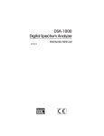
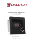
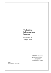
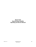
1
Technical
Information
Manual
Revision n. 4
14 June 2004
MOD. N968
SPECTROSCOPY
AMPLIFIER
MANUAL REV.4
NPO:
00100/03:N968x.MUTx/04
CAEN will repair or replace any product within the guarantee period if the Guarantor declares that
the product is defective due to workmanship or materials and has not been caused by
mishandling, negligence on behalf of the User, accident or any abnormal conditions or
operations.
CAEN declines all responsibility for damages or injuries
caused by an improper use of the Modules due to
negligence on behalf of the User. It is strongly
recommended to read thoroughly the CAEN User's
Manual before any kind of operation.
CAEN reserves the right to change partially or entirely the contents of this Manual at any time
and without giving any notice.
Document type:
User's Manual (MUT)
Title:
Mod. N968 Spectroscopy Amplifier
Revision date:
14/06/2004
Revision:
4
TABLE OF CONTENTS
1.
GENERAL DESCRIPTION ..........................................................................................................................................4
1.1
2.
3.
OVERVIEW...............................................................................................................................................................4
TECHNICAL SPECIFICATIONS ...............................................................................................................................5
2.1
PACKAGING.............................................................................................................................................................5
2.2
POWER REQUIREMENTS.......................................................................................................................................5
2.3
FRONT AND BACK PANEL ....................................................................................................................................6
2.4
FRONT PANEL CONTROLS....................................................................................................................................7
2.5
INTERNAL JUMPERS..............................................................................................................................................8
2.6
FRONT PANEL DISPLAYS......................................................................................................................................9
2.7
INPUT /OUTPUT CONNECTIONS ..........................................................................................................................9
2.8
TECHNICAL SPECIFICATION TABLE .................................................................................................................10
FUNCTIONAL DESCRIPTION................................................................................................................................ 12
3.1
SHAPING DETERMINATION ...............................................................................................................................12
3.2
EQUIPMENT FACILITIES.....................................................................................................................................12
3.3
CIRCUIT DESCRIPTION........................................................................................................................................13
LIST OF FIGURES
FIG. 2.1: M OD. N968 FRONT AND BACK PANEL .............................................................................................................6
FIG. 2.2: M OD. N968 SIDE VIEW WITH JUMPERS LOCATION ........................................................................................8
FIG. 2.3: UNIPOLAR OUTPUT EQUIVALENT RMS NOISE VS. SHAPING TIME (TS).................................................11
FIG. 2.4: BIPOLAR OUTPUT EQUIVALENT RMS NOISE VS. SHAPING TIME (TS)....................................................11
FIG. 3.1: N968 CIRCUIT BLOCK DIAGRAM ......................................................................................................................13
FIG. 3.2: N968 I/O TIMING DIAGRAM ..............................................................................................................................14
LIST OF TABLES
TABLE 2.1: POWER REQUIREMENTS................................................................................................................................5
TABLE 2.2: M OD. N968 TECHNICAL FEATURES...........................................................................................................10
NPO:
00100/03:N968x.MUTx/04
Filename:
N968_REV4.DOC
Number of pages:
14
Page:
3
Document type:
User's Manual (MUT)
Title:
Mod. N968 Spectroscopy Amplifier
Revision date:
14/06/2004
Revision:
4
1. General description
1.1
Overview
The Mod. N968 is a spectroscopy amplifier implemented in a single-width NIM module. It
accepts the typical outputs generated from either optical feedback or resistor feedback
preamplifiers connected with nuclear particle detectors.
A front panel switch allows to select between positive and negative input signals.
Gain setting can be performed continuously in the 10 ÷ 1500 range, product of Coarse, Fine
and Superfine Gain. Two internal jumpers allow to set a x0.1 attenuation and a further x2
amplification, thus extending the gain range to 1 ÷ 3000.
Shaping time (Ts) values are 0.5, 1, 2, 3, 6, 10 µs.
The Pole Zero (PZ) cancellation is performed via a front panel screw-trimmer.
The module features also:
- a Bipolar output (to be used for timing purposes)
An advanced Baseline Restorer (BLR) circuit, with either manual or automatic threshold
setting
A Pile Up Rejector (PUR) which allows to reject piled up events
NPO:
00100/03:N968x.MUTx/04
Filename:
N968_REV4.DOC
Number of pages:
14
Page:
4
Document type:
User's Manual (MUT)
Title:
Mod. N968 Spectroscopy Amplifier
Revision date:
14/06/2004
Revision:
4
2. Technical specifications
2.1
Packaging
The Model N968 is housed in a single width NIM module.
2.2
Power requirements
Table 2.1: Power requirements
+12 V
-12 V
+24 V
-24 V
NPO:
00100/03:N968x.MUTx/04
Filename:
N968_REV4.DOC
200mA
200 mA
200 mA
Number of pages:
14
Page:
5
Document type:
User's Manual (MUT)
2.3
Title:
Mod. N968 Spectroscopy Amplifier
Revision date:
14/06/2004
Revision:
4
Front and back panel
Mod.
N968
SPECTROSCOPY
AMPLIFIER
SFG
UNI
BI
INPUT
CRM
FINE GAIN 0.5 - 1.5
100
200
50
500
20
1K
COARSE GAIN
2µs
BUSY
INH
RTP
LTC
3µs
1µs
6µs
0.5µs
10µs
SHAPING TIME
UNCOMP
PREAMP OUT
OVCOMP
AUTO
B
L
R
PZ ADJ
THR
-12V
9
NC
8
+24V
7
-24V
6
5
PRS
4
+12V
3
NC
2
CL_GND
1
A_GND
INPUT
DELAY
POS
ON
OFF
NEG
DC
UNI
BI
Fig. 2.1: Mod. N968 Front and back panel
NPO:
00100/03:N968x.MUTx/04
Filename:
N968_REV4.DOC
Number of pages:
14
Page:
6
Document type:
User's Manual (MUT)
2.4
Title:
Mod. N968 Spectroscopy Amplifier
Revision date:
14/06/2004
Revision:
4
Front panel controls
FINE GAIN:
10-turn precision potentiometer with graduated dial for continuously
variable direct-reading gain factor of x0.5 to x1.5.
COARSE GAIN:
6-position switch, selects feedback resistors for gain factors of 20, 50,
100, 200, 500, and 1k. Two Jumpers on the printed circuit board select
x0.1 attenuation and x2 Amplification (see § 2.5).
S.F. GAIN:
SUPERFINE GAIN, screwdriver adjustable potentiometer to adjust fine
gain; adjustment range: ±2.5 % of the FINE GAIN RANGE.
INPUT:
Locking toggle switch, selects either Pos (positive) or Neg (negative)
input pulse polarity.
SHAPING TIME:
6-position switch, selects time constants for active pulse-shaping filter
network from 0.5, 1, 2, 3, 6, and 10 µs.
PZ ADJ1:
Screwdriver adjustable potentiometer to set the pole-zero cancellation
to compensate input decay times from 40 µs to infinity.
DELAY:
Locking toggle switch, allows to set UNIpolar output either to prompt or
delayed 2 µs.
BLR:
3-position locking toggle switch, selects the source of control for the
gated baseline restorer discriminator threshold from:
−
Auto The BLR threshold is automatically set to an optimum level,
as a function of the signal noise, by an internal circuit.
−
PZ Adj Enables the PZ adjustment; the BLR threshold is
determined by the Auto function. The BLR time constant is also
greatly increased to facilitate the PZ adjustment.
−
Threshold The BLR threshold is manually set by the threshold
potentiometer in the 0 ÷ 300 mV range.
DC:
Screwdriver adjustable potentiometer to set the Unipolar Output DC
level; range ±100 mV.
1
The adjustment must be performed with a low rate input
NPO:
00100/03:N968x.MUTx/04
Filename:
N968_REV4.DOC
Number of pages:
14
Page:
7
Document type:
User's Manual (MUT)
2.5
Title:
Mod. N968 Spectroscopy Amplifier
Revision date:
14/06/2004
Revision:
4
Internal Jumpers
Some settings can be performed via internal jumpers (location is shown in Fig. 2.2).
Preamp Gain (sw4):
allows to set the input preamplifier stage gain either at x1 or
x0.1
PRS Polarity (sw3):
allows to configure the module in order to accept on the PRS
input either positive or negative pulses. If the preamplifier
connected to the N968 does not feature the PRS, set the
jumper to positive
G.A. Gain (sw1):
allows to introduce either a x2 or x1 gain factor at the Gated
Amplifier stage
Th. Symmetry (sw5):
allows to set the BLR negative threshold either symmetric
(equal to the BLR threshold) or asymmetric (BLT threshold +
300mV)
x2
sw1
x1
PRS POLARITY
NEG
POS
sw3
x1 x0.1
sw4
ASYMM
SYMM
sw5
Fig. 2.2: Mod. N968 side view with jumpers location
NPO:
00100/03:N968x.MUTx/04
Filename:
N968_REV4.DOC
Number of pages:
14
Page:
8
Document type:
User's Manual (MUT)
2.6
Title:
Mod. N968 Spectroscopy Amplifier
Revision date:
14/06/2004
Revision:
4
Front panel displays
PZ VISUAL INDICATOR: PZ Visual Indicator leading to high precision adjustment of the
pole-zero cancellation, for exact compensation of the decay
time of the preamplifier signal. Left LED signals
overcompensation, right LED under compensation. Setting the
BLR switch to the adjust position activates the PZ Visual
Indicator. Under compensation can be corrected by turning the
potentiometer clockwise, while over compensation requires the
potentiometer to be turned anti-clockwise. A correct Pole Zero
setting is signalled by the two LEDs off (or, at least, blinking
low).
2.7
Input/Output connections
INPUTS:
INPUT BNC front- and rear-panel connectors, accept either positive or
negative pulses with rise times of 10 to 500 ns and decay times of 40
µs to infinity;
if Preamp Gain = 1, Zin ≅ 1000 Ω DC-coupled / ≅ 500 Ω AC-coupled;
if Preamp Gain = 0.1, Zin ≅ 1000 Ω DC-coupled / AC-coupled
linear maximum: 1V (Preamp gain = 1, Amplifier gain = 10), 10 V (x01
attenuation selected); absolute maximum: 10 V.
Front-panel INPUT is provided with a test point.
RTP (Rise Time Protection) Rear-panel BNC connector (TTL signal,
50 Ω impedance), it is provided by the Multichannel Analyzer (MCA) to
communicate to the amplifier that the ADC lower level threshold is
exceeded and the signal has been accepted. It is used only in the Live
Time Corrector (LTC) circuit.
PRS Reset signal on the Rear-panel D-type 9 pin female connector.
OUTPUTS:
UNI Front-panel BNC connector with Z < 0.5 Ω and rear-panel
connector with Z = 93 Ω; short-circuit maximum duration: 10 s (Frontpanel), ? 8 (Rear-panel); full-scale linear range of 0 to +10 V; active
filter shaped; DC-restored; DC-level adjustable to ±100 mV.
Front-panel UNI output is provided with a test point.
BI Front-panel BNC connector with Z <1 Ω and rear-panel connector
with Z = 93 Ω; short-circuit maximum duration: 10 s (Front-panel), ? 8
(Rear-panel); prompt output with positive lobe leading and linear range
of ±10 V; active filter shaped.
Front-panel BI output is provided with a test point.
CRM Rear-panel BNC connector with Z <10 Ω provides a nominally +5
V, 100 ns logic pulse every time the input signal exceeds the baseline
restorer fast discriminator threshold.
INH Rear-panel BNC connector with Z <10 Ω provides a nominally
+5 V logic pulse (suitable for the MCA anticoincidence input) when the
internal pile-up rejection logic detects a distortion of the input signal due
NPO:
00100/03:N968x.MUTx/04
Filename:
N968_REV4.DOC
Number of pages:
14
Page:
9
Document type:
User's Manual (MUT)
Title:
Mod. N968 Spectroscopy Amplifier
Revision date:
14/06/2004
Revision:
4
to pile-up. Signals whose peak occurs when the INH signal is active
must be thus rejected.
BUSY Rear-panel BNC connector with Z <10 Ω provides a +5 V logic
pulse for the duration that the input pulse exceeds the baseline restorer
discriminator.
LTC Rear-panel BNC connector, provides a positive true TTL logic
signal that is used to stop the MCA time counter; this allows a precise
evaluation of the source actual rate.
PREAMP POWER Rear-panel D-type 9 pin female power connector; it
mates with captive and noncaptive power cords on almost all
preamplifiers. Contact assignment is shown in Fig. 2.1.
2.8
Technical specification table
Table 2.2: Mod. N968 Technical Features
Packaging
One unit wide NIM unit
Gain range
1 ÷ 3000
UNIpolar shape: quasi Gaussian, peaking time 2.4 Ts, pulse
width at 0.1% level equal to 2.9 times the peaking time
Bipolar shape: approximate derivative, time to crossover 3 Ts
Pulse shape
Integral non linearity
Temperature instability
(0 to 50°C)
<± 0.025% @ 2 µs shaping time
Gain: < ±50 ppm/°C.
DC level: UNIpolar output: < ±10 µV/°C
BIpolar output: < ±30 µV/°C
≤ ±3 ns at 2 µs Ts for 50:1 dynamic range
Bipolar crossover walk
Overload recovery
Recovers to within 2% of rated output from X300 overload in 2.5
nonoverloaded pulse widths using a gain of 1000 for UNIpolar
Output. Same recovery from X1000 overload for BIpolar
Spectrum broadening
Typical: <16% FWHM for a 60Co 1.33 MeV gamma line at 85% of
full scale for an incoming count rate of 103 to 105 counts/s
(Unipolar Output, 2-µs shaping)
Spectrum shift
Peak position typical shift: <0.024% for a 60Co 1.33 MeV gamma
line at 85% of full scale measured from 10 3 to 105 counts/s
(Unipolar Output, 2-µs shaping) (T.B.C.)
Equivalent noise
4 µV / 6 µV (RMS) for UNIpolar/Bipolar output for 3 µs shaping time
and coarse gain = 100
3.5 µV / 5 µV (RMS) for UNIpolar/Bipolar output for 3 µs shaping
time and coarse gain = 1000
[Fig. 2.3: Equivalent RMS Noise Vs. Shaping Time (Ts)]
NPO:
00100/03:N968x.MUTx/04
Filename:
N968_REV4.DOC
Number of pages:
14
Page:
10
Document type:
User's Manual (MUT)
Title:
Mod. N968 Spectroscopy Amplifier
Revision date:
14/06/2004
Revision:
4
Equivalent RMS Noise (µV)
UNIPOLAR OUT
9
8
7
6
5
4
3
2
1
0
Gain=1000
Gain=100
0
2
4
6
8
10
Ts (µs)
Fig. 2.3: UNIpolar Output Equivalent RMS Noise Vs. Shaping Time (Ts)
Equivalent RMS Noise (µV)
BIPOLAR OUT
10
9
8
7
6
5
4
3
2
1
0
Gain=1000
Gain=100
0
2
4
6
8
10
Ts (µS)
Fig. 2.4: BIpolar Output Equivalent RMS Noise Vs. Shaping Time (Ts)
NPO:
00100/03:N968x.MUTx/04
Filename:
N968_REV4.DOC
Number of pages:
14
Page:
11
Document type:
User's Manual (MUT)
Title:
Mod. N968 Spectroscopy Amplifier
Revision date:
14/06/2004
Revision:
4
3. Functional description
3.1
Shaping determination
The proper shaping time constant must be seen as the better compromise in order to
match high count rates requirements (which lead to small time constant) and good signalto-noise ratios (which lead to big values). For scintillation counters the energy resolution
depends largely on the detector (scintillator and photomultiplier), therefore a shaping time
constant of about four times the decay time constant of the scintillator is a reasonable
value.
Gas proportional counters usually have a collection time in the 0.5 ÷ 5 µs range, so a ~2 µs
time constant could provide a good resolution.
Instead, for surface barrier semiconductors, a time constant in the 0.5 ÷ 2 µs range is
recommended.
3.2
Equipment facilities
In order to provide the User with an equipment suitable for almost any spectroscopy
application, the Mod. N968 includes:
−
a Pile-up Rejector/Live Time Corrector (PUR/LTC) circuitry which allows operation with
minimal dependence on system count rate. The PUR circuit interrogates incoming
pulses for pile up and generates a signal that prevents the ADC from converting the
piled up events. The LTC circuit then generates a system dead time that extends the
collection time to compensate for the events lost due to pileup rejection. The result is
lower background, better resolution and accurate live time information for the best
possible analysis results.
−
a gated Baseline Restorer (BLR), which includes a discriminator that operates the
sensing circuits that normally establish the baseline reference of the Multichannel
Analyzer (MCA). Performance of the spectrometer depends on the precision of the
setting of the BLR threshold. Such automatic threshold control typically gives as good
or better results than those the most experienced operator could achieve manually.
−
a Pole Zero (PZ) Visual Indicator: a LED adviser which leads to high precision
adjustment of the pole-zero cancellation, for exact compensation of the decay time of
the preamplifier signal. Two LEDs indicate either over-compensation or undercompensation.
−
a Bipolar Output, which provides a zero-crossing pulse, suitable for precisely detecting
the radiation arrival time. In fact, the zero-crossing of the pulse occurs with a constant
delay with respect to the onset of the pulse, independently from the amplitude, thus
allowing to reduce time-walk effects.
−
an Inhibit Output, which provides a pulse when pile-up occurs. This pulse shall be
applied to the MCA’s anticoincidence input in order to prevent it from measuring and
storing a non-valid amplitude.
NPO:
00100/03:N968x.MUTx/04
Filename:
N968_REV4.DOC
Number of pages:
14
Page:
12
Document type:
User's Manual (MUT)
3.3
Title:
Mod. N968 Spectroscopy Amplifier
Revision date:
14/06/2004
Revision:
4
−
a Busy Output, which provides a pulse whose width is equal to the time the input pulse
exceeds the BLR discriminator level and is automatically extended by the generation
of an Inhibit signal.
−
a CRM (Count Rate Meter) Output, which generates a TTL signal every time a valid
input pulse arrives.
Circuit description
The input signal provided by the preamplifier is processed in the way described in the
Fig. 3.1 block diagram:
BIPOLAR
FILTER &
OUTPUT
STAGE
POLARITY
INPUT
GAIN
STAGES
INPUT
STAGE
BIPOLAR
OUTPUT
SHAPING
STAGE
UNIPOLAR
OUTPUT
STAGE &
DELAY
INPUT
ATTENUATOR
UNIPOLAR
OUTPUT
BASE LINE
RESTORER
POLE ZERO
VISUAL
INDICATOR
SLOW
DISC
BASELINE
BUSY
GATED
LOGIC
POLE ZERO
ADJUSTMENT
COUNT RATE METER
LIVE TIME CORRECTION
MANUAL
THRESHOLD
RISE TIME
PROTECTION
AUTO
THRESHOLD
FAST
DIFFERENTIATOR
FAST
DISC
PILE UP
DETECTION
LOGIC
INHIBIT
Fig. 3.1: N968 circuit block diagram
The amplifying chain is composed by a preamplifier (input stage) and the gain stages. The
coarse, fine and super-fine gain controls operate over these stages, allowing to set the gain
level. The polarity setting is performed through a stage which is configured either inverting
or non-inverting.
The subsequent shaping stage consists of a double 4-pole integrator which forms the pulse
semi-gaussian profile.
The chain composed by both the amplifying and the shaping stages is configured as
“gated-amplifier”, in order to compensate the amplifiers’ thermical drift and offsets, which
would lead to high gain levels saturation and output dynamics reduction.
The fast differentiator stage allows to acquire the pulse’s arrival time through a comparator
(fast discriminator), whose output is used also to form the Count Rate Meter (CRM) output.
Another comparator (slow discriminator) provides the BUSY output, operating directly over
the UNIpolar output.
The baseline restorer (BLR) also operates over the UNIpolar output, and its purpose is to
keep the baseline constantly at the level set through the DC control, in order to decouple
the pulse acquisition from the input rate.
NPO:
00100/03:N968x.MUTx/04
Filename:
N968_REV4.DOC
Number of pages:
14
Page:
13
Document type:
User's Manual (MUT)
Title:
Mod. N968 Spectroscopy Amplifier
Revision date:
14/06/2004
Revision:
4
The chain is completed by the UNIpolar output stage, the delay circuit and the BIpolar
forming and output stage.
The fast and slow discriminators thresholds can be set either manually or automatically; in
the latter case, a circuit provides the threshold value according to the UNIpolar output noise
level.
The gated-logic block manages the signals provided by the discriminators, the baseline
restorer and performs the pile-up rejection (PUR) and live-time correction (LTC).
The timing diagram in Fig. 3.2 shows the PUR function and the circuit response to a pulse
pile-up: the second pulse arrives before the circuit recovers from Busy, the Fast
Differentiator produces another signal that triggers the discriminator to update the Busy
output and to provide another CRM pulse. In the meantime, at the arrival of the second
pulse, a bistable, set by the first pulse, produces the Inhibit output.
The LTC function is also shown in Fig. 3.2: after a piled-up event detected and then rejected
by the MCA (with the subsequent production of the RTP signal, which communicates that
the output has exceeded the MCA internal threshold), the LTC signal is produced and kept
active until the next RTP. While the LTC signal is active, the MCA halts its internal time
counter, thus allowing to obtain a correct input rate value (the greater the number of pulses,
the better the rate value measure): in fact the live time measured by the MCA will be
obtained by subtracting the MCA dead time and the time the LTC is active from the total
time. In this way the source actual rate will be equal to the ratio between the number of
converted pulses and the live-time.
3rd event
2nd event
1st event
N968 INPUT
SHAPERS
INPUT
distortion
due to
pileup
UNIPOLAR
OUTPUT
FAST DIFF.
OUTPUT
CRM
OUTPUT
BUSY
OUTPUT
INHIBIT
OUTPUT
LTC
OUTPUT
MCA RTP
OUTPUT
Fig. 3.2: N968 I/O timing diagram
NPO:
00100/03:N968x.MUTx/04
Filename:
N968_REV4.DOC
Number of pages:
14
Page:
14