1
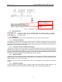
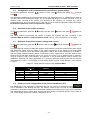
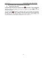
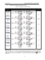
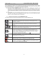
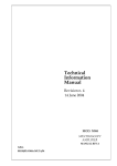
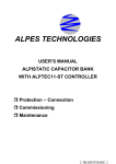
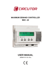
REACTIVE ENERGY REGULATORS computer MAX 6f 12Vdc computer MAX 12f 12Vdc Instruction Manual (M066B01-03-15B) M066B01-03-15B computer MAX 6f 12Vdc- MAX 12f 12Vdc -1- M066B01-03-15B computer MAX 6f 12Vdc- MAX 12f 12Vdc Table of Contents__ __________________________________________________ 1 INTRODUCTION AND SAFETY TIPS ......................................................................................................... 3 1.1 CHECKS TO BE CARRIED OUT WHEN THE REGULATOR IS RECEIVED .................................................................. 3 1.2 START-UP SCREEN ........................................................................................................................................... 4 1.3 DEFINITIONS .................................................................................................................................................... 4 1.3.1 4-Quadrant Regulator. .......................................................................................................................... 4 1.3.2 FCP System (FAST Computerized Program). ....................................................................................... 4 1.3.3 Stages and Steps .................................................................................................................................... 4 1.3.4 Regulation Program. ............................................................................................................................. 4 2 GENERAL FEATURES ................................................................................................................................... 5 3 FRONT PANEL: SCREEN AND KEYBOARD............................................................................................. 6 3.1 SCREEN ........................................................................................................................................................... 7 3.2 PARAMETER MEASUREMENT ........................................................................................................................... 7 3.3 ERRORS AND ERROR MESSAGES ................................................................................................................... 7 3.4 MODES OF THE UNIT AND BUTTON FUNCTIONS ................................................................................................ 8 3.4.1 Keypad functions in normal WORKING mode ...................................................................................... 8 3.4.2 Keypad functions in normal CONFIGURATION mode ........................................................................ 8 4 INSTALLATION AND START-UP ................................................................................................................ 9 4.1 TECHNICAL FEATURES ..................................................................................................................................... 9 4.2 UNIT INSTALLATION ...................................................................................................................................... 10 4.2.1 Mechanical Installation....................................................................................................................... 10 4.2.2 Connections ......................................................................................................................................... 10 4.2.3 Cable cross-sections and protection elements .................................................................................... 11 4.2.4 Wiring diagrams.................................................................................................................................. 11 5 CONFIGURABLE PARAMETERS OF THE REGULATOR ................................................................... 12 5.1 5.2 5.3 5.4 5.5 5.6 5.7 5.8 6 TARGET COS Φ ............................................................................................................................................... 12 CURRENT OF THE SMALLEST CAPACITOR STEP ............................................................................................... 12 CALCULATION OF THE C/K FACTOR .............................................................................................................. 13 POWER CONFIGURATION OF THE STAGES OR CONFIGURATION PROGRAM: ..................................................... 13 CONFIGURATION OF THE CONNECTION AND RECONNECTION SYSTEM DELAYS: ............................................. 14 SELECTION OF THE NUMBER OF STAGES......................................................................................................... 14 SELECTION OF THE PHASE BETWEEN VOLTAGE AND CURRENT. ...................................................................... 14 PRIMARY CURRENT CONFIGURATION OF THE CURRENT TRANSFORMER (CT)................................................. 14 DEVICE MENU AND CONFIGURATION PROCEDURE. ...................................................................... 15 6.1 ENTERING THE SETUP MENU. ......................................................................................................................... 15 6.2 DIAGRAM FOR NAVIGATING THROUGH THE MENUS. ...................................................................................... 16 7 WORKING MODE ......................................................................................................................................... 17 7.1 FUNCTIONS OF THE UNIT IN NORMAL WORKING MODE ............................................................................... 17 7.2 BEHAVIOUR OF THE UNIT DURING ALARM MODE ........................................................................................ 18 8 MAINTENANCE ............................................................................................................................................ 18 9 TECHNICAL SERVICE ................................................................................................................................ 18 -2- M066B01-03-15B 1 computer MAX 6f 12Vdc- MAX 12f 12Vdc INTRODUCTION AND SAFETY TIPS CIRCUTOR S.A. thanks you for choosing one of the regulators from the Computer MAX series. These units have been built with state-of-the-art technologies, including a powerful processor that can calculate the optimum algorithms and achieve the best correction of the cos φ. The units comply with the EN 61010 Electrical Safety Standard, in accordance with the Low Voltage Directive requirements (LVD 73/23/EC), as well as the EMC Directive (2004/108/EC) and are, therefore, certified for use with the CE mark. The purpose of this user manual is to describe the operating principles of the regulators of the Computer MAX series and to define the installation, start-up, and operation procedures. Safety The installation and maintenance of the unit must be performed by qualified and authorised staff, in compliance with the national and international Standards. Handling or use of the unit different from that specified by the manufacturer may compromise user safety. The main switch must be disconnected before any maintenance is performed on the cos φ regulation units. After a disconnection, wait at least 5 minutes to make sure that all capacitors have been suitably discharged. The following safety precautions must be taken into account during installation, maintenance or start-up operations on units regulated by a computer Max: Make sure that the units have the corresponding earthing connections before they are connected. A faulty earthing connection could lead to a faulty operation and represent the risk of electrical discharge to the user or person handling the unit. The necessary precautions will be taken during maintenance operations to prevent the risk of electrocution and electric shock. Make sure that the unit has been disconnected and wait until the capacitors have been fully discharged before handling or operating the unit. We recommend the use of safety goggles and gloves. Resonance can be produced when the power factor compensation units are connected with no loads. In this case, the voltage harmonics can be amplified, causing damage to the power factor compensation units and other units connected to the network. Follow the start-up and stop procedures described in the manual to prevent damage to the unit and/or adjacent units. Always use original spare parts or components when adjusting or replacing components and follow the corresponding procedures described in the instruction manual. 1.1 Checks to be carried out when the regulator is received On receiving the regulator, check that: The unit has not been damaged during transport. The type supplied is the same as that requested. (See label on the rear, Fig. 1.1) Check the features shown on the unit's label, to make sure that they are valid for the type of grid where the unit will be connected. (Voltage and power supply frequency, measurement range, etc.) Follow the instructions described in section 3, in relation to the rest of the installation and setup. Please contact the technical-commercial service of CIRCUTOR, S.A. if you detect any anomalies. -3- M066B01-03-15B computer MAX 6f 12Vdc- MAX 12f 12Vdc Power supply and measured . frequency 50 or 60 Hz indifferently Features of the outputs Fig. 1.1.- Rear label of the unit 1.2 Start-up Screen A start-up screen will be displayed when the computer MAX is powered, showing the unit's version. This information must be included when reporting any fault or defect 1.3 Definitions The following definitions may be useful to understand some of the sections in this manual 1.3.1 4-Quadrant Regulator. The regulator is capable of performing the measurement and regulation functions when the active power is transferred from the mains to the loads (common case in a consumer installation) or when the load is transferred to the mains (in the case of installations with generators that not only allow the consumption of energy, but can also export or sell energy). 1.3.2 FCP System (FAST Computerized Program). This system controls the connection sequence of the different stages, tending to minimise the number of operations and matching the usage times of the different stages to achieve the determined final power demand. The operations are carried out in such a way that, in the case of stages with an identical power, the stage that has been disconnected the longest is connected when there is demand and the stage that has been connected the longest is disconnected in the case of a surplus. 1.3.3 Stages and Steps A distinction must be established between stages and steps. In this manual, a STAGE is described as the capacitor banks in which the power factor compensation unit is divided and that may have different power ratings, usually in 1:1, 1:2, 1:2:4, etc. ratios. A step is each one of the total power fractions that can be regulated by using stages with different weights. 1.3.4 Regulation Program. The power ratings of the different groups or stages usually follow certain patterns called "programs”. The program indicates the power ratios between different stages. The most frequent programs are: -4- M066B01-03-15B computer MAX 6f 12Vdc- MAX 12f 12Vdc Program 1:1:1 All stages have the same power rating. For example, a 100 kvar unit with 5 steps would be composed of 5 identical 20 kvar stages and would be described as a (5 x 20) kvar unit. Program 1:2:2:. Starting with the second stage, each stage has twice as much power as the first stage. For example, a 180 kvar unit with 5 stages would be composed of a first 20 kvar stage and 4 identical 40 kvar stages, and so it could be described as a (20 + 4 x 40) kvar unit. Program 1:2:4 The second stage has twice as much power as the first stage and the remaining stages after the second stage have four times as much power as the first stage. For example, a 300 kvar unit with 5 stages would be composed of a first 20 kvar stage, a second 40 kvar stage and 3 identical 80 kvar stages, and so it could be described as a (20 + 40 + 3 x 80) kvar unit. Other Programs. Other programs can be used, such as 1:2:4:8 or 1:1:2:2, etc. The numbers, as can be deduced from the preceding cases, give the power ratio between the first stage, which receives a value of 1, and the subsequent stages (2 means twice as much power, 4 means four times as much power, etc.). The unit comes equipped with a program called P00 that simulates and displays the number of steps that would be connected on the screen, without actually connecting them. It is used to see the unit's behaviour in safe mode. 2 GENERAL FEATURES computer MAX 6f 12Vdc / 12f 12Vdc reactive energy regulators measure the network cos φ and regulate the connection and disconnection of capacitors to correct it. Type Computer Max 6f 12Vdc Computer Max 12f 12Vdc Maximum no. outputs 6 outputs 12 outputs Here are some of the most important features of this series of regulators: - FCP system that minimises the number of capacitor connections and disconnections. A wide variety of programs 1:1:1, 1:2:2, 1:2:4, 1:1:2:2, etc. This enables breaking down the total power into up to 31 steps in the computer MAX 4-quadrant control (see Fig.2.1), with indication about the connected stages, indication of the cos φ, power and reactive power signs (inductive or capacitive ) THREE-digit LCD screen with seven segments and over 20 icons for identifying different operating conditions. Easy configuration, with only three buttons and without having to disconnect the power supply. Use of the 50 or 60 Hz frequency, indifferently. Display of all measurements on a single screen. Easy mounting without tools. Dimensions in compliance with DIN 43 700 (144 x 144 mm front panel) Voltage measurement circuit and power supply on a single input. 4-quadrant regulation (importing or exporting power installation) -5- M066B01-03-15B computer MAX 6f 12Vdc- MAX 12f 12Vdc Fig. 2.1.- Signs in 4-quadrant measurements 3 FRONT PANEL: SCREEN AND KEYBOARD The regulator's front panel shows the following signals: Front Panel Configurable Parameters Measurable parameters Fig. 3.1.- Front panel of the unit NOTE: There is a detailed description of the configuration process, the different parameters and CONFIGURATION section ( 6) regulation modes -6- in the Navigation buttons M066B01-03-15B 3.1 computer MAX 6f 12Vdc- MAX 12f 12Vdc Screen The regulator screen is a three-digit LCD with seven segments. It also has several icons that provide information about the regulator state, such as indicating the value of the cos φ, the reactive power sign (inductive or capacitive ), signals for the connected stages, and various parameter measures (see section 3.2) Icons Screen and LEDs In the NORMAL or WORKING mode, the RUN LED is lit and the cursor indicates the parameter being measured (Left list) Inductive reactive power Capacitive reactive power (red) lights The LED up during normal operation In the CONFIGURATION mode, the RUN LED is off and the cursor is blinking, indicating the parameter being adjusted (Right list). The LED shows that current I or the Imax shown on the display must be multiplied by 10 3.2 Indicating Icons Symbols indicating the connected capacitors (only in NORMAL mode) Parameter measurement During the normal operating mode, the regulator measures the following parameters: cos, mains current, THD of the network current and network voltage. The section also shows the maximum values of the current and network voltage from the previous parameter reset. The measured parameter can be changed with the navigation arrows and is indicated by the cursor 3.3 Errors and ERROR Messages If the unit detects and error, a code appears on the screen indicating the type of error detected. The errors that can be detected and the messages displayed on the screen are summarised in Table 3.1. Table 3-1: Errors and messages displayed on the screen ERROR message Description Load current below minimum or current transformer not connected. Appears if Isec<0.05 A Overcompensation. A disconnect request is made and all the stages are disconnected. Undercompensation. A connection request is made and all the stages are connected. Overcurrent. The current measured exceeds the nominal current by + 20 %. The nominal current is considered to be that of the CT primary Overvoltage. The measured rated voltage exceeds the nominal voltage by 15 % or more.. -7- M066B01-03-15B 3.4 computer MAX 6f 12Vdc- MAX 12f 12Vdc Modes of the unit and button functions The Computer MAX 6f 12Vdc / 12f 12Vdc regulators can operate in two modes: Normal or Working mode: This is the normal operating mode of the regulator. In this mode, the regulator measures the cos φ of the installation and automatically regulates the connection and disconnection of the capacitors to correct it. The regulation method depends on the adjustments entered in the configuration mode. Configuration or Adjustment mode: This mode is for configuring the working parameters of the regulator. Use a long keystroke of the button to enter this mode. After entering this mode, the regulator progressively disconnects all the capacitors, stops regulating and admits changes to the adjustments The navigation buttons have different functions, depending on the mode the regulator is in. 3.4.1 Keypad functions in normal WORKING mode Keypad for entering the configuration mode: After a long keystroke of this button (more than 1 s) the unit changes to the configuration mode Manual capacitor connection: When the button is pressed down and held (more than 1 s), the regulator begins sequentially connecting steps in time intervals of 1 s. Manual capacitor disconnection: Long Keystroke (more than 1 sec), the regulator begins sequentially disconnecting steps in 1 s intervals. 3.4.2 Keypad functions in normal CONFIGURATION mode Long Keystroke (more than 1 s): Enters and exits the configuration mode. The configured parameters are only saved after a long keystroke of the button. Short Keystroke: Enter / Exit the configuration option (different configurable parameters). Attention! The programmed values are not saved if a long keystroke with this button is not done when the configuration is finished Navigates upwards in the configurable parameters menu. Increases the digits during parameter configuration. Navigates downwards in the configurable parameters menu. Decreases the digits during parameter configuration. Changes the digit being configured (if the parameter has more than 2 digits). Disabling / Enabling Alarms: If the two buttons are pressed simultaneously, the + long or enabled message of the current regulator shows a disabled fault, overcompensation and undercompensation alarms (Section 3.3). Once they are disabled, the corresponding error messages will no longer appear in the unit. -8- M066B01-03-15B 4 computer MAX 6f 12Vdc- MAX 12f 12Vdc INSTALLATION AND START-UP This section contains information and warnings that the user must respect at all times to guarantee his/her own safety and the safe operation of the unit. WARNING! The Computer MAX 6f 12Vdc / 12f 12Vdc regulators are connected to units with capacitors that remain charged even after the voltage has been disconnected. Wait at least 5 minutes after the unit has been disconnection, before the internal components of the equipment are handled, in order to avoid the risk of electric shock. Handling or use of the unit other than that specified by the manufacturer may compromise user safety. The power supply must be disconnected from the unit when it shows signs of deterioration or faulty operation. In this case, contact a qualified service representative. The persons responsible for the installation or operation of the Computer MAX 6f 12Vdc / 12f 12Vdc regulator must follow common electrical installation safety measures for LV or MV installations to guarantee a safe operation, depending on the installation location. In addition, they must take into account all warnings found in this instruction manual. 4.1 Technical features The main features of the unit are marked on the label on the rear (see Fig. 1.2) and they are also summarised in following the table. Power supply and measured voltage (Terminals C-D) Power supply cables Power circuit protection Current measurement circuit. (Terminals A-B) Current measurement circuit cables Current measurement margin Measurement accuracy Cos setting range Maximum consumption Screen Output Reference standards Safety/Insulation Protection degree Admissible environmental conditions Control system 400 +15% -10%; 45-65 Hz, (see label) It is best to connect to phases L2-L3. 1.5 mm2 cross-section With a gl type 0.5 to 2A fuse External current transformer (CT), In /5 ratio. It is best to connect to phase L1. Minimum 2.5 mm2 cable cross-section. For distances greater than 25 m between the regulator and CT, it is recommended to increase the cross-section to 1 mm2 for every 10 m, or use a CT with a higher primary In 0.05 to 5 A (maximum overload +20%) Voltage and current: 1%; cos : 2 % 1 digit 0.85 ind. A 0.85 cap, Default setting: 1 computer MAX 6f 12Vdc : 400 V: 6,5 VA computer MAX 12f 12Vdc : 400 V: 7,5 VA 1 line x 3 digits x 7 segments + 20 icons Isolated voltage. 12±2 Vdc , Max 20 mA EN 61010, EN 61000-3-2, EN 61000-3-3, EN 61000-4-2, EN 61000-4-4, EN 61000-4-8, EN 61000-4-5, EN 61000-4-11, UL 94 Category III installation, as per EN 61010-1 Double-insulation electric shock protection, (class II unit) as per EN 61010-1 IP40 (unit mounted, cabinet front panel) IP30 (unit not mounted), according to EN-60529 Temperature: -20ºC to +60ºC; Relative humidity: max 95% (noncondensing). Max. altitude: 2000 m FCP (Program that minimises the number of operations) Total (Connection/Disconnection of all required capacitors) -9- M066B01-03-15B 4.2 computer MAX 6f 12Vdc- MAX 12f 12Vdc Unit installation 4.2.1 Mechanical Installation In mechanical terms, the unit is installed on the front panel of a cabinet or on a panel. The panel fixing drill must be drilled in compliance with DIN 43 700, (dimensions: 138+1xx138+1 mm). 4.2.2 Connections The following points must be checked before the unit is powered: The installation and maintenance of the unit must be performed by qualified and authorised staff, in accordance with the national and international Standards. All connections must remain inside the electric panel. Take into account that when the unit is connected, the terminals may be hazardous to the touch, and opening the covers or removing elements may expose these parts. Do not use the unit until its installation is completed. This regulator has a series of associated capacitor banks that remain charged up to 5 minutes after the unit has been disconnected from the mains. Make sure that all capacitors have been discharged before handling the unit. The installation of an external current transformer (CT) is necessary to measure the current. Usually, the transformation ratio of this CT is In/5 A, where In must be a minimum of 1.5 times over the total maximum current of the load. The current transformer (CT) must be installed on the distribution panel where all of the load currents circulate and where the current of the capacitors will be compensated (see Fig. 4.1) The current transformer (CT) should preferably be connected to phase L1, while the voltage connections should be connected to phases L2 and L3 (see diagrams in Fig. 4.2 and 4.3). Connections P1, P2, S1 and S2 shown on the said diagrams must be respected. If the connection layout mentioned above is not respected, the phase must be adjusted, following the procedure in section 5.1.7. CORRECT INCORRECT The current transformers (CT) must measure the combined current of the capacitors and the loads If this does not work, make sure that the CT is not shortcircuited. When the CT is connected in this position, NO CAPACITORS WILL BE CONNECTED, even when inductive loads are present. The unit does not perform the compensation functions. When the CT is connected in this position, ALL CAPACITORS WILL BE CONNECTED. However, they will not be disconnected when the load decreases. Risk of overcompensation in the network with no load Fig. 4.1.- Location of the current transformer - 10 - M066B01-03-15B 4.2.3 computer MAX 6f 12Vdc- MAX 12f 12Vdc Cable cross-sections and protection elements The power circuit must be protected with gl (IEC 269) or M type fuses (IEC 127) with a rating of 0.5 to 2 A. A circuit breaker or equivalent device must be used to connect and disconnect all of the unit's control circuits from the power supply network. The switch must be installed on the unit and be easy to access. The power circuit and voltage circuit must be connected with cables that have a minimum cross-section of 1.5 mm2. The secondary cables of the current transformer (CT) must have a minimum cross-section of 2.5 mm2. For distances between the CT and the regulator greater than 25 m, this cross-section must be increased by 1 mm2 for every 10 m. 4.2.4 No C D A B 1 2 3 4 Wiring diagrams Description of the terminals Power supply Power supply Current input S1 Current input S2 Negative outputs Output 1 Output 2 Output 3 Outpu 4 No 5 6 7 8 9 10 11 12 Description of the terminals Output 5 Output 6 Output 7 ( computer MAX 12f 12Vdc) Output 8 ( computer MAX 12f 12Vdc) Output 9 ( computer MAX 12f 12Vdc) Output 10 ( computer MAX 12f 12Vdc) Output 11 ( computer MAX 12f 12Vdc) Output 12 ( computer MAX 12f 12Vdc) Fig. 4.2.- Connection diagram Computer MAX 6f 12Vdc / 12f 12Vdc - 11 - M066B01-03-15B 5 computer MAX 6f 12Vdc- MAX 12f 12Vdc CONFIGURABLE PARAMETERS OF THE REGULATOR A series of parameters must be programmed to adjust the regulator to the installation where the cos will be regulated. The programmable parameters and configuration procedure are described below. See section 3.5.2 for selecting the different configuration options. The following parameters can be configured: 5.1 Target cos φ To adjust this parameter, press the press buttons until the cursor points to the option and then This parameter is used to fix the desired power factor for the installation. The regulator will add the number of capacitors needed to adjust the value as close as possible to the target value. The regulation process is carried out in stages so that it will not affect any switching operations until the noncompensated demand is at least 70% of the power of the smallest stage or the excess compensation is 30% of the power of the smallest stage. Any value between 0.85 Inductive and 0.95 Capacitive can be configured. 5.2 Current of the smallest capacitor step To adjust this parameter, press the press buttons until the cursor points to the option and then This parameter is adjusted with the reactive current supplied by the smallest capacitor step, measured on the current transformer's (CT) secondary. Its adjustment value will depend on the power of the smallest capacitor step, the CT ratio and the network voltage. Table 5.1 shows the values that must be used to adjust the C/K for a 400 V network between phases, the different transformer ratios and the power ratings of the smallest stage. In the case of other voltages or conditions that have not been included in the table, the C/K value can be obtained with a simple calculation, as shown in section 5.1.3 Table 5-1.- C/K Factor, in accordance with the power of the smallest stage and current transformer (CT) ratio CT Ratio (p/Is) 150/5 200/5 250/5 300/5 400/5 500/5 600/5 800/5 1000/5 1500/5 2000/5 2500/5 3000/5 4000/5 Power in kvar of the smallest stage, in kvar, at 400 V (*) 2.5 0.12 0.09 0.07 0.06 0.05 5.00 0.24 0.18 0.14 0.12 0.09 0.07 0.06 7.5 0.36 0.27 0.22 0.18 0.14 0.11 0.09 0.07 0.05 10.0 0.48 0.36 0.29 0.24 0.18 0.14 0.12 0.09 0.07 0.05 12.5 0.60 0.45 0.36 0.30 0.23 0.18 0.15 0.11 0.09 0.06 15.0 0.72 0.54 0.43 0.36 0.24 0.22 0.18 0.14 0.11 0.07 0.05 20.0 0.96 0.72 0.58 0.48 0.36 0.29 0.24 0.18 0.14 0.10 0.07 0.06 0.05 25.0 0.90 0.72 0.60 0.48 0.36 0.30 0.23 0.18 0.12 0.09 0.07 0.06 30.0 37.5 40.0 50.0 60.0 75.0 80.0 0.87 0.72 0.58 0.45 0.36 0.27 0.22 0.14 0.11 0.09 0.07 0.05 0.90 0.67 0.54 0.45 0.33 0.27 0.18 0.13 0.10 0.09 0.06 0.96 0.72 0.54 0.48 0.36 0.29 0.19 0.14 0.12 0.10 0.07 0.87 0.72 0.60 0.45 0.36 0.24 0.18 0.14 0.12 0.09 0.87 0.72 0.54 0.43 0.29 0.22 0.17 0.14 0.11 0.90 0.68 0.54 0.36 0.27 0.22 0.18 0.14 0.96 0.72 0.57 0.38 0.28 0.23 0.19 0.14 (*) For other network voltages, the factor in the table, Vnom, must be multiplied by the ratio (400/Vnom) IMPORTANT!: When the C/K adjustment is too low, there will be a series of continuous connections and disconnections with minor load variations. (The system performs more operations than those actually needed). When the C/K adjustment is configured a little high (10%), the regulator needs demand or higher reactive excess for switching and performs fewer switching operations. - 12 - M066B01-03-15B 5.3 computer MAX 6f 12Vdc- MAX 12f 12Vdc Calculation of the C/K Factor In the case of values that have not been included in the table, the C/K factor can be calculated as follows: The smallest reactive power of the capacitor, Q, and the network voltage, V, must be known. The current Q of this capacitor will be then calculated as I C 3 .V The transformation ratio of the current transformer must also be known. This is called the K factor: K I prim / I sec where: I prim Iprim is the nominal current of the transformer's primary (for example, in a 250/5 it would be I sec 250A) is the transformer's secondary current. Usually 5A Therefore, the C/K factor will be: C/K IC K Q 3 .K .V Example: In a 500 V unit, the smallest capacitor is 60 kvar with a current transformer having a ratio of 500/5, and the calculation would be done as follows: K factor K 500 / 5 100 60.1000 Current of the smallest capacitor IC 69,28 A 3.500 Ic 69,28 C/K value C/K 0,69 100 K 5.4 Power configuration of the stages or configuration program: To adjust this parameter, press the buttons until the cursor points to the option press While making the adjustment, the screen switches between the options T1 to T6 and the cos and then The capacitor banks are composed of stages with different power ratings. Taking the lowest power stage as base power (1), the powers of the rest of the stages are given in relation to the first. Therefore, the following programs would be available: Program 1:1:1… All stages have the same power rating as the first stage. Program 1:2:2… After the second stage, all capacitors have a power rating that is twice as much as that of the first stage. Program 1:2:4… The second stage has twice the power and the subsequent stages have a four times the power rating of the first step. There are two types of actions in the same program, the FCP, which minimises the number of connections and disconnections, and the Total, which simultaneously connects and disconnects all the necessary steps. The programs available in the computer MAX f are listed in Table 5.2. The unit comes configured with P00 by default. This program displays the steps that should be connected in each situation on the screen, but does not actually connect them. Table 5-2.- Programs available in the computer MAX Screen Display P00 111 122 124 248 112 T11 T22 T24 T48 T12 C-Stage Power Ratio Simulator Program 1:1:1:1:1…. 1:2:2:2:2…. 1:2:4.4:4…. 1:2:4:8:8…. 1:1:2:2:2…. Total 1:1:1:1:1…. Total 1:2:2:2:2…. Total 1:2:4.4:4…. Total 1:2:4:8:8…. Total 1:1:2:2:2…. - 13 - M066B01-03-15B 5.5 computer MAX 6f 12Vdc- MAX 12f 12Vdc Configuration of the connection and reconnection system delays: To adjust this parameter, press the press buttons until the cursor points to the option and then This parameter establishes the unit's actuation times. The adjustment time, Tc, establishes the delay to connect or disconnect subsequent stages. The unit enables adjusting the Tc within the range of 2 to 99 network cycles. The time of the network cycle depends on the frequency, for example, for a 50 Hz network frequency, one cycle equals 20 ms. Note that this is the time the capacitors need to discharge. By default the parameter comes configured for 5 cycles. 5.6 Selection of the number of stages. To adjust this parameter, press the press buttons until the cursor points to the option and then The option enables programming the number of outputs the regulator will have. According to the computer MAX 6f 12Vdc or computer MAX 12f 12Vdc version can be configured 6 or 12 stages. 5.7 Selection of the phase between voltage and current. To adjust this parameter, press the press buttons until the cursor points to the option and then This parameter can be used to adapt the regulator to the different connection options of the power supply and measuring cables, and the cables of the current transformer to the phases of the three-phase system. Fig. 4.2 and 4.3 show the default configuration. That is, the current transformer is on phase L1 and the voltage measure between phases L2 (terminal C) and L3 (terminal D). It is often hard to check whether the unit has been wired like this or not, and so one of the T1 to T6 options shown in Table 5.3 must be chosen to cater to this situation. The selection of one of these options must be made in the installation, assuming that, during adjustment, it is consuming inductive reactive power with an inductive cos between 0.7 and 1. It is necessary to keep testing options until the screen displays a cos between 0.7 and 1 Table 5-3.- Phase selection options in the computer MAX Screen T1 T2 T3 T4 T5 T6 5.8 Phase shift V-I to cos = 1 30º 270º 150º 210º 90º 330º V Measurement phases L3-L2 L3-L2 L3-L2 L3-L2 L3-L2 L3-L2 CT Connection Phase L3 L1 L2 L3 (Inverted Transformer) L1 (Inverted Transformer) L2 (Inverted Transformer) Primary current configuration of the current transformer (CT). The adjustment for this parameter is selected at the end of the menu by marking the option . This is indicated by the blinking red LED. The primary current of the CT must be configured in this parameter, in accordance with the CT that has been installed for measuring the current of the installation. The adjustment range is 0 to 999, which with the x10 factor allows a transformer primary of up to 9990 A. The CT secondary comes with a default configuration of 5 A - 14 - M066B01-03-15B 6 6.1 computer MAX 6f 12Vdc- MAX 12f 12Vdc DEVICE MENU AND CONFIGURATION PROCEDURE. Entering the setup menu. To enter the setup menu of the unit, press and hold button for more than 1 s. (This is called a long keystroke in table 6.1, which gives a summary of the adjustment procedure). The pointer begins to select the flashing and points to the parameter that is going to be adjusted. Use buttons parameter to be adjusted. The unit only switches to adjustment or configuration mode if all the capacitors are disconnected. must be pressed and held down during the full capacitor disconnection Otherwise, the button sequence, which will be done with 1 s delays. After the disconnection process ends, the regulator enters the adjustment menu. The navigation diagram can be found in Table 6.1 and the details on the adjustable parameters and their adjustment possibilities are shown in Section 5.1. - 15 - M066B01-03-15B 6.2 computer MAX 6f 12Vdc- MAX 12f 12Vdc Diagram for navigating through the menus. Table 6-1.- Setup Menu navigation diagram Parameter selection Screens Refer to Section Long keystroke for entering cos objective 5.1 Home screen 5.2 5.3 C/K 5.4 Program Delays 5.5 No. of stages 5.6 CT phase 5.7 Primary of the CT 5.8 IMPORTANT: Once in the setup menu, if no buttons are pressed during three minutes, the unit exits the adjustment mode and changes to the normal mode without saving the configured parameters. To exit the setup menu of the unit and save the parameters, it is necessary to press and hold button for more than 1 sec.. - 16 - M066B01-03-15B 7 computer MAX 6f 12Vdc- MAX 12f 12Vdc WORKING MODE After completing the installation and the adjustments described in the previous sections, the unit can be set to the WORKING mode. The unit selects this mode by default after start-up and a brief moment while the processor is initialised. Two situations could appear in said mode: a) No alarm, Normal WORKING mode: In this case, the unit regulates the connection and disconnection of the capacitor stages according to the needs of the installation and the screen shows the cos of the installation by default. By pressing certain buttons, the different parameters can be measured and capacitor connection or disconnection can be forced, as shown in Section 7.1. b) Alarm mode: If any of the anomalies indicated in Section 3.2 occur, the unit shows an error code and steps to the alarm mode. Depending on the type of error, the unit can disconnect all the stages or continue regulating within its possibilities. 7.1 Functions of the unit in normal WORKING mode The following functions can be executed when the unit is in normal WORKING mode: long Manual capacitor connection: When the button is pressed down and held (more than 1 s), the regulator begins sequentially connecting steps in time intervals of 1 second long Manual capacitor disconnection If the button is held down more than 1 s, the regulator disconnects the steps in sequence at time intervals of less than 1 second Display of the number of connected steps: If the two buttons are pressed simultaneously, the regulator shows the number of connected steps. Bear in mind the difference between steps and stages (Section 1.1) short Parameter measurement: If a short keystroke with this button is done, a sequence of screens are scrolled, showing the following parameters: (cos) , cosine of the installation; (I) , current; (THD), THD of the network current; (V) Network voltage; (I, MAX) Maximum value reached by the current; (I, MAX) maximum value reached by the voltage;. The parameter displayed is indicated with the cursor Parameter measurement: Scrolls through the same parameters indicated in the previous panel, but in reverse order short long MAX Keypad for entering the configuration mode: After a long keystroke of this button (more than 1 s) the unit changes to the configuration mode Button for erasing maximums: If a long keystroke is done with this button (more than 1 sec) when the cursor marks MAX, the unit resets the maximum values of I and V registered while operating. - 17 - M066B01-03-15B 7.2 computer MAX 6f 12Vdc- MAX 12f 12Vdc Behaviour of the unit during ALARM mode If the unit detects an error (see section 3.2) the error code will be shown on the screen and the response of the computer will act as indicated on table 7.1 Table 7-1: Unit errors and actuations ERROR message 8 Description Possible cause and computer response Lower current measure at the threshold (0.05A on the secondary CT) Possible causes: Low load or CT not connected. Overcompensation. A disconnect request is made and all the outputs are disconnected. Possible causes: C/K incorrectly adjusted Undercompensation. Connection is requested and all the outputs are connected. Possible causes: C/K incorrectly adjusted Overcurrent. The current measure exceeds Inom + 20%. Possible causes: C/K incorrectly adjusted Overvoltage. The voltage measure exceeds Vnom +15%. Possible causes: Bad voltage connection The unit shows the RUN LED and the screen with all the zeros flashing, and does not connect any output No outputs are connected. All the outputs remain connected except the alarm, if triggered (see section 3.3) The alarm output disconnects, if triggered (see section 3.3). The unit normally tries to regulate, although it could have a regulation error. The alarm output disconnects, if triggered (see section 3.3). The unit normally tries to regulate, although it could have a regulation error. MAINTENANCE The computer MAX 6f 12Vdc / 12f 12Vdc regulator does not require special maintenance. Try to avoid any type of adjustment, maintenance or repairs while the unit is open as much as possible. If this cannot be avoided, only qualified and trained staff should carry out these operations. Disconnect the unit from all power supplies before performing any connection modifications, relocation, maintenance or repair operations. If any operational faults in the unit or in its protection elements are suspected, remove the unit from service and make sure that accidental connection is not possible. The design of the unit makes it easy to replace in the event of a fault. 9 TECHNICAL SERVICE If you have any doubts about the operation of the unit or suspect any malfunction, contact our service staff at CIRCUTOR, S.A. CIRCUTOR, S.A. - After-Sales Service. Vial Sant Jordi, s/n 08232 -Viladecavalls (Barcelona) Tel. - 902 449 459 (Spain) Tel. - (+34) 93 745 29 00 (outside Spain) Fax. - 93 745 29 14 e-mail - [email protected] - 18 -