1
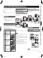
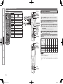
Graphical User Interface
Use this manual in combination with the
operating guide displayed on the GUI screen.
GUI Menu Operation (vpage 30)
GUI Menu Map (vpage 29)
Language (vpage 57)
Remote Control Unit Operations (vpage 108)
AV SURROUND RECEIVER
AVR-4810CI
Owner’s Manual
1.AVR4810CIEU_007.indd
1
2009/08/04
12:06:13
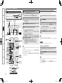
nSAFETY PRECAUTIONS
CAUTION
RISK OF ELECTRIC SHOCK
DO NOT OPEN
CAUTION:
TO REDUCE THE RISK OF ELECTRIC SHOCK, DO NOT REMOVE
COVER (OR BACK). NO USER-SERVICEABLE PARTS INSIDE.
REFER SERVICING TO QUALIFIED SERVICE PERSONNEL.
The lightning flash with arrowhead symbol, within an equilateral
triangle, is intended to alert the user to the presence of
uninsulated “dangerous voltage” within the product’s enclosure
that may be of sufficient magnitude to constitute a risk of electric
shock to persons.
The exclamation point within an equilateral triangle is intended
to alert the user to the presence of important operating
and maintenance (servicing) instructions in the literature
accompanying the appliance.
WARNING:
TO REDUCE THE RISK OF FIRE OR ELECTRIC SHOCK, DO NOT
EXPOSE THIS APPLIANCE TO RAIN OR MOISTURE.
1.
2.
3.
4.
5.
6.
7.
8.
9.
10.
11.
12.
13.
14.
15.
IMPORTANT SAFETY
INSTRUCTIONS
Read these instructions.
Keep these instructions.
Heed all warnings.
Follow all instructions.
Do not use this apparatus near water.
Clean only with dry cloth.
Do not block any ventilation openings.
Install in accordance with the manufacturer’s instructions.
Do not install near any heat sources such as radiators, heat registers,
stoves, or other apparatus (including amplifiers) that produce heat.
Do not defeat the safety purpose of the polarized or grounding-type plug. A
polarized plug has two blades with one wider than the other. A grounding
type plug has two blades and a third grounding prong. The wide blade or the
third prong are provided for your safety. If the provided plug does not fit into
your outlet, consult an electrician for replacement of the obsolete outlet.
Protect the power cord from being walked on or pinched particularly at
plugs, convenience receptacles, and the point where they exit from the
apparatus.
Only use attachments/accessories specified by the manufacturer.
Use only with the cart, stand, tripod, bracket, or table
specified by the manufacturer, or sold with the apparatus.
When a cart is used, use caution when moving the cart/
apparatus combination to avoid injury from tip-over.
Unplug this apparatus during lightning storms or when
unused for long periods of time.
Refer all servicing to qualified service personnel.
Servicing is required when the apparatus has been damaged in any way,
such as power-supply cord or plug is damaged, liquid has been spilled or
objects have fallen into the apparatus, the apparatus has been exposed to
rain or moisture, does not operate normally, or has been dropped.
Batteries shall not be exposed to excessive heat such as sunshine, fire or
the like.
CAUTION:
•The ventilation should not be impeded by covering the ventilation
openings with items, such as newspapers, tablecloths, curtains,
etc.
•No naked flame sources, such as lighted candles, should be
placed on the unit.
•Observe and follow local regulations regarding battery disposal.
•Do not expose the unit to dripping or splashing fluids.
•Do not place objects filled with liquids, such as vases, on the
unit.
ATTENTION:
•La ventilation ne doit pas être gênée en recouvrant les ouvertures
de la ventilation avec des objets tels que journaux, rideaux, tissus,
etc.
•Aucune flamme nue, par exemple une bougie, ne doit être placée
sur l’appareil.
•Veillez à respecter les lois en vigueur lorsque vous jetez les piles
usagées.
•L’appareil ne doit pas être exposé à l’eau ou à l’humidité.
•Ne pas poser d’objet contenant du liquide, par exemple un vase,
sur l’appareil.
CAUTION:
To completely disconnect this product from the mains, disconnect
the plug from the wall socket outlet.
The mains plug is used to completely interrupt the power supply to
the unit and must be within easy access by the user.
PRECAUTION:
Pour déconnecter complètement ce produit du courant secteur,
débranchez la prise de la prise murale.
La prise secteur est utilisée pour couper complètement
l’alimentation de l’appareil et l’utilisateur doit pouvoir y accéder
facilement.
I
1.AVR4810CIEU_007.indd
2
2009/08/04
12:06:14
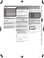
FCC Information (For US customers)
nNOTE ON USE / OBSERVATIONS RELATIVES A L’UTILISATION
1. COMPLIANCE INFORMATION
Product Name: AV Surround Receiver
Model Number: AVR-4810CI
This product contains FCC ID: PPQ-NM100BB.
This product complies with Part 15 of the FCC Rules. Operation is subject to the following two conditions: (1) this
product may not cause harmful interference, and (2) this product must accept any interference received, including
interference that may cause undesired operation.
Denon Electronics (USA), LLC
100 Corporate Drive, Mahwah, NJ 07430-2041
Tel. 201-762-6500 (Main)
• Do not let foreign objects into the unit.
• Ne pas laisser des objets étrangers dans
• Keep the unit free from moisture, water,
l’appareil.
and dust.
• Protéger l’appareil contre l’humidité, l’eau
et la poussière.
2. IMPORTANT NOTICE: DO NOT MODIFY THIS PRODUCT
This product, when installed as indicated in the instructions contained in this manual, meets FCC requirements.
Modification not expressly approved by DENON may void your authority, granted by the FCC, to use the product.
3. CAUTION
•To comply with FCC RF exposure compliance requirement, separation distance of at least 20 cm must be
maintained between the antenna of this product and all persons.
•This product and its antenna must not be co-located or operating in conjunction with any other antenna or
transmitter.
4. NOTE
This product has been tested and found to comply with the limits for a Class B digital device, pursuant to Part 15
of the FCC Rules. These limits are designed to provide reasonable protection against harmful interference in a
residential installation.
This product generates, uses and can radiate radio frequency energy and, if not installed and used in accordance
with the instructions, may cause harmful interference to radio communications. However, there is no guarantee
that interference will not occur in a particular installation. If this product does cause harmful interference to radio or
television reception, which can be determined by turning the product OFF and ON, the user is encouraged to try to
correct the interference by one or more of the following measures:
•Reorient or relocate the receiving antenna.
•Increase the separation between the equipment and receiver.
•Connect the product into an outlet on a circuit different from that to which the receiver is connected.
•Consult the local retailer authorized to distribute this type of product or an experienced radio/TV technician for
help.
• Avoid high temperatures.
Allow for sufficient heat dispersion when
installed in a rack.
• Eviter des températures élevées.
Tenir compte d’une dispersion de chaleur
suffisante lors de l’installation sur une
étagère.
• Do not let insecticides, benzene, and
thinner come in contact with the unit.
• Unplug the power cord when not using the • Ne pas mettre en contact des insecticides,
du benzène et un diluant avec l’appareil.
unit for long periods of time.
• Débrancher le cordon d’alimentation
lorsque l’appareil n’est pas utilisé pendant
de longues périodes.
IC Information (For Canadian customers)
1. PRODUCT
This product contains 4491A-NM100BB.
This product complies with RSS-210 of Industry Canada. Operation is subject to the following two conditions:
(1) this product may not cause harmful interference, and (2) this product must accept any interference received,
including interference that may cause undesired operation.
This Class B digital apparatus complies with Canadian ICES-003.
APPAREIL
Cet appareil contiens 4491A-NM100BB.
Cet appareil est conforme à la norme CNR-210 du Canada. L’utilisation de ce dispositif est autorisée seulement
aux deux conditions suivantes : (1) il ne doit pas produire de brouillage, et (2) l’utilisateur du dispositif doit être
prêt à accepter tout brouillage radioélectrique reçu, même si ce brouillage est susceptible de compromettre le
fonctionnement du dispositif.
Cet appareil numérique de la classe B est conforme à la norme NMB-003 du Canada.
• Handle the power cord carefully.
Hold the plug when unplugging the cord.
• Manipuler le cordon d’alimentation avec
précaution.
Tenir la prise lors du débranchement du
cordon.
* (For apparatuses with ventilation holes)
• Do not obstruct the ventilation holes.
• Ne pas obstruer les trous d’aération.
• Never disassemble or modify the unit in
any way.
• Ne jamais démonter ou modifier l’appareil
d’une manière ou d’une autre.
2. CAUTION
To reduce potential radio interference to other users, the antenna type and its gain should be so chosen that the
equivalent isotropically radiated power (e.i.r.p.) is not more than that permitted for successful communication.
ATTENTION
Afin de réduire le risque d’interférence aux autres utilisateurs, il faut choisir le type d’antenne et son gain de façon à
ce que la puissance isotrope rayonnée équivalente (p.i.r.e.) ne soit pas supérieure au niveau requis pour l’obtention
d’une communication satisfaisante.
II
1.AVR4810CIEU_007.indd
3
2009/08/04
12:06:15
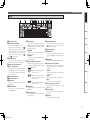
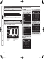
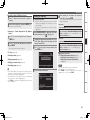
n Contents
Getting Started·······································································2
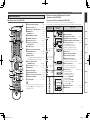
Playback····················································································66
Flow of Operations Through Playback·········································2
Cautions on Handling····································································2
Cautions on Installation································································2
Preparations···················································································3
Accessories···················································································3
About the Remote Control Unit·····················································3
Part Names and Functions····························································4
Front Panel·····················································································4
Display···························································································5
Rear Panel······················································································6
Remote Control Unit······································································7
Important Information·································································66
Playing Components····································································66
Playing a Blu-ray Disc Player/DVD Player·····································66
Playing an iPod® Using a Control Dock for iPod··························66
Playing an iPod® Connected Directly to the AVR-4810CI’s
USB Port······················································································68
Tuning in Radio Stations·····························································69
Listening to FM/AM Broadcasts··················································70
Listening to XM Satellite Radio····················································71
Listening to SIRIUS Satellite Radio··············································73
Listening to HD Radio Technology···············································75
Playing Network Audio, USB Memory Devices························76
Listening to Internet Radio··························································78
Playing Files Stored on a Computer·············································80
Playing Files Stored on USB Memory Devices····························81
Listening to Napster····································································82
Listening to Rhapsody·································································83
Operations During Playback·······················································85
Adjusting the Master Volume·······················································85
Turning Off the Sound Temporarily (Muting)································85
Listening with Headphones·························································85
To Stop·························································································85
Stopping Playback Temporarily·····················································85
Fast-forwarding or Fast-reversing················································85
To Cue to the Beginning of a Track···············································85
Playing Repeatedly······································································86
Selecting Tracks············································································86
Shuffling Playback········································································86
Playing in Random Order·····························································86
Searching Pages··········································································86
Searching by First Letter······························································86
Selecting the Surround Mode (Surround Mode)······················87
Adjusting the Sound and Picture Quality
(Audio/Video Adjust)···································································90
Adjusting the Sound (Audio Adjust)·············································90
Adjusting the Picture Quality (Picture Adjust)······························95
Connections··············································································9
Important Information···································································9
Cables Used for Connections························································9
Converting Input Video Signals for Output
(Video Conversion Function)························································ 10
Installing the Speakers································································11
Speaker Connections···································································14
Connecting Devices·····································································17
Connecting the Power Cord························································28
Once Connections are Completed··············································28
Turning the Power On··································································28
Turning the Power Off··································································28
Settings·····················································································29
GUI Menu Map·············································································29
GUI Menu Operation····································································30
Example of the Display of the GUI Mark at a Title·······················30
Examples of GUI Menu Screen Displays·····································30
Selecting the Input Source··························································31
Make the Optimal Speaker Settings, and Correct the Room
Acoustics (Audyssey™ Auto Setup)··········································32
Making Detailed Settings (Manual Setup)································39
Making the Input Settings (Source Select)·······························57
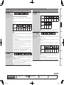
Checking the Status (Information)······························96
Other Operations and Convenient Functions········97
Other Operations·········································································97
Playing a Blu-ray Disc Player Compatible with
DENON LINK 4th·········································································97
Playing Super Audio CD·······························································98
Recording on an External Device (REC OUT mode)····················98
Convenient Functions··································································99
HDMI Control Function································································99
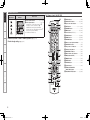
Setting the Power to Standby After a Certain Amount of Time
(Sleep Timer Function)······························································· 100
Adjust the Volume of the Speakers············································ 100
Saving Frequently Used Settings (Quick Select Function)········· 101
Playing the Same Network Audio on Different Devices
Connected in a Network (Party Mode Function)························ 101
Operating a Wireless LAN-Compatible Mobile Terminal to
Play Music and Still Pictures······················································ 102
Operating the AVR-4810CI with a Browser
(Web Control Function)······························································ 103
Various Memory Functions························································ 104
Playing in ZONE2/ZONE3/ZONE4 (Multi-zone
Function)· ···············································································105
Audio Output··············································································105
Video Output··············································································105
Playback······················································································106
Menu Operation·········································································107
Quick Select Function································································107
Sleep Timer Function·································································107
1.AVR4810CIEU_007.indd
5
2009/08/04
12:06:15
Getting Started
Operating the Connected Devices by Remote
Control Unit··········································································108
Connections
Settings
Playback
Multi-zone
Remote Control Information
Operating the Main Remote Control Unit ······························108
Operating AV Equipment ·························································· 108
Presetting·················································································· 109
Operating Preset Components ················································· 109
Setting the Remote ID ······························································ 112
Learning Function ····································································· 113
MACRO Function ······································································ 114
Punch Through Function ···························································· 114
Setting the Time the Backlight Stays Lit ··································· 115
Adjusting the Backlight’s Brightness········································· 115
Specifying the Zone Used with the Main Remote Control Unit
·································································································· 115
Resetting the Main Remote Control Unit ································· 116
Operating the Sub Remote Control Unit ································117
Switching Zones ······································································· 119
Switching the Multi-zone Input Source to the Same
Input Source as Used in the MAIN ZONE ································ 119
Setting the Zone for Which the Sub Remote Control Unit is
Used (ZONE SELECT LOCK Mode) ·········································· 119
Setting the Remote ID ······························································ 119
Resetting the Settings ······························································ 119
Other Information ·····························································120
Troubleshooting·································································130
Restoring All the Settings to as They were at the Time of
Purchase (Resetting the Microprocessor) ·······························134
Troubleshooting
Specifications ······································································135
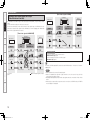
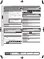
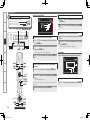
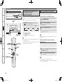
Getting Started
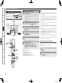
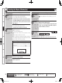
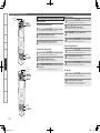
Flow of Operations Through
Playback
Perform the operations leading to playback on the AVR-4810CI in the
order shown below.
Connections
Installing/Setting the Speakers (vpage 11)
Speaker Connections (vpage 14)
Connecting Devices (vpage 17)
Turning the Power On (vpage 28)
Settings
Audyssey™ Auto Setup (vpage 32)
Manual Setup (vpage 39)
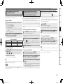
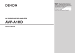
Cautions on Handling
• Before turning the power switch on
Check once again that all connections are correct and that there are
no problems with the connection cables.
• Power is supplied to some of the circuitry even when the unit is
set to the standby mode. When traveling or leaving home for long
periods of time, be sure to unplug the power cord from the power
outlet.
• About condensation
If there is a major difference in temperature between the inside of
the unit and the surroundings, condensation (dew) may form on
the operating parts inside the unit, causing the unit not to operate
properly.
If this happens, let the unit sit for an hour or two with the power
turned off and wait until there is little difference in temperature
before using the unit.
• Cautions on using mobile phones
Using a mobile phone near this unit may result in noise. If so, move
the mobile phone away from this unit when it is in use.
• Moving the unit
Turn off the power and unplug the power cord from the power
outlet.
Next, disconnect the connection cables to other system units before
moving the unit.
• Note that the illustrations in these instructions may differ from the
actual unit for explanation purposes.
b Perform “Manual Setup” as necessary.
Source Select (vpage 57)
List of preset codes ··································End of this manual
Cautions on Installation
Note:
For proper heat dispersal, do not install this unit in a confined
space, such as a bookcase or similar enclosure.
Specifications
Playback
b
Playing Components (vpage 66)
b
b Note
b
Wall
Selecting the Surround Mode (vpage 87)
Adjusting the Sound and Picture Quality
(vpage 90)
2
1.AVR4810CIEU_007.indd
6
2009/08/04
12:06:20
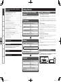
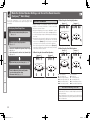
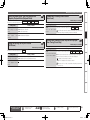
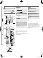
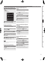
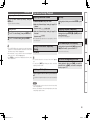
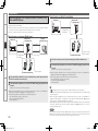
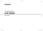
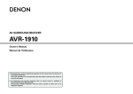
Accessories
Check that the following parts are supplied with the product.
i
(RC-1121)
Operating Range of the Remote Control Unit
Point the remote control unit at the remote sensor when operating it.
w Load the two batteries properly as indicated by the marks in the
battery compartment.
(RC-1126)
(RC-1121)
R03/AAA
LR6/AA
30°
Q1
Q2
or
Approx. 23 feet / 7 m
e Put the rear cover back on.
(RC-1126)
NOTE
Q4
Q5
Specifications
Q3
The set may function improperly or the remote control unit may not
operate if the remote control sensor is exposed to direct sunlight,
strong artificial light from an inverter type fluorescent lamp or infrared
light.
Troubleshooting
Q0
(RC-1121)
30°
Remote Control Information
y
(RC-1126)
Multi-zone
t
q Lift the clasp and remove the rear lid.
Playback
(DM-A409, Cord length: Approx. 25 ft / 7.6 m)........................ 1
Inserting the Batteries
Settings
qOwner’s manual....................................................................... 1
wGetting started......................................................................... 1
eWarranty (for North America model only)................................. 1
rService station list.................................................................... 1
tPower cord (Cord length: Approx. 6.2 ft / 1.9 m)..................... 1
yMain remote control unit (RC-1126).......................................... 1
uLR6/AA batteries (for RC-1126)................................................. 2
iSub remote control unit (RC-1121)........................................... 1
oR03/AAA batteries (for RC-1121).............................................. 2
Q0FM indoor antenna................................................................... 1
Q1AM loop antenna (small, for AM broadcasts)........................... 1
Q2AM loop antenna (large, for HD Radio broadcasts).................. 1
Q3Dipole antenna (for HD Radio broadcasts)............................... 1
Q4Rod antenna for wireless LAN connection............................... 1
Q5Setup microphone
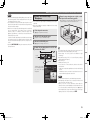
In addition to the AVR-4810CI, the included main remote control unit
(RC-1126) can also be used to operate the equipment listed below.
qDENON system components
wNon-DENON system components
• To operate component products other than DENON, you must set
the preset code (vpage 109 “Presetting”).
• If you are using a non-DENON AV device, or if you cannot operate
the device even after registering the preset code, memorize the
other device’s remote control signal in the AVR-4810CI remote
control unit (vpage 113 “Learning Function”).
• Insert the specified batteries in the remote control unit.
• Replace the batteries with new ones if the set does not operate
even when the remote control unit is operated close to the unit. (The
supplied batteries are only for verifying operation.)
• When inserting the batteries, be sure to do so in the proper direction,
following the “q” and “w” marks in the battery compartment.
• To prevent damage or leakage of battery fluid:
• Do not use a new battery together with an old one.
• Do not use two different types of batteries.
• Do not attempt to charge dry batteries.
• Do not short-circuit, disassemble, heat or dispose of batteries in
flames.
• If the battery fluid should leak, carefully wipe the fluid off the inside
of the battery compartment and insert new batteries.
• Remove the batteries from the remote control unit if it will not be in
use for long periods.
• Used batteries should be disposed of in accordance with the local
regulations regarding battery disposal.
Connections
Thank you for purchasing this DENON product. To ensure proper
operation, please read this owner’s manual carefully before using the
product.
After reading them, be sure to keep them for future reference.
NOTE
About the Remote Control Unit
Getting Started
Preparations
1.AVR4810CIEU_007.indd
7
2009/08/04
12:06:21
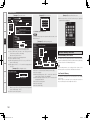
Getting Started
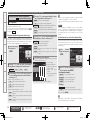
GWith the door openH
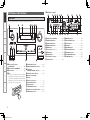
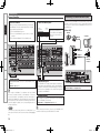
Part Names and Functions
E4
E5
E3
E2
E1 E0
W9
W8
W7
W6
Front Panel
For buttons not explained here, see the page indicated in parentheses ( ).
Connections
Q2
Q1
o i
Q0
u
y
Settings
Q7
Playback
Multi-zone
Q3 Q4 Q5
Remote Control Information
q
Q6
w e
qPower operation button
(ON/STANDBY)············································ (28)
Troubleshooting
wPower indicator (hON jOFF)·················· (28)
ePower switch··············································· (28)
rDoor
Specifications
When you are using buttons and/or terminals
behind the door, press the bottom of the door to
open it. When not using buttons and/or terminals
behind the door, close it. Be careful not to catch
your fingers when closing the door.
r
t
Q8
Q9
W0
W1
W2
Q7Headphones jack (PHONES)······················· (85)
Q8ZONE2 ON/OFF button····························· (106)
Q9ZONE3 ON/OFF button····························· (106)
W0ZONE4 ON/OFF button····························· (106)
W1MENU button··············································· (30)
W2Cursor buttons (uio p)··························· (30)
W3ENTER button·············································· (30)
W4RETURN button··········································· (30)
W5V.AUX INPUT connectors··························· (24)
W6SETUP MIC jack··········································· (33)
W3
W4
W5
W7HDMI IN connector······································ (17)
W8USB (iPod DIRECT) port······························ (24)
W9STATUS button··········································· (96)
E0DSX button·················································· (93)
E1RESTORER button······································· (94)
E2DIRECT/STEREO button······················· (88, 89)
E3PURE DIRECT button·································· (89)
E4DSP SIMULATION button··························· (88)
E5STANDARD button······································ (87)
tQUICK SELECT buttons·····························(101)
yMASTER VOLUME control knob················ (85)
uAUDYSSEY
DYNAMIC VOLUME™ indicator················· (92)
iAUDYSSEY DSX™ indicator······················ (93)
oMaster volume indicator
Q0Display
Q1Remote control sensor································· (3)
Q2SOURCE SELECT knob······························· (31)
Q3SOURCE button··········································· (31)
Q4TUNING PRESET button················· (70, 72, 75)
Q5ZONE 2/3/4 / REC SELECT button····· (98, 106)
Q6VIDEO SELECT button································ (60)
1.AVR4810CIEU_007.indd
8
2009/08/04
12:06:22
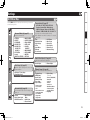
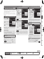
Display
W1
Q9 Q8Q7 Q6 Q5 Q4
W0
Q3
Q2
Q1
u y
r
t
Connections
Q0 o i
Getting Started
Part Names and Functions
Settings
w
eInformation display
The input source name, surround mode, setting
values and other information are displayed here.
rOutput signal channel indicators
tMonitor output indicators
yQUICK SELECT indicators
uMaster volume indicator
iMUTE indicator
This lights when the mute mode is selected
(vpage 85).
oRESTORER indicator
This lights when the RESTORER mode is
selected (vpage 94).
Q1AUDYSSEY MULTEQ XT indicators
Lighting is as follows, depending on the setting
of “Dynamic EQ” (vpage 92) and “Dynamic
Volume” (vpage 93).
•
: When “Dynamic EQ” and “Dynamic
Volume” are “ON”.
•
: When the “Dynamic EQ” setting is
“ON” and the “Dynamic Volume”
setting is “OFF”.
•
: When “Dynamic EQ” and “Dynamic
Volume” are “OFF”.
Q2SLEEP indicator
This lights when the sleep mode is selected
(vpage 100).
Q3Multi zone indicators
These light when the power for the respective
zone is turned on.
This lights when Advanced AL24 Processing
(vpage 122) or AL 24 Processing Plus
(vpage 122) is activated.
Q5Input mode indicators
Q6D.LINK indicator
This lights when playing using DENON LINK
connections (vpage 98 “Playing Super Audio
CD”).
Q7HDMI indicator
This lights when playing using HDMI connections.
Q8Tuner reception mode indicators
These light according to the reception conditions
when the input source is set to “TUNER” or
“HD Radio”.
•STEREO
In the FM mode, these light when receiving analog
stereo broadcasts.
•TUNED
Lights when the broadcast is properly tuned in.
•AUTO
These light when in the auto tuning mode.
Q9Recording output source indicator
Specifications
These indicators light during party mode
(vpage 101 “Playing the Same Network Audio
on Different Devices Connected in a Network
(Party Mode Function)”).
•ORGANIZER
This lights to indicate that party mode has
started as Organizer.
•ATTENDEE
This lights to indicate that party mode has
started as Attendee.
Troubleshooting
These light according to the HDMI monitor output
setting (vpage 43 “Monitor Out”). When set
to “Auto (Dual)”, the indicators light according to
the connection status.
Q4Advanced AL24 indicator
Remote Control Information
These light when digital signals are input.
When playing HD Audio sources, the“
”
indicator lights when an extension channel (a
channel other than the front, center, surround,
surround back or LFE channel) is input. If there
are two or more extension channels, the “
”
and “
” indicators light.
Q0PARTY indicators
Multi-zone
qInput signal indicators
wInput signal channel indicators
e
Playback
q
This lights when the REC OUT mode is selected
(vpage 98).
W0Decoder indicators
These light when the respective decoders are
operating.
W1HD indicator
This lights during HD Radio reception.
1.AVR4810CIEU_007.indd
9
2009/08/04
12:06:24
Getting Started
Part Names and Functions
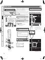
Rear Panel
W0 e
Q9
Q8
Q7
Q5
Q6 Q5
Q4
Q3 Q2 u
Q1
Q0
Connections
Settings
Playback
Multi-zone
W2
W3
W2
W1
Remote Control Information
Troubleshooting
q
w
e
rt y
Specifications
qRS-232C connector······································ (26)
wREMOTE CONTROL jacks··························· (26)
eAnalog audio connectors····················(18 ~ 21)
rTRIGGER OUT jacks···································· (26)
tDOCK CONTROL jack·································· (19)
ySIGNAL GND terminal································ (19)
uSpeaker terminals······························· (14 ~ 16)
iAC inlet························································· (28)
u
oAC OUTLETS················································ (28)
Q0HD Radio antenna terminals······················ (23)
Q1WLAN ANTENNA terminal························· (27)
Q2ETHERNET connector································· (26)
Q3USB (iPod DIRECT) port······························ (24)
Q4XM connector·············································· (21)
Q5Digital audio connectors·····················(18 ~ 24)
Q6DENON LINK connector······························ (23)
i
o
Q7COMPONENT VIDEO connectors········· (18, 20)
Q8HDMI connectors········································· (17)
Q9VIDEO / S-VIDEO connectors·············(18 ~ 21)
W0SIRIUS connector········································ (22)
W1FM/AM antenna terminals························· (22)
W2PRE OUT connectors··························· (25, 105)
W3EXT. IN connectors······································ (25)
1.AVR4810CIEU_007.indd
10
2009/08/04
12:06:26
nOperations Possible by Main Remote Control Unit
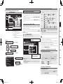
Remote Control Unit
Operations on the AVR-4810CI
Operations on devices other that the AVR-4810CI
Main Remote Control Unit (RC-1126)
q
w
Q1
Number buttons····························(70 ~ 75, 79)
oTV INPUT button········································(110)
Q0Remote control signal transmitter·············· (3)
Q1QUICK SELECT button······················· (101, 107)
E3
W4
W5
W6
W7
W2
W3
W8
W9
E3
MACRO button···········································(114)
Q2Function buttons
r
See “Operations Possible by Main Remote Control
Unit” (vpage 7, 8) for more information.
Q3Power operation buttons
Q4
Q4Cursor buttons (uio p)·························· (30)
Q5ENTER button·············································· (30)
Q6Return button (RTN)··································· (30)
Q7SOURCE SELECT button···························· (31)
Q8Master volume control buttons (VOL)······ (85)
Q9Muting button (MUTE)······························· (85)
W0RC SETUP button······································ (109)
(POWER ON / OFF)······························ (28, 106)
Q5
Q6
t
Q7
y
u
Q8
Q9
o
W7PARTY button··················································(101)
W8Monitor select button (M.SEL)······················· (43)
W9Video select button (V.SEL)···························· (60)
E0Multi-zone power buttons····························· (106)
•Muiti-zone power on button (ON)
•Muiti-zone power off button (OFF)
E1Device power buttons···························· (109, 110)
•Device power on button (ON)
E0
•Device power off button (OFF)
E2System buttons·······························(85, 109 ~ 111)
•Repeat button (RPT)
E4
•Random button (RND)
•Disc skip up button (Skip+)
•Skip button (8, 9)
•Play button (1)
•Search button (6, 7)
•Still / Pause button (3)
E2
•Stop button (2)
E0 E3QUICK SELECT button···························· (101, 107)
E4MACRO button················································(114)
E1
E0
W0
Specifications
The time for which the backlight stays on can
be changed (vpage 115 “Setting the Time the
Backlight Stays Lit”).
i
W3
•STANDARD button (STD)
•PURE DIRECT button (PURE)
•DIRECT / STEREO button (D/ST)
•DSP SIMULATION button (SIMU)
Troubleshooting
Q3
W1MULTEQ® XT button (MULTEQ)···················· (92)
W2DSX button (SPKR)·········································· (93)
W3Sleep timer button (SLEEP)···················(100, 107)
W4DYNAMIC EQ™ button (DYN EQ)··················· (92)
W5DYNAMIC VOLUME™ button (DYN VOL)······ (93)
W6Surround mode buttons···························· (88, 89)
Remote Control Information
W1
Button name
Multi-zone
Q2
SEARCH button··········································· (86)
tRESTORER button (RSTR)·························· (94)
yCHANNEL LEVEL button·························· (100)
uChannel buttons (CH)··························(70 ~ 75)
iInput source select buttons························ (31)
Function button
indicator
Playback
e
Selected Device
select button
Settings
• Preset the remote control codes of the devices to be operated (vpage 109).
• The function button indicator changes depending on the Device select button you have selected.
Connections
Q0
qSignal transmission indicator·················· (108)
wDevice select buttons································ (108)
eZone indicators / MACRO indicator········· (108)
rMENU button··············································· (30)
Getting Started
Part Names and Functions
1.AVR4810CIEU_007.indd
11
2009/08/04
12:06:28
Getting Started
Part Names and Functions
Selected Device
select button
Function button
indicator
Button name
Sub Remote Control Unit (RC-1121)
Q1
Connections
E5 Preset Channel buttons ····················(70 ~ 75, 79)
E6 Tuner system buttons ····························(70 ~ 75)
E5
E6
Settings
• Tuning down / Channel down button (TU f)
• Tuning up / Channel up button (TU d)
• FM/AM band switching button (BAND)z
• Tuning mode (Auto / Manual) button (MODE)z
• Preset memory button (MEMO)
z : TUNER and HD Radio only
q
Q2
Q3
Q4
w
Playback
n Multi-zone (ZONE2 / ZONE3 / ZONE4) operations (vpage 105)
n Punch through setting (vpage 116)
e
Multi-zone
Q5
Remote Control Information
r
t
Q6
Q7
y
Q8
Q9
u
Troubleshooting
i
q ZONE indicators ········································(119)
w QUICK SELECT buttons ···················· (101, 107)
e Input source select buttons······················(117)
r SHIFT button······························· (70 ~ 75, 117)
t CHANNEL button ······································(117)
y MENU button······································(107, 117)
u Cursor buttons (uio p) ························(117)
i SEARCH button ···································(86, 118)
o REPEAT button ····································(86, 118)
Q0 RANDOM button ··································(86, 118
Q1 Remote control signal transmitter ············· (3)
Q2 ZONE SELECT button ·······························(119)
Q3 Zone power on/off buttons ····················· (106)
Q4 Advanced setup button ····························(119)
Q5 MAIN ZONE call button ····························(119)
Q6 Master volume control buttons ·············· (106)
Q7 Muting button (MUTE) ···························· (106)
Q8 MEMORY button ·······································(117)
Q9 ENTER button ············································(117)
W0 RETURN button ·········································(117)
W1 System buttons ·········································(117)
W2 ALL MUSIC/FAVORITES
(DIRECT PLAY) button ······························(117)
W0
W3 USB (DIRECT PLAY) button ················(81, 118)
W1
o
Specifications
Q0
W2
W3
8
1.AVR4810CIEU_007.indd
12
2009/08/04
12:06:29
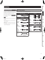
Important Information
Cables Used for Connections
Select the cables (sold separately) according to the equipment being connected.
Video cables
Audio and video cables
HDMI connections
Audio cables
(Red)
Component video cable
(Orange)
S-Video
connections
Coaxial digital cable
Optical cable
L
L
R
R
S-Video cable
(Yellow)
Video cable
Other cables
Audio cable
DENON LINK
connections
Audio cable
Network
connections
(wired LAN)
Remote Control Information
Analog
(White)
connections
(Red)
(stereo, surround)
Video
connections
Multi-zone
Optical digital
connections
Analog
connections
(monaural, for
subwoofer)
(Blue)
Playback
Coaxial digital
connections
(Green)
Settings
Component
video
connections
HDMI cable
NOTE
•Do not plug in the power cord until all connections have been
completed.
•When making connections, also refer to the operating instructions of
the other components.
•Be sure to connect the left and right channels properly (left with left,
right with right).
•Do not bundle power cords together with connection cables. Doing
so can result in humming or noise.
Connections
Connections for all compatible audio and video signal formats
are described in this owner’s manual. Please select the types of
connections suited for the equipment you are connecting.
After connections are completed, certain settings must be made on
the receiver. Make the settings indicated “ Set as Necessary ”
for the individual items.
Getting Started
Connections
DENON LINK cable
Ethernet cable
Speaker
connections
Speaker cables
Troubleshooting
Specifications
1.AVR4810CIEU_007.indd
13
2009/08/04
12:06:30
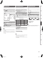
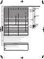
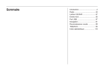
GFlow of video signals for ZONE2H
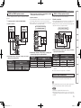
Converting Input Video Signals for Output
(Video Conversion Function)
AVR-4810CI
Connections
The AVR-4810CI has 4 different types of video input/output terminal (HDMI, Component video, S-Video,
Video).
Use the terminals according to the devices to be connected.
This function automatically converts various formats of video signals input to the AVR-4810CI into the
format used to output the video signals from the AVR-4810CI to a monitor. (vpage 129 “Relationship
Between Video Signals and Monitor Output”).
Settings
Getting Started
Important Information
GFlow of video signals for MAIN ZONEH
AVR-4810CI
Monitor
Playback
Video device
Multi-zone
Remote Control Information
Output
Input
(IN)
HDMI connector
HDMI connector
Output
(MONITOR OUT)
HDMI connector
HDMI connector
Component video
connectors
Component video
connectors
S-Video connector
S-Video connector
S-Video connector
S-Video connector
Video connector
Video connector
Video connector
Video connector
Troubleshooting
Surround back
speaker
Component video
connectors
Input
Component video
connectors
: When 480i/576i signals are input
Monitor
Video device
Output
Input
(IN)
Component video
connectors
Component video
connectors
S-Video connector
S-Video connector
Video connector
Video connector
Output
(MONITOR OUT)
Component video
connectors
Video connector
Input
Component video
connectors
Video connector
Set as Necessary
• Set when not using the video conversion function.
“Video Convert” (vpage 60)
• Set when changing the resolution of the video signal.
“Resolution” (vpage 61)
Resolutions of HDMI-compatible TVs can be checked at “HDMI Information” – “Monitor1” or “Monitor2”
(vpage 96).
NOTE
Specifications
• HDMI signals cannot be converted into analog signals.
• When a non-standard video signal from a game machine or some other source is input, the video
conversion function might not operate.
• 480p/576p/1080i/720p/1080p component video input signals cannot be converted into S-Video or Video
format.
• When using the component video output connectors for connection to the ZONE2 monitor, the ZONE2’s
on-screen display is not displayed.
10
1.AVR4810CIEU_007.indd
14
2009/08/04
12:06:31
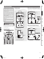
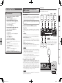
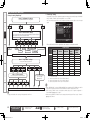
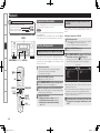
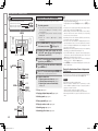
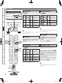
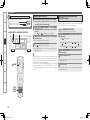
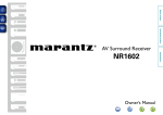
n Installing the speakers
The illustration below shows the recommended speaker layout.
Front speakers
Front wide speakers
Front speakers
Center speaker
Subwoofer
z1
z
2
z
5
Surround speakers
z4 z
z1:22 ~ 30˚
z2:90˚ ~ 110˚
Surround
Surround back
speaker
speaker
Front
speaker
2 to 3 feet /
60 to 90 cm Point slightly
downwards
GAs seen from aboveH
n When no surround back speaker is being used
Surround back
speakers
Use the layout shown in the illustration below for the surround speaker.
GAs seen from aboveH
Front height Point slightly
downwards
speaker
GAs seen from the sideH
Front speakers
Center speaker
Monitor
Surround
speaker
Point slightly
downwards
z1:22 ~ 30˚
z2:120˚
Subwoofer
Front wide 2 to 3 feet /
speaker 60 to 90 cm
Surround back
speaker
Front speaker
Center speaker
GAs seen from the sideH
b1 : Recommendation for Dolby Pro Logic gz
b2 : Recommendation for Audussey DSX
Surround back speakers
Surround
speaker
2 to 3 feet /
60 to 90 cm
Surround speakers
GAs seen from aboveH
GAs seen from the sideH
Specifications
Surround
speaker
Front
speaker
6
At least
1 m z1
Troubleshooting
Subwoofer
Front wide
speakers
z
Front wide
speakers
z2
z1
Front speakers
Remote Control Information
Below we introduce examples of speaker layouts. Refer to
these to arrange your speakers according to their type and
how you want to use them.
Multi-zone
Surround back
speaker
Playback
Monitor
3 Subwoofer
z
2
z
1
Center speaker
Monitor
Settings
z1:22 ~ 30˚
z2:22 ~ 45˚
z3:55 ~ 60˚
z4:90 ~ 110˚
z5:135 ~ 150˚
z6:45˚ (b2)
Surround
speakers
Front height speakers
Use the layout shown in the illustration below for the surround back
speaker.
Front height speakers
a Speaker Layout
Installing All the Speakers
n When only one surround back speaker is being used
Connections
The AVR-4810CI supports up to 11.1-channel surround
sound playback by adding front height and front wide
channels to the 7.1-channel (Front/Center/Surround/
Surround Back/Subwoofer).
Installing front height and front wide speakers offers
an even wider and deeper sensation compared with
traditional surround spacing thanks to the advanced
simulation surround technology Audyssey DSX and
Dolby Pro Logic gz decoder.
To use Audyssey DSX, install front wide or front height
speakers. (Refer to page 121 for more information on
Audyssey DSX)
To use Dolby Pro Logic gz, install front height speakers.
(Refer to page 120 for more information on Dolby Pro
Logic gz)
Getting Started
Installing the Speakers
Surround
speaker
11
1.AVR4810CIEU_007.indd
15
2009/08/04
12:06:32
Getting Started
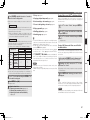
Installing the Speakers
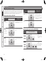
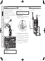
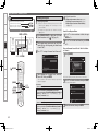
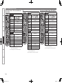
s Example Installation of Speakers
Connections
The AVR-4810CI supports a wide variation of surround playback such as in the example speaker installations
shown below (11.1/9.1/7.1/6.1/5.1ch). It is also possible to have speaker output in rooms other than the
room (MAIN ZONE) where the surround is playing (multi-zone playback), or to enjoy the high quality sound
of the MAIN ZONE front speakers (using bi-wiring/bi-amping). Set “Amp Assign” as appropriate for the
speaker system being used. See page 14 for more information on speaker connections.
Example of Speaker Installation in MAIN ZONE
Speaker system
•Set “Configuration” to “7.1ch”.
•Set “Extra Channel” to “SB”.
MAIN ZONE
6.1ch
• 5.1ch+SB (1 speaker)
Settings
bConnect the surround back speaker to
Lch on the S.BACK terminal.
bIn the GUI menu, set “Speaker
Configuration” – “Surround Back” to
“1spkr” (vpage 41).
(SB : Surrond Back / FH : Front Height / FW : Front wide)
Speaker system
Example of speaker installation
Playback
MAIN ZONE
11.1ch
Multi-zone
Remote Control Information
MAIN ZONE
• 5.1ch+SB+FH
or
• 5.1ch+SB+FW
or
• 5.1ch+FH+FW
•Set “Configuration” to “9.1ch”.
•Set “Extra Channel (SB/FH/FW)” to be
used.
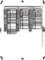
When using speaker terminals for multi-zone (ZONE2/ZONE3)
Multi-zone
speaker
system
Troubleshooting
Specifications
• 5.1ch+SB
or
• 5.1ch+FH
or
• 5.1ch+FW
MAIN ZONE
•Set “Assign Mode” to
“+Z2”.
ZONE2
bConnect speakers to
the ZONE2 speaker
terminals.
MAIN ZONE
•Set “Configuration” to “7.1ch”.
•Set “Extra Channel (SB/FH/FW)” to be
used.
+
ZONE2
MAIN ZONE
+
(Example of 5.1ch+SB installation)
“Amp Assign” setting
(vpage 39 ~ 41)
Example of speaker installation
(Example of 5.1ch+SB+FH
installation)
MAIN ZONE
7.1ch
•Set “Configuration” to “5.1ch”.
MAIN ZONE
5.1ch
bUse the PRE OUT terminal for the front
wide channel output.
• 5.1ch+SB+FH+FW
9.1ch
“Amp Assign” setting
(vpage 39 ~ 41)
•Set “Configuration” to “11.1ch”.
“Amp Assign” setting
(vpage 39 ~ 41)
Example of speaker installation
ZONE2
+
MAIN ZONE
ZONE2
ZONE3
•Set “Assign Mode” to
“+Z2+Z3”.
bConnect speakers to
the ZONE2 and ZONE3
speaker terminals.
ZONE3
(Default)
12
1.AVR4810CIEU_007.indd
16
2009/08/04
12:06:33
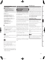
When using front speakers with bi-wiring or bi-amping
Example of speaker installation
“Amp Assign” setting
(vpage 39 ~ 41)
Connections
• When bi-wiring :
Set “Front” to “Bi-WIRING”.
MAIN ZONE
• When bi-amp :
Set “Front” to “Bi-AMP.
Settings
Playback
b Bi-wire or bi-amp the front speakers to
the front speaker terminals and Bi-Wir./BiAmp speaker terminals. See page 15 on
how to connect.
MAIN ZONE
“Amp Assign” setting
(vpage 39 ~ 41)
• When bi-wiring :
Set “Front” to “2CH BW”.
Remote Control Information
MAIN ZONE
Multi-zone
When using different front speakers for dedicated 2-channel DIRECT/STEREO
mode playback
Example of speaker installation
• When bi-amp :
Set “Front” to “2CH BA”.
b Bi-wire or bi-amp the speakers used for
dedicated 2-channel playback to the
ZONE2 and ZONE3 speaker terminals.
Switching
Multi channel surround
Getting Started
Installing the speakers
DIRECT/STEREO
Troubleshooting
Specifications
1.AVR4810CIEU_007.indd
17
2009/08/04
12:06:34
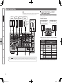
Getting Started
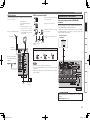
Speaker Connections
The AVR-4810CI can be connected to a maximum of three subwoofers.
The same signal is output from each subwoofer terminal.
Connections
Front
speakers
Center
speaker
Surround
speakers
Subwoofer
(1st unit)
Settings
Playback
w
(L)
(R)
q w
q
w
q
w
Subwoofer
with built-in
amplifier
(R)
qw
q
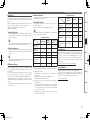
Use when connecting surround back speakers, front height speakers
or front wide spekars.
n Speaker connections
(2nd unit) (3rd unit)
(L)
A : S.BACK/F.HEIGHT/F.WIDE and F.HEIGHT/
F.WIDE speaker terminals
*/
*/
Surround back speakers,
Front height speakers
or Front wide speakers
Front height speakers or
Front wide speakers
*/
(L)
Multi-zone
w
(R)
qw
(L)
q
w
(R)
qw
q
Remote Control Information
n Relationship between “Amp Assign” settings and channels
output by each speaker terminal
“Amp Assign”
setting
(vpage 39 ~ 41)
Config.
Troubleshooting
11.1ch
(b)
9.1ch
C
A
B
Specifications
For the A B C speaker terminals, the output channels are different depending on the “Amp Assign” setting. Set
“Amp Assign” to suit the speaker system being used and connect the speakers referring to the following chart.
7.1ch
5.1ch
Channels output by each speaker
terminal
Extra
Channel
S.BACK/
F.HEIGHT/
F.WIDE
F.HEIGHT/
F.WIDE
SB/FH/FW
S.BACK
F.HEIGHT
SB/FW
SB/FH
FH/FW
SB
FH
FW
–
S.BACK
S.BACK
F.HEIGHT
S.BACK
F.HEIGHT
F.WIDE
–
F.WIDE
F.HEIGHT
F.WIDE
–
–
–
–
b:U
se the PRE OUT terminal for the front wide channel output.
14
1.AVR4810CIEU_007.indd
18
2009/08/04
12:06:37
w When front speakers for dedicated 2-channel DIRECT/STEREO
B : ZONE2 and ZONE3 speaker terminals
Use when installing multi-zone speakers or dedicated 2-channel
speakers.
n Speaker connections
w
(R)
q w
(L)
q
w
Front speaker (For Bi-Amp)
q w
q
HIGH
w (R) q
LOW
LOW
q
w
Channels output by each speaker
terminal
q
LOW
w
q
q
Channels output by each speaker
terminal
ZONE2
FRONT (2ch BW)
FRONT (2ch BA)
LOW
w
ZONE3
FRONT (2ch BW)
FRONT (2ch BA)
b Can be selected when “Assign Mode” is “NORMAL”.
n Relationship between “Amp Assign” settings and channels
output by each speaker terminal
“Amp Assign”
setting
(vpage 39 ~ 41)
“Front”
Bi-Wiring b1
Bi-Amp
b2
Channels output by each speaker
terminal
Bi-Wir. or
Bi-Amp
FRONT (BW)
FRONT (BA)
FRONT
FRONT (BW)
FRONT (BA)
b1 Can be selected when “Assign Mode” is “NORMAL”, “+Z2” or
“+Z2+Z3”.
b2 Can be selected when “Assign Mode” is “NORMAL”.
These connections make for higher quality playback sound with no
interference between the signals of the bass and treble units.
Specifications
About Bi-amp Connections
Troubleshooting
ZONE3
–
ZONE3
“Amp Assign”
setting
(vpage 39 ~ 41)
“Front”
2CH BW b
2CH BA b
HIGH
w (R) q
Remote Control Information
n Relationship between “Amp Assign” settings and channels
output by each speaker terminal
HIGH
w (L) q
Multi-zone
HIGH
w (L) q
n Relationship between “Amp Assign” settings and
channels output by each speaker terminal
ZONE2
ZONE2
ZONE2
• You can make Bi-amp or Bi-wire connections to one speaker system
which supports Bi-amp or Bi-wire connection as shown below.
• Bi-amp or Bi-wire can only be used with speakers that support Biamp or Bi-wire. Refer to your speaker manual.
(R)
w
“Amp Assign”
setting
(vpage 39 ~ 41)
Assign Mode
+Z2
+Z2+Z3
n Speaker connections
Playback
(L)
Front speaker (For Bi-Amp)
for 2CH DIRECT/STEREO
ZONE3
speakers
Use when front speakers are bi-wired or bi-amped.
Settings
ZONE2
speakers
n Speaker connections
• You can make Bi-amp or Bi-wire connections to one speaker system
which supports Bi-amp or Bi-wire connection as shown below.
• Bi-amp or Bi-wire can only be used with speakers that support Biamp or Bi-wire. Refer to your speaker manual.
C : Bi-Wir. or Bi-Amp speaker terminals
Connections
q Connecting speakers for multi-zone (ZONE2/ZONE3)
mode playback are bi-wired or bi-amped
Getting Started
Speaker Connections
When making a bi-amp connection, the same signal is output from the
front speaker terminal and the “Bi-Wir. or Bi-Amp“ terminal.
NOTE
• Use speakers compatible with bi-amp connections.
• When making bi-amp connections, be sure to remove the shortcircuiting plate or wire between the speaker’s woofer and tweeter
terminals.
15
1.AVR4810CIEU_007.indd
19
2009/08/04
12:06:39
Getting Started
Speaker Connections
n When using a banana plug
When the “Assign Mode” is set to “ALL Z2” or “ALL Z3”, only multi-zone audio is output from the AVR-4810CI speaker terminals.
For output in the MAIN ZONE, connect the output from the AVR-4810CI pre-out terminal to the power amp in the other room.
Connections
Use speakers where one speaker has an impedance of 6 ~ 16 Ω/
ohms. When using a speaker with impedance of 6 Ω/ohms to 8 Ω/
ohms, make sure to set the “Speaker Impedance” in the GUI menu
to “6 Ω/ohms”.
."*/;0/&
Settings
'-
'3
NOTE
$
• Connect so that the speaker cable core wires do not protrude from
the speaker terminal. The protection circuit may be activated if the
core wires touch the rear panel or if the + and – sides touch each
other (v“Protection Circuit”).
• Never touch the speaker terminals while the power supply is
connected. Doing so could result in electric shock.
AVR-4810CI
Playback
Multi-zone
4-
Power amplifier
Protection Circuit
43
Remote Control Information
;0/&;0/&
-
3
-
3
Troubleshooting
Connecting the Speaker Cables
Carefully check the left (L) and right (R) channels and + (red) and – (black) polarities on the speakers being connected to the AVR-4810CI, and
be sure to interconnect the channels and polarities correctly.
Specifications
off about 0.03 ft/10 mm of sheathing
1 Peel
from the tip of the speaker cable, then
either twist the core wire tightly or
terminate it.
the
speaker
2 Turn
counterclockwise to loosen it.
Tighten the speaker terminal firmly before
inserting the banana plug.
the speaker terminal clockwise to
4 Turn
tighten it.
If the core wires touch the rear panel and the screws etc., or the ±
sides touch each other, the protection circuit will be activated and the
power indicator will flash red at intervals of 0.5 secs.
If the protection circuit is activated, the speaker output is isolated, and
the power supply goes to the standby state. If the power supply is
turned off, after the power supply cord is withdrawn, please confirm
that speaker cable and input cable are connected.
Also, if replaying large sound levels by using a speaker having an
impedance less than that specified (eg, 4 Ω/ohms), the temperature
will rise, and the protection circuit might be activated. The power
supply will go into the standby state, and the power indicator will flash
red at 2 second intervals.
In this case, please switch off the power supply, and wait until the
AVR-4810CI has cooled down, and the surrounding ventilation is
good.
Even if there are no problems with the surrounding ventilation and
connections, in the event of the protection circuit becoming activated,
due to thinking that the AVR-4810CI has failed, please contact DENON
Service center after switching off.
terminal
the speaker cable’s core wire to
3 Insert
the hilt into the speaker terminal.
16
1.AVR4810CIEU_007.indd
20
2009/08/04
12:06:41
Connecting Devices
• Digital Video Recorder (vpage 20)
• Video Cassette Recorder (vpage 20)
n Connections to Other Devices
n Connecting to a Home network (LAN) (vpage 26)
Video
cassette
recorder
Digital
video
recorder
)%.*
065
)%.*
065
)%.*
065
)%.*
065
)%.*
065
“HDMI”, “HDMI logo” and “High-Definition Multimedia
Interface” are trademarks or registered trademarks of HDMI
Licensing LLC.
n Functions Usable with HDMI Connections
Deep Color
Eliminates on-screen color banding, for smooth tonal transitions
and subtle gradations between colors. Enables increased contrast
ratio.
x.v.Color
Lets HDTVs display colors more accurately. Enables displays with
natural, vivid colors. “x.v.Color” is a Sony registered trademark.
[Rear Panel]
Auto Lip Sync (vpage 43)
NOTE
If you connect the receiver to a TV that supports the Auto Lip Sync
function, it can automatically correct delay between the audio and
video.
HDMI Control Function (vpage 99)
This function allows you to operate external devices from the
receiver and operate the receiver from external devices.
NOTE
)%.*
*/
Monitor
1
Monitor
2
Game
console
)%.*
065
n Copyright Protection System (HDCP)
To play DVD-Video and DVD-Audio digital video and audio via the
HDMI/DVI connection, the connected Blu-ray disc player, DVD
player and monitor each need to support a copyright protection
system called HDCP (High-bandwidth Digital Content Protection).
HDCP is copyright protection technology comprised of data
encryption and authentication of the connected AV device. The AVR4810CI supports HDCP. Please consult the operating instructions
of your Blu-ray disc player, DVD player or monitor.
[Front Panel]
Specifications
• These functions will not work if the device connected to the
HDMI terminal does not support Deep Color or x.v.Color signal
transfer or the Auto Lip Sync function.
• The HDMI control function may not work depending on the
device it is connected to and its settings.
• You cannot operate a TV or Blu-ray Disc player / DVD player that
is not compatible with the HDMI control function.
)%.*
*/
Depending on the monitor you have
connected, the display may not be
correct when you set to “Auto (Dual)”.
In such a case, set to either “Monitor 1”
or “Monitor 2” (vpage 43).
Troubleshooting
• Components Equipped with a DENON LINK connector
(vpage 23)
• Video Camera / Game Console (vpage 24)
• USB Port (vpage 24)
• Component with Multi-channel Output connectors
(vpage 25)
• External Power Amplifier (vpage 25)
• External Controller (vpage 26)
Satellite
receiver
Remote Control Information
• TV (vpage 21)
• Satellite Receiver / Cable Tuner (vpage 21)
• XM (vpage 21)
• SIRIUS (vpage 22)
• FM/AM (vpage 22)
• HD Radio Receiver (vpage 23)
HD player
Multi-zone
n Connect the Tuner
“HDMI” is the abbreviation of “High Definition Multimedia
Interface”. This interface allows transfer of digital video signals and
digital audio signals over a single HDMI cable.
DVD
player
Playback
n Connecting the Recording Components
n About HDMI
The AVR-4810CI allows connection of inputs from up to 6 HDMI
devices and output to 2 monitors.
Settings
• Blu-ray Disc Player / DVD Player (vpage 18)
• Control dock for iPod (vpage 19)
• CD Player (vpage 19)
• Record Player (vpage 19)
Important Information
Connections
Connections
n Connecting Devices Equipped with HDMI
Terminals (vpage 17)
n Connecting the Monitor (vpage 18)
n Connecting the Playback Components
Connecting Devices Equipped with
HDMI Terminals
Getting Started
Connecting Devices
NOTE
When a device that does not support HDCP is connected, video
signals are not properly output.
1.AVR4810CIEU_007.indd
21
2009/08/04
12:06:47
Getting Started
Connecting Devices
n HDMI Setup (vpage 43)
Connections
Settings
• Use a cable on which the HDMI logo is indicated (a certified HDMI
product) for connection to the HDMI connector. Normal playback
may not be possible when using a cable other than one on which the
HDMI logo is indicated (a non-HDMI-certified product).
• When the AVR-4810CI is connected to other devices with HDMI
cables, also connect the AVR-4810CI and TV using an HDMI cable.
• When connecting a device that supports Deep Color transmission,
please use a cable that is compatible with Deep Color.
• Video signals are not output if the input video signals do not match
the monitor’s resolution. In this case, switch the Blu-ray Disc/
DVD player’s resolution to a resolution with which the monitor is
compatible.
Playback
NOTE
Multi-zone
Remote Control Information
• If the GUI menu “HDMI Audio Out” setting (vpage 43) is set to
“Amp”, the sound may be interrupted when the monitor’s power is
turned off.
• The audio signal from the HDMI output terminal (sampling
frequency, number of channels, etc.) may be limited by the HDMI
audio specifications of the connected device regarding permissible
inputs.
n Connecting to a Device Equipped with a DVI-D
Terminal
Make settings for HDMI video/audio output.
• HDMI Audio Out
• RGB Range
• Monitor Out
• Vertical Stretch
• HDMI Control
• Auto Lip Sync
NOTE
The audio signals output from the HDMI connectors are only the
HDMI input signals.
Connecting the Playback Components
Blu-ray Disc Player / DVD Player
Select the terminal to use and connect the device.
For instructions on HDMI connections, see “Connecting Devices
Equipped with HDMI Terminals” on page 17.
Blu-ray Disc player / DVD player
Connecting the Monitor
• Select the terminal to use and connect the device.
• For video connections, see “Converting Input Video Signals for
Output (Video Conversion Function)” (vpage 10).
7*%&0
7*%&0
065
47*%&0
065
"6%*0
$0.10/&/57*%&0
065
:
1# 13
For instructions on HDMI connections, see “Connecting Devices
Equipped with HDMI Terminals” on page 17.
Monitor
"6%*0
065
3
L
R
L
R
$0"9*"065
7*%&0
47*%&0
*/
7*%&0
*/
$0.10/&/57*%&0
*/
:
1# 1 3
When an HDMI/DVI conversion cable (sold separately) is used,
the HDMI video signals are converted to DVI signals, allowing
connection to a device equipped with a DVI-D terminal.
NOTE
Troubleshooting
• No sound is output when connected to a device equipped with a
DVI-D terminal. Also make the audio connections.
• Signals cannot be output to DVI-D devices that do not support
HDCP.
• Depending on the combination of devices, the video signals may not
be output.
Set as Necessary
Specifications
Set this to change the input signal to which the input source is
assigned.
“Input Assign” (vpage 58)
Settings Related to HDMI Connections
Set as necessary. For details, see the respective reference pages.
n Input Assign (vpage 58)
NOTE
Set this to change the HDMI input terminal to which the input
source is assigned.
In the case of HD audio (Dolby TrueHD, DTS-HD and Dolby Digital Plus
and DTS Express) audio playback, connect with HDMI (vpage 17,
“Connecting Devices Equipped with HDMI Terminals”).
To listen to TV audio through this device, use the optical digital or
analog connection.
18
1.AVR4810CIEU_007.indd
22
2009/08/04
12:06:50
Control Dock for iPod
CD Player
Use a DENON control dock for iPod (ASD-1R or ASD-11R, sold
separately) to connect the iPod to the AVR-4810CI. For instructions on
the control dock for iPod settings, refer to the control dock for iPod’s
operating instructions.
Select the terminal to use and connect the device.
Turntable
(MM cartridge)
CD player
Connections
Control dock for iPod
Record Player
"6%*0
"6%*0
065
3
$0"9*"065
R
"4%3
"6%*0
065
(/%
L
R
L
R
R
Multi-zone
R
Playback
L
L
Settings
L
Getting Started
Connecting Devices
Remote Control Information
• With the default settings, the iPod can be used connected to the
VCR (iPod) connector.
• You can also connect the iPod you are using directly to the USB port
of the AVR-4810CI (vpage 24 “USB Port”).
NOTE
Specifications
Set as Necessary
Set other than when iPod is assigned to the VCR (iPod) terminal.
“Input Assign” – “iPod dock“ (vpage 60)
• The AVR-4810CI is compatible with record players with an MM
cartridge. When you connect to a record player with an MC
cartridge, use a commercially available MC head amp or a step-up
transformer.
• When you increase the volume without connecting the record player,
there may be “booming” noise from the speakers.
Troubleshooting
Set as Necessary
Set this to change the input signal to which the input source is
assigned.
“Input Assign” (vpage 58)
The SIGNAL GND terminal of the AVR-4810CI is not a safety ground
connection. Connect it to reduce noise when noise is excessive.
Note that depending on the record player, connecting the ground line
may have the reverse effect of increasing noise. In this case, it is not
necessary to connect the ground line.
19
1.AVR4810CIEU_007.indd
23
2009/08/04
12:06:54
Getting Started
Connecting Devices
Video Cassette Recorder
Connecting the Recording Components
Connections
• Select the terminal to use and connect the device.
• When recording analog audio, use the analog connection.
• See page 98 “Recording on an External Device (REC OUT mode)”
for operating instructions.
Digital Video Recorder
• Select the terminal to use and connect the device.
• When recording analog audio, use the analog connection.
• See page 80 “Recording on an External Device (REC OUT mode)” for operating instructions.
For instructions on HDMI connections, see “Connecting Devices
Equipped with HDMI Terminals” on page 17.
For instructions on HDMI connections, see “Connecting Devices Equipped with HDMI Terminals” on page 17.
Settings
Video cassette recorder
Digital video recorder
"6%*0
Playback
015*$"065
"6%*0
7*%&0
"6%*0
065
3
7*%&0
065
47*%&0
065
7*%&0
$0.10/&/57*%&0
065
:
1# 13
7*%&0
*/
47*%&0
*/
"6%*0
"6%*0
*/
3
Multi-zone
Remote Control Information
L
R
L
R
L
R
L
R
015*$"*/
"6%*0
065
3
7*%&0
7*%&0
065
47*%&0
065
7*%&0
7*%&0
*/
47*%&0
*/
"6%*0
"6%*0
*/
3
L
R
L
R
L
R
L
R
Troubleshooting
Specifications
Set as Necessary
Set as Necessary
Set this to change the input signal to which the input source is
assigned.
“Input Assign” (vpage 58)
NOTE
To record video signals through the AVR-4810CI, use the same type
of video cable for connection between the AVR-4810CI and the player
as the cable used for connection between the AVR-4810CI and the
recorder.
20
1.AVR4810CIEU_007.indd
24
2009/08/04
12:06:58
Connect the Tuner
TV
For instructions on HDMI connections, see “Connecting Devices
Equipped with HDMI Terminals” on page 17.
Select the terminal to use and connect the device.
• The AVR-4810CI is an XM Ready® receiver. You can receive XM®
Satellite Radio by connecting to the XM Mini-Tuner and Home Dock
(includes home antenna, each sold separately) and subscribing to
the XM service.
• Plug the XM Mini-Tuner and Home Dock into the XM connector on
the rear panel.
• Position the Home Dock antenna near a south-facing window to
receive the best signal.
For details, see “Listening to XM Satellite Radio” (vpage 71).
When making connections, also refer to the operating instructions of
the XM Mini-Tuner and Home Dock.
For instructions on HDMI connections, see “Connecting Devices
Equipped with HDMI Terminals” on page 17.
Satellite Receiver / Cable Tuner
TV
"6%*0
065
3
$0"9*"065
"6%*0
065
3
L
L
R
L
R
XM Mini-Tuner and Home Dock
R
Multi-zone
L
015*$"065
Playback
47*%&0
065
47*%&0
065
"6%*0
7*%&0
7*%&0
065
"6%*0
7*%&0
7*%&0
065
Settings
XM Connector
Connections
Select the terminal to use and connect the device.
Satellite Receiver / Cable Tuner (Set Top Box)
Getting Started
Connecting Devices
XM
R
Remote Control Information
Set as Necessary
SIRIUS, XM and all related marks and logos are trademarks of Sirius
XM Radio Inc. and its subsidiaries. All rights reserved. Service not
available in Alaska and Hawaii.
Set this to change the input signal to which the input source is
assigned.
“Input Assign” (vpage 58)
Specifications
Set as Necessary
Set this to change the input signal to which the input source is
assigned.
“Input Assign” (vpage 58)
Troubleshooting
NOTE
Keep the power cord unplugged until the XM Mini-Tuner and Home
Dock connection have been completed.
21
1.AVR4810CIEU_007.indd
25
2009/08/04
12:07:03
Getting Started
Connecting Devices
SIRIUS Connector
FM/AM
NOTE
Connections
Settings
• The AVR-4810CI is a SIRIUS Satellite Radio Ready® receiver. You can
receive SIRIUS® Satellite Radio by connecting to the SiriusConnect
Home Tuner and subscribing to the SIRIUS service.
• Plug the SIRIUS connector on the SIRIUS service.
• Position the Home Tuner antenna near a south-facing window to
receive the best signal.
For details, see “Listening to SIRIUS Satellite Radio” (vpage 73).
When making connections, also refer to the operating instructions of
the SiriusConnect Home Tuner.
SiriusConnect Home Tuner
Keep the power cord unplugged until the SiriusConnect Home Tuner
connection have been completed.
SIRIUS, XM and all related marks and logos are trademarks of
Sirius XM Radio Inc. and its subsidiaries. All rights reserved.
Service not available in Alaska and Hawaii.
An F-type FM antenna cable plug can be connected directly.
Direction of broadcasting station
FM antenna
n Positioning the Antenna
For a consistent satellite signal, the antenna must be positioned
correctly. Use the following map to determine which area you are
in and position the antenna accordingly.
AM loop antenna
(small, supplied)
Playback
75 Ω/ohms
Coaxial cable
SKY
FM indoor
antenna
(supplied)
Multi-zone
NORTH
Remote Control Information
WEST
q
t
w
b When connecting
digital audio
r
EAST
e
SOUTH
HORIZON
Area 1 :Point the antenna toward the sky in the east, northeast, or
southeast, either through a window or outside.
Troubleshooting
Area 2 :Point the antenna toward the sky in the north or northeast,
either through a window or outside.
Ground
AM outdoor
antenna
Area 3 :Point the antenna toward the sky in the north or northwest,
either through a window or outside.
Area 4 :Point the antenna toward the sky in the west, northwest, or
southwest, either through a window or outside.
Specifications
Area 5 :Put the antenna outside and point it straight up. The antenna
cannot be used indoors.
Set as Necessary
When connecting digital of the SiriusConnect Home Tuner, perform
the setting “Digital”.
“Input Assign” (vpage 59)
22
1.AVR4810CIEU_007.indd
26
2009/08/04
12:07:06
HD Radio Receiver
n AM loop antenna assembly
Bend in the reverse direction.
a.With the antenna on top of any
stable surface.
Mount
Components Equipped with a DENON LINK
Connector
Multichannel playback is possible, including DVD-Audio and Super
Audio CD (vpage 98 “Playing Super Audio CD”).
In addition, refer to page 97 “Playing a Blu-ray Disc Player Compatible
with DENON LINK 4th” for information on connecting a player that
supports DENON LINK 4th edition.
Blu-ray Disc player /
DVD player
Playback
b.With the antenna attached to a
wall.
Connections to Other Devices
"6%*0
%&/0/-*/,
Multi-zone
Installation hole Mount
on wall, etc.
75 Ω/ohms
Coaxial cable
Connection of AM antennas
White
2.Insert the conductor. 3.Return the lever.
Remote Control Information
Black
1.Push the lever.
FM indoor antenna (dipole,
for HD Radio broadcasting,
supplied)
NOTE
Troubleshooting
• Do not connect two FM antennas simultaneously.
• Even if an external AM antenna is used, do not disconnect the AM
loop antenna.
• Make sure the AM loop antenna lead terminals do not touch metal
parts of the panel.
AM outdoor
antenna
Specifications
Ground
Settings
FM antenna
Remove the vinyl tie and take out
the connection line.
Connections
HD Radio broadcasting currentry is available in the United States and
select other countries.
AM loop antenna
(for HD Radio broadcasting,
supplied)
• To prevent interference, install
at least 3.3 feet/ 1 m away
from the antenna connected
Direction of broadcasting station
to the AVR-4810CI’s other AM
tuner terminal.
Getting Started
Connecting Devices
Set as Necessary
When connecting by use of DENON LINK, set “Digital” to
“D.LINK”.
“Input Assign” (vpage 59)
23
1.AVR4810CIEU_007.indd
27
2009/08/04
12:07:08
Getting Started
Connecting Devices
Video Camera / Game Console
USB Port
Select the terminal to use and connect the device.
When you connect an iPod or USB memory device to the USB port, you can enjoy music, etc., stored on the iPod or USB memory device.
Connections
For instructions on HDMI connections, see “Connecting Devices
Equipped with HDMI Terminals” on page 17.
Video camera / Game console
7*%&0
Settings
47*%&0
065
"6%*0
7*%&0
065
"6%*0
065
3
Playback
Multi-zone
L
R
L
R
015*$"065
n Front panel
n Rear panel
iPod
iPod
USB memory
device
USB memory
device
or
or
Remote Control Information
Troubleshooting
Set as Necessary
Set when you change the USB port for use.
“USB Select” (vpage 62)
Specifications
Set as Necessary
Set this to change the input signal to which the input source is
assigned.
“Input Assign” (vpage 58)
NOTE
When a non-standard video signal from a game machine or some other
source is input, the video conversion function might not operate.
NOTE
• You cannot use the USB port on the front panel and rear panel
simultaneously. Select and connect the USB port you are to use.
• Do not use an extension cable when connecting a USB memory
device. This may cause radio interference with other devices.
• In the initial status, USB memory devices can be used by connecting
them to the USB port on the front panel.
• To connect an iPod to the AVR-4810CI, use the USB cable supplied
with the iPod.
• When you want to playback a movie file stored on the iPod, use the
DENON control dock for iPod (ASD-11R or ASD-1R, sold separately)
(vpage 19 “Control Dock for iPod”).
• For iPods, playback is possible on iPod touch, classic and nano sold
from generation 5 on. For details, check the DENON web site or
page 66.
24
1.AVR4810CIEU_007.indd
28
2009/08/04
12:07:11
Component with Multi-channel Output connectors
External Power Amplifier
The video signal can be connected in the same way as a Blu-ray Disc
player / DVD player (vpage 18 “Blu-ray Disc Player / DVD Player”).
• Select the terminal to use and connect the device.
• Connect when using an external power amp or an amp you already have.
Power amplifier
"6%*0
"6%*0
46#
800'&3
'30/5
3
463306/%
-
3
463306/%
#"$,
-
46#
800'&3
46#
800'&3
46#
800'&3
'30/5
-
3
$&/5&3
463306/%
-
3
463306/%
#"$,
-
3
'30/5
)&*()5
-
3
'30/5
8*%&
-
3
3
L
R
L
R
L
R
L
R
L
R
L
R
L
R
L
R
L
R
L
R
L
R
L
R
L
R
L
R
L
R
Multi-zone
R
Playback
L
Settings
-
$&/5&3
Connections
Blu-ray Disc player / DVD player /
External decoder
Getting Started
Connecting Devices
Remote Control Information
When a device is connected to the SBL/SBR terminal of the external
input terminals (EXT. IN), set “Amp Assign” – “Extra Channel” (vpage
41) to “SB”.
• When using just one surround back speaker, connect it to the left
channel (L).
• Use the volume control on the subwoofer to control subwoofer
volume.
• If the subwoofer volume sounds low, use the volume control
provided on the subwoofer to adjust the volume.
When speakers have been connected to PRE OUT terminals, do not
connect the speakers to the speaker terminals.
Specifications
To play analog signals input from the external input (EXT. IN)
terminal, set “Input Mode” (vpage 61) to “EXT. IN”.
Troubleshooting
NOTE
Set as Necessary
25
1.AVR4810CIEU_007.indd
29
2009/08/04
12:07:15
Getting Started
Connecting Devices
External Controller
n RS-232C connector
Connections
When you connect an external control device, you can control
the AVR-4810CI with the external control device. Perform
the operation below beforehand.
Connecting to a Home Network (LAN)
n REMOTE CONTROL jacks
Infrared
retransmitter
Infrared
sensor
Settings
qTurn on the AVR-4810CI’s power.
wTurn off the AVR-4810CI’s power from the external
controller.
eCheck that the AVR-4810CI is in the standby mode.
"69
065
Input
Output
Extension jack for future use.
(Connect devices corresponding
with room to room function to
this jack.)
When you connect the AVR-4810CI to a home network, you can enjoy
listening to music files stored on your PC, internet radio audio and
other sources. You can also control the AVR-4810CI from your PC via
the Web browser.
[Wired LAN]
Internet
Modem
Computer
Playback
Multi-zone
To WAN side
To LAN port
Remote Control Information
To LAN port
LAN port/
Ethernet
connector
Router
Troubleshooting
Set as Necessary
Set this to use the RS-232C connector for the DENON RF remote
controller.
“232C Port” (vpage 56)
Specifications
When using the AVR-4810CI in combination with the DENON
RF remote controller (RC-7000CI, sold separately) or RF remote
receiver (RC-7001RCI, sold separately), two-way communication is
enabled. The AVR-4810CI’s status information as well as iPod and
Internet audio music files can be browsed watching the RF Remote
Controller’s display. For details, refer to the operating instructions of
the respective devices.
NOTE
On the GUI menu, when setting “232C Port” to “2Way Remote”, you
cannot use the RS-232C connector as an external controller (vpage
56).
n TRIGGER OUT jacks
The TRIGGER OUT output terminal outputs a maximum 12
V/150 mA electrical signal. When a device with TRIGGER IN
terminal is connected via a monaural mini-plug, the connected
device’s power on/standby can be controlled through linked
operation to the AVR-4810CI.
For connections to the Internet, contact an ISP (Internet
Service Provider) or a computer shop.
Set as Necessary
Set to change the conditions for linked operation via the TRIGGER
OUT 1 or TRIGGER OUT 2 terminal.
“Trigger Out1” or “Trigger Out2” (vpage 55)
When connecting a 2nd device, connect to the TRIGGER OUT 2
terminal in the same way as the TRIGGER OUT 1 terminal.
26
1.AVR4810CIEU_007.indd
30
2009/08/04
12:07:19
[Wireless LAN]
Required system
Internet
Modem
Computer
n Broadband Internet connection
n Modem
To WAN side
Turn clockwise.
Use for wired LAN.
Some flat type Ethernet cables are easily affected by noise.
We recommend using a normal type cable.
Remote Control Information
n Computer
Multi-zone
Router with
access point
n Ethernet cable (CAT-5 or greater recommended)
Playback
Rod antenna
(supplied)
Settings
• When using the AVR-4810CI, we recommend you use a router
equipped with the following functions:
• Built-in DHCP server
This function automatically assigns IP addresses on the LAN.
• Built-in 100BASE-TX switch
When connecting multiple devices, we recommend a switching
hub with a speed of 100 Mbps or greater.
• When using with a wireless LAN, prepare a broadband router
with built-in access point.
Connections
n Router
• If you have an Internet provider contract for a line on which network
settings are made manually, make the settings at “Network
Connecting” (vpage 46).
• With the AVR-4810CI, it is possible to use the DHCP and Auto IP
functions to make the network settings automatically.
• When using the AVR-4810CI with the broadband router’s DHCP
function enabled, the AVR-4810CI automatically performs the IP
address setting and other settings.
When using the AVR-4810CI connected to a network with no DHCP
function, make the settings for the IP address, etc., at “Network
Connecting” (vpage 46).
• The AVR-4810CI is not compatible with PPPoE. A PPPoE-compatible
router is required if you have a contract for a line of the type with
which the PPPoE is set.
• Depending on the ISP with which you have your contract, it may be
necessary to make proxy server settings to use the Internet radio
function. If you made proxy server settings on the computer to
connect to the Internet, make the proxy server settings on the AVR4810CI in the same way.
Getting Started
Connecting Devices
Troubleshooting
GRecommended systemH
• OS :
Windows® XP Service Pack2 or later, Windows Vista
• Software (Prepare one of the following.)
• Windows Media Player ver.11
• DLNA-compatible server software
• Internet browser :
Microsoft Internet Explorer 6 or later
• LAN port
• 300 MB or more free disk space
b Operation is possible with DLNA servers other than the above,
but such DLNA servers are not supported. For details, check the
Web.
NOTE
Specifications
• A contract with an ISP is required to connect to the Internet.
No additional contract is needed if you already have a broadband
connection to the Internet.
• The types of routers that can be used depend on the ISP. Contact an
ISP or a computer shop for details.
• Depending on the server, video files may be displayed, but they
cannot be played on the AVR-4810CI.
27
1.AVR4810CIEU_007.indd
31
2009/08/04
12:07:20
Getting Started
Connecting the Power Cord
Wait until all connections have been completed before connecting the
power cord.
Connections
Connection to the AC outlet
Symbols used to indicate buttons in this manual
Button located on both the main unit
and the remote control unit
Button only on the main unit
Button only on the remote control unit
BUTTON
<BUTTON>
[BUTTON]
Once Connections are
Completed
Turning the Power On
1 Press <POWER>.
Settings
• These outlets supply power to external audio
equipment.
• Audio equipment with a total power
consumption of 120 W (1 A) can be
connected.
• The power supply turns on and off together
with <ON/STANDBY>. When set to “ON”,
power is supplied from the outlet. When set
to “STANDBY”, no power is supplied.
The power indicator lights red and the power is set to the
standby mode.
[MAIN] to switch the main remote control unit
2 Press
to “MAIN” mode (vpage 108 “Operating the Main
Remote Control Unit”).
Playback
3 Press <ON/STANDBY> or [POWER ON].
The power indicator flashes green and the power turns on.
Multi-zone
<ON/STANDBY> <POWER>
Remote Control Information
Power cord
(included)
To household power
outlet
(AC 120 V, 60 Hz)
NOTE
Troubleshooting
• Insert the AC plugs securely. Incomplete connections could cause
noise.
• Only use the AC outlets to plug in audio equipment. Do not use
them as power supplies for hairdryers or anything other than audio
equipment.
[
MAIN]
QUICK SELECT
[POWER ON]
[POWER OFF]
QUICK SELECT
b Also press [INPUT SOURCE SELECT] or QUICK SELECT when in
standby mode, the power turns on.
When [INPUT SOURCE SELECT] has been pressed, the input
source set with the [INPUT SOURCE SELECT] is set. If a QUICK
SELECT has been pressed, the input source stored in the
memory for the quick select function is set (vpage 101 “Saving
Frequently Used Settings (Quick Select Function)”).
Turning the Power Off
[MAIN] to switch the main remote control unit
1 Press
to “MAIN” mode (vpage 108 “Operating the Main
Remote Control Unit”).
2 Press <ON/STANDBY> or [POWER OFF].
3 Press <POWER>.
The power is set to the standby mode.
Specifications
[INPUT
SOURCE
SELECT]
The power indicator turns off, and so does the power.
NOTE
Power continues to be supplied to some of the circuitry even when the
power is in the standby mode. When leaving home for long periods of
time or when traveling, either press <POWER> to turn off the power,
or unplug the power cord from the power outlet.
28
1.AVR4810CIEU_007.indd
32
2009/08/04
12:07:22
Getting Started
Settings
GUI Menu Map
Pressing MENU displays the GUI menu. From this menu, you can move
to various setting screens.
Select input source and make playback settings.
n
n
n
n
n
n
n
Play
Playback Mode
Input Assign
Video
Input Mode
Rename
Source Level
n
n
n
n
n
n
Still Picture
Auto Preset
Preset Skip
Preset Name
Parental Lock
Antenna Aiming
Remote Control Information
n
n
n
n
WIDE SCREEN
SUPER STADIUM
ROCK ARENA
JAZZ CLUB
CLASSIC
CONCERT
MONO MOVIE
VIDEO GAME
MATRIX
VIRTUAL
Multi-zone
n
n
n
n
n
Playback
b The displayed menu differs according to the selected
input source.
Select the surround mode.
STEREO
DIRECT
STANDARD
DOLBY PLgz
DOLBY PLgx,
DOLBY PLg or
DOLBY PL
n DTS NEO:6
n neural
n MULTI CH STEREO
Settings
SAT/CBL, VCR, DVR, V.AUX, NET/USB,
Favorites, Internet Radio, Media Server,
USB/iPod, Napster, Rhapsody, XM, SIRIUS,
HD Radio, TUNER, PHONO, CD, DVD, HDP, TV
Surround Mode (vpage 87)
n
n
n
n
n
Connections
Source Select (vpage 57)
Audio/Video Adjust (vpage 90)
Adjust various audio and video parameters.
n Audio Adjust
n Picture Adjust
Auto Setup (vpage 32)
Optimize speaker settings and correct room
acoustics problem.
n Auto Surround
n Status
Mode
n Audio Input Signal
n HDMI Information n Quick Select
n Preset Channel
n
n
n
n
n
n
Speaker Setup
HDMI Setup
Audio Setup
Network Setup
Zone Setup
Option Setup
• Volume Control
• Source Delete
• GUI
• Remote Preset Codes
• Quick Select Name
• Zone Rename
• Trigger Out 1
• Trigger Out 2
n Option Setup
(Continued)
• Remote (SIRIUS/XM)
• Remote ID
• 232C Port
• Dimmer
• Setup Lock
• Maintenance Mode
• Firmware Update
• Add New Feature
Specifications
Information (vpage 96)
Show information about receiver settings, input
signals, etc.
Make detailed settings for various parameters.
Troubleshooting
n Audyssey™ Auto Setup
n Parameter Check
Manual Setup (vpage 39)
n Language
2
1.AVR4810CIEU_007.indd
33
2009/08/04
12:07:30
Getting Started
GUI Menu Operation
Symbols used to indicate buttons in this manual
Connections
Button located on both the main unit
and the remote control unit
Button only on the main unit
Button only on the remote control unit
BUTTON
<BUTTON>
[BUTTON]
• When a TV is connected to the AVR-4810CI, the GUI menu, sound
field parameters, etc., can be displayed on the TV.
This allows you to operate the AVR-4810CI and make settings on it
while looking at the GUI menu displayed on the TV.
• Operate with the main remote control unit switched to the “MAIN”
mode (vpage 108 “Operating the Main Remote Control Unit”).
Settings
1 Press MENU.
uip to select the menu to be set or
2 Press
operated.
The GUI menu is displayed on the TV screen.
<SOURCE SELECT>
ENTER
Examples of GUI Menu Screen Displays
Typical examples are described below.
GExample 1H Menu selection screen (Top menu)
z1
z2
Playback
b To return to the previous item, press o or RETURN.
Multi-zone
3 Press ENTER to enter the setting.
SOURCE SELECT
SAT/CBL
VCR/iPod
DVR
V.AUX
NET/USB
Favorites
Press MENU while the GUI menu is displayed.
The GUI menu display disappears.
z5
Remote Control Information
z1 : List GUI menu setup icons
z2 : Currently selected setup icon
z3 : Currently selected setup item
z4 : List of currently selected setup items
z5 : Guide text for the currently selected
setup item
RETURN
Example of the Display of the GUI Mark
at a Title
Items for which this mark is indicated at the title can be
operated from the GUI.
We recommend performing such operations from the
GUI.
Troubleshooting
Specifications
MENU
uio p
ENTER
RETURN
[INPUT
SOURCE
SELECT]
Press i to select “
and then press p.
(Or press ENTER.)
Making Detailed Settings
(Manual Setup)
[SOURCE
SELECT]
VCR/DVR
CD/PHONO
”
SURROUND MODE
z6
This is the GUI icon for this setting
item or for the menu series to which
this item belongs.
z4
Select input source and make playback setteings
n Exiting the GUI Menu
uio p MENU
z3
STEREO
DIRECT
DOLBY PL II
DTS NEO:6
neural
MULTI CH STEREO
z7
Enter
Stereo playback mode with tone controls
z6 : Selected setup icon
z7 : Options of the selected setup item
0
1.AVR4810CIEU_007.indd
34
2009/08/04
12:07:34
GExample 2H Audyssey Auto Setup screen
(with illustration)
z9
STEP1 Preparation
1 2 3 4 5 6
z10
z11
Amp Assign
Channel Skip
Enter
RETURN
Cancel
z13
w
Recent
The currently selected input source
is highlighted.
Enter
Player
Selected item
b Switch the selected
item using ui.
(Internet Radio),
(USB/iPod),
(Napster),
Tuner
:
(XM),
(SIRIUS),
(HD Radio),
(TUNER)
uio p to select the input source icon, then
2 Use
press ENTER.
The input source is set and the source selection menu is turned
off.
• Use the device selection buttons on the main remote control unit to
set the device to be operated beforehand.
• When using with an iPod connected directly to the AVR-4810CI’s
USB pot, select “USB/iPod” for the input source.
• Input sources that are not going to be used can be set ahead of time.
Make this setting at “Source Delete” (vpage 53).
• To turn off the source selection menu without selecting an input
source, press [SOURCE SELECT] again.
Press [INPUT SOURCE SELECT].
Tuner
The desired input source can be selected directly.
” is displayed when using
a Control dock for iPod.
q Input Source : The name of the highlighted input source is
displayed.
w Recently used sources : The recently used input sources (up to
5) are displayed.
b To operate the AVR-4810CI using the main remote control unit,
set the remote control unit to the “MAIN” mode (vpage 108
“Operating the Connected Devices by Remote Control Unit”).
b Pressing the VCR/DVR button and the CD/PHONO button on the
main remote control unit will switch between the following.
VCR
DVR
VCR/DVR :
CD/PHONO :
CD
PHONO
Specifications
(Use p or ENTER to switch.)
(PHONO)
w Operating on the Main Remote Control Unit
Network
“
Switch to the next item
(Favorites),
(CD),
Troubleshooting
n List
Move
DVD
Video
e
(Use i to switch.)
(DVD),
Remote Control Information
q
Source
(Use p or ENTER to switch.)
Input Assign
Video
Input Mode
Rename
Source Level
Network :
(HDP),
Display the “Source Select” menu.
Switch to the next item
Selected item
(DVR),
(Rhapsody)
1 Press [SOURCE SELECT].
SOURCE SELECT
(Use u to switch.)
(VCR),
(V.AUX)
(Media Server),
Switch the main remote control unit to the “MAIN” or “MACRO”
mode when performing this operation (vpage 108 “Operating the
Main Remote Control Unit”).
If the main remote control unit is in “ZONE2”, “ZONE3” or “ZONE4”
mode, the “Source Select” menu will not be displayed when [SOURCE
SELECT] is pressed.
n Icon
Switch the selected item
:
(TV),
Multi-zone
z8 : History icon
z9 : Operation guidance text
z10 : Operation step indicators
z11 : Illustration
z12 : Guide text for the currently selected
setup item
z13 : Operation button guidance
Switch the selected item
Player
(SAT/CBL),
Playback
Start Auto Setup
:
q Using the “Source Select” Menu
Auto Setup Start
z12
Video
Settings
Connect the speakers and place them according
to the recommendations in the manual.
Set the following items
if necessary.
There are three ways to select the input source, as described below.
q Selecting the input source using the “Source Select” menu (GUI
menu)
w Selecting the input source using the [INPUT SOURCE SELECT]
(Main remote control unit)
e Selecting the input source using the <SOURCE SELECT> (Main
unit)
Connections
AUDYSSEY AUTO SETUP
z8
e Icons for the input sources in the different categories are
displayed.
Selecting the Input Source
Getting Started
GUI Menu Operation
e Operating on the Main Unit
Turn <SOURCE SELECT>.
b If “ZONE2/3/4 Rec Select”, “Video Select” or “Tuning Preset”
mode is selected for the input source, press <SOURCE> before
turning the <SOURCE SELECT>.
1.AVR4810CIEU_007.indd
35
2009/08/04
12:07:37
Getting Started
Make the Optimal Speaker Settings, and Correct the Room Acoustics
(Audyssey™ Auto Setup)
Connections
The acoustic characteristics of the connected speakers and
listening room are measured and the optimum settings are made
automatically.
n Audyssey Auto Setup Flow
Settings
aConnect the Included Setup Microphone
(vpage 33)
Playback
sAudyssey Auto Setup Preparations
Multi-zone
(vpage 34)
Remote Control Information
n Change the Amplifier Assignment (Amp Assign)
(vpage 34)
n Set the Channels You will not Use (Channel Skip)
(vpage 34)
n When Using the Front Height Speakers
Important information
GExample qH
Audyssey MultEQ® XT automatically measures the acoustical
problems in the listening environment to create the best audio
experience for your home theater.
• When performing Audyssey Auto Setup, the MultEQ® XT / Dynamic
EQ™ / Dynamic Volume™ functions become valid (vpage 92, 93).
• Use the included setup microphone (DM-A409) to perform Audyssey
Auto Setup.
• Measurements are performed by placing the setup microphone
successively at multiple positions throughout the entire listening
area, as shown in GExample qH. For best results, we recommend
you measure in 6 or more positions, as shown in the illustration.
Even if the listening environment is small as shown in GExample wH,
measuring at multiple points throughout the listening environment
results in more effective correction.
FHL
GExample qH
SW
C
FL
SW
C
C
FR
GExample wH
FHR
FHL
FL
SW
C
FR
FHR
*M
*M
SL
SR
SL
SR
n When Using the Front Wide Speakers
GExample qH
FL
GExample wH
FR
SW
( : Measuring positions)
n When Using the Surround Back Speakers
FL
FL
SW
C
GExample wH
FR
FWL
FL
FWR
SW
C
FR
FWL
FWR
FR
( : Measuring positions)
dPerform Audyssey Auto Setup (vpage 35)
( : Measuring positions)
*M
*M
SL
SR
SL
SR
*M
*M
Troubleshooting
Check the Measuring Results and Equalizer
Type after Audyssey Auto Setup
(Parameter Check) (vpage 38)
SBL
SBR
SBL
SL
SBR
SR
Specifications
FL : Front speaker (L)
FR : Front speaker (R)
FHL : Front height speaker (L)
FHR : Front height speaker (R)
FWL : Front wide speaker (L)
FWR : Front wide speaker (R)
SL
SR
C : Center speaker
SW : Subwoofer
SL : Surround speaker (L)
SR : Surround speaker (R)
SBL : Surround back speaker (L)
SBR : Surround back speaker (R)
About the main listening position (*M)
The main listening position refers to the position where listeners
would normally sit or where one would normally sit alone within the
listening environment.
Audyssey MultEQ XT uses the measurements from this position to
calculate speaker distance, level, polarity, and the optimum crossover
value for the subwoofer.
2
1.AVR4810CIEU_007.indd
36
2009/08/04
12:07:39
NOTE
a Connect the Included Setup
Microphone
• Do not remove the setup microphone until Audyssey Auto Setup is
completed.
• When using headphones, unplug the headphones before starting
Audyssey Auto Setup.
When placing the setup microphone, adjust the height of the
sound receiver part to the level of the listener’s ear.
Settings
(vpage 14 “Speaker Connections”)
Playback
Setup
microphone
Change the TV input to AVR-4810CI input.
(vpage 28 “Turning the Power On”)
NOTE
Specifications
• Do not hold the microphone in your hand during measurements.
• Avoid placing the microphone close to a seat back or wall as sound
reflections may give inaccurate results.
• When you use two or three subwoofers, please adjust the
subwoofer volume controls individually so that each subwoofer level
is as close as possible to 75 dB using the test tone (vpage 42)
before Audyssey Auto Setup. If the subwoofer level error message
appears, please select “Skip” and then press ENTER.
Troubleshooting
“Audyssey Auto Setup”
screen is displayed when
you connect the setup
microphone.
Remote Control Information
Sound
receptor
If you subwoofer provides volume and crossover settings, set these
as shown below before starting Audyssey Auto Setup.
• Volume setting : “12 o’clock” position” or the middle of the gain
knob’s range.
• Low path filter setting is “Off”, or Crossover Frequency setting is
“Maximum/Highest Frequency”
• Phase setting : 0°
• Standby mode setting : “Off”
• If you connect two or three subwoofers, the best results will be
achieved when:
• Subwoofers are placed at equal distances from the main listening
position.
• Individual level controls on the back of each subwoofer are set so
that each subwoofer plays at the same level.
Multi-zone
1 Check the speaker connections.
2 Turn on the TV and subwoofer power.
3 Turn on the AVR-4810CI power.
the setup microphone to the SETUP MIC
4 Connect
jack of the AVR-4810CI.
the setup microphone on a tripod or stand
5 Mount
and place it in the main listening position.
Connections
• Loud test sounds may be played during Audyssey Auto setup. This is
part of normal operation. If there is background noise in room, these
test signals will increase in volume.
• Do not stand between the speakers and setup microphone or allow
obstacles in the path while the measurements are being made. This
will cause inaccurate readings.
• Make the room as quiet as possible. Background noise can disrupt
the room measurements. Close windows, silence cell phones,
televisions, radios, air conditioners, fluorescent lights, home
appliances, light dimmers, or other devices as measurements may
be affected by these sounds.
Cell phones should be placed away from all audio electronics during
the measurement process as Radio Frequency Interference (RFI)
may cause measurement disruptions (even if the cell phone is not
in use).
• Operating MASTER VOLUME during the measurements will cancel
the measurements.
Getting Started
Make the Optimal Speaker Settings, and Correct the Room Acoustics (Audyssey™ Auto Setup)
33
1.AVR4810CIEU_007.indd
37
2009/08/04
12:07:40
Getting Started
Make the Optimal Speaker Settings, and Correct the Room Acoustics (Audyssey™ Auto Setup)
s Audyssey Auto Setup Preparations
around items indicate the settings.
o p, set the usage method for the power
4 Pressing
amp (“Assign Mode”), and then press i.
NORMAL
Connections
STEP1 Preparation
Settings
Perform the following settings if adjustments, etc., are required for
the speaker environment you’re using.
If you do not need to perform the following settings, or have already
completed them, select “Auto Setup Start” and then press ENTER.
Proceed to “ STEP2 ”.
Change the Amplifier Assignment (Amp Assign)
Playback
It is possible to switch the signals being output from the Bi-Wir. or BiAmp, FRONT, S.BACK/F.HEIGHT/F.WIDE, F.HEIGHT/F.WIDE, ZONE2
and ZONE3 speaker terminals on the AVR-4810CI to suit the speaker
environment being used (vpage 39 ~ 41 “Amp Assign”).
Multi-zone
“Amp Assign”
1 Select
and then press
+Z2
+Z2+Z3
: Assign a power amp to ZONE2 and ZONE3 audio.
ALL Z2
: Assign all power amps to ZONE2 audio.
NOTE
ALL Z2+Z3
: Assign all power amps to ZONE2 and ZONE3 audio.
FREE
: Freely assign power amps to the desired channels.
o p, set the connection method for the
5 Pressing
front speakers (“Front”), and then press i.
NORMAL
: This is the usual configuration.
Bi-WIRING : Bi-wire the front speakers.
: Bi-amp the front speakers.
Bi-AMP
2CH BW
ENTER.
: This is the usual configuration.
: Assign a power amp to ZONE2 audio.
Remote Control Information
2CH BA
• When you are using speaker terminals for multi-zone (ZONE2/
ZONE3), set “Assign Mode” to “+Z2” or “+Z2+Z3”.
• You can set in the same way as described in “Amp Assign” on page
34.
: B i-wire another front speaker for 2 channel play
mode.
: B i-amp another front speaker for 2 channel play
mode.
Since “Configuration” of AVR-4810CI is set to “5.1ch” by default,
audio is not output from the surround back speakers. When using
the surround back speakers with MAIN ZONE, set “Configuration”
to something other than “5.1ch”, and then select “SB” in “Extra
Channel”.
Set the Channels You will not Use (Channel Skip)
If you set the channels you will not use beforehand, those channels
will not be measured. Therefore, you can save an amount of time
commensurate with that which would have been taken to measure
those channels.
“Channel
1 Select
Skip” and then press
ENTER.
6 The following screen is displayed.
o p, select the MAIN ZONE channel
2 Pressing
configuration (“Configuration”) and then press i.
5.1ch
7.1ch
9.1ch
11.1ch
Troubleshooting
selecting “7.1ch” or “9.1ch” in step 2, press o
3 When
p to select the channels to be used (“Extra Channel”),
and then press i.
Specifications
n When setting “Configuration” to “7.1ch”
: When using surround back channel
SB
FH
: When using front height channel
FW
: When using front wide channel
The speaker terminals and the output from the pre-out terminals
can be checked on this screen.
qCurrent settings
wSpeaker terminal name
eSignal being output from
speaker terminal
rOutput
from
pre-out
terminal
bTerminals not being used
q
are greyed out.
w
e
Main remote control unit
operation buttons
1.AVR4810CIEU_007.indd
38
n Configurable channels
Subwoofer
: Set the subwoofer channel.
Surround Back : Set the surround back channel.
r
b See page 14, 15 on how to connect the speakers.
Front Height
: Set the front height channel.
Front Wide
: Set the front wide channel.
n Settings
Measure
Skip
n When setting “Configuration” to “9.1ch”
: When using surround back channel and front height
SB/FH
channel
: When using surround back channel and front wide
SB/FW
channel
: W hen using front height channel and front wide
FH/FW
channel
34
ui to select a channel, press o p to select
2 Press
the item, and then press ENTER.
:Displaying the menu
Cancel the menu
: Measure the selected channel.
: Skip the selected channel and do not measure.
b To cancel, press RETURN.
Displayed when “Surround Back”, “Front Height” and “Front Wide”
are set using “Extra Channel” in “Amp Assign”.
:Moves the cursor
(Up/Down/Left/Right)
:Confirm the setting
:Return to previous menu
2009/08/04
12:07:41
d Perform Audyssey Auto Setup
STEP4 Calculation
the
2 Move
microphone
STEP3
the
4 On
screen, select “Next
setup
to
position 2, select
“Measure”, and then
press ENTER.
→ Calculation”, and
then press ENTER.
STEP2 Speaker Detection
b To skip this step, select “Next → Calculation” and proceed to
STEP4 .
3 ~ 8.
b When “Subwoofer” is set to “Skip” with “Channel Skip”, this
measurement is not taken, and the process proceeds to “w
Measure each speaker”.
wMeasure each speaker
b Once the measurements in step q are complete, the
measurements in step w start automatically.
b The measuring channel changes depending on the setting of “Amp
Assign” (vpage 39 ~ 41) and “Channel Skip” (vpage 34).
STEP5
the
5 On
screen, press ui
b To skip this step, select “Next → Calculation” and proceed to
STEP4 .
b Measure in at least 6 positions in and around the main listening
position. Even though you can complete measurement with at
least 6 positions, it is advisable to use more than 6 (a maximum
of 8 positions).
to select the item you
want to check, and
then press ENTER.
Speaker Config. Check
Distance Check
Channel Level Check
Crossover Freq. Check
b Subwoofers may measure a greater reported distance than
the actual distance due to added electrical delay common in
subwoofers.
6 Press ui to select the channel you want to check.
The measurement result of each speaker is displayed.
b If you want to check another item, press RETURN.
b Select “Next → Store” and press ENTER to proceed to “ STEP6 ”.
Specifications
eCheck the speaker detection results
When measuring ends, the speaker detection results are
displayed.
b Select “Next → Measurement” and press ENTER to proceed to
“ STEP3 ”.
b Press u to select “Retry”, and when you press ENTER, measuring
at the main listening position starts again.
Troubleshooting
When an error message is displayed, check “Error Messages” for
details (vpage 37).
STEP5 Check
When measurement of
position 8 is completed,
a
“Measurements
finished.” message is
displayed.
Remote Control Information
b To stop measuring, select
“Cancel” and then press
ENTER.
Multi-zone
step
2,
3 Repeat
measuring positions
qMeasure the subwoofer
level
b Analysis takes several minutes to complete. The time required for
this analysis depends on the number of speakers connected.
The more connected speakers there are, the longer it takes to
perform analysis.
Playback
“Measure” and
1 Select
then press ENTER.
Measuring
results
are analyzed, and the
frequency
response
of each speaker in
the listening room is
determined.
Settings
The measurement of the
2nd position starts.
Connections
• Audyssey Auto Setup detects the presence of each speaker and
automatically calculates the speaker size, channel level, distance and
crossover frequency settings. In addition, acoustical distortions are
corrected within the listening area.
• When measuring begins, a test tone is output from each speaker.
• Position and connect all speakers before commencing Audyssey
Auto Setup.
STEP3 Measurement
Getting Started
Make the Optimal Speaker Settings, and Correct the Room Acoustics (Audyssey™ Auto Setup)
See overleaf
Main remote control unit
operation buttons
1.AVR4810CIEU_007.indd
39
:Displaying the menu
Cancel the menu
:Moves the cursor
(Up/Down/Left/Right)
:Confirm the setting
:Return to previous menu
35
2009/08/04
12:07:43
Getting Started
Make the Optimal Speaker Settings, and Correct the Room Acoustics (Audyssey™ Auto Setup)
STEP6 Store
“Store” and
7 Select
then press ENTER.
Connections
Save
the
results.
measuring
b The save operation
takes about 30 seconds
to complete.
Settings
NOTE
Playback
During saving of measuring results, be sure not to turn off the
power.
• If there is a disparity between the results and the connection status,
or if an error message is displayed, check the error message against
the errors listed in the “Error Messages” section (vpage 37) and
perform Audyssey Auto Setup again.
• If the result still differs from the actual connection status after
remeasurement or the error message still appears, it is possible
that the speakers are not connected properly. Turn the AVR-4810CI
off, check the speaker connections and repeat the measurement
process from the beginning. Turn the AVR-4810CI off, check the
speaker connections and repeat the measurement process from the
beginning.
• If you change a speaker position or orientation, perform Audyssey
Auto Setup again to obtain optimal equalizer correction.
Multi-zone
the screen
8 When
shown on the right
Remote Control Information
appears, unplug the
setup
microphone
from the AVR-4810CI
SETUP MIC jack.
9 Select “Exit” and then press ENTER.
n Exiting the GUI Menu
Press MENU while the GUI menu is displayed.
The GUI menu display disappears.
Troubleshooting
NOTE
After performing Audyssey Auto Setup, do not change the
speaker connections or subwoofer volume. In event of a change,
perform Audyssey Auto Setup again.
Specifications
36
Main remote control unit
operation buttons
1.AVR4810CIEU_007.indd
40
:Displaying the menu
Cancel the menu
:Moves the cursor
(Up/Down/Left/Right)
:Confirm the setting
:Return to previous menu
2009/08/04
12:07:43
Error messages (examples)
Error Messages
Measures
NOTE
n When Performing Audyssey Auto Setup Over
Again
n When Measuring has Stopped
• Not all speakers could be detected.
• The front L speaker was not properly detected.
• Connect the included setup microphone to the
SETUP MIC jack of the AVR-4810CI.
• Check the speaker connections.
Multi-zone
ress RETURN, the “Cancel auto setup?” prompt is displayed.
P
Press o p and select “Yes”, then press ENTER.
Playback
Press ui to select “Retry”, and then press ENTER.
• Included setup microphone is not connected.
Settings
Be sure to turn off the power before checking speaker connections.
Connections
An error message is displayed if it was not possible to complete
Audyssey Auto Setup due to speaker placement, the measurement
environment, etc. If this happens, check the relevant items, be sure
to take the necessary measures, then perform Audyssey Auto Setup
over again.
Error contents
• Correct measurement is not possible due to • When using a subwoofer with built-in amplifier
inappropriate subwoofer volume.
(active type), use “SW Level Matching” to adjust
the subwoofer volume (vpage 38).
• When using a subwoofer without a built-in
amplifier, select “Skip”, and then press ENTER.
Getting Started
Make the Optimal Speaker Settings, and Correct the Room Acoustics (Audyssey™ Auto Setup)
• Displayed speaker could not be detected.
• Check the connections of the displayed speaker.
Remote Control Information
• Too much noise in the room for accurate • Either turn off any device generating noise or
measurements to be made.
move it away.
• Perform again when the surroundings are
quieter.
• Speaker or subwoofer sound is too low for • Check the speaker installation and the direction in
accurate measurements to be made.
which the speakers are facing.
• Adjust the subwoofer’s volume.
Troubleshooting
Main remote control unit
operation buttons
1.AVR4810CIEU_007.indd
41
:Displaying the menu
Cancel the menu
:Moves the cursor
(Up/Down/Left/Right)
:Confirm the setting
:Return to previous menu
Specifications
• Displayed speaker connected with the polarities • Check the polarities of the displayed speaker.
reversed.
• For some speakers, this error message may
be displayed even if the speaker is properly
connected. If you are sure the connection is
correct, press ui to select “Skip”, then press
ENTER.
37
2009/08/04
12:07:44
Getting Started
Make the Optimal Speaker Settings, and Correct the Room Acoustics (Audyssey™ Auto Setup)
Subwoofer Level Error Message and How to Adjust
Connections
The optimal level of the subwoofer channel is 75 dB. During subwoofer level measurement (d:Perform Audyssey Auto Setup, “ STEP2 :
Speaker Detection” (vpage 35), 1 - q), an error message is displayed when the subwoofer level is outside the 72 ~ 78 dB range. When using
a subwoofer with built-in amplifier (active type), adjust the subwoofer volume so that the subwoofer level is within the 72 ~ 78 dB range.
1
3
Select “SW Level
Matching” and then
press ENTER.
Settings
Playback
Multi-zone
“SW Test
2 Select
Start” and then press
This is displayed after Audyssey Auto Setup is completed.
Adjust the volume
control on your
subwoofer so that
the measured level is
within the 72 ~ 78 dB
Blue
range.
i to select
1 Press
“Parameter Check”,
and
the measured level is within the 72 ~ 78 dB
4 When
range, press ENTER.
“Next” and
5 Select
then press ENTER.
Remote Control Information
Subwoofer
level
measurement begins.
During measuring, a
“Testing …” message is
displayed.
The
measured
level
appears on the level
indicator after about 3 ~
5 seconds.
Proceed to “d:Perform
Audyssey Auto Setup,
STEP2 : Speaker
Detection” (vpage 35),
1 - w.
then
ENTER or p.
b If the measured level is within the 72 ~ 78 dB range, the level
indicator is blue.
ENTER.
Check the Measuring Results and
Equalizer Type after Audyssey Auto
Setup (Parameter Check)
press
Press ui to select the item you want to check, and
2 then
press ENTER or p.
Speaker Config. Check
Distance Check
Crossover Freq. Check
EQ Check
Channel Level Check
3 Press ui to select the channel you want to check.
The measurement result of each speaker is displayed.
Troubleshooting
b When you selected “EQ Check” in step 2, press ui to select the
Correction curve you want to check (“Audyssey” or “Audyssey
Flat”).
b When you want to check another item, press RETURN.
Pressing RETURN returns you to step 2; from there, proceed to
steps 2 and 3.
Red
Specifications
If you set “Restore” to “Yes”, you can return to Audyssey Auto Setup
measurement result (value calculated at the start by MultEQ XT) even
when you have changed each setting manually.
b If the measured level is outside the 72 ~ 78 dB range, the level
indicator is red.
b When measuring stops, press ENTER.
38
Main remote control unit
operation buttons
1.AVR4810CIEU_007.indd
42
:Displaying the menu
Cancel the menu
:Moves the cursor
(Up/Down/Left/Right)
:Confirm the setting
:Return to previous menu
2009/08/04
12:07:45
For details on how to select, set and cancel settings for each menu, see “GUI Menu
Operation” (vpage 26).
Default settings are underlined.
Perform when setting the speakers manually or when changing settings made in Audyssey Auto Setup.
Change power amp assignment to suit the speaker system configuration
(Amp Assign)
Connections
n Examples of Amp Assign Menu Screen Displays
[1st page]
Settings
Set when changing Audyssey Auto Setup settings, or when changing the audio, video, display or
other settings.
• If you change the speaker settings after performing Audyssey Auto Setup, it will not be possible
to select MultEQ® XT, Dynamic EQ™ and Dynamic Volume™ (vpages 92, 93).
• Can be used without changing the settings. Please set if necessary.
• See pages 29, 30 for “GUI Menu Map” and “GUI Menu Operation”.
Making the Speaker Settings (Speaker Setup)
Set items 1 ~ 4 referring to “Steps for setting ‘“Amp Assign”’ (vpage 40, 41)
AMP ASSIGN
n Items that can be set with the Manual Setup procedure
[1/2]
Making the speaker settings (Speaker Setup) vpage 39
Item 3
Config
Extra ch
Assign Mode
Front
Playback
Item 1
Item 2
7.1ch
SB
+Z2
NORMAL
ZONE2:
Multi-zone
Item 4
Making the HDMI settings (HDMI Setup) vpage 43
Getting Started
Making Detailed Settings
(Manual Setup)
ZONE3:
Return
Select the speaker channel configuration
RETURN
[2nd page]
b The signal being output by each speaker can change according to “Amp Assign” setting.
b The speaker terminals and the output from the pre-out terminals can be checked on this screen.
Making the network settings (Network Setup) vpage 46
AMP ASSIGN
[2/2]
TERMINAL
Making the Multi-zone settings (Zone Setup) vpage 52
Making other settings (Option Setup) vpage 53
q
FRONT
CENTER
SURR.
SB/H/W
H/W
SW/BA
ZONE2
ZONE3
SIGNAL
FRONT
CENTER
SURR.
S.BACK
----ZONE2
---
PRE
F
C
S
SB
H
W
SW
Z2
Z3
RETURN Return
w speaker
e terminal/signal
Connect speaker to match above
r
Specifications
Making language settings (Language) vpage 57
7.1ch
SB
+Z2
:NORMAL
Troubleshooting
OPTION
Config
Extra Ch
Assign Mode
Front
qCurrent settings
wSpeaker terminal name
eSignal being output from speaker terminal
rOutput from pre-out terminal
b Terminals not being used are greyed out.
Remote Control Information
Making the audio settings (Audio Setup) vpage 44
See also page 14, 15 for how to connect the speakers.
1.AVR4810CIEU_007.indd
43
2009/08/04
12:07:47
Getting Started
Making Detailed Settings (Manual Setup)
n “Free Assign” settings
n Steps for setting “Amp Assign”
Connections
It is possible to freely select the signal being output from each speaker terminal (except for “Bi-Wir./BiAmp”, “ZONE2”, “ZONE3”) when “Assign Mode” is set to “FREE”.
In the screen below, press ui to select the speaker terminal, then press o p to select the output
signal.
Item 1 : “Configuration” settings
Select MAIN ZONE channel configuration.
AMP ASSIGN
5.1ch
7.1ch
9.1ch
[2/2]
11.1ch
TERMINAL
Config
11.1ch
Extra ch
SB/FH/(FW)
Assign Mode FREE
Settings
Item 2 : “Extra Channel” settings
FRONT
CENTER
SURR.
SB/H/W
H/W
SW/BA
ZONE2
ZONE3
Select the channels to be used from among surround back speakers (SB), front
height speakers (FH), front wide speakers (FW).
Playback
SB
FH
FW
SB/FH
SB/FW
SIGNAL
FRONT
CENTER
SURR.
S.BACK
HEIGHT
-------
PRE
F
C
S
SB
H
W
SW
Z2
Z3
RETURN Return
Select the signal output from the FRONT terminals
FH/FW
Multi-zone
Refer to the chart below for the signals that can be output to each speaker terminal.
5.1ch
5.1ch+FW
5.1ch+SB
5.1ch+SB+FH
5.1ch+FH
Speaker terminal
5.1ch+SB+FH+FW
5.1ch+SB+FW
5.1ch+FH+FW
Remote Control Information
Determine the maximum number of channels used by the AVR-4810CI.
Item 3 : “Assign Mode” settings
Select power amp usage method.
Signal
NORMAL
+Z2
+Z2+Z3
ALL Z2
Troubleshooting
Item 4 : “Front” settings
Specifications
Bi-AMP
Bi-WIRING
2CH BW
FREE
Set channels assigned
to power amps
(vpage 40).
2CH BA
Perform the settings for each speaker using “Speaker Configuration” (vpage 41).
See page 41 for details of the settings in “Assign Mode” and “Front”.
0
Main remote control unit
operation buttons
1.AVR4810CIEU_007.indd
44
FRONT
CENTER
SURROUND
S.BACK *1
F.HEIGHT *2
F.WIDE*3
ZONE2
ZONE2
ZONE2
ZONE2
ZONE3
ZONE3
ZONE3
ZONE3
CENTER
SURROUND
FRONT
CENTER
SURROUND
S.BACK *1
F.HEIGHT *2
F.WIDE*3
CENTER
S.BACK *1
ZONE2
ZONE3
–––
Z2/Z3(MONO)
–––
Select front speaker connection method.
NORMAL
ALL Z2+Z3
FRONT
CENTER
SURROUND
S.BACK *1
F.HEIGHT *2
F.WIDE*3
S.BACK /
F.HEIGHT /
F.WIDE
FRONT
CENTER
SURROUND
S.BACK *1
F.HEIGHT *2
F.WIDE*3
FRONT
:Displaying the menu
Cancel the menu
F.HEIGHT /
F.WIDE
Z2/Z3(MONO) Z2/Z3(MONO) Z2/Z3(MONO)
–––
–––
–––
– – – : No channel output
*1 : Can be selected when “SB” is set in “Extra Channel”.
*2 : Can be selected when “FH” is set in “Extra Channel”.
*3 : Can be selected when “FW” is set in “Extra Channel”.
• When “Z2/Z3 (MONO)” is selected, ZONE2 and ZONE3 use monaural audio. The ZONE2 mono audio is
output from the speaker terminal’s L ch and the ZONE3 mono audio is output from the R ch.
• When selecting “S.BACK” for the center speaker terminal output, set the “Speaker Configuration” –
“Surround Back” (vpage 41) to “1spkr”.
• When selecting “ZONE2” or “ZONE3” for the center speaker terminal, set the “Zone Setup” – “Channel”
(vpage 52) to “Mono”.
:Moves the cursor
(Up/Down/Left/Right)
:Confirm the setting
:Return to previous menu
2009/08/04
12:07:48
Setting items
Setting contents
Setting items
Configuration : Select MAIN ZONE channel configuration.
power • 5.1ch / 7.1ch / 9.1ch / 11.1ch
to suit Extra Channel : Select the channels to be used from among surround
system back speakers (SB), front height speakers (FH), front wide speakers (FW).
Speaker Configuration
(Continued)
n When setting “Configuration” to “7.1ch”
• SB / FH / FW
Troubleshooting
Specifications
• When “Configuration” is set to “5.1ch” in the “Amp Assign” settings
or when “SB” is not selected using “Extra Channel”, no settings can be
made for “Surround Back”.
• Even when the Surround Back Speaker setting is other than “None”,
sound may not be emitted from the surround back speaker, depending
on the playback source. In this case, “Surround Parameters” – “Surround
Back” setting other than “OFF” (vpage 91).
Remote Control Information
• 2spkrs : Use two surround back speakers.
• 1spkr : Use only one surround back speaker. When you select this
setting, connect the surround back speaker to the left (L) channel.
Multi-zone
• When “Subwoofer” is set to “No”, “Front” can automatically set to
“Large”.
• When “Front” is set to “Small”, “Center”, “Surround“, “Surround
Back”, “Front Height” and “Front Wide“ can not be set to “Large”.
Center : Set the presence and size of the center speaker.
• Large : Use of a large speaker that can adequately playback low
frequencies.
• Small : Use of a small speaker that has inadequate playback capacity for
low frequencies.
• None : Select when a center speaker is not connected.
• When “Surround” is set to “Large”, “Surround Back”, “Front Height”
and “Front Wide“ can be set to “Large”.
• When “Surround” is set to “None”, “Surround Back”, “Front Height”
and “Front Wide” can automatically set to “None”.
Surround Back : Set the presence, size and number of surround back
speakers.
• Large : Use of a large speaker that can adequately playback low
frequencies.
• Small : Use of a small speaker that has inadequate playback capacity for
low frequencies.
• None : Select when the surround back speakers are not connected.
Playback
NOTE
elect “Large” or “Small”
S
not
according
to
the
physical size of the speaker
but according to the low
frequency
reproduction
capabilities based on the
frequency set at “Crossover
Frequency” (vpage 43).
When “Front” is set to “Small”, “Subwoofer” can automatically set
to “Yes”.
Surround : Set the presence and size of the surround speakers.
• Large : Use of a large speaker that can adequately playback low
frequencies.
• Small : Use of a small speaker that has inadequate playback capacity for
low frequencies.
• None : Select when the surround speakers are not connected.
Settings
n When setting “Configuration” to “9.1ch”
• SB/FH / SB/FW / FH/FW
Assign : Select power amp usage method.
• NORMAL : This is the usual configuration.
• +Z2 : Assign a power amp to ZONE2 audio.
• +Z2+Z3 : Assign a power amp to ZONE2 and ZONE3 audio.
• ALL Z2 : Assign all power amps to ZONE2 audio.
• ALL Z2+Z3 : Assign all power amps to ZONE2 and ZONE3 audio.
• FREE : Freely assign power amps to the desired channels.
Front : Select front speaker connection method.
• NORMAL : This is the usual configuration.
• Bi-WIRING : Bi-wire the front speakers.
• Bi-AMP : Bi-amp the front speakers.
• 2CH BW : Bi-wire another front speaker for 2 channel play mode.
• 2CH BA : Bi-amp another front speaker for 2 channel play mode.
Speaker Configuration
Front : Set the front speaker size.
Select speaker configuration • Large : Use of a large speaker that can adequately playback low
and size (bass reproduction frequencies.
capability).
• Small : Use of a small speaker that has inadequate playback capacity for
low frequencies.
Setting contents
Subwoofer : Set the presence of a subwoofer.
• Yes : Use a subwoofer.
• No : Select when a subwoofer is not connected.
Connections
Amp Assign
Change
the
amp assignment
the
speaker
configuration.
Getting Started
Making Detailed Settings (Manual Setup)
“Large” is not displayed when “Front” is set to “Small”.
See overleaf
Main remote control unit
operation buttons
1.AVR4810CIEU_007.indd
45
:Displaying the menu
Cancel the menu
:Moves the cursor
(Up/Down/Left/Right)
:Confirm the setting
:Return to previous menu
41
2009/08/04
12:07:49
Getting Started
Making Detailed Settings (Manual Setup)
Setting items
Speaker Configuration
(Continued)
Connections
Setting contents
Setting items
Front Height : Set the presence and size of the front height speakers.
• Large : Use of a large speaker that can adequately playback low
frequencies.
• Small : Use of a small speaker that has inadequate playback capacity for
low frequencies.
• None : Select when the front height speakers are not connected.
Distance
Set distance from listening
position to speakers.
Measure beforehand the
distance from the listening
position to each speaker.
Settings
hen “Configuration” is set to “5.1ch” in the “Amp Assign” settings
W
(vpage 41) or when “FH” is not selected using “Extra Channel”, no
settings can be made for “Front Height”.
Front Wide : Set the presence and size of the front wide speakers.
• Large : Use of a large speaker that can adequately playback low
frequencies.
• Small : Use of a small speaker that has inadequate playback capacity for
low frequencies.
• None : Select when the front wide speakers are not connected.
Playback
Multi-zone
Remote Control Information
hen “Configuration” is set to “5.1ch” in the “Amp Assign” settings
W
(vpage 41) or when “FW” is not selected using “Extra Channel”, no
settings can be made for “Front Wide”.
Bass Setting
Subwoofer Mode : Select low range signals to be reproduced by
Settings for subwoofer and subwoofer.
LFE signal range playback.
• LFE : The low range signal of the channel set to “Small” speaker size is
added to the LFE signal output from the subwoofer.
• LFE+Main : The low range signal of all channels is added to the LFE
signal output from the subwoofer.
Troubleshooting
• This can be set when “Speaker Configuration” – “Subwoofer” (vpage
41) is set to “Yes”.
• Play music or a movie source and select the mode offering the strongest
bass.
• Select “LFE+Main” if you want the bass signals to always be produced
from the subwoofer.
LPF for LFE : Set LFE signal playback range.
• 80Hz / 90Hz / 100Hz / 110Hz / 120Hz / 150Hz / 200Hz / 250Hz
Setting contents
Feet / Meters : Set the unit of distance.
Step : Set the minimum variable width of the distance.
• 1ft / 0.1ft
• 0.1m / 0.01m
Default : Reset all distance settings to factory default.
• Yes : Reset to the defaults.
• No : Do not reset to the defaults.
When you select “Default” and press ENTER, the “Return all settings
to the default?” prompt is displayed. Select either “Yes” or “No”, and
press ENTER.
Front L / Front R / Center / Subwoofer / Surround A L / Surround A R
/ Surround B L / Surround B R / Surr. Back Lz / Surr. Back Rz / Front
Height L / Front Height R / Front Wide L / Front Wide R : Select the
speaker.
z: W
hen the “Speaker Configuration” – “Surround Back” setting
(vpage 41) is set to “1spkr”, “Surr. Back” is displayed.
• 0.0ft ~ 60.0ft / 0.00m ~ 18.00m : Set the distance.
• Speakers set to “None” in “Speaker Configuration” (vpage 41) are
not displayed.
• The speakers that can be selected differ depending on the “Amp Assign”
(vpage 41) and “Speaker Configuration” (vpage 41) settings.
• Default settings :
Front / Center / Subwoofer / Front Height / Front Wide : 12.0 ft (3.60 m)
Surround A / Surround B / Surround Back : 10.0 ft (3.00 m)
• Set the difference in the distance between the speakers to less than 20
feet (6.0 meters).
Channel Level
Test Tone : Output test tone.
Set the volume of the test • Front L / Front Height L / Center / Front Height R / Front R / Front
tone to be the same when it Wide R / Surround R /Surr. Back Rz /Surr. Back Lz / Surround L /
is output from each speaker. Front Wide L / Subwoofer : Select the speaker.
z:W
hen the “Speaker Configuration” – “Surround Back” setting
(vpage 41) is set to “1spkr”, “Surr. Back” is displayed.
Specifications
• –12dB ~ +12dB (0dB) : Adjust the volume.
• Speakers set to “None” in the “Speaker Configuration” (vpage 41)
settings are not displayed.
• When o is pressed while the subwoofer volume is set to “–12 dB”, the
“Subwoofer” setting switches to “OFF”.
• When a headphones jack is inserted in the PHONES terminal of the AVR4810CI, the “Channel Level” is not displayed.
• You can also press CHANNEL LEVEL to set (vpage 100 “Adjust the
Volume of the Different Speakers“).
42
Main remote control unit
operation buttons
1.AVR4810CIEU_007.indd
46
:Displaying the menu
Cancel the menu
:Moves the cursor
(Up/Down/Left/Right)
:Confirm the setting
:Return to previous menu
2009/08/04
12:07:50
Setting items
Setting contents
Default settings are underlined.
Make settings for HDMI video/audio output.
Setting items
Setting contents
Normal : Output with RGB video range (16 (black) to 235 (white)).
Enhanced : Output with RGB video range (0 (black) to 255 (white)).
This setting is valid when using a TV equipped with a DVI terminal.
ON : Expand image signal in vertical direction.
OFF : Do not expand signal in vertical direction.
Troubleshooting
Specifications
• If both the Monitor 1 and 2 connectors are connected and “Resolution”
(vpage 61) is set to “Auto”, the signals are output with a resolution
compatible with both TV.
• With “Resolution” (vpage 61) not set to “Auto”, check whether
the TV you are using is compatible with the resolution under “HDMI
Information” – “Monitor 1” and “Monitor 2” (vpage 96).
• Depending on the monitor you have connected, the display may not be
correct when you set to “Auto (Dual)”. In such a case, set to either
“Monitor 1” or “Monitor 2”.
• You can also set “Monitor Out” by pressing M.SEL on the main remote
control unit.
Remote Control Information
Check the speaker impedance (Ω) shown on the back of your speakers
or in the instruction manual beforehand.
Multi-zone
This setting is valid with respect to the HDMI output when using an
HDMI-compatible TV. When not using an HDMI-compatible TV, it is
valid with respect to the analog output.
Auto Lip Sync
ON : Compensated.
Automatic
compensation OFF : Not compensated.
for timing shift in audio and
video output.
HDMI Audio Out
Amp : Playback through speakers connected to the receiver.
Select HDMI audio output TV : Playback through TV connected to the receiver.
device.
When the HDMI control function is operating, the setting of audio
playback in the connected TV takes priority (vpage 99 “HDMI
Control Function”).
Monitor Out
Auto (Dual) : The presence of a TV connected to the MONITOR 1 or
Make settings for HDMI MONITOR 2 terminal is detected automatically, and that TV connection
monitor output.
is used.
Monitor 1 : A TV connected to the MONITOR 1 terminal is always used.
Monitor 2 : A TV connected to the MONITOR 2 terminal is always used.
Playback
RGB Range
Set the video range of RGB
output from the HDMI
terminal.
Vertical Stretch
Expand image signal in
vertical direction.
Settings
Speaker Impedance
Set the impedance
connected speakers.
• Can be set when the “Speaker Configuration” – “Subwoofer” (vpage
41) setting is “Yes”, or when you have a speaker that is set to “Small”.
• Always set the crossover frequency to “80Hz”. When using small
speakers, however, we recommend setting the crossover frequency to
a higher frequency.
• For speakers set to “Small”, sound below the crossover frequency is cut
from the sound output. The cut bass sound is output from the subwoofer
or front speakers.
• The speakers that can be set when “Advanced” is selected differ
according to the “Subwoofer Mode” setting (vpage 42).
• When “LFE” is selected, speakers set to “Small” at “Speaker
Configuration” can be set. If the speakers are set to “Large”, “Full
Band” is displayed and the setting cannot be made.
• If set to “LFE+Main”, this setting can be made regardless of the
speaker size.
8Ω/ohms : Select when the impedance of the connected speaker is 8
of Ω/ohms or more.
6Ω/ohms : Select when the impedance of the connected speaker is at
least 6 Ω/ohms but less than 8 Ω/ohms.
Making the HDMI Settings (HDMI Setup)
Connections
Default : Reset all distance settings to factory default.
• Yes : Reset to the defaults.
• No : Do not reset to the defaults.
Crossover Frequency
40Hz / 60Hz / 80Hz / 90Hz / 100Hz / 110Hz / 120Hz / 150Hz / 200Hz /
Outputs at below set 250Hz : Set the crossover frequency.
frequency, each speaker’s
Advanced : Specify crossover frequency for each speaker.
bass signal output from
• Front / Center / Surround / Surround Back / Front Height / Front
the subwoofer. Set this
Wide : Select the speaker.
according
to
the
low
• 40Hz / 60Hz / 80Hz / 90Hz / 100Hz / 110Hz / 120Hz /150Hz / 200Hz /
frequency
reproduction
250Hz : Set the crossover frequency.
capabilities of the speakers
you are using.
Channel Level
(Continued)
Getting Started
Making Detailed Settings (Manual Setup)
See overleaf
Main remote control unit
operation buttons
1.AVR4810CIEU_007.indd
47
:Displaying the menu
Cancel the menu
:Moves the cursor
(Up/Down/Left/Right)
:Confirm the setting
:Return to previous menu
2009/08/04
12:07:52
Getting Started
Making Detailed Settings (Manual Setup)
Setting items
Setting contents
Connections
HDMI Control
Control
External devices can be • ON : Use HDMI control function
controlled from the AVR- • OFF : Do not use HDMI control function
4810CI and the AVR-4810CI
When a device that is not compatible with the HDMI control function
can be controlled from
is connected, set “Control” to “OFF”.
external devices.
NOTE
Settings
Playback
Multi-zone
• When “Control” is set to “ON”, it consumes more standby power.
• When not using this unit for a long period, we recommend that you
press POWER on the main unit to turn off the power.
• “HDMI Control” does not work when the power to the equipment is off.
Either power on or set to standby.
Standby Source : Set the HDMI connector for HDMI signal input during
standby.
• Last : Standby with last used input source during power on.
• HDMI1 / HDMI2 / HDMI3 / HDMI4 / HDMI5 / HDMI6 : The standby mode
is set at the input source assigned to the respective.
Remote Control Information
• Please
consult
the
operating instructions for
each connected device to
check the settings.
• Refer to “HDMI Control
Function” (vpage 99) for
more information about the
HDMI control function.
• When
the
“Control”
setting has been changed,
always turn off the power
This can be set when “Control“ is set to “ON“.
to the connecting devices
Control Monitor : Set the HDMI MONITOR terminal to output the HDMI
afterwards and then turn
control signal.
back on.
• Monitor 1 : Output from the MONITOR 1 terminal.
• Monitor 2 : Output from the MONITOR 2 terminal.
NOTE
Troubleshooting
The HDMI control function
controls operations of a
TV that is compatible with
the HDMI control function.
Make sure that the TV and
HDMI are connected when
you perform HDMI control.
Making the Audio Settings (Audio Setup)
Default settings are underlined.
Make settings for audio playback.
Setting items
Setting contents
EXT. IN Setup
Setup playback method for
analog signals inputted from
external input connectors
(EXT. IN).
2ch Direct/Stereo
Make speaker settings for 2channel mode playback.
Subwoofer Level : Set playback level of subwoofer signal input from the
external input connector (EXT. IN).
• +15dB : This is the recommended level.
• +10dB / +5dB / 0dB : Select the level according to the player being
used.
Setting : Select the method for setting the speakers used in the 2-channel
direct and stereo playback modes.
• Basic : The settings at “Speaker Setup” (vpage 41) are applied.
• Custom : Make separate settings for 2-channel.
Front : Set the front speaker size.
• Large : Use of a large speaker that can adequately playback low
frequencies.
• Small : Use of a small speaker that has inadequate playback capacity for
low frequencies.
This can be set when “Control“ is set to “ON“.
Power Off Control : The power of the AVR-4810CI and external device
turn off together.
• ON : Interlock.
• OFF : Do not interlock.
This can be set when “Control“ is set to “ON“.
If “Speaker Configuration” – “Subwoofer” (vpage 41) is set to
“No”, the setting is automatically set to “Large”.
Subwoofer : Set the presence of a subwoofer.
• Yes : Use a subwoofer.
• No : Select when a subwoofer is not connected.
Specifications
If “Speaker Configuration” – “Subwoofer” (vpage 41) is set to
“No”, the setting is automatically set to “No”. If the “Front” setting is
“Small”, the setting is automatically “Yes”.
SW Mode : Select low range signal to be reproduced by subwoofer.
• LFE : When the “2ch Direct/Stereo” – “Front” setting is set to “Large”,
the LFE signal alone is output from the subwoofer. Also, when the “2ch
Direct/Stereo” – “Front” setting is set to “Small”, the front channel low
range signal is added to the LFE signal output from the subwoofer.
• LFE+Main : The front channel low range signal is added to the LFE signal
output from the subwoofer.
This can be set when “2ch Direct/Stereo” – “Subwoofer” is set to
“Yes”.
Main remote control unit
operation buttons
1.AVR4810CIEU_007.indd
48
:Displaying the menu
Cancel the menu
:Moves the cursor
(Up/Down/Left/Right)
:Confirm the setting
:Return to previous menu
2009/08/04
12:07:53
Setting items
2ch Direct/Stereo
(Continued)
Setting contents
Setting items
Playback
Multi-zone
Remote Control Information
et so that the difference between the front left speaker and front
S
right speaker distances is 20.0 ft (6.0 m) or less.
Level FL / Level FR : Select the speaker.
• –12.0dB ~ +12.0dB (0.0dB) : Adjust the level of each channel.
Auto Surround Mode
ON : Memorize settings. Automatically play with the last used surround
Make setting for memorizing mode.
surround mode setting for OFF : Do not memorize settings. Surround mode does not change
each input signal type.
according to input signal.
“Not Used” is set with the
Set so that “Audyssey Flat” settings can be made when Audyssey
Quick Select function cannot
Auto Setup is performed.
be stored and called out.
Manual : Set when not using the “Manual” equalizer.
• Used : Use.
• Not Used : Do not use.
Settings
• This can be set when “2ch Direct/Stereo” – “Subwoofer” is set to
“Yes”.
• If the “2ch Direct/Stereo” – “Front” setting is “Large” and the “SW
Mode” setting is “LFE”, “Full Band” is displayed and the setting cannot
be made.
Distance FL / Distance FR : Select the speaker.
• 0.0ft ~ 60.0ft (12.0ft) / 0.00m ~ 18.00m (3.60m) : Set the distance to
the speaker.
Setting contents
EQ Customize
Audyssey Byp. L/R : Set when not using “Audyssey Byp L/R” equalizer.
Set so that unused equalizer • Used : Use.
settings are not displayed • Not Used : Do not use.
when MULTEQ XT on the
Set so that “Audyssey Byp. L/R” settings can be made when Audyssey
main remote control unit is
Auto Setup is performed.
pressed.
Audyssey Flat : Set when not using “Audyssey Flat” equalizer.
• Used : Use.
Equalizer settings for which • Not Used : Do not use.
Connections
Crossover : Outputs at below set frequency, each speaker’s bass signal
output from the subwoofer.
• 40Hz / 60Hz / 80Hz / 90Hz / 100Hz / 110Hz / 120Hz / 150Hz / 200Hz /
250Hz
Getting Started
Making Detailed Settings (Manual Setup)
Troubleshooting
• The auto surround mode function lets you store in the memory the
surround mode last used for playing the four types of input signals listed
below.
q Analog and PCM 2-channel signals
w Dolby Digital and DTS 2-channel signals
e Dolby Digital and DTS multi-channel signals
rMulti-channel signals other than Dolby Digital and DTS (PCM, DSD,
etc.)
• When playing in the PURE DIRECT, the surround mode does not change
even if the input signal is changed.
Specifications
Main remote control unit
operation buttons
1.AVR4810CIEU_007.indd
49
:Displaying the menu
Cancel the menu
:Moves the cursor
(Up/Down/Left/Right)
:Confirm the setting
:Return to previous menu
45
2009/08/04
12:07:54
Getting Started
Making Detailed Settings (Manual Setup)
Making the Network Settings (Network Setup)
Default settings are underlined.
Setting items
Network Connecting
(Continued)
Setting contents
b If the access points are repeat search, use i to select the “Search”
and press ENTER.
Connections
Make network settings.
NETWORK CONNECTING
Setting items
Network Connecting
Setting contents
Please select access point to connect.
Settings
Playback
Multi-zone
Wireless LAN settings
Make settings for wired or
Use this procedure to configure the Wireless LAN settings.
wireless LAN.
1. Fitting a rod antenna (vpage 26 “Connecting to a Home Network
(LAN)”).
b If a LAN cable is connected, remove it.
2. Turn on the AVR-4810CI (vpage 28 “Turning the Power On”).
3. Set the access point at the “Network Connecting”.
When searching access points to connect automatically, refer to
“Automatic settings”.
When searching access points to connect manually, refer to “Manual
settings”.
n Automatic settings
Remote Control Information
q
Cancel
NETWORK CONNECTING
Enter same encryption key (security) key as used
Cancel
NETWORK CONNECTING
Troubleshooting
DENON
w
82%
WEP
Specifications
Search
Enter
Select access point to connect
RETURN
Cancel
q On the GUI menu, select “Network Connecting” – “Search” and press
ENTER.
The access point you have set is displayed.
w Use ui to select the access point, and then press ENTER.
The DHCP function is disabled.
:Displaying the menu
Cancel the menu
e
AAAAA
1
r
t
Enter
RETURN
Cancel
Use uio p to input the “Key” (encryption key) and press ENTER.
Enter the same encryption key as used for the access point.
The types of characters that can be input are as shown below.
RETURN
Please select access point to connect.
50
RETURN
e If there is an encryption setting for the access point you selected in
step w, enter same encryption key as used for the access point. (If
there is no encryption setting, proceed to step t.)
Enter encryption key
Enter
Search and set the access point
1.AVR4810CIEU_007.indd
Enter
Select access point to connect
Connection
Manual
Main remote control unit
operation buttons
Select
Search
WEP Key
Default Key
Select a connection method appropriate for your
wireless LAN host
82%
WEP
for access point
NETWORK CONNECTING
Search
WPS
DENON
:Moves the cursor
(Up/Down/Left/Right)
GLower case charactersH abcdefghijklmnopqrstuvwxyz
GUpper case charactersH ABCDEFGHIJKLMNOPQRSTUVWXYZ
GSymbolsH ! “ # $ % & ’ ( ) * + , - . / : ; < = > ? @ [ \ ] ˆ _ ` { | } ˜
GNumbersH 0123456789 (Space)
• You can change the character type when you press SEARCH on the
main remote control unit or MENU during character input.
• When no security settings have been used in the Internet connection
settings, this step is not necessary.
r When encryption is by “WEP”, select the “Default Key” using i, and
then press o p.
1 / 2 / 3 / 4 : Select the same default key as used for the access point.
This should normally be set to “1”.
:Confirm the setting
:Return to previous menu
2009/08/04
12:07:56
Setting items
Network Connecting
(Continued)
Setting contents
Setting items
Network Connecting
(Continued)
Setting contents
e Press WPS for the target access point.
r Select “Connection” and press ENTER.
When connection is established with access point, “Connection
completed” is displayed.
NETWORK CONNECTING
Connection completed.
Select “Connection” after pressing the access point
ON
WPS button
192.168.100.85
Connection
Enter
Terminate setup
Cancel
This WPS (push-button) setup screen can be displayed directly
by pressing and holding o and p on the main unit for at least 3
seconds.
n How to connect with WPS (PIN code method)
Use access points (routers) equipped with WPS functions. See the
router user manual for details.
NETWORK CONNECTING
Select a connection method appropriate for your
NETWORK CONNECTING
wireless LAN host
Select a connection method appropriate for your
wireless LAN host
Search
WPS
q
Enter
Set using the WPS function
Manual
RETURN
Cancel
RETURN
Troubleshooting
Manual
q
Cancel
NETWORK CONNECTING
Select whether to connect with the push-button or
NETWORK CONNECTING
PIN code method
Specifications
Select whether to connect with the push-button or
PIN code method
Push button
PIN Code
Push button
PIN Code
w
w
RETURN Cancel
Enter
Connect to network with the PIN code method
RETURN Cancel
Enter
Connect to network with the push-button method
Remote Control Information
Use access points (routers) equipped with WPS functions. See the
router user manual for details.
RETURN
Multi-zone
n How to connect with WPS (Push-button method)
Enter
Set using the WPS function
Enter
Start connection
AVR-4810CI performs automatic network setup due to the DHCP
function.
When connecting to a network without a DHCP function, you will need
to manually configure the IP address.
For details, see page 49 “Wired LAN settings” in step 3.
Search
WPS
r
Playback
Exit
Detail
Settings
DHCP
IP Address
NETWORK CONNECTING
Connections
t Use i to select “Connection” and press ENTER.
Network connection starts.
When connection is established with the access point, “Connection
completed.” is displayed.
Getting Started
Making Detailed Settings (Manual Setup)
q Select “WPS” and press ENTER.
w Select “PIN Code” and press ENTER.
q Select “WPS” and press ENTER.
w Select “Push Button” and press ENTER.
See overleaf
Main remote control unit
operation buttons
1.AVR4810CIEU_007.indd
51
:Displaying the menu
Cancel the menu
:Moves the cursor
(Up/Down/Left/Right)
:Confirm the setting
:Return to previous menu
2009/08/04
12:07:58
Getting Started
Making Detailed Settings (Manual Setup)
Setting items
Network Connecting
Setting contents
Setting items
Network Connecting
The access point is displayed.
(Continued)
(Continued)
NETWORK CONNECTING
Connections
Please select access point to connect.
DENON
46%
WEP
Settings
GLower case charactersH abcdefghijklmnopqrstuvwxyz
GUpper case charactersH ABCDEFGHIJKLMNOPQRSTUVWXYZ
GSymbolsH ! “ # $ % & ’ ( ) * + , - . / : ; < = > ? @ [ \ ] ˆ _ ` { | } ˜
GNumbersH 0123456789 (Space)
Search
Enter
Select access point to connect
RETURN
Cancel
Playback
You can change the character type when you press SEARCH on the
main remote control unit or MENU during character input.
e Use u i to select the access point and press ENTER.
PIN code number is displayed.
e Use ui to select the Security and press i.
None : Select if not encrypted. Can also be used even without
encryption, through we recommend encryption for improved security.
WEP / WPA-PSK(TKIP) / WPA-PSK(AES) / WPA2-PSK(TKIP) / WPA2PSK(AES) : Select the encryption method according to the encryption
setting of the access point you are using.
r Use uio p to input the “Key” (encryption key) and press ENTER.
Enter the same encryption key as used for the access point.
The types of characters that can be input are as shown below.
Multi-zone
NETWORK CONNECTING
Enter below PIN code in the registrar to start
the registrar
Remote Control Information
Current PIN code
PIN code
12345678
Waiting for connection....
r Set the PIN code displayed on the GUI screen to registrar.
When connection is established with access point, “Connection
completed” is displayed.
Troubleshooting
n Manual settings
Select a connection method appropriate for your
wireless LAN host
Specifications
q
Manual
Make settings manually
NETWORK CONNECTING
RETURN Cancel
Enter
SSID
Security
Key
Default Key
Connection
[1/2]
8
Main remote control unit
operation buttons
1.AVR4810CIEU_007.indd
52
:Displaying the menu
Cancel the menu
w
t When encryption is by “WEP”, select the “Default Key” using i, and
then press o p.
1 / 2 / 3 / 4 : Select the same default key as used for the access point.
This should normally be set to “1”.
DENON
WEP
AAAAA
1
e
t
r
y
RETURN
Manually enter SSID
GLower case charactersH abcdefghijklmnopqrstuvwxyz
GUpper case charactersH ABCDEFGHIJKLMNOPQRSTUVWXYZ
GSymbolsH ! “ # $ % & ’ ( ) * + , - . / : ; < = > ? @ [ \ ] ˆ _ ` { | } ˜
GNumbersH 0123456789 (Space)
• You can change the character type when you press SEARCH on the
main remote control unit or MENU during character input.
• When no security settings have been used in the Internet connection
settings, this step is not necessary.
NETWORK CONNECTING
Search
WPS
Setting contents
q On the GUI menu, select “Network Connecting” – “Manual” and press
ENTER.
w Use uio p to input the name of the wireless network (SSID) and
press ENTER.
The types of characters that can be input are as shown below.
Cancel
:Moves the cursor
(Up/Down/Left/Right)
:Confirm the setting
:Return to previous menu
2009/08/04
12:07:59
Setting items
Network Connecting
(Continued)
Setting contents
Setting items
Network Connecting
(Continued)
NETWORK CONNECTING
Connection completed.
ON
192.168.100.85
Terminate setup
Enter
NETWORK CONNECTING
Exit
Detail
ON
192.168.100.33
q
Enter
Set IP address and proxy manually
w
DHCP
IP Address
Subnet Mask
Default Gateway
Primary DNS
Secondary DNS
OFF
192
255
000
000
000
Proxy
Exit
.
.
.
.
.
168
255
000
000
000
r
.
.
.
.
.
100
255
000
000
000
033
000
000
000
000
e
RETURN
Set IP address manually
.
.
.
.
.
Cancel
• If you are using a broadband router (DHCP function), there is no need
to make the settings at “IP Address” and “Proxy”, since the DHCP
function is set to “ON” in the AVR-4810CI’s default settings.
• If the AVR-4810CI is being used connected to a network without the
DHCP function, the network settings must be made. In this case, some
knowledge of networks is required. For details, consult a network
administrator.
• If you cannot connect to the Internet, recheck the connections and
settings (vpage 26).
• If you do not understand about Internet connection, contact your ISP
(Internet Service Provider) or the store from which you purchased your
computer.
• When you want to cancel the setting during IP address input, press
RETURN.
Specifications
DHCP
IP Address
NETWORK CONNECTING
b When connecting to the network via a Proxy server, select “Proxy” and
press ENTER (vpage 50 “Proxy settings”).
Troubleshooting
1. Connect the LAN cable (vpage 26 “Connecting to a Home Network
(LAN)”).
2. Turn on the AVR-4810CI (vpage 28 “Turning the Power On”).
AVR-4810CI performs automatic network setup due to the DHCP
function.
When connecting to a network that has no DHCP function, perform the
setting in step 3.
3. Set the IP address at the “Network Connecting”.
Remote Control Information
Wired LAN settings
Use this procedure to configure the Wired LAN settings.
Multi-zone
AVR-4810CI performs automatic network setup due to the DHCP
function.
When connecting to a network without a DHCP function, you will need
to manually configure the IP address.
For details, see page 49 “Wired LAN settings” in step 3.
Playback
Exit
Detail
• IP Address : Set the IP address within the ranges shown below.
The Network Audio function cannot be used if other IP addresses
are set.
CLASS A: 10.0.0.0 ~ 10.255.255.255
CLASS B: 172.16.0.0 ~ 172.31.255.255
CLASS C: 192.168.0.0 ~ 192.168.255.255
• Subnet Mask : When connecting an xDSL modem or terminal
adapter directly to the AVR-4810CI, input the subnet mask
indicated in the documentation supplied by your provider. Normally
input 255.255.255.0.
• Default Gateway : When connected to a gateway (router), input
its IP address.
• Primary DNS, Secondary DNS : If there is only one DNS address
indicated in the documentation supplied by your provider, input it
at “Primary DNS”. If there are two or more DNS addresses, input
the first one at “Secondary DNS”.
r Use i to select “Exit” and press ENTER.
Setup is complete.
Settings
DHCP
IP Address
Setting contents
q On the GUI menu, select “Network Connecting” – “Detail” and
press ENTER.
w Use o p to set “DHCP” to “OFF”, then press i.
The DHCP function is disabled.
e Use uip to input the address and press ENTER.
Connections
y Use i to select “Connection” and press ENTER.
Network connection starts.
When connection is established with the access point, “Connection
completed.” is displayed.
Getting Started
Making Detailed Settings (Manual Setup)
See overleaf
Main remote control unit
operation buttons
1.AVR4810CIEU_007.indd
53
:Displaying the menu
Cancel the menu
:Moves the cursor
(Up/Down/Left/Right)
:Confirm the setting
:Return to previous menu
2009/08/04
12:08:01
Getting Started
Making Detailed Settings (Manual Setup)
Setting items
Network Connecting
(Continued)
Setting contents
Setting items
Proxy settings : Make this setting when connecting to the Internet via a
proxy server.
Connections
NETWORK CONNECTING
DHCP
IP Address
NETWORK CONNCTING
ON
192.168.100.33
Settings
Exit
Detail
DHCP
IP Address
Subnet Mask
Default Gateway
Primary DNS
Secondary DNS
ON
192
255
192
192
000
Proxy
Exit
q
Playback
Enter
Set IP address and proxy manually
.168
.255
.168
.168
.000
.
.
.
.
.
100
255
100
100
000
.
.
.
.
.
033
000
001
001
000
y Use uio p to input the proxy server port number and press
ENTER.
u Use i to select “Exit” and press ENTER.
Setup is complete.
Other
Network Standby : Set the network function on/off during standby.
Network function on/off • ON : Network is on during standby. Main unit operable with a networksetting during standby, and compatible controller.
PC language setting.
• OFF : Suspend network function during standby.
w
Set to “ON” when using the web control function (vpage 103).
Enter
Set if using proxy server
RETURN
Cancel
NETWORK CONNCTING
Multi-zone
Proxy
Proxy
r
e
000 . 000 . 000 . 000
Address
Port
ON
Address
y
Remote Control Information
Exit
t
00000
u
RETURN
Proxy server is used
Cancel
Troubleshooting
q On the GUI menu, select “Network Connecting” – “Detail” or “Manual”
and press ENTER.
w Use ui to set “Proxy” and press ENTER.
e Use o p to set “Proxy” to “ON” and press i.
The proxy server is enabled.
r Use o p to select the proxy server input method, and then press i.
Address : Select when inputting by address.
Name : Select when inputting by domain name.
t Use uio p to input the proxy server address or domain name and
press ENTER.
When “Address” is selected in step r : Input the address
When“Name” is selected in step r : Input the domain name
The types of characters that can be input are as shown below.
Specifications
GLower case charactersH abcdefghijklmnopqrstuvwxyz
GUpper case charactersH ABCDEFGHIJKLMNOPQRSTUVWXYZ
GSymbolsH ! “ # $ % & ’ ( ) * + , - . / : ; < = > ? @ [ \ ] ˆ _ ` { | } ˜
GNumbersH 0123456789 (Space)
You can change the character type when you press SEARCH on the
main remote control unit or MENU during character input.
0
Main remote control unit
operation buttons
1.AVR4810CIEU_007.indd
54
:Displaying the menu
Cancel the menu
Setting contents
Network Connecting
(Continued)
:Moves the cursor
(Up/Down/Left/Right)
Character : When characters are not displayed correctly, set the MP3 ID3Tag character code type reproduced by the USB memory device.
• Auto : Auto-select character code.
• Latin : Select ISO 8859-1 Latin-1.
• Japanese : Select Shift-JIS.
If the characters are not properly displayed when set to “Auto”, set to
“Latin” or “Japanese”.
PC Language : Select computer environment language.
• ara / chi (smpl) / chi (trad) / cze / dan / dut / eng / fin / fre / ger / gre /
heb / hun / ita / jpn / kor / nor / pol / por / por(BR) / rus / spa / swe /
tur
Friendly Name Edit : The Friendly Name is the name AVR-4810CI
displayed on the network. Up to 63 characters can be input. The default
Friendly Name on first use is “DENON:[AVR-4810CI]”.
The types of characters that can be input are as shown below.
GLower case charactersH abcdefghijklmnopqrstuvwxyz
GUpper case charactersH ABCDEFGHIJKLMNOPQRSTUVWXYZ
GSymbolsH ! “ # $ % & ’ ( ) * + , - . / : ; < = > ? @ [ \ ] ˆ _ ` { | } ˜
GNumbersH 0123456789 (Space)
You can change the character type when you press SEARCH on the
main remote control unit or MENU during character input.
Default : Reset all settings to factory default.
• Yes : Reset to the defaults.
• No : Do not reset to the defaults.
Party Mode Function : Set the Party Mode function.
• OFF : Disable Party Mode function.
• ON : Enable Party Mode function.
Refer to page 101, “Playing the Same Network Audio on Different
Devices Connected in a Network (Party Mode Function)” for more
information on the party mode function.
:Confirm the setting
:Return to previous menu
2009/08/04
12:08:03
Setting items
Setting contents
GSymbolsH! “ # $ % & ’ ( ) * + , - . / : ; < = > ? @ [ \ ] ˆ _ ` { | } ˜
GNumbersH 0123456789 (Space)
GSymbolsH! “ # $ % & ’ ( ) * + , - . / : ; < = > ? @ [ \ ] ˆ _ ` { | } ˜
GNumbersH 0123456789 (Space)
Troubleshooting
• When you press ENTER during display of the notification message, the
“Check for Update” screen is displayed. (Refer to page 56 for more
information on “Firmware Update”.)
• Press RETURN to erase the notification message.
Upgrade Notification : Display a notification message on the AVR4810CI’s GUI screen when downloadable firmware is released with “Add
New Feature”. The notification message is displayed for about 20 seconds
when the power is turned on. Connect to broadband Internet (vpage 26)
when using this function.
• ON : Display upgrade message.
• OFF : Do not display upgrade message.
Remote Control Information
• You can change the character type when you press SEARCH on the main
remote control unit or MENU during character input.
• The password may not contain underscores ( _ ).
Friendly Name / Network=Wired/Wireless / SSID /
Network Information
Display network information. DHCP= ON/OFF / IP Address / MAC Address
Multi-zone
• You can change the character type when you press SEARCH on the main
remote control unit or MENU during character input.
• The password may not contain underscores ( _ ).
Username / Password
Napster Account
Set or change Username The types of characters that can be input are as shown below.
and Password (vpage 82
GLower case charactersH abcdefghijklmnopqrstuvwxyz
“Listening to Napster“).
GUpper case charactersH ABCDEFGHIJKLMNOPQRSTUVWXYZ
Playback
Network Status” is only displayed for DENON products supporting
“
the Network Status function.
Update Notification : Displays a notification message on the AVR4810CI’s GUI screen when the latest firmware is released with “Firmware
Update”. The notification message is displayed for about 20 seconds
when the power is turned on. Connect to broadband Internet (vpage
26) when using this function.
• ON : Display update message.
• OFF : Do not display update message.
Setting contents
Username / Password
Set or change Username The types of characters that can be input are as shown below.
and Password (vpage 83
GLower case charactersH abcdefghijklmnopqrstuvwxyz
“Listening to Rhapsody“).
GUpper case charactersH ABCDEFGHIJKLMNOPQRSTUVWXYZ
Settings
• This can be set when “Party Mode Function“ is set to “ON“.
• This is displayed from 0 to 99 when “Volume Display” (vpage 53) is
set to “Absolute”.
• You can set to the upper limit set with “Volume Limit” (vpage 53) .
Network Status : Displays up to a maximum of 10 DENON products
connected on the same network.
• Friendly Name / Model Name / Power ON/Standby / Select Source /
Volume Level / Party Mode status
Setting items
Rhapsody Account
Connections
Party Start Level : Make settings for volume level when the Party Mode
is started.
• Last : The same volume as set before the party mode was started.
• – – – (0) : Always use the muting on condition when the Party Mode is
started.
• –80dB ~ 18dB (1 ~ 99) : Start party mode with your preferred volume.
Other
(Continued)
Getting Started
Making Detailed Settings (Manual Setup)
Specifications
• When you press ENTER during display of the notification message, the
“Add New Feature” screen is displayed. (Refer to page 56 for more
information on “Add New Feature”.)
• Press RETURN to erase the notification message.
Main remote control unit
operation buttons
1.AVR4810CIEU_007.indd
55
:Displaying the menu
Cancel the menu
:Moves the cursor
(Up/Down/Left/Right)
:Confirm the setting
:Return to previous menu
51
2009/08/04
12:08:04
Getting Started
Making Detailed Settings (Manual Setup)
Setting items
Making the Multi-zone Settings (Zone Setup)
Default settings are underlined.
Connections
Set the audio to playback with multi-zone (ZONE2, ZONE3).
Setting items
Settings
Playback
Multi-zone
Bass
Adjust low frequency range
(bass).
Treble
Adjust high frequency range
(treble).
HPF
Make settings for cutting
the low range to reduce
distortion in the bass.
Lch Level
Adjust the left channel
output level.
Remote Control Information
Rch Level
Adjust the right
output level.
Setting contents
–10dB ~ +10dB (0dB)
–10dB ~ +10dB (0dB)
OFF : The low range is not attenuated.
ON : The low range is attenuated.
–12dB ~ +12dB (0dB)
The “Lch Level” can be set when “Channel“ (vpage 52) is set to
“Stereo“.
–12dB ~ +12dB (0dB)
channel
Troubleshooting
The “Rch Level” can be set when “Channel“ (vpage 52) is set to
“Stereo“.
Channel
Stereo : Select stereo output.
Set the signal output from Mono : Select mono output.
multi-zone.
When “Amp Assign” - “Assign Mode” (vpage 41) is set to “FREE”,
and the signal assigned to the power amp is set to “Z2/Z3(M)”, the
“Channel” setting automatically becomes “Mono”.
Volume Display
Relative : Display - - - dB (Min), in the range –80 dB ~ 18 dB.
Set
how
volume
is Absolute : Display in the range 0 (Min) ~ 99.
displayed.
Setting contents
Volume Level
Variable : Volume adjustment enabled by main unit and remote control
Set the volume output level. unit.
–40dB (41) : Fix volume at –40 dB. Set when adjusting volume by external
amplifier.
0dB (81) : Fix volume at 0 dB. Set when adjusting volume by external
amplifier.
When “Amp Assign” – “Assign Mode” (vpage 41) is set to “+Z2”,
“+Z2+Z3”, “ALL Z2” or “ALL Z2+Z3”, the “Volume Level” setting is
automatically set to “Variable”.
Volume Limit
OFF : Do not set a maximum volume.
Make a setting for maximum –20dB (61) / –10dB (71) / 0dB (81)
volume.
Can be set when the multi-zone “Volume Level” setting (vpage 52)
is “Variable”.
Power On Level
Last : Use the memorized setting from the last session.
Define the volume setting – – – (0) : Always use the muting on condition when power is turned on.
that is active when the –80dB ~ 18dB (1 ~ 99) : The volume is adjusted to the set level.
power is turned on.
Can be set when the multi-zone “Volume Level” setting (vpage 52)
is “Variable”.
Mute Level
Full : The sound is muted entirely.
Set the amount of attenuation –40dB : The sound is attenuated by 40 dB down.
when muting is on.
–20dB : The sound is attenuated by 20 dB down.
Specifications
• The “Volume Display” setting is applied also to the “Volume Level”,
“Volume Limit” and “Power On Level” display method.
• The “Volume Display” setting applies to all zones.
2
Main remote control unit
operation buttons
1.AVR4810CIEU_007.indd
56
:Displaying the menu
Cancel the menu
:Moves the cursor
(Up/Down/Left/Right)
:Confirm the setting
:Return to previous menu
2009/08/04
12:08:05
Setting items
Making Other Settings (Option Setup)
OPTION
Default settings are underlined.
Setting contents
Volume Control
Volume Display : Set how volume is displayed.
Set the MAIN ZONE volume • Relative : Display ---dB (Min), in the range –80 dB ~ 18 dB.
setting.
• Absolute : Display in the range 0 (Min) ~ 99.
Troubleshooting
Specifications
When the master volume display is hard to see when superimposed
on movie subtitles, set to “Top”.
NET/USB : Set the NET/USB screen display time when the input source
is “NET/USB”.
• Always : Show display continuously.
• 30s : Show display for 30 seconds after operation.
• 10s : Show display for 10 seconds after operation.
• OFF : Turn display off.
Remote Control Information
NOTE
When a format other than the video format of the connected TV is set, the
picture will not be displayed properly.
Text : Display the content of operation during switching of surround mode,
input mode, etc.
• ON : Turn display on.
• OFF : Turn display off.
Master Volume : Master volume display during adjustment.
• Bottom : Display at the bottom.
• Top : Display at the top.
• OFF : Turn display off.
Multi-zone
GUI
Make GUI related settings.
1. Press and hold the main unit’s DSX and RETURN for at least 3
seconds.
“Video Format” appears on the display.
2. Press o p and set the video signal format.
3. Press the main unit’s ENTER, MENU or RETURN to complete the
setting.
Playback
NOTE
• Input sources being used in the various zones cannot be deleted.
• Input sources set to “Delete” cannot be selected using SOURCE
SELECT.
Screensaver : Make screensaver settings.
• ON : The screen saver is activated during GUI menu display or NET/USB
/ iPod / TUNER / XM / SIRIUS / HD Radio screen display if no operation
is performed approximately for a continuous 3-minute period. When you
press uio p, the screen saver is cancelled and the screen before
that screen saver started is displayed.
• OFF : Screen saver is not activated.
The “Format” can also be set by the following procedure. However,
the GUI screen is not displayed.
Settings
• The “Volume Display” setting is applied also to the “Volume Limit” and
“Power On Level” display method.
• The “Volume Display” setting applies to all zones.
Volume Limit : Make a setting for maximum volume
• OFF : Do not set a maximum volume.
• –20dB (61) / –10dB (71) / 0dB (81)
Power On Level : Define the volume setting that is active when the
power is turned on.
• Last : Use the memorized setting from the last session.
• – – – (0) : Always use the muting on condition when power is turned on.
• –80dB ~ 18dB (1 ~ 99) : The volume is adjusted to the set level.
Mute Level : Set the amount of attenuation when muting is on.
• Full : The sound is muted entirely.
• –40dB : The sound is attenuated by 40 dB down.
• –20dB : The sound is attenuated by 20 dB down.
Source Delete
PHONO / CD / DVD / HDP / TV / SAT/CBL / VCR / DVR / V.AUX /
Remove
input
sources NET/USB / TUNER / XM / SIRIUS / HD Radio : Select input source that
that are not used from the is not used.
display.
• ON : Use this source.
• Delete : Do not use this source.
Setting contents
Wall Paper : Set wallpaper to display the background when playback is
stopped, etc.
• Picture : Set the background to a picture (DENON logo).
• Black : Set the background to black.
• Gray : Set the background to gray.
• Blue : Set the background to blue.
Format : Set the video signal format to be output for the TV you are
using.
• NTSC : Select NTSC output.
• PAL : Select PAL output.
Connections
Setting items
GUI
(Continued)
Getting Started
Making Detailed Settings (Manual Setup)
See overleaf
Main remote control unit
operation buttons
1.AVR4810CIEU_007.indd
57
:Displaying the menu
Cancel the menu
:Moves the cursor
(Up/Down/Left/Right)
:Confirm the setting
:Return to previous menu
2009/08/04
12:08:07
Getting Started
Making Detailed Settings (Manual Setup)
Setting items
Setting contents
Setting items
Connections
Settings
Playback
Multi-zone
iPod : Set the iPod screen display time when the input source is “iPod”.
• Always : Show display continuously.
• 30s : Show display for 30 seconds after operation.
• 10s : Show display for 10 seconds after operation.
• OFF : Turn display off.
Tuner : Set the tuner screen display time when the input source is
“TUNER”, “XM”, “SIRIUS” or “HD Radio”.
• Always : Show display continuously.
• 30s : Show display for 30 seconds after operation.
• 10s : Show display for 10 seconds after operation.
• OFF : Turn display off.
Remote Preset Codes
When preset codes are registered in the included main remote control
Search a preset code to unit, it can then be used to operate any devices you have, such as DVD
register in the remote control players or TVs made by different manufacturers.
unit.
In this menu, you can search and display the preset codes that can be
preset in the included main remote control unit.
GUI
(Continued)
Remote Preset Codes
(Continued)
Setting contents
3. Pressing ui, select the first character of the brand name. Then press
ENTER or p.
b The first character is displayed as 1, A ~ Z.
In the case of brand names starting with the @ symbol, select “A”.
For brand names that start with codes or numbers other than the @
symbol, select “1”.
OPTION
Remote Control Information
DVD Player
DENON [32134]
Video Cassette Recorder
Tivo [20739]
Television
SONY [10810]
Satellite Set Top Box
DirecTV [01377]
Select first letter of device brand
OPTION
HE
Helios
Troubleshooting
Specifications
REMOTE PRESET CODES
Main remote control unit
operation buttons
1.AVR4810CIEU_007.indd
58
:Displaying the menu
Cancel the menu
CHCH+
Previous
Select the device brand
Next
b When there are several pages of brand names, the pages can be
switched by pressing the main remote control unit’s CH+ or CH–
when the main remote control unit is in “MAIN” mode.
n How to carry out preset register
See page 109 for details on how to carry out preset registration.
1. Press DEVICE (DVD/HDP, VCR/DVR, TV or SAT/CABLE) on the main
remote control unit for the device you want to preset.
2. Press and hold in RC SETUP on the main remote control unit for at least
3 seconds.
The signal transmission indicator flashes twice.
3. Enter a 5-digit code using 0 ~ 9 on the main remote control unit.
When the code is registered, the signal transmission indicator flashes
twice.
1
A
B
C
D
E
F
G
H
I
Select the device category
[1/3]
-DVD-
1. On the GUI menu, select “Remote Preset Codes” and press ENTER or
p.
2. Pressing ui, select the category of device for preset registration.
Then press ENTER or p.
PVR/SAT
PVR/CABLE
REMOTE PRESET CODES
H&B
Haaz
Haier
Hanseatic
Harman/Kardon
HCM
HDT
Operate with the main remote control unit switched to the “MAIN”
mode (vpage 109 “Operating the Main Remote Control Unit”).
HD-DVD
DVD
DVD-R
CD
CD-R
VCR
PVR
A
B
C
D
E
F
G
H
I
PVR/SAT
PVR/CABLE
n How to search for preset codes
OPTION
1
HD-DVD
DVD
DVD-R
CD
CD-R
VCR
PVR
4. Pressing ui, select the brand name. Then press ENTER or p.
The procedures for registering remote control codes and remote
control preset registration are displayed.
n Default settings for preset codes
BD
REMOTE PRESET CODES
BD
:Moves the cursor
(Up/Down/Left/Right)
:Confirm the setting
:Return to previous menu
2009/08/04
12:08:08
Setting items
Remote Preset Codes
(Continued)
Setting contents
Setting items
The main unit can also be operated with MENU, uio p, ENTER.
Troubleshooting
4.Repeat steps 1 ~ 3 to change the display name.
Specifications
• ON : Activate trigger on this mode.
• – – – : Do not activate trigger on this mode.
Remote (SIRIUS / XM)
SAT TU : XM : Set when operating XM.
Set to SAT TU operating SAT TU : SIRIUS : Set when operating SIRIUS.
mode on the included remote
control unit.
Remote ID
1/2/3/4
Set when you operate
When changing the remote ID, also change the “MAIN”, “iPod”,
another DENON AV amplifier
“TUNER”, “SAT TU”, “DTU” and “NET/USB” modes of the main
with the remote control unit
remote control unit at the same time. Also change the sub remote
of the AVR-4810CI. Match
control unit at the same time (vpage 112, 119 “Setting the Remote
the remote control unit you
ID”).
are using with the remote ID
of the AVR-4810CI.
Remote Control Information
GUpper case charactersH ABCDEFGHIJKLMNOPQRSTUVWXYZ
GLower case charactersH abcdefghijklmnopqrstuvwxyz
GSymbolsH ! # % & ‘ ( ) * + , - . / : ; < = “ > ? @ [ \ ]
GNumbersH 0123456789 (Space)
n When setting for “Vertical Stretch”
Activate trigger out through linkage when “Vertical Stretch” (vpage
43) is set to “ON”.
Multi-zone
4.Repeat steps 1 ~ 3 to change the display name.
Zone Rename
1.Use ui to select the zone name (MAIN ZONE, ZONE2, ZONE3 or
Change the display title of
ZONE4) you want to change, then press p or ENTER.
each zone to one you prefer. 2.Use o p to set the cursor to the character you want to change.
3.Use ui to change the character, then press ENTER.
• Up to 10 characters can be input.
• You can change the character type when you press SEARCH on the
main remote control unit or MENU during character input.
• The types of characters that can be input are as shown below.
alid when the “MAIN ZONE” set to “ON” with “When Setting
V
for Zone” is selected, and when the input source set to “ON” with
“When Setting for Input Source” is selected.
Playback
n When Setting for HDMI Monitor
Activate trigger out when the HDMI monitor set to “ON” is selected.
GUpper case charactersH ABCDEFGHIJKLMNOPQRSTUVWXYZ
GLower case charactersH abcdefghijklmnopqrstuvwxyz
GSymbolsH ! # % & ‘ ( ) * + , - . / : ; < = “ > ? @ [ \ ]
GNumbersH 0123456789 (Space)
Settings
Quick Select Name
1.Use ui to select the name of the Quick Select setting you want to
Change the “Quick Select”
change, then press p or ENTER.
display title to one you 2.Use o p to set the cursor to the character you want to change.
prefer.
3.Use ui to change the character, then press ENTER.
• Up to 16 characters can be input.
• You can change the character type when you press SEARCH on the
main remote control unit or MENU during character input.
• The types of characters that can be input are as shown below.
Setting contents
Trigger Out 1
n When Setting for Zone (MAIN ZONE / ZONE2 / ZONE3 / ZONE4)
Select the condition for
Trigger out is activated through linkage to the power of the zone set to
activating Trigger Out 1 for
“ON”.
the input source, surround
n When Setting for Input Source
mode, etc.
Activate trigger out when the input source set to “ON” is selected.
See “TRIGGER OUT jacks”
Valid for the zone set to “ON” with “When Setting for Zone”.
(vpage 26) for more
information on trigger out.
n When Setting for Surround Mode
Trigger Out 2
Activate trigger out when the surround mode set to “ON” is selected.
As with “Trigger Out 1”,
Valid when the “MAIN ZONE” set to “ON” with “When Setting
select the condition for
for Zone” is selected, and when the input source set to “ON” with
activating Trigger Out 2.
“When Setting for Input Source” is selected.
Connections
4. Check if the device is operating with the registered preset code.
If the device does not operate try registering a different preset code.
5.Press MAIN on the main remote control unit to set the remote control
to “MAIN” mode.
Getting Started
Making Detailed Settings (Manual Setup)
See overleaf
Main remote control unit
operation buttons
1.AVR4810CIEU_007.indd
59
:Displaying the menu
Cancel the menu
:Moves the cursor
(Up/Down/Left/Right)
:Confirm the setting
:Return to previous menu
55
2009/08/04
12:08:09
Getting Started
Making Detailed Settings (Manual Setup)
Setting items
Setting contents
Setting items
Connections
232C Port
Serial Control : Set when using an external controller.
Set when using an external 2Way Remote : Set when using a 2-way remote control unit.
controller or two-way remote
When using a DENON two-way remote control unit (RC-7000CI or RCcontrol unit connected to the
7001RCI, sold separately), set to “2Way Remote”.
RS-232C terminal.
NOTE
Settings
Playback
Multi-zone
When setting to “2Way Remote”, you can not use the RS-232C connector
as an external controller.
Dimmer
Bright : Normal display brightness.
Adjust display brightness of Dim : Reduced display brightness.
the receiver.
Dark : Very low display brightness.
OFF : Turns the display off.
Setup Lock
OFF : Turn protection off.
Protect
settings
from ON : Turn protection on.
inadvertent change.
Remote Control Information
• When “Setup Lock” is set to “ON”, the settings listed below can no
longer be changed. Also, “SETUP LOCKED!” is displayed if you attempt
to operate related settings.
·GUI menu operations
·Dynamic Volume
·RESTORER
·Channel Level
·Audio/Video Adjust
·Audio Delay
·MultEQ XT
·Input Mode
·Dynamic EQ
• When canceling the setting, set “Setup Lock” to “OFF”.
Troubleshooting
Maintenance Mode
NOTE
Used
when
receiving
Only use this function if so instructed by a DENON serviceperson or
maintenance from a DENON
installer.
service engineer or custom
installer.
Setting contents
Firmware Update
Check for Update : You can check for firmware updates. You can also
Update the firmware of the check approximately how long it will take to complete an update.
receiver.
Start : Execute the update process.
When updating starts, the power indicator becomes red and the GUI
screen is shut down. The amount of update time which has elapsed is
displayed.
When updating is complete the power indicator becomes green and
normal status is resumed.
b If updating fails, the set automatically retries, but if updating is still not
possible, one of the messages shown below is displayed. If the display
reads as shown below, check the settings and network environment,
then update again.
Display
Updating failed
Login failed
Server is busy
Connection fail
Download fail
Add New Feature
Display new features that
can be downloaded to the
AVR-4810CI and perform an
update.
Description
Updating failed.
Failure to log into server.
Server is busy. Wait a while then try again.
Failure connecting to server.
Downloading of the firmware has failed.
Upgrade : Execute the upgrade process.
When updating starts, the power indicator becomes red and the GUI
screen is shut down. The amount of update time which has elapsed is
displayed.
When upgrading is complete the power indicator becomes green and
normal status is resumed.
b If the upgrade is not successful, an error message identical to those in
“Firmware Update” will appear on the display, check the settings and
network environment, then update again.
Upgrade Status : A list of the additional functions provided by the Upgrade
will be displayed.
Specifications
See the DENON website for details about updates.
When the procedure is complete, “Registered” is displayed in this
menu and updates can be carried out. If the procedure has not been
carried out, “Not Registered” is displayed.
The ID number shown on this screen is needed when carrying out the
procedure.
The ID number can also be displayed by pressing and holding p and
STATUS on the main unit for at least 3 seconds.
56
Main remote control unit
operation buttons
1.AVR4810CIEU_007.indd
60
:Displaying the menu
Cancel the menu
:Moves the cursor
(Up/Down/Left/Right)
:Confirm the setting
:Return to previous menu
2009/08/04
12:08:10
Notes concerning use of “Firmware Update” and “Add New Feature”
For details on how to select, set and cancel settings for each menu, see “GUI Menu
Operation” (vpage 26).
Connections
Select input source and make playback settings.
n Items that can be set with the Source Select procedure
Changing the Input Terminal Assignments (Input Assign) vpage 58
Settings
Making the Video Settings (Video) vpage 60
Playback
Changing the Input Mode and Decoding Mode (Input Mode) vpage 61
Changing the Input Source’s Display Name (Rename) vpage 62
Multi-zone
• In order to use these functions, you must have the correct system requirements and settings for a
broadband Internet connection (vpage 26).
• Do not turn off the power until updating or upgrating is completed.
• Even with a broadband connection to the Internet, approximately 1 hour is required for the updating/
upgrading procedure to be completed.
Once updating/upgrade starts, normal operations on the AVR-4810CI cannot be performed until
updating/upgrading is completed.
Furthermore, updating/upgrading the firmware may reset the backup data for the parameters, etc., set
for the AVR-4810CI.
• The following backup data may be erased after an update or upgrade.
• Internet radio preset channel
• Internet radio Recently Played data
• Care of data in Internet radio, media server and USB memory device
• In the event of an update error during update or upgrade, turn the AVR-4810CI’s power off and then on
again. “Update retry” appears on the display and update restarts from the point at which update failed.
If the error continues despite this, check the network environment.
Making the Input Settings
(Source Select)
Correcting the Input Source’s Playback Level (Source Level) vpage 62
Making Language Settings (Language)
Set the language for display on the GUI screen.
Setting the Playback Mode (Playback Mode) vpage 62
n iPod (vpage 62)
n NET/USB (vpage 62)
n Media Server, USB/iPod, Napster and Rhapsody (vpage 63)
Making the Settings to Play Still Pictures (Still Picture) vpage 63
Automatically Presetting Radio Stations (Auto Preset) vpage 63
Setting contents
English / Français
Setting Preset Channels so that They are not Displayed When Tuning (Preset Skip)
vpage 63
Specifications
The “Language” can also be set by the following procedure. However, the GUI screen is not
displayed.
1. Press and hold the main unit’s DSX and RETURN for at least 3 seconds.
“Video Format” appears on the display.
2. Use ui to set “GUI Language”.
3. Press o p and set the language.
4. Press the main unit’s ENTER, MENU or RETURN to complete the setting.
Displaying the Playback Screen for the Different Input Sources (Play) vpage 62
Troubleshooting
Default settings are underlined.
Remote Control Information
• Information regarding the “Firmware Update” function and “Add New Feature” will be announced on
the DENON web site each time related plans are defined.
• When usable new firmware is released with “Firmware Update” or “Add New Feature”, a notification
message is displayed on the GUI screen. When you do not want to be notified, set “Update Notification”
(vpage 51) and “Upgrade Notification” (vpage 51) to “OFF”.
Getting Started
Making Detailed Settings (Manual Setup)
Giving Names to Preset Stations (Preset Name) vpage 64
Check the XM Radio and SIRIUS Radio Reception Sensitivity (Antenna Aiming)
vpage 64
Setting SIRIUS Radio Reception Restrictions (Parental Lock) vpage 65
Main remote control unit
operation buttons
1.AVR4810CIEU_007.indd
61
:Displaying the menu
Cancel the menu
:Moves the cursor
(Up/Down/Left/Right)
:Confirm the setting
:Return to previous menu
2009/08/04
12:08:13
Getting Started
Making the Input Settings (Source Select)
n Input Assignments Menu Operations
Important Information
About the Display of Input Sources in This Manual
Connections
In this manual, the names of input sources that can be set at the different items are indicated as shown
below.
PHONO
CD
Internet Radio
DVD
HDP
Media Server
TV
SAT/CBL
USB/iPod
VCR
Napster
DVR
Rhapsody
V.AUX
NET/USB
TUNER
XM
Favorites
SIRIUS
HD Radio
1 Press MENU.
The GUI menu is displayed on the TV
screen.
Use ui to select “SOURCE
SELECT”, the press ENTER or p.
Settings
SOURCE SELECT
NOTE
Playback
DVD
HDP
TV
SAT/CBL
VCR/iPod
DVR
Input sources that have been set to “Delete” at “Source Delete” (vpage 53) cannot be selected.
Multi-zone
Changing the Input Terminal Assignments
(Input Assign)
Default settings are underlined.
Remote Control Information
INPUT ASSIGN
ui to select the input source
2 Press
you want to set, then press p.
q
w
Default
DVD
HDP
TV
SAT/CBL
VCR/iPod
DVR
V.AUX
[1/2]
HDMI
DIGITAL
HDMI1
HDMI2
None
HDMI3
HDMI4
HDMI5
HDMI6
COAX1
None
OPT1
COAX2
None
OPT2
OPT3
COMP
1-RCA
2-RCA
None
None
None
3-RCA
None
DVD
iPod
Troubleshooting
Select
e Enter r RETURNtReturny
Change HDMI input connector assignment
Specifications
q Default button
w Input Source
e HDMI input
Input Assign
Video
Input Mode
Rename
Source Level
None
None
None
None
Assign
None
None
r Digital audio input
t Component video input
y iPod dock
INPUT ASSIGN
Default
DVD
HDP
TV
SAT/CBL
VCR/iPod
DVR
V.AUX
[1/2]
HDMI
DIGITAL
HDMI1
HDMI2
None
HDMI3
HDMI4
HDMI5
HDMI6
COAX1
None
OPT1
COAX2
None
OPT2
OPT3
COMP
1-RCA
2-RCA
None
None
None
3-RCA
None
iPod
None
None
None
None
Assign
None
None
RETURN Return
Select
Enter
Change digital input connector assignment
Select input source and make playback settings
n Examples of Input Assign Menu Screen Displays
uio p to move the gray
4 Use
highlight to the item you want to set.
ENTER, then use o p to select
5 Press
the input terminal to be assigned.
INPUT ASSIGN
Default
DVD
HDP
TV
SAT/CBL
VCR/iPod
DVR
V.AUX
[1/2]
HDMI
DIGITAL
HDMI1
HDMI2
None
HDMI3
HDMI4
HDMI5
HDMI6
COAX1
None
OPT1
COAX2
None
OPT2
OPT3
Select
Enter
Assign COAXIAL 2 input connector
COMP
1-RCA
2-RCA
None
None
None
3-RCA
None
RETURN
iPod
None
None
None
None
Assign
None
None
Cancel
6 Press ENTER to enter the setting.
The input source is “DVD”
“Input Assign”, then press
3 Select
ENTER or p.
The “INPUT ASSIGN” screen is displayed.
INPUT ASSIGN
Default
DVD
HDP
TV
SAT/CBL
VCR/iPod
DVR
V.AUX
[1/2]
HDMI
DIGITAL
HDMI1
HDMI2
None
HDMI3
HDMI4
HDMI5
HDMI6
COAX1
None
OPT1
COAX2
None
OPT2
OPT3
COMP
1-RCA
2-RCA
None
None
None
3-RCA
None
iPod
None
None
None
None
Assign
None
None
RETURN Return
Select
Enter
Change HDMI input connector assignment
8
1.AVR4810CIEU_007.indd
62
2009/08/04
12:08:15
Setting items
Setting contents
Setting items
HDMI
Digital
(Continued)
Input
source
HDP
HDMI HDMI
1
2
TV
SAT/
CBL
None
HDMI
3
VCR
DVR
HDMI HDMI
4
5
V.AUX
HDMI
6
DVD
HDP
TV
SAT/CBL
VCR
Default
setting
None
COAX
1
None
OPT 1
COAX
2
None
Input
source
DVR
V.AUX
CD
Default
setting
OPT 2
OPT 3
COAX
3
When control dock for iPod is used as the input source, assignment of
the digital input terminal is disabled, even if it is assigned.
-RCA (Component video 1) / 2-RCA (Component video 2) / 3-RCA
1
(Component video 3)
None : Do not assign a component video input terminal to the selected
input source.
b Upon purchase, the settings of the different input sources are as shown
below.
Input
source
DVD
HDP
TV
SAT/
CBL
VCR
DVR
V.AUX
Default
setting
1-RCA
2-RCA
None
None
None
3-RCA
None
Specifications
• An input source to which a component video input terminal cannot be
assigned is displayed as “– – –”.
• When control dock for iPod is used as the input source, assignment of
the component video input terminal is disabled, even if it is assigned.
Troubleshooting
Digital DIGITAL
TV
SAT/CBL VCR DVR V.AUX
CD
The SIRIUS DVD HDP
Set this to change the digital input sources are assigned to the digital input terminals as shown below.
input terminals assigned to
COAX 1 (COAXIAL) / COAX 2 / COAX 3 / OPT 1 (OPTICAL) / OPT 2 / OPT
the input sources.
3 / D.LINK (DENON LINK)z
z : “D.LINK” is set when the AVR-4810CI is connected by DENON LINK
to a DENON Blu-ray disc / DVD player (vpage 23 “Components
Equipped with a DENON LINK Connector”).
None : Do not assign a digital input terminal to the selected input source.
The DVD HDP
TV
SAT/CBL VCR
DVR V.AUX input sources
are assigned to the component video input terminals as shown below.
Remote Control Information
Component COMP
Set this to change the
component
video
input
terminals assigned to the
input sources.
Multi-zone
• An input source to which an HDMI input terminal cannot be assigned is
displayed as “– – –”.
• To play the video signal assigned at “HDMI” combined with the audio
signal assigned at “Input Assign“ – “Digital”, select “Digital” at “Input
Mode” (vpage 59).
• When the AVR-4810CI and monitor are connected with an HDMI cable,
if the monitor is not compatible with HDMI audio signal playback, only
the video signals are output to the monitor.
• The audio signals input from the analog, digital and EXT. IN connectors
are not output to the monitor.
• When control dock for iPod is used as the input source, assignment of
the HDMI input terminal is disabled, even if it is assigned.
• When “HDMI Control” – “Control” (vpage 44) is set to “ON”, HDMI
input terminal cannot be assigned to “TV”.
SIRIUS
Playback
Default
setting
DVD
Input
source
Settings
b Upon purchase, the settings of the different input sources are as shown
below.
Setting contents
b Upon purchase, the settings of the different input sources are as shown
below.
Connections
HDMI
TV
SAT/CBL VCR
DVR V.AUX input sources
The DVD HDP
Set this to change the HDMI are assigned to the HDMI input terminals as shown below.
input terminals assigned to
HDMI 1 / HDMI 2 / HDMI 3 / HDMI 4 / HDMI 5 / HDMI 6
the input sources.
None : Do not assign an HDMI input terminal to the selected input
source.
DIGITAL
Getting Started
Making the Input Settings (Source Select)
See overleaf
Main remote control unit
operation buttons
1.AVR4810CIEU_007.indd
63
:Displaying the menu
Cancel the menu
:Moves the cursor
(Up/Down/Left/Right)
:Confirm the setting
:Return to previous menu
59
2009/08/04
12:08:16
Getting Started
Making the Input Settings (Source Select)
Setting items
Setting contents
iPod
Connections
The control dock for iPod can be assigned to the DVD HDP
TV
iPod dock
CD input sources.
Assign the control dock for SAT/CBL VCR DVR V.AUX
iPod input.
Assign : Assign the control dock for iPod to the selected input source.
None : Do not assign the control dock for iPod to the selected input
source.
Making the Video Settings (Video)
Default settings are underlined.
Setting items
Setting contents
Video Select
SOURCE : Play the picture and sound of the input source.
Change video input to your DVD / HDP / TV / SAT/CBL / VCR / DVR / V.AUX : Select video input
preferred input source.
source to view. This can be set for individual input sources.
Settings
Playback
Multi-zone
• By default on first use, it is assigned to “VCR (iPod)”.
• An input source to which control dock for iPod cannot be assigned is
displayed as “– – –”.
• If control dock for iPod is not connected to the AVR-4810CI, assignment
of the “iPod dock” is disabled, and you can use it as a standard input
source.
Default
Yes : Reset to the defaults.
Reset all settings to factory No : Do not reset to the defaults.
default.
Set by either pressing VIDEO SELECT on the main unit or VIDEO SELECT
on the main remote control unit.
• When operating from the main remote control unit
Press VIDEO SELECT on the main remote control unit repeatedly until
the picture you want to see is displayed.
To cancel, press VIDEO SELECT on the main remote control unit, and
select “SOURCE”.
• When operating from the main unit
After pressing VIDEO SELECT on the main unit, turn the SOURCE SELECT
on the main unit until the picture you want to see is displayed.
To cancel, press VIDEO SELECT on the main unit, then turn SOURCE
SELECT on the main unit and select “SOURCE”.
Remote Control Information
If you select “Default” and press ENTER the message “Return all settings
to the default?” is displayed. Select “Yes” or “No”, and then press
ENTER.
NOTE
• It is not possible to select HDMI input signals.
• The video select function does not work with HDMI signals.
• Input sources for which “Delete” is selected at “Source Delete”
(vpage 53) cannot be selected.
Troubleshooting
Video Convert
The input video signal is
converted automatically in
function of the connected
TV (vpage 10 “Converting
Input Video Signals for
Output (Video Conversion
Function)”).
Specifications
60
Main remote control unit
operation buttons
1.AVR4810CIEU_007.indd
64
:Displaying the menu
Cancel the menu
:Moves the cursor
(Up/Down/Left/Right)
This can be set when the input source is DVD
VCR DVR V.AUX .
HDP
TV
SAT/CBL
ON : The input video signal is converted.
OFF : The input video signal is not converted.
• When a non-standard video signal from a game machine or some other
source is input, the video conversion function might not operate. In this
case set “Video Convert” to “OFF”.
• When “Video Convert” is set to “OFF”, the video conversion function
does not work. In this case, connect the AVR-4810CI and TV with the
same type of cable.
:Confirm the setting
:Return to previous menu
2009/08/04
12:08:18
Setting items
Setting contents
Setting items
Setting contents
Input Mode
Auto : Automatically detect input signal and perform playback.
Set the audio input modes for HDMI : Play only signals from HDMI input.
the different input sources. Digital : Play only signals from digital input.
Analog : Play only signals from analog input.
EXT. IN : Play only signals from EXT. IN input.
Decode Mode
This can be set when the input source is CD
DVD
HDP
TV
Set the decode mode for SAT/CBL VCR DVR V.AUX .
input source
Auto : Detect type of digital input signal and decode and play
automatically.
PCM : Decode and play only PCM input signals.
DTS : Decode and play only DTS input signals.
Specifications
his can be set when “i/p Scaler” is set to anything other than
T
“OFF”.
Aspect
This can be set when the input source is DVD
Set the aspect ratio for the VCR DVR V.AUX NET/USB .
video signals output to the
Full : Output at 16:9 aspect ratio.
HDMI.
Normal : Output at 4:3 aspect ratio.
HDP
TV
Troubleshooting
• This can be set for input sources for which “HDMI” or “Digital” is
assigned at “Input Assign” (vpage 59).
• Normally set this to “Auto”. Set “PCM” and “DTS” when inputting the
corresponding input signal.
Remote Control Information
• “HDMI” can be set for input sources for which “HDMI” is assigned at
“Input Assign” (vpage 59).
• “Digital” can be set for input sources for which “Digital” is assigned at
“Input Assign” (vpage 59).
• When digital signals are properly input, the ”
” indicator lights on
the display. If the ”
” indicator does not light, check the digital input
connector assignment and the connections.
• The surround mode cannot be set if the input mode is set to “EXT. IN”.
Multi-zone
Progressive Mode
This can be set when the input source is DVD HDP
TV
SAT/CBL
Select optimum progressive VCR DVR V.AUX .
mode for video material.
Auto : The video material is automatically detected and the appropriate
mode is set.
Video 1 : Select mode suitable for video playback
Video 2 : Select mode suitable for video and 30-frame film material
playback.
The selectable input modes depend on the input source and “Input Assign” (vpage 58) setting.
Playback
• This can be set when “i/p Scaler” is set to anything other than “OFF”.
• When “i/p Scaler” is set to ”Analog & HDMI”, the resolution of both the
analog video input signal and HDMI input signal can be set.
• To watch 1080p/24Hz pictures, use a TV that supports 1080p/24Hz video
signals.
• When set to “1080p/24Hz”, you can enjoy film-like pictures for film
sources (in 24 Hz). For video sources and mixed sources, we recommend
setting the resolution to “1080p”.
• It is not possible to convert a 50 Hz signal into 1080p/24Hz. It is output
at a resolution of 1080p/50Hz.
Default settings are underlined.
Settings
• This can be set when “Video Convert” is set to “ON”.
• “Analog & HDMI” can be set for input sources for which an HDMI input
terminal is assigned.
• This function is not effective when the input signal is x.v.Color or
computer resolution.
Resolution
Auto : The number of pixels the TV connected to the HDMI output terminal
Set resolution of the video supports is detected automatically and the appropriate output resolution
signal output to HDMI.
is set.
480p/576p / 1080i / 720p / 1080p / 1080p:24Hz : Set the output resolution.
Changing the Input Mode and Decoding Mode
(Input Mode)
Connections
i/p Scaler
Analog : Use i/p scaler function for analog video signal.
The input source’s resolution Analog & HDMI : Use i/p scaler function for analog and HDMI video signal.
is converted to the resolution OFF : Do not use i/p scaler function.
set at “Resolution”.
Getting Started
Making the Input Settings (Source Select)
SAT/CBL
This can be set when “i/p Scaler” is set to anything other than “OFF”.
Main remote control unit
operation buttons
1.AVR4810CIEU_007.indd
65
:Displaying the menu
Cancel the menu
:Moves the cursor
(Up/Down/Left/Right)
:Confirm the setting
:Return to previous menu
61
2009/08/04
12:08:19
Getting Started
Making the Input Settings (Source Select)
Displaying the Playback Screen for the Different
Input Sources (Play)
Changing the Input Source’s Display Name (Rename)
Setting items
Setting contents
Connections
Settings
Rename
1.Press p or ENTER.
Change the display name of 2.Use o p to set the cursor to the character you want to change.
the selected input source.
3.Use ui to change the character, then press ENTER.
• Up to 8 characters can be input.
• The input character type can be switched by pressing SEARCH on the
main remote control unit or MENU while the display name is being
changed.
• The types of characters that can be input are as shown below.
Playback
Multi-zone
Remote Control Information
Setting the NET/USB Playback Mode
(Playback Mode)
Correcting the Input Source’s Playback Level
(Source Level)
Default settings are underlined.
• Corrects the playback level of the selected input source’s audio input.
• Set this if there are differences in the input volume levels between the different sources.
This can be set when the input source is NET/USB .
Setting items
Troubleshooting
Setting contents
Specifications
• The analog input level and digital input level can be adjusted independently for input sources for which
“HDMI” or “Digital” is assigned at “Input Assign“ (vpage 59).
• When the input source is “ Internet Radio Media Server Napster Rhapsody USB/iPod Favorites ”,
the setting is NET/USB .
66
Default settings are underlined.
Setting contents
USB Select
Front : Select front-panel port.
Set the USB port to be Rear : Select rear-panel port.
used.
–12dB ~ +12dB (0dB)
1.AVR4810CIEU_007.indd
Setting contents
Shuffle
Songs : Shuffle all songs.
Make settings for shuffle Albums : Shuffle songs from current album only.
mode.
OFF : Cancel shuffle mode.
Default
Yes : Reset to the defaults.
Reset all settings to factory No : Do not reset to the defaults.
default.
:Displaying the menu
Cancel the menu
This can be set for the input source for which “iPod dock” is assigned at “Input Assign” (vpage 60).
Repeat
All : Repeat all songs.
Make settings for repeat One : Repeat the current song.
mode.
OFF : Cancel repeat mode.
4.Repeat steps 2 and 3 to change the display name.
Main remote control unit
operation buttons
Setting the iPod with iPod Dock Playback Mode
(Playback Mode)
Setting items
GUpper case charactersH ABCDEFGHIJKLMNOPQRSTUVWXYZ
GLower case charactersH abcdefghijklmnopqrstuvwxyz
GSymbolsH ! # % & ‘ ( ) * + , - . / : ; < = “ > ? @ [ \ ]
GNumbersH 0123456789 (Space)
62
When the input source is “ NET/USB ( Favorites ) Internet Radio Media Server
USB/iPod Napster
”,
the
corresponding
screen
can
be displayed.
Rhapsody XM
SIRIUS HD Radio TUNER ( iPod )
Direct Play
Favorites : Play songs registered as “Favorites”.
Use DIRECT PLAY on the All Music : Play the songs saved on the PC media.
sub remote control unit to
set the folder to be played.
:Moves the cursor
(Up/Down/Left/Right)
:Confirm the setting
:Return to previous menu
2009/08/04
12:08:20
Automatically Presetting Radio Stations
(Auto Preset)
Setting the Media Server, USB/iPod, Napster and
Rhapsody Playback Mode (Playback Mode)
Default settings are underlined.
Setting items
Setting items
Setting contents
preset
ON : Enable random playback.
mode OFF : Disable random playback.
If an FM station cannot be preset automatically, select the desired
station by tuning it in manually, then preset it manually.
This can be set when the input source is NET/USB .
Interval
5s ~ 60s
Set the playback time per
image.
Setting contents
When set to “All” to “Skip”, it is possible to skip entire preset memory
blocks (A to G).
Remote Control Information
Setting contents
ON : Display still picture images in a slide show.
OFF : Display only the selected still picture image.
Setting items
A~G
This can be set when the input source is XM SIRIUS HD Radio TUNER .
Set the preset channels that
you do not want to display. All : All the preset channels in the selected memory block are skipped.
1 ~ 8 : Set the preset channels you do not want to displayed.
• ON : Display the selected preset channel.
• Skip : Do not display the selected preset channel.
Multi-zone
Default settings are underlined.
Default settings are underlined.
Setting items
TUNER .
Setting Preset Channels so that They are not Displayed
When Tuning (Preset Skip)
Making the Settings to Play Still Pictures
(Still Picture)
Slide Show
Make slide show settings.
This can be set when the input source is HD Radio
Playback
Random
Make
random
settings.
auto
Setting contents
Settings
Start
Start the
process.
Repeat
All : Repeat all files.
Make settings for repeat One : Repeat the current file.
mode.
OFF : Cancel repeat mode.
Connections
This can be set when the input source is Media Server USB/iPod Napster Rhapsody .
Getting Started
Making the Input Settings (Source Select)
Troubleshooting
Specifications
Main remote control unit
operation buttons
1.AVR4810CIEU_007.indd
67
:Displaying the menu
Cancel the menu
:Moves the cursor
(Up/Down/Left/Right)
:Confirm the setting
:Return to previous menu
63
2009/08/04
12:08:22
Getting Started
Making the Input Settings (Source Select)
Giving Names to Preset Stations (Preset Name)
Default settings are underlined.
Connections
Setting items
A1 ~ G8
Select the preset channel.
Setting contents
This can be set when the input source is HD Radio
TUNER .
Settings
Playback
1.Press p or ENTER.
2.Use o p to set the cursor to the character you want to change.
3.Use ui to change the character, then press ENTER.
• Up to 8 characters can be input.
• The input character type can be switched by pressing SEARCH on the
main remote control unit or MENU while the display name is being
changed.
• The types of characters that can be input are as shown below.
Multi-zone
GUpper case charactersH ABCDEFGHIJKLMNOPQRSTUVWXYZ
GLower case charactersH abcdefghijklmnopqrstuvwxyz
GSymbolsH ! # % & ‘ ( ) * + , - . / : ; < = “ > ? @ [ \ ] (Space)
GNumbersH 0123456789
Remote Control Information
4.Repeat steps 2 and 3 to change the display name.
Default
Yes : Reset to the defaults.
Reset all settings to factory No : Do not reset to the defaults.
default.
Check the XM Radio and SIRIUS Radio Reception
Sensitivity (Antenna Aiming)
Default settings are underlined.
• This can be set when the input source is XM SIRIUS .
• Install the antenna with radio reception sensitivity set to maximum.
Setting items
Satellite
Indicate
strength.
satellite
Terrestrial
Indicate terrestrial
strength.
Setting contents
signal
n When the input source is
XM
Display
Condition
Signal strength is strong
Signal strength is good
Signal strength is marginal
Signal strength is weak
No signal
¡¡¡¡
¡¡¡
¡¡
¡
signal n When the input source is SIRIUS
Display
¡¡¡
¡¡
¡
Condition
Signal strength is excellent
Signal strength is good
Signal strength is weak
No signal
Troubleshooting
Specifications
64
1.AVR4810CIEU_007.indd
68
2009/08/04
12:08:22
Setting SIRIUS Radio Reception Restrictions
(Parental Lock)
Default settings are underlined.
Connections
• This can be set when the input source is SIRIUS .
• For any channel, set the radio reception limits.
Setting items
Setting contents
1.Press ui to select “Lock Setting”, and then press p or ENTER.
radio 2.Pressing uio p, input the password (4 digits number) and press
ENTER.
3.Select channel by pressing ui, and set the lock by pressing o p.
Unlock : Do not lock selected channel(s).
Lock : Lock selected channel(s). When a Parental Locked channel is
tuned, “Enter Lock Code” is displayed, then input the password.
Settings
Lock Setting
Set the channel
reception limits.
Playback
Multi-zone
Remote Control Information
• The default password is “0000”.
• If the password is wrong, “Lock Code is incorrect” is displayed. Input
the correct password.
• While listening to the channel being played, you can also set parental
lock (vpage 74).
Edit Lock Code
Change the password.
Troubleshooting
1.Press ui to select “Edit Lock Code”, and then press p or ENTER.
2.Input current lock code (4 digits) using uio p, and press ENTER.
3.Input new lock code (4 digits) using uio p, and press ENTER.
4.Input new lock code (4 digits) again using uio p, and press ENTER.
5.Press ui to select “Execute”, and then press ENTER.
If the correct password is input, “Completed” is displayed, and the new
password is modified.
1.AVR4810CIEU_007.indd
69
:Displaying the menu
Cancel the menu
:Moves the cursor
(Up/Down/Left/Right)
Specifications
• If the old password is incorrectly input, “Current Lock Code is incorrect”
is displayed, and proceed again from step 1.
• If the password input is 3 digits or less, “Enter 4 digits number” is
displayed, and input again with a 4 digit password.
• If the new password is not correctly input, “New Lock Codes do not
Match” is displayed and the password does not change.
Main remote control unit
operation buttons
Getting Started
Making the Input Settings (Source Select)
:Confirm the setting
:Return to previous menu
65
2009/08/04
12:08:23
Getting Started
Playback
Symbols used to indicate buttons in this manual
Connections
Button located on both the main unit
and the remote control unit
Button only on the main unit
Button only on the remote control unit
BUTTON
<BUTTON>
[BUTTON]
Settings
ENTER
Important Information
Before starting playback, make the connections between the different
components and the settings on the receiver.
NOTE
• Also refer to the operating instructions of the connected components
when playing them.
• External devices can be controlled by remote control unit (vpage
108 “Operating the Connected Devices by Remote Control Unit”).
Playback
Playing Components
Multi-zone
Playing a Blu-ray Disc Player/DVD Player
Remote Control Information
<ON/STANDBY> uio p <STATUS>
• The following describes the procedure for playing Blu-ray disc player
/ DVD player. Use the same procedure to play other components.
• Switch the main remote control unit to the “MAIN” mode when
performing this operation (vpage 108 “Operating the Main
Remote Control Unit”).
1
[ iPod]
Playback preparation.
q Turn on the power of the TV, subwoofer and player.
w Switch the TV’s input to the AVR-4810CI.
e Load the disc in the player.
2
3 Press [SOURCE SELECT] and select the input source.
4 Play the component connected to the AVR-4810CI.
Turn the AVR-4810CI power on.
When a DENON control dock for iPod (ASD-1R or ASD-11R, sold
separately) is used, you can play images and music stored on an
iPod®.
Listening to music on an iPod®
1 Playback preparation.
q Connecting the DENON control dock for iPod to the AVR4810CI (vpage 19 “Control Dock for iPod”).
w Set the iPod® in the DENON control dock for iPod.
2 Turn the AVR-4810CI power on.
[SOURCE SELECT] to display the GUI Source
3 Press
Select menu, then select “
” (vpage 31).
(vpage 28 “Turning the Power On“)
The input source switches to the source to which the control
dock for iPod is assigned and the iPod menu is displayed.
– GUI screen –
[1/6]
Music
Playlistes
Artists
Albums
Songs
[1/2]
iPod
Music
Videos
Genres
Composers
(vpage 28 “Turning the Power On“)
Troubleshooting
[1]
Display the source select menu (vpage 31).
Specifications
[SEARCH]
uio p
ENTER
Playing an iPod® Using a Control Dock
for iPod
[POWER OFF]
Make the necessary settings on the player (language setting,
subtitles setting, etc.) beforehand.
[SOURCE
SELECT]
(MAIN mode)
[iPod]
(MAIN mode)
5 Adjust the items below.
n Adjusting the master volume (vpage 85)
n Selecting the surround mode (vpage 87)
n Adjusting the Sound and Picture Quality
(vpage 90)
(When using an ASD-1R)
(When using an ASD-11R)
b When using an ASD-11R, the “Music” and “Videos” folders are
displayed on the top menu.
b Once communications between the AVR-4810CI and the iPod are
completed, the connections screen is displayed on the iPod.
b If the connections screen is not displayed, the iPod may not be
properly connected. Reconnect it.
the main remote control unit to the “iPod” mode
4 Set
(vpage 108 “Operating the Main Remote Control
Unit”).
1.AVR4810CIEU_007.indd
70
2009/08/04
12:08:25
5
Press [SEARCH] and hold it down for a 2 seconds or
more to select the display mode.
Playable
Picture file
files
Movie file
Active
buttons
Remote mode
S
S
A
Sz2
Sz1
Sz2
Main remote
control unit
(AVR-4810CI)
S
iPod®
A
S
S
Playback starts.
n Adjusting the master volume (vpage 85)
n Selecting the surround mode (vpage 87)
n Adjusting the Sound and Picture Quality
n Shuffling playback (vpage 86)
n Searching pages (vpage 86)
• Use the RESTORER mode to expand the low and high frequency
components of compressed audio files and achieve a richer sound
(vpage 94). The default setting is “Mode 3”.
• The title name, artist name and album name can be checked by
pressing <STATUS> during playback.
• The time (default : 30 sec) for which the GUI menus are displayed
can be set at “GUI” – “iPod” (vpage 54). Press uio p to
return to the original screen.
• Press [POWER OFF] or <ON/STANDBY> and set the AVR-4810CI’s
power to the standby mode before disconnecting the iPod. Also
switch the input source to one to which the menu “iPod” is not
assigned before disconnecting the iPod.
NOTE
• Depending on the type of iPod and the software version, some
functions may not operate.
• DENON will accept no responsibility whatsoever for any loss of iPod
data.
ui to select “Videos”, then press ENTER or
1 Use
p.
ui to select the search item or folder, then
2 Use
press ENTER or p.
ui to select the video file, then press ENTER
3 Use
or p.
Playback starts.
Viewing Still Pictures and Videos on an iPod® in
the Remote Mode
Photos and videos on an iPod® equipped with a slide show or video
function can be played using a DENON ASD-1R or ASD-11R control
dock for iPod.
1 Press and hold [SEARCH] to set the Remote mode.
the iPod’s screen, use ui to select
2 Watching
“Photos” or “Videos”.
“Remote iPod” is displayed on the AVR-4810CI’s display.
b Depending on the iPod model, it may be necessary to operate the
iPod unit directly.
ENTER until the image you want to view is
3 Press
displayed.
“TV Out” at the iPod’s “Slide show Settings” or “Video Settings”
must be set to “On” in order to display the iPod’s photo data or videos
on the monitor. For details, see the iPod’s operating instructions.
NOTE
Video may not be output, depending on the combination of ASD-1R or
ASD-11R DENON control dock for iPod and iPod.
Specifications
ui to select the item, then press ENTER or p to
6 Use
select the file to be played.
7 Press ENTER, p or [1].
8 Adjust the items below.
n Playing repeatedly (vpage 86)
Troubleshooting
z1 : When using an ASD-11R DENON control dock for iPod.
z2 : Video may not be output, depending on the combination of
ASD-1R or ASD-11R DENON control dock for iPod and iPod.
n To cue to the beginning of a track (vpage 85)
Remote Control Information
Audio file
Browse mode
n Fast-forwarding or fast-reversing (vpage 85)
Multi-zone
Display mode
When an iPod equipped with a video function is connected to a
DENON ASD-11R control dock for iPod, video files can be played in
the browse mode.
Playback
Remote mode
:
This is the mode for performing operations directly on the iPod
itself while watching the screen displayed on the iPod. In this
mode, the GUI screen is not displayed.
z “Remote iPod” is displayed on the AVR-4810CI’s display.
n Stopping playback temporarily (vpage 85)
Settings
Browse mode
:
This is the mode for displaying the iPod information on the GUI
screen to operate the iPod. In this mode, you cannot perform
operations directly on the iPod itself.
� z With the AVR-4810CI’s display, only English letters and
numbers and certain symbols can be displayed. Any characters
that cannot be displayed are replaced with “. (period)”.
Viewing Videos on an iPod® in the Browse Mode
Connections
b There are two modes for display the contents recorded on the
iPod.
n To stop (vpage 85)
Getting Started
Playing Components
(vpage 90)
67
1.AVR4810CIEU_007.indd
71
2009/08/04
12:08:26
Getting Started
Playing Components
Symbols used to indicate buttons in this manual
Connections
Button located on both the main unit
and the remote control unit
Button only on the main unit
Button only on the remote control unit
BUTTON
<BUTTON>
[BUTTON]
Settings
Playback
Multi-zone
uio p ENTER <STATUS>
Remote Control Information
[ iPod]
[
Playing an iPod® Connected Directly to
the AVR-4810CI’s USB Port
• Music stored on an iPod can be played on the AVR-4810CI when the
AVR-4810CI and iPod are connected by USB cable.
• The AVR-4810CI supports iPod (5th generation and later), iPod
nano, iPod classic, and iPod touch audio (it is not compatible with
iPod shuffle). However, some functions may be limited on certain
models.
• The operation may not work properly if the iPod’s software is old. Be
sure to use the latest version of iPod software.
• With iPods, non-copyrighted material and material for which
duplication and playback is authorized by law can be duplicated and
played by individuals for their personal enjoyment. Infringement of
copyrights is prohibited by law.
• Note that DENON will accept no responsibility whatsoever for any
problems arising with the data on an iPod when using the AVR4810CI in conjunction with the iPod.
Listening to music on an iPod®
Connect the iPod® to the AVR-4810CI’s USB port
using the USB cable included with the iPod (vpage
24 “USB Port”).
NET/USB]
1
2 Turn the AVR-4810CI power on.
Press [SOURCE SELECT] to display the GUI Source
3 Select menu, then select “ ” (vpage 31).
(vpage 28 “Turning the Power On“)
[1]
[SEARCH]
Troubleshooting
[SEARCH]
uio p
ENTER
[SOURCE
SELECT]
(MAIN mode)
Specifications
[iPod]
(MAIN mode)
b When no control dock for
iPod is connected, this
operation is also possible in
the “iPod” mode.
uio p
ENTER
[SOURCE
SELECT]
(MAIN mode)
– GUI screen –
DENON’s iPod
[1/9]
Playlistes
Artists
Albums
Songs
Podcasts
Genres
Composers
the main remote control unit to the “NET/USB”
4 Set
mode (vpage 108 “Operating the Main Remote
Control Unit”).
b When no control dock for iPod is connected, this operation is also
possible in the “iPod” mode.
[SEARCH] and hold it down for a 2 seconds or
5 Press
more to select the display mode.
b There are two modes for display the contents recorded on the
iPod.
Browse mode
:
This is the mode for displaying the iPod information on the GUI
screen to operate the iPod. In this mode, you cannot perform
operations directly on the iPod itself.
z With the AVR-4810CI’s display, only English letters and
numbers and certain symbols can be displayed. Any characters
that cannot be displayed are replaced with “. (period)”.
Remote mode
:
This is the mode for performing operations directly on the iPod
itself while watching the screen displayed on the iPod. In this
mode, the GUI screen is not displayed.
z “Remote iPod” is displayed on the AVR-4810CI’s display.
b The Remote mode is not supported on 5th generation iPods or
iPod nanos.
Display mode
Search
b When the iPod is connected directly to the USB port, menus under
“Music” are displayed.
b If the screens above are not displayed, the iPod may not be
properly connected. Try connecting again.
b When no control dock for iPod is connected, this can also be
selected by pressing [iPod].
Remote mode
S
S
Audio file
Playable
Picture file
files
Movie file
Active
buttons
SEARCH
Browse mode
A
A
A
Az
Main remote
control unit
(AVR-4810CI)
S
S
iPod®
A
S
z : Only the sound is played.
ui to select the item, then press ENTER or p to
6 Use
select the file to be played.
7 Press ENTER, p or [1].
Playback starts.
8
1.AVR4810CIEU_007.indd
72
2009/08/04
12:08:28
8
Adjust the items below.
(vpage 90)
n To stop (vpage 85)
n Fast-forwarding or fast-reversing (vpage 85)
n Playing repeatedly (vpage 86)
n Playing in random order (vpage 86)
NOTE
Family friendly packages are also available to restrict channels featuring
content that may be inappropriate for children.
To subscribe to XM, U.S. customers should visit xmradio.com or call
1-800-XMRADIO (1-800-967-2346); Canadian customers should visit
xmradio.ca or call XM Listener Care at 1-877-GETXMSR (1-877-4389677).
To subscribe to SIRIUS, U.S. and Canadian customers can call 1-888539-SIRI (1-888-539-7474) or visit sirius.com (US) or siriuscanada.ca
(Canada).
HD Radio stations offer higher sound quality than conventional FM/
AM broadcasts. It is also possible to receive data services and select
broadcasts from among up to eight multicast programs.
HD Radio technology provides higher quality sound than conventional
broadcasts and allows reception of data services.
• FM sounds as sensational as CDs
• AM sounds as rich as analog FM stereo
• A variety of “data services”, including text-based information, song
title, artist name, album name, genre, etc. can be received.
Furthermore, in addition to conventional broadcasts, with HD
Radio broadcasting it is possible to choose from up to 8 multicast
programs.
For detailed information on HD Radio technology, please go to “www.
ibiquity.com”.
HD Radio™ Technology Manufactured Under License From iBiquity
Digital Corp. U.S. and Foreign Patents. HD Radio™ and the HD
Radio logo are proprietary trademarks of iBiquity Digital Corp.
Specifications
“Made for iPod” means that an electronic accessory has been
designed to connect specifically to iPod and has been certified by the
developer to meet Apple performance standards.
Apple is not responsible for the operation of this device or its
compliance with safety and regulatory standards.
iPod is a trademark of Apple Inc., registered in the U.S. and other
countries.
Troubleshooting
• Depending on the type of iPod and the software version, some
functions may not operate.
• DENON will accept no responsibility whatsoever for any loss of iPod
data.
Whether you purchase a SIRIUS or XM tuner, you’ll need to activate
and subscribe to begin enjoying the service. Easy to follow installation
and setup instructions are provided with the satellite tuners.
Whichever service you choose, there are a variety of programming
packages available, including the option of adding “The Best of
SIRIUS” programming to your XM tuner or “The Best of XM”
programming to your SIRIUS tuner, enabling you to enjoy the most
popular programming among both services. The “Best of” packages
are not available to SIRIUS or XM Canada subscribers at this time.
Using the HD Radio™ Receiver
Remote Control Information
• Use the RESTORER mode to expand the low and high frequency
components of compressed audio files and achieve a richer sound
(vpage 94). The default setting is “Mode 3”.
• The title name, artist name and album name can be checked by
pressing <STATUS> during playback.
• The time (default : 30 sec) for which the GUI menus are displayed
can be set at “GUI” – “iPod” (vpage 54). Press uio p to
return to the original screen.
Satellite Radio delivers a variety of commercial-free music from
categories ranging from Pop, Rock, Country, R&B, Dance, Jazz,
Classical and many more plus coverage of all the top professional
and college sports including play by play games from select leagues
and teams. Additional programming includes expert sports talk,
uncensored entertainment, comedy, family programming, local traffic
and weather and news from your most trusted sources.
Multi-zone
n Searching pages (vpage 86)
To listen to Satellite Radio, you’ll need to connect either a SIRIUS
or XM Satellite Radio tuner (sold separately) to your satellite-ready
receiver. Satellite Radio is available to residents of the US (except
Alaska and Hawaii) and Canada.
Playback
n To cue to the beginning of a track (vpage 85)
About SIRIUS XM Radio
SIRIUS, XM and all related marks and logos are trademarks of Sirius
XM Radio Inc. and its subsidiaries. All other marks and logos are the
property of their respective owners. All rights reserved. SIRIUS and
XM subscriptions sold separately. Taxes and a one-time activation fee
may apply. XM tuners and home docks or SIRIUS tuners (each sold
separately) are required to receive the SIRIUS or XM satellite radio
service. All programming and fees subject to change. It is prohibited to
copy, decompile, disassemble, reverse engineer, hack, manipulate or
otherwise make available any technology or software incorporated in
receivers compatible with the SIRIUS or XM Satellite Radio Systems.
Service not available in Alaska and Hawaii.
Settings
n Stopping playback temporarily (vpage 85)
Important Information
SIRIUS XM Radio Legal
Connections
n Adjusting the master volume (vpage 85)
n Selecting the surround mode (vpage 87)
n Adjusting the Sound and Picture Quality
Tuning in Radio Stations
Getting Started
Playing Components
b The iPod may only be used to copy or play contents that are not
copyrighted or contents for which copying or playback is legally
permitted for your private use as an individual. Be sure to comply
with applicable copyright legislation.
69
1.AVR4810CIEU_007.indd
73
2009/08/04
12:08:29
Getting Started
Tuning in Radio Stations – FM/AM Broadcasts
Listening to FM/AM Broadcasts
Symbols used to indicate buttons in this manual
Connections
Button located on both the main unit
and the remote control unit
Button only on the main unit
Button only on the remote control unit
Settings
<SOURCE SELECT>
BUTTON
<BUTTON>
[BUTTON]
ENTER
1
Press [SOURCE SELECT] to display the GUI Source
Select menu, then select “
” (vpage 31).
the main remote control unit to the “TUNER”
2 Set
mode (vpage 108 “Operating the Main Remote
Control Unit”).
Playback
3 Press [BAND] to select “FM” or “AM”.
4 Tune in the desired broadcast station.
Multi-zone
q To tune in automatically (Auto Tuning)
Press [MODE] to select “AUTO”, then use [TU d] or [TU f] to
select the station you want to hear.
w To tune in manually (Manual Tuning)
Press [MODE] to select “MANUAL”, then use [TU d] or [TU f].
<TUNING PRESET> uio p <STATUS>
Remote Control Information
[
TUNER]
[
Troubleshooting
[TU d]
[A ~ G]
[TU f]
[BAND]
[MODE]
[MEMO]
[SEARCH]
uio p
ENTER
[SOURCE
SELECT]
SAT TU]
5 Adjust the items below.
n Adjusting the master volume (vpage 85)
n Selecting the surround mode (vpage 87)
n Adjusting the Sound and Picture Quality
(vpage 90)
[TU d]
[TU f]
Specifications
[SOURCE
SELECT]
(MAIN mode)
(MAIN mode)
[CHANNEL]
[0 ~ 9]
[SAT TU]
[TUNER]
(MAIN mode)
(MAIN mode)
[TUNER]
Presetting Radio Stations (Preset Memory)
Your favorite broadcast stations can be preset so that you can tune
them in easily. Up to 56 stations can be preset.
1 Tune in the broadcast station you want to preset.
2 Press [MEMO].
[A ~ G] to select the block in which the channel
3 Press
is to be preset, then press [CHANNEL] or [1 ~ 8] to
select the preset number.
b The memory block can also be selected by pressing [SHIFT] on
the sub remote control unit.
4 Press [MEMO] again to complete the setting.
• To preset other stations, repeat steps 1 to 4.
• Stations can be preset automatically at “Auto Preset” (vpage
63).
NOTE
Preset stations are erased by overwriting them.
Listening to Preset Stations
• If the desired station cannot be tuned in with auto tuning, tune it in
manually.
• When tuning in stations manually, press and hold [TU d] or [TU f] to
change frequencies continuously.
• The time (default : 30 sec) for which the GUI menu is displayed can
be set “GUI” - “Tuner” (vpage 54). Press uio p to return to
the original screen.
1 Press [A ~ G] to select the memory block (A to G).
[CHANNEL] or [1 ~ 8] to select the desired preset
2 Press
station.
You can also operate via the main unit. In this case, perform the
following operations.
Press <TUNING PRESET>, then turn <SOURCE SELECT> to select the
preset radio station.
[SAT TU]
[SHIFT]
Sub remote control unit
0
1.AVR4810CIEU_007.indd
74
2009/08/04
12:08:31
n Default settings
Auto tuner presets
Direct Frequency Tuning
3 When setting is completed, press ENTER.
The preset frequency is tuned in.
Display
GOOD
MARGINAL
WEAK
NO
GUI
Status
Signal strength is good
Signal strength is marginal
Signal strength is weak
No signal
GUI menu “Option Setup” – “Remote (SIRIUS/
1 Set
XM)” (vpage 55) to “SAT TU : XM”.
[SOURCE SELECT] to display the GUI Source
the position of the antenna until “SIGNAL:
2 Press
Select menu, then select “
” (vpage 31).
2 Adjust
GOOD” is shown on the display.
Press <STATUS> until the channel (example:
3
Set the main remote control unit to the “SAT TU”
is displayed.
3 mode (vpage 108 “Operating the Main Remote “XM001”)
[TU d] or [TU f] and select channel 0
Control Unit”).
4 Press
(XM000).
4 Use [TU d] or [TU f] to select the channel.
The input source becomes that set in step 1.
You can then operate the input source you set in step 1.
When the channel is tuned in, the name of the song and artist
are displayed.
5 Adjust the items below.
n Adjusting the master volume (vpage 85)
n Selecting the surround mode (vpage 87)
n Adjusting the Sound and Picture Quality
The radio ID is shown on the display.
Radio ID
The strength of both the XM satellite and terrestrial signals can be
checked “Antenna Aiming” (vpage 64).
(vpage 90)
Remote Control Information
b If o is pressed, the immediately preceding input is cancelled.
The display will switch as shown below, depending on the
reception conditions.
Multi-zone
1
2 Input frequencies by means of [0 ~ 9].
Press [SEARCH].
<STATUS> until “SIGNAL” appears on the
1 Press
display.
Playback
You can enter the receiving frequency directly to tune in.
When operating XM with the AVR-4810CI via the main remote control
unit or sub remote control unit, use [SAT TU].
Before operating, set to [SAT TU] operating mode.
[SAT TU] of [INPUT SOURCE SELECT] and [SAT TU] of [DEVICE
SELECT] mode can use only either XM or SIRIUS. The default setting
is for SIRIUS operation.
Settings
87.5 / 89.1 / 98.1 / 107.9 / 90.1 / 90.1 / 90.1 / 90.1 MHz
520 / 600 / 1000 / 1400 / 1500 / 1710 kHz, 90.1 / 90.1 MHz
90.1 MHz
90.1 MHz
90.1 MHz
90.1 MHz
90.1 MHz
Checking the XM Signal Strength and Radio ID
Connections
A1 ~ A8
B1 ~ B8
C1 ~ C8
D1 ~ D8
E1 ~ E8
F1 ~ F8
G1 ~ G8
Listening to XM Satellite Radio
Getting Started
Tuning in Radio Stations – FM/AM Broadcasts
Troubleshooting
Specifications
• The channel switches continuously when [TU d] or [TU f] is pressed
and held.
• The artist name, song title, category and reception level can be
checked by pressing <STATUS>.
• The time (default : 30 sec) for which the GUI menus are displayed
can be set “GUI” – “Tuner” (vpage 54).
Press uio p to return to the original screen.
1.AVR4810CIEU_007.indd
75
2009/08/04
12:08:32
Getting Started
Tuning in Radio Stations – XM Satellite Radio
Presetting Radio Channels (Preset Memory)
Symbols used to indicate buttons in this manual
Connections
Button located on both the main unit
and the remote control unit
Button only on the main unit
Button only on the remote control unit
<SOURCE SELECT>
BUTTON
<BUTTON>
[BUTTON]
ENTER
Your favorite broadcast channels can be preset so that you can tune
them in easily. Up to 56 stations can be preset.
Channel category
Settings
Playback
select the preset number.
Multi-zone
4 Press [MEMO] again to complete the setting.
Remote Control Information
To preset other channels, repeat steps 1 to 4.
[
SAT TU]
[
SAT TU]
[A ~ G]
[A ~ G]
[TU d]
[TU f]
[MEMO]
Troubleshooting
[MEMO]
[SEARCH]
uio p
ENTER
Specifications
uio p
[CHANNEL]
[SOURCE
SELECT]
(MAIN mode)
[CHANNEL]
[0 ~ 9]
[1 ~ 8]
1 Press o p.
1 Tune in the broadcast channel you want to preset.
o p to select the category, to use ui to select
2 Press [MEMO].
2 Use
the desired channel.
[A ~ G] to select the block in which the channel
3 Press
is to be preset, then press [CHANNEL] or [1 ~ 8] to Accessing XM Radio Channels Directly
b The memory block can also be selected by pressing [SHIFT] on
the sub remote control unit.
<TUNING PRESET> uio p <STATUS>
Searching Categories
NOTE
1 Press [SEARCH].
2 Press [0 ~ 9] to input the channel.
Example: Accessing channel “XM123”: Press [1], [2] and [3].
b If no button is pressed within several seconds, the channel
automatically switches to the one whose number has been input.
3 Press ENTER to set that channel.
Reception switches to the selected channel.
Preset channels are erased by overwriting them.
Listening to Preset Channels
1 Press [A ~ G] to select the memory block.
[CHANNEL] or [1 ~ 8] to select the desired
2 Press
preset channel.
• “LOADING” is displayed while channels or data are being received.
• Refer to “Troubleshooting“ – “XM Satellite Radio“ (vpage 133)
regarding other messages.
You can also operate via the main unit. In this case, perform the
following operations.
Press <TUNING PRESET>, then turn <SOURCE SELECT> to select the
preset radio channel.
[SAT TU]
(MAIN mode)
[SHIFT]
[SAT TU]
Sub remote control unit
2
1.AVR4810CIEU_007.indd
76
2009/08/04
12:08:35
Listening to SIRIUS Satellite Radio
<STATUS> until “SIGNAL” appears on the
1 Press
display.
The display will switch as shown below, depending on the
reception conditions.
Status
Signal strength is excellent
Signal strength is good
Signal strength is weak
No signal
Your favorite broadcast channels can be preset so that you can tune
them in easily. Up to 56 channels can be preset.
1 Tune in the broadcast channel you want to preset.
2 Press [MEMO].
[A ~ G] to select the block in which the channel
3 Press
is to be preset, then press [CHANNEL] or [1 ~ 8] to
b The memory block can also be selected by pressing [SHIFT] on
the sub remote control unit.
The input source becomes that set in step 1.
5 Adjust the items below.
n Adjusting the master volume (vpage 85)
n Selecting the surround mode (vpage 87)
n Adjusting the Sound and Picture Quality
(vpage 90)
SR000 SiriusID
************
Sirius ID
b Write your own SIRIUS ID for storage use.
Sirius ID :
To preset other channels, repeat steps 1 to 4.
NOTE
Preset channels are erased by overwriting them.
Listening to Preset Channels
The strength of both the SIRIUS satellite and terrestrial signals can be
checked “Antenna Aiming” (vpage 64).
Press [CHANNEL] to select the desired preset channel,
then press ENTER.
b Selection is still possible if you press [1 ~ 8] after pressing [A ~
G].
Specifications
You can also operate via the main unit. In this case, perform the
following operations.
Press <TUNING PRESET>, then turn <SOURCE SELECT> to select the
preset radio channel.
Troubleshooting
• The channel switches continuously when [TU d] or [TU f] is pressed
and held.
• The song title, artist name, composer name, category and reception
level can be checked by pressing <STATUS>.
• The time (default : 30 sec) for which the GUI menu are displayed can
be set “GUI” – “Tuner” (vpage 54). Press uio p to return to
the original screen.
Channel No. and Sirius ID are alternately shown on the display.
Remote Control Information
When the channel is tuned in, the name of the song and artist
are displayed.
Multi-zone
You can then operate the input source you set in step 1.
Playback
GUI menu “Option Setup” – “Remote (SIRIUS/
1 Set
XM)” (vpage 55) to “SAT TU : SIRIUS”.
[SOURCE SELECT] to display the GUI Source
the position of the antenna until “SIGNAL:
select the preset number.
2 Press
Select menu, then select “
” (vpage 31).
2 Adjust
EXCELLENT” is shown on the display.
Press <STATUS> until the channel (example:
Set the main remote control unit to the “SAT TU”
3
is displayed.
Press [MEMO] again to complete the setting.
3 mode (vpage 108 “Operating the Main Remote “SR001”)
Press
[TU
d
]
or
[TU
f
]
and
select
channel
0
(SR000).
4
Control Unit”).
4
4 Use [TU d] or [TU f] to select the channel.
Settings
Display
EXCELLENT
GOOD
WEAK
NO SIGNAL
Presetting Radio Channels (Preset Memory)
Connections
When operating SIRIUS with the AVR-4810CI via the main remote
control unit or sub remote control unit, use [SAT TU].
Before operating, set to [SAT TU] operating mode.
[SAT TU] of [INPUT SOURCE SELECT] and [SAT TU] of [DEVICE
SELECT] mode can use only either XM or SIRIUS. The default setting
is for SIRIUS operation.
Checking the SIRIUS Signal Strength and Radio ID
Getting Started
Tuning in Radio Stations – XM Satellite Radio and SIRIUS Satellite Radio
1.AVR4810CIEU_007.indd
77
2009/08/04
12:08:36
Getting Started
Tuning in Radio Stations – SIRIUS Satellite Radio
Symbols used to indicate buttons in this manual
Connections
Button located on both the main unit
and the remote control unit
Button only on the main unit
Button only on the remote control unit
Settings
<SOURCE SELECT>
BUTTON
<BUTTON>
[BUTTON]
Searching Categories
Parental Lock
1 Press o p.
1 Tune to the channel you want to lock.
2 Press ENTER for at least 3 seconds.
3 Enter the 4-digit lock code using uio p.
SR001 Hits 1
CAT : Pops
Channel category
o p to select the category, to use ui to select
2 Use
the desired channel.
ENTER
Accessing SIRIUS Satellite Radio Channels Directly
Playback
1 Press [SEARCH].
2 Press [0 ~ 9] to input the channel.
Multi-zone
Example: Accessing channel “SR123”: Press [1], [2] and [3].
b If no button is pressed within several seconds, the channel
automatically switches to the one whose number has been input.
<TUNING PRESET> uio p
Remote Control Information
3 Press ENTER to set that channel.
Reception switches to the selected channel.
[
SAT TU]
[
DTU]
[A ~ G]
Troubleshooting
[TU d]
[TU f]
[MEMO]
[MODE]
[BAND]
uio p
ENTER
[SEARCH]
[SOURCE
SELECT]
[SEARCH]
uio p
ENTER
“Enter Lock Code” is displayed.
When you enter the correct code, the corresponding channel
is locked.
4 Press ENTER.
• Channels under Parental Lock cannot be tuned in by performing
Tuning Up/Down or by category search.
• Channels stored in preset memory can be tuned in by the preset
channel select operation, even if Parental Lock is applied.
• When a channel to which Parental Lock is applied is being played,
Parental Lock for that channel is cancelled by performing step 2.
• See “Edit Lock Cord” (vpage 65) for the method of changing
Parental Lock Cord.
• You can also set “Parental Lock” (vpage 65) from the menu.
• “UPDATING” is displayed while the encording code is being
updated.
• “SIRIUS UPDATING” is displayed when updating SIRIUS tuner
firmware.
• Refer to “Troubleshooting” – “SIRIUS Satellite Radio” (vpage
133) regarding other messages.
Specifications
(MAIN mode)
[CHANNEL]
[DTU]
[0 ~ 9]
(MAIN mode)
[0 ~ 9]
[SHIFT]
Sub remote control unit
1.AVR4810CIEU_007.indd
[DTU]
[SAT TU]
78
2009/08/04
12:08:38
Listening to HD Radio Technology
5
Adjust the items below.
(vpage 90)
select the preset number.
b The memory block can also be selected by pressing [SHIFT] on
the sub remote control unit.
4 Press [MEMO] again to complete the setting.
n Default settings
Tuner presets
A1 ~ A8
B1 ~ B8
C1 ~ C8
D1 ~ D8
E1 ~ E8
F1 ~ F8
G1 ~ G8
87.5 / 87.9 / 89.1 / 93.3 / 97.9 / 98.1 / 98.9 /100.1 MHz
101.9 / 102.7 / 107.9 / 90.1 / 90.1 / 90.1 / 90.1 / 90.1 MHz
530 / 600 / 930 / 1000 / 1120 / 1210 / 1400 / 1710 kHz
90.1 MHz
90.1 MHz
90.1 MHz
90.1 MHz
Direct Frequency Tuning
You can enter the receiving frequency directly to tune in.
• To preset other stations, repeat steps 1 to 4.
• Multicasts can also be preset.
• Stations can be preset automatically at “Auto Preset” (vpage
63).
NOTE
Preset stations are erased by overwriting them.
1 Press [SEARCH].
2 Input frequencies by means of [0 ~ 9].
Specifications
• If the desired station cannot be tuned in with auto tuning, tune it in
manually.
• When tuning in stations manually, press and hold [TU d] or [TU f] to
change frequencies continuously.
• The time (default : 30 sec) for which the GUI menu is displayed can
be set “GUI” - “Tuner” (vpage 54). Press uio p to return to
the original screen.
1 Tune in the broadcast station you want to preset.
2 Press [MEMO].
[A ~ G] to select the block in which the channel
3 Press
is to be preset, then press [CHANNEL] or [1 ~ 8] to
Troubleshooting
n Adjusting the master volume (vpage 85)
n Selecting the surround mode (vpage 87)
n Adjusting the Sound and Picture Quality
Your favorite broadcast stations can be preset so that you can tune
them in easily. Up to 56 stations can be preset.
• You can also operate via the main unit. In this case, perform the
following operations.
Press <TUNING PRESET>, then turn <SOURCE SELECT> to select
the preset radio station.
• If an audio program from HD2 to HD8 has been interrupted or if
a program is called out using the preset buttons after it has been
interrupted, HD1 is automatically selected after about 20 seconds.
Remote Control Information
• The “ ” indicator lights on the display when an HD Radio
station is tuned in.
• When “HD-AUTO” (tuning mode) is selected, only HD Radio
stations are tuned in.
• If “AUTO” (tuning mode) is selected, both HD Radio and analog
stations are tuned in.
w To tune in manually (Manual Tuning)
Press [MODE] to select “MANUAL”, then use [TU d] or [TU f].
Presetting Radio Stations (Preset Memory)
Multi-zone
q To tune in automatically (Auto Tuning)
Press [MODE] to select “HD-AUTO” or “AUTO”, then use [TU d]
or [TU f] to select the station you want to hear.
If the station you are listening to has multiple audio programs, “HD1”
is indicated on the display. If it only has one audio program, “HD”
is indicated.
Playback
3 Press [BAND] to select “FM” or “AM”.
4 Tune in the desired broadcast station.
Press ui to select the audio program.
1 Press [A ~ G] to select the memory block (A to G).
[CHANNEL] or [1 ~ 8] to select the desired preset
2 Press
station.
Settings
2
Set the main remote control unit to the “DTU” mode
(vpage 108 “Operating the Main Remote Control
Unit”).
HD Radio Technology enables stations to broadcast multiple Audio
programs and data services on HD2/HD3 channels.
Listening to Preset Stations
Connections
1
Press [SOURCE SELECT] to display the GUI Source
Select menu, then select “
” (vpage 31).
Selecting Audio Programs
Getting Started
Tuning in Radio Stations – HD Radio Technology
b If o is pressed, the immediately preceding input is cancelled.
3 When setting is completed, press ENTER.
The preset frequency is tuned in.
1.AVR4810CIEU_007.indd
79
2009/08/04
12:08:39
Getting Started
Tuning in Radio Stations – HD Radio Technology
Symbols used to indicate buttons in this manual
Connections
Button located on both the main unit
and the remote control unit
Button only on the main unit
Button only on the remote control unit
BUTTON
<BUTTON>
[BUTTON]
Check the HD Radio Reception Information
Press <STATUS> while an HD Radio broadcast is being
received.
The current reception information is shown on the display.
Settings
Playback
q Normal
↓
w Frequency / Signal strength
↓
e Long station name / Program and Program type
↓
r Title name / Artist name
↓
t Album name / Genre name
NOTE
Multi-zone
<STATUS>
Remote Control Information
If the station signal weakens while receiving a digital broadcast (while
“ ” and text is displayed), the mode automatically switches to the
analog reception mode (the reception frequency is displayed).
Because of this, the “ ” indicator and text may flicker if the station
signal level is weak and unstable.
Playing Network Audio, USB
Memory Devices
This procedure can be used to play Internet radio stations or music
or still picture (JPEG) files stored on a computer or USB memory
device.
Important Information
About the Internet Radio Function
• Internet radio refers to radio broadcasts distributed over the Internet.
Internet radio stations from around the world can be tuned in.
The AVR-4810CI is equipped with the following Internet radio
functions:
• Stations can be selected by genre and region.
• Up to 56 Internet radio stations can be preset.
• Internet radio stations in MP3 and WMA (Windows Media Audio)
format can be listened to.
• Your favorite radio stations can be registered by accessing an
exclusive DENON Internet radio URL from a Web browser on a
computer.
b The function is managed for individual users, so you must provide
your MAC or e-mail address.
Exclusive URL: http://www.radiodenon.com
b The radio station database service may be suspended without
notice.
• The AVR-4810CI’s Internet radio station list is created using a radio
station database service (vTuner). This database service provides a
list edited and created for the AVR-4810CI.
Troubleshooting
Specifications
1.AVR4810CIEU_007.indd
80
2009/08/04
12:08:41
Media Player
n Slide Show Function
he AVR-4810CI plays back image (JPEG) files in the orientation in
T
which they are stored in the folder.
USB Memory Devices
WMA (Windows
Media Audio)
32/44.1/48kHz
48 ~ 192kbps
.wma
MP3 (MPEG-1
Audio Layer-3)
32/44.1/48kHz
32 ~ 320kbps
.mp3
The AVR-4810CI plays back image (JPEG) files in the orientation in
which they are stored in the folder.
WAV
32/44.1/48kHz
–
.wav
MPEG-4 AAC
32/44.1/48kHz
16 ~ 320kbps
.aac/
.m4a/
.mp4
FLAC (Free
Lossless Audio
Codec)
32/44.1/48kHz
–
.flac
GCompatible formatsH
Media
serverz1
Internet radio
USB memory
devicesz1
WMA (Windows
Media Audio)
S
S
MP3 (MPEG-1
Audio Layer-3)
S
S
S
WAV
–
S
S
MPEG-4 AAC
–
FLAC (Free
Lossless Audio
Codec)
–
S
S
JPEG
–
S
S
Sz2
Sz3
Sz2
A server or server software compatible with distribution in the
corresponding formats is required to play music files via a network.
Napster is a monthly subscription music distribution service provided
by Napster. This service allows users to download and play pieces
of music they want to hear on the AVR-4810CI. Before you can use
Napster, you will need to visit the Napster website on your PC to
create an account and register as a member. For details, access the
following site:
http://www.napster.com/choose/index_default.html
About Rhapsody
Rhapsody is a paid music broadcast service of RealNetworks.
When you first listen to Rhapsody, it is necessary to subscribe to a
Rhapsody account at the Rhapsody homepage by your PC and register
this machine. See the Rhapsody homepage for details.
www.rhapsody.com/denon
Specifications
z1 : Media server and USB
• The AVR-4810CI is compatible with MP3 ID3-Tag (Ver. 2)
standards.
• The AVR-4810CI is compatible with WMA META tags.
• WAV format Quantization bit rate: 16 bits.
z2 : Only files that are not protected by copyright can be played on
the AVR-4810CI.
Contents downloaded from pay sites on the Internet are copyright
protected. Also, files encoded in WMA format when ripped from
a CD, etc., on a computer may be copyright protected, depending
on the computer’s settings.
z3 : Copyright-protected files can be played on certain portable
players compatible with MTP.
About Napster
Troubleshooting
A USB memory device can be connected to the AVR-4810CI’s USB
port to play music and still picture (JPEG) files stored on the USB
memory device.
Also, files stored on an iPod can be played when the iPod is connected
directly to the AVR-4810CI’s USB port. See “Playing an iPod®
Connected Directly to the AVR-4810CI’s USB Port” (vpage 68).
• Only USB memory devices conforming to mass storage class and
MTP (Media Transfer Protocol) standards can be played on the AVR4810CI.
• The AVR-4810CI is compatible with USB memory devices in “FAT16”
or “FAT32” format.
Still picture (JPEG) files stored on USB memory devices can be
played as slide shows.
The time for which each picture is displayed can be set.
Remote Control Information
Still picture (JPEG) files stored in folders on a media server can be
played as slide shows. The time for which each picture is displayed
can be set.
Extension
Multi-zone
or music files in WMA (Windows Media Audio) format, the album
F
art is only played when using Windows Media Player ver. 11.
Bit rate
Playback
When a WMA (Windows Media Audio), MP3 or MPEG-4 AAC file
includes album art data, the album art can be displayed while the
music files are playing.
n Slide Show Function
Sampling
frequency
Settings
n Album Art Function
GCompatible formatsH
When an MP3 music file includes album art data, the album art can
be displayed while playing the file.
Connections
This function lets you play music files and playlists (m3u, wpl) stored
on a computer (media server) connected to the AVR-4810CI via a
network.
With the AVR-4810CI’s network audio playback function, connection
to the server is possible using one of the technologies below.
• Windows Media Player Network Sharing Service
• Windows Media DRM10
n Album Art Function
Getting Started
Playing Network Audio, USB Memory Devices
77
1.AVR4810CIEU_007.indd
81
2009/08/04
12:08:41
Getting Started
Playing Network Audio, USB Memory Devices
Symbols used to indicate buttons in this manual
Connections
Button located on both the main unit
and the remote control unit
Button only on the main unit
Button only on the remote control unit
BUTTON
<BUTTON>
[BUTTON]
Settings
ENTER
Listening to Internet Radio
1
Playback preparation.
q Check the network environment, then turn on the AVR4810CI’s power (vpage 26 “Connecting to a Home
Network (LAN)”).
w If settings are required, make the “Network Connecting”
(vpage 46).
[SOURCE SELECT] to display the GUI Source
2 Press
Select menu, then select “
” (vpage 31).
Playback
the main remote control unit to the “NET/USB”
3 Set
mode (vpage 108 “Operating the Main Remote
Multi-zone
ui to select the item you want to play, then
4 Press
press ENTER or p.
Control Unit”).
uio p <STATUS>
The station list is displayed.
Remote Control Information
ui to select the station, then press ENTER
5 Press
or p.
Playback starts once buffering reaches “100%”.
[
6
NET/USB]
[A ~ G]
Adjust the items below.
n Adjusting the master volume (vpage 85)
n Selecting the surround mode (vpage 87)
n Adjusting the Sound and Picture Quality
(vpage 90)
Troubleshooting
[MEMO]
n To stop (vpage 85)
n Searching pages (vpage 86)
ENTER
uio p
n Searching by first letter (vpage 86)
• There are many Internet radio stations on the Internet, and the
quality of the programs they broadcast as well as the bit rate of the
tracks varies widely.
Generally, the higher the bit rate, the higher the sound quality, but
depending on the communication lines and server traffic, the music
or audio signals being streamed may be interrupted. Inversely, lower
bit rates mean a lower sound quality but less tendency for the sound
to be interrupted.
• “Server Full” or “Connection Down” is displayed if the station is
busy or not broadcasting.
• On the AVR-4810CI, folder and file names can be displayed as
titles. Any characters that cannot be displayed are replaced with
“. (period)”.
• Use the RESTORER mode to expand the low and high frequency
components of compressed audio files and achieve a richer sound
“RESTORER” (vpage 94). The default setting is “Mode 3”.
• When <STATUS> is pressed, the display can be switched between
the title name and radio station name.
• The time (default : 30 sec) for which the GUI menu are displayed
can be set at GUI menu “GUI” – “NET/USB” (vpage 53). Press
uio p to return to the original screen.
Recently Played Internet Radio Stations
Recently played internet radio stations can be selected from “Recently
Played”.
Up to 20 stations stored in “Recently Played”.
ui to select “Recently Played”, then press
1 Press
ENTER or p.
ui to select the item you want to play, then
2 Press
press ENTER or p.
Specifications
[SOURCE
SELECT]
(MAIN mode)
[1 ~ 8]
8
1.AVR4810CIEU_007.indd
82
2009/08/04
12:08:43
Search Stations by Keyword (Alphabetic Strings)
ui to select “Search by Keyword”, then press
1 Press
ENTER or p.
Search by Keyword
Enter Station
Presetting Internet Radio Stations
b If you do not want to register it, press p.
Listening to Internet Radio Stations Registered in
Your Favorites
[SOURCE SELECT] to display the GUI Source
1 Press
Select menu, then select “
” (vpage 31).
Remote Control Information
Preset Internet radio stations can be selected directly.
The Internet radio station is registered.
Multi-zone
2 Enter the characters, then press ENTER.
Playback
Submit
A/O
[MEMO] while the Internet radio station you
1 Press
want to register is playing.
2 Press ui to select “Favorites”, then press ENTER.
3 Press o to select “Add”.
Settings
Input
SEARCH
Favorites are listed at the top of the menu screen, so when a station
is registered as a favorite it can be tuned in easily.
Connections
The search display appear.
Registering Internet Radio Stations as Your
Favorites
1
Press ui to select the Internet radio station, then
2
Press ui to select “Preset”, then press ENTER.
press ENTER or p.
2
[A ~ G], then press [1 ~ 8] to select the desired
3 Press
preset number.
Clearing Internet Radio Stations from Your
While the Internet radio station you want to preset is
playing, press [MEMO].
The AVR-4810CI automatically connects to the Internet and
playback begins.
The Internet radio station is now preset.
NOTE
Listening to Preset Internet Radio Stations
After pressing [A ~ G], press [1 ~ 8] to select the registered
preset number.
Favorites
[SOURCE SELECT] to display the GUI Source
1 Press
Select menu, then select “
” (vpage 31).
ui to select the Internet radio station you
2 Press
want to clear, then press [MEMO].
3 Press o to select “Remove”.
Specifications
If registered at a number that has already been preset, the previously
registered setting is cleared.
Troubleshooting
4
Press [MEMO] again to complete the setting.
Getting Started
Playing Network Audio, USB Memory Devices
The selected Internet radio station is cleared.
b To cancel the operation without clearing the station, press p.
The AVR-4810CI automatically connects to the Internet and playback
begins.
1.AVR4810CIEU_007.indd
83
2009/08/04
12:08:44
Getting Started
Playing Network Audio, USB Memory Devices
Symbols used to indicate buttons in this manual
Button located on both the main unit
and the remote control unit
Button only on the main unit
Button only on the remote control unit
Use this procedure to play music files, image files or playlists.
Playback preparation.
2
Press [SOURCE SELECT] to display the GUI Source
Select menu, then select “
” (vpage 31).
Multi-zone
3
Switching the main remote control unit to the
“NET/USB” mode (vpage 108 “Operating the
Main Remote Control Unit”).
4
5
6
7
Use ui to select the server including the file to be
played, then press ENTER or p.
Connections
1
Playback
BUTTON
<BUTTON>
[BUTTON]
Playing Files Stored on a Computer
ENTER
Settings
ui p
Remote Control Information
[
<STATUS>
NET/USB]
Troubleshooting
[TU d]
[TU f]
ENTER
ui p
Specifications
[SOURCE
SELECT]
(MAIN mode)
q Check the network environment, then turn on the AVR4810CI’s power (vpage 26 “Connecting to a Home
Network (LAN)”).
w If settings are required, make the “Network Connecting”
(vpage 46).
e Prepare the computer (vComputer’s operating
instructions).
Press ui to select the search item or folder, then
press ENTER or p.
Press ui to select the file, then press ENTER or p.
Playback starts once buffering reaches “100%”.
Adjust the items below.
n Adjusting the master volume (vpage 85)
n Selecting the surround mode (vpage 87)
n Adjusting the Sound and Picture Quality
(vpage 90)
n To stop (vpage 85)
n Stopping playback temporarily (vpage 85)
n Selecting tracks (vpage 85)
• When playing still picture (JPEG) files, files can also be selected
using the operation described below.
During playback, either press [TU d] (previous file) or [TU f] (next
file).
• Connections to the required system and specific settings must be
made in order to play music files (vpage 26).
• Before starting, you must launch the computer’s server software
and set the files as server contents. For details, see the operating
instructions of your server software.
• Depending on the size of the still picture (JPEG) file, some time may
be required for the file to be displayed.
• The order in which the tracks/files are displayed depends on the
server specifications. If due to the server specifications the tracks/
files are not displayed in alphabetical order, searching by the first
letter may not work properly.
• WMA Lossless files can be played when using a server supporting
transcoding, such as Windows Media Player Ver. 11.
• Use the RESTORER mode to expand the low and high frequency
components of compressed audio files and achieve a richer sound
(vpage 94). The default setting is “Mode 3”.
• The time (default : 30 sec) for which the GUI menus are displayed
can be set at “GUI” – “NET/USB” (vpage 53).
• Use <STATUS> to switch between displaying the title name, artist
name or album name.
Playing files that have been Preset or Registered in
Your Favorites
Files can be preset, registered in your favorites and played using the
same operations as for Internet radio stations (vpage 78).
NOTE
• Presettings are erased by overwriting them.
• When the operation described below is performed, the media
server’s database is updated and it may no longer be possible to
play preset or favorite music files.
• When you quit the media server and then restart it.
• When music files are deleted or added on the media server.
• When using an ESCIENT server, place “ESCIENT” before the server
name.
n Playing repeatedly (vpage 86)
n Playing in random order (vpage 86)
n Searching pages (vpage 86)
[USB]
Sub remote control unit
80
1.AVR4810CIEU_007.indd
n Searching by first letter (vpage 86)
84
2009/08/04
12:08:46
Playing Files Stored on USB Memory
Devices
Set the main remote control unit to the “NET/USB”
mode (vpage 108 “Operating the Main Remote
Control Unit”).
4
Press ui to select the search item or folder, then
press ENTER or p.
5
6
Press ui to select the file, then press ENTER or p.
Playback starts once buffering reaches “100%”.
Adjust the items below.
Troubleshooting
n Adjusting the master volume (vpage 85)
n Selecting the surround mode (vpage 87)
n Adjusting the Sound and Picture Quality
Remote Control Information
3
NOTE
• The AVR-4810CI is equipped with two USB ports, one each on the
front and rear panels. It is not possible to use the set with USB
memory devices connected to both the ports at the same time.
Select the USB port you want to use at “USB Select” (vpage
62).
• DENON will accept no responsibility whatsoever for any loss or
damage to data on USB memory devices when using the USB
memory device connected to the AVR-4810CI.
• USB memory devices will not work via a USB hub.
• DENON does not guarantee that all USB memory devices will
operate or receive power. When using a portable USB connection
type HDD of the kind to which an AC adapter can be connected to
supply power, use the AC adapter.
• It is not possible to connect and use a computer via the AVR-4810CI’s
USB port using a USB cable.
• The AVR-4810CI is not compatible with the iPod shuffle.
Multi-zone
2
Press [SOURCE SELECT] to display the GUI Source
Select menu, then select “
” (vpage 31).
qAt “USB Select” (vpage 62), select the USB port to be
used.
wConnect the USB memory device to the USB port set in
q.
Playback
Playback preparation.
Settings
1
Connections
Only USB memory devices conforming to mass storage class and
MTP (Media Transfer Protocol) standards can be played on the AVR4810CI.
• By default, the front panel’s USB port will be used.
• Depending on the size of the still picture (JPEG) file, some time may
be required for the file to be displayed.
• During playback of still picture (JPEG) files, the files can also be
switched using [TU d] (previous file) and [TU f] (next file).
• If the USB memory device is divided into multiple partitions, only the
top partition can be selected.
• The AVR-4810CI is compatible with MP3 files conforming to “MPEG1 Audio Layer-3” standards.
• When [USB] on the sub remote control unit is pressed, playback
starts from the first file stored on the USB memory device.
Getting Started
Playing Network Audio, USB Memory Devices
(vpage 90)
n To stop (vpage 85)
n Stopping playback temporarily (vpage 85)
Specifications
n Selecting tracks (vpage 85)
n Playing repeatedly (vpage 86)
n Playing in random order (vpage 86)
n Searching pages (vpage 86)
n Searching by first letter (vpage 86)
8
1.AVR4810CIEU_007.indd
85
2009/08/04
12:08:46
Getting Started
Playing Network Audio, USB Memory Devices
Symbols used to indicate buttons in this manual
Connections
Button located on both the main unit
and the remote control unit
Button only on the main unit
Button only on the remote control unit
BUTTON
<BUTTON>
[BUTTON]
Settings
ENTER <STATUS>
6 Adjust the items below.
Listening to Napster
1
2
Playback preparation.
q Check the network environment, then turn on the AVR4810CI’s power (vpage 26 “Connecting to a Home
Network (LAN)”).
w If settings are required, make the “Network Connecting”
(vpage 46).
Press [SOURCE SELECT] to display the GUI Source
Select menu, then select “
” (vpage 31).
Playback
the main remote control unit to the “NET/USB”
3 Set
mode (vpage 108 “Operating the Main Remote
Multi-zone
4
Control Unit”).
uip RETURN
Use ui p to input “Username” and “Password”.
Napster Account
n Adjusting the master volume (vpage 85)
n Selecting the surround mode (vpage 87)
n Adjusting the Sound and Picture Quality
(vpage 90)
Search From Napster Menu
ui to select search item or folder, then press
1 Use
ENTER or p.
ui to select the track item, then press ENTER
2 Use
or p.
Enter a Character Search For the Track You Want
to Listen to
Remote Control Information
1 Press [SEARCH].
[1/7]
Napster
Username
Password
[
My Napster Library
Top Search
100s by Artist
New
Releases
Search
by Albums
Radio
Search by Track
OK
NET/USB]
Enter Username
Troubleshooting
inputting the “Username” and “Password”,
5 After
select “OK”, then press ENTER.
If the “Username” and “Password” match, the top menu for
Napster is displayed.
[SEARCH]
Specifications
ENTER
[SOURCE
SELECT]
(MAIN mode)
ui p
RETURN
Napster Playlists
Staff Picks
Genres
Cancel
n Username :
b You can search by artist name, album name or track name.
2 Use ui to select the search item, then press ENTER.
The search display appears.
Search by Artist
[Input characters]
GLower case charactersH abcdefghijklmnopqrstuvwxyz
GUpper case charactersH ABCDEFGHIJKLMNOPQRSTUVWXYZ
GSymbolsH ! “ # $ % & ’ ( ) * + , - . / : ; < = > ? @ [ \ ] ˆ _ ` { | } ˜
GNumbersH 0123456789 (Space)
Enter Artist Name
n Password :
[Input characters]
GLower case charactersH abcdefghijklmnopqrstuvwxyz
GUpper case charactersH ABCDEFGHIJKLMNOPQRSTUVWXYZ
GSymbolsH ! “ # $ % & ’ ( ) * + , - . / : ; < = > ? @ [ \ ] ˆ ` { | } ˜
GNumbersH 0123456789 (Space)
Input
SEARCH
Submit
A/O
3 Enter the characters, then press ENTER.
82
1.AVR4810CIEU_007.indd
86
2009/08/04
12:08:49
Registering Tracks in My Napster Library
1
Press p while the track you wish to register is
playing.
The track is entered in the Library.
After selecting, the information is displayed.
Remote Control Unit”).
ui to select “Sign in to your account”, then
4 Use
press ENTER or p.
Sign in to your account
GLower case charactersH abcdefghijklmnopqrstuvwxyz
GUpper case charactersH ABCDEFGHIJKLMNOPQRSTUVWXYZ
GSymbolsH ! “ # $ % & ’ ( ) * + , - . / : ; < = > ? @ [ \ ] ˆ ` { | } ˜
GNumbersH 0123456789 (Space)
(vpage 90)
n Playing in random order (vpage 86)
n Searching pages (vpage 86)
Enter
Return
NOTE
• The password should be no longer than 99 characters.
• The password may not contain underscores ( _ ).
• Press RETURN to cancel the input. When “Cancel input?” is
displayed, select “Yes”, then press ENTER.
5 Enter Username and Password.
Rhapsody Account Sign In
Username
Password
Specifications
OK
Enter Username
Troubleshooting
• Use the RESTORER mode to expand the low and high frequency
components of compressed audio files and achieve a richer sound.
The default setting is “Mode 3” (vpage 94).
• The time (default : 30 sec) for which the GUI menus are displayed
can be set at “GUI” – “NET/USB” (vpage 53).
• Use <STATUS> to switch between displaying the title name, artist
name or album name.
[Input characters]
n Adjusting the master volume (vpage 85)
n Selecting the surround mode (vpage 87)
n Adjusting the Sound and Picture Quality
Start a 30-day trial
n Playing repeatedly (vpage 86)
n Password :
7 Adjust the items below.
Rhapsody
n Selecting tracks (vpage 85)
[Input characters]
GLower case charactersH abcdefghijklmnopqrstuvwxyz
GUpper case charactersH ABCDEFGHIJKLMNOPQRSTUVWXYZ
GSymbolsH ! “ # $ % & ’ ( ) * + , - . / : ; < = > ? @ [ \ ] ˆ _ ` { | } ˜
GNumbersH 0123456789 (Space)
Remote Control Information
n To stop (vpage 85)
the main remote control unit to the “NET/
3 Switching
USB” mode (vpage 108 “Operating the Main
n Username :
Multi-zone
2
Use ui to select the information or track, then
press ENTER.
[SOURCE SELECT] to display the GUI Source
2 Press
Select menu, then select “
” (vpage 31).
If the “Username” and “Password” match, the top menu for
Rhapsody is displayed.
Playback
ui to select “My Napster Library”, then press
1 Use
ENTER or p.
q Check the network environment, then turn on the AVR4810CI’s power (vpage 26 “Connecting to a Home
Network (LAN)”).
w If settings are required, make the “Network Connecting”
(vpage 46).
Settings
n Listening to Tracks Registered In My Napster
Library
1 Playback preparation.
Connections
2 Select “Add to my library”, then press ENTER or p.
inputting the “Username” and “Password”,
6 After
select “OK”, then press ENTER.
Listening to Rhapsody
Getting Started
Playing Napster
Cancel
8
1.AVR4810CIEU_007.indd
87
2009/08/04
12:08:50
Getting Started
Playing Rhapsody
Symbols used to indicate buttons in this manual
Connections
Button located on both the main unit
and the remote control unit
Button only on the main unit
Button only on the remote control unit
uio p
BUTTON
<BUTTON>
[BUTTON]
Select the Search Mode
e Search From the Rhapsody Internet Radio Station
[1/4]
Rhapsody
q
Rhapsody Music Guide
Search
Rhapsody Channels
My Library
MASTER VOLUME
r
e
w
ui to select “Rhapsody Channels”, then press
1 Use
ENTER or p.
ui to select radio station, then press ENTER
2 Use
or p.
Settings
r Listening to Tracks Registered In My Library
Playback
q Search From Rhapsody Latest Information
Multi-zone
ENTER <STATUS>
PHONES jack
ui to select “Rhapsody Music Guide”, then
1 Use
press ENTER or p
ui to select the information for track selection,
2 Use
then press ENTER or p.
Remote Control Information
After selecting, the information is displayed
ui to select the track, then press ENTER or
3 Use
p.
[8]
[6]
[2]
[9]
[7]
[3]
Troubleshooting
uio p
ENTER
MASTER
VOLUME
Specifications
[MUTE]
w Enter a Character Search For the Track You Want to
Listen to
1
ui to select the search item, then press ENTER
2 Use
or p.
Use ui to select “Search”, then press ENTER or p.
The search display appears.
b You can search by artist name, album name, track name or
keyword.
3 Enter the characters, then press ENTER.
uio p
[8]
[2]
8
1.AVR4810CIEU_007.indd
ui to select “My Library”, then press ENTER
1 Use
or p.
ui to select the information or track, then
2 Use
press ENTER or p.
After selecting, the information is displayed
Track Menu
Press p during playback to display the Track Menu.
[1/6]
Introduction
Jamp to artist
Jamp to album
Similar artists
Similar albums
q
Add to my library
Rating
e
w
q Search From the Similar Music
Use ui to select the search item, then press ENTER or
p.
ENTER
[9]
[1/3]
Sub remote control unit
88
2009/08/04
12:08:52
wRegistering Tracks in My Library
The track is entered in the Library.
eRating Function
Use MASTER VOLUME to adjust the volume.
n When the “Volume Display” setting (vpage 53) is
“Relative”
GAdjustable rangeH – – –
–80.5dB ~ 18.0dB
n When the “Volume Display” setting (vpage 53) is
“Absolute”
GAdjustable rangeH 0.0 ~ 99.0
To Stop
During playback, either press and hold ENTER or press
[2].
Stopping Playback Temporarily
During playback, press ENTER, [3] or [1/3] on the sub
remote control unit.
Playback
Press again to resume playback.
b The adjustable range depends on the input signal, the channel
level settings, etc.
Fast-forwarding or Fast-reversing
Turning Off the Sound Temporarily
(Muting)
• The sound is reduced to the level set at “Mute Level” (vpage
53).
• To cancel, press [MUTE] again. Muting can also be canceled by
adjusting the master volume.
b Control Dock for iPod only.
To Cue to the Beginning of a Track
During playback, either press [8] (to search for
previous tracks) or [9] (to search for subsequent
tracks), or press ui.
Listening with Headphones
Remote Control Information
Press [MUTE].
During playback, press and hold [6] (fast-reverse) or
[7] (fast-forward), or press and hold ui.
Multi-zone
• Use the RESTORER mode to expand the low and high frequency
components of compressed audio files and achieve a richer sound.
The default setting is “Mode 3” (vpage 94).
• The time (default : 30 sec) for which the GUI menus are displayed
can be set at “GUI” – “NET/USB” (vpage 53).
• Use <STATUS> to switch between displaying the title name, artist
name or album name.
Settings
1 Use ui to select “Rating”, then press ENTER or p.
2 Use o p to select the rating, then press ENTER.
Adjusting the Master Volume
Connections
Use ui to select “Add to My Library”, then press
ENTER or p.
Operations During Playback
Getting Started
Playing Rhapsody
Troubleshooting
Plug the headphones into the PHONES jack on the main
unit.
The sound from the speakers and pre-out connectors is automatically
cut.
Specifications
NOTE
• To prevent hearing loss, do not raise the volume level excessively
when using headphones.
• Remove your headphones when performing Audyssey Auto Setup
or adjusting the speaker volume.
85
1.AVR4810CIEU_007.indd
89
2009/08/04
12:08:53
Getting Started
Operations During Playback
Symbols used to indicate buttons in this manual
Connections
Button located on both the main unit
and the remote control unit
Button only on the main unit
Button only on the remote control unit
BUTTON
<BUTTON>
[BUTTON]
uio p
Playing Repeatedly
Playing in Random Order
Press [REPEAT].
GUI menu
GUI
display during
menu
remote control
display
unit operation
Press [RANDOM].
Display
Setting contents
Settings
ON
Enable random playback.
One
One
Repeat the current song.
OFF
OFF
Disable random playback.
OFF
OFF
Disable repeat playback.
Multi-zone
ON
Playback
Repeat all songs.
Remote Control Information
Selecting Tracks
MAIN]
[RANDOM]
[REPEAT]
STANDARD
During playback, either press u (previous track) or i
(next track).
b GUI menu “Random” (vpage 63) can be set in the same way.
The random mode applies when playing tracks on the USB memory
device and on the media server.
Searching Pages
Press [SEARCH], then press o (previous page) or p
(next page).
b To cancel, press ui or [SEARCH].
Searching by First Letter
Shuffling Playback
Troubleshooting
[SEARCH]
uio p
Setting contents
ALL
The repeat mode applies when playing tracks on the USB memory
device and on the media server.
[
Display
All
b GUI menu “Repeat” (vpage 62, 63) can be set in the same way.
STANDARD
GUI menu
GUI
display during
menu
remote control
display
unit operation
This operation is convenient for choosing items from the menu screens
for Internet radio stations or files stored on the computer.
Press [RANDOM].
Specifications
GUI menu
GUI
display during
menu
remote control
display
unit operation
Display
Setting contents
Albums
Albums
Shuffle songs from current
album only.
Songs
Songs
Shuffle all songs.
• If there are multiple items starting with the selected letter, they are
displayed in alphabetical order.
• If it is not possible to search the list, “unsorted list.” is displayed.
OFF
OFF
Cancel shuffle mode.
b To cancel, press ui or [SEARCH].
When the menu screen is displayed, press [SEARCH]
twice, then press o p to select the first letter you want
to search for.
b GUI menu “Shuffle” (vpage 62) can be set in the same way.
If the list is not in alphabetical order, you may not be able to perform
a character search.
uio p
[SEARCH]
[REPEAT]
8
1.AVR4810CIEU_007.indd
[RANDOM]
Sub remote control unit
90
2009/08/04
12:08:55
DOLBY PLgz z1 : The signals are decoded in DOLBY PLgz for
playback.
DOLBY PLgx z2 : The signals are decoded in DOLBY PLgx for
playback.
DOLBY PLg
: The signals are decoded in DOLBY PLg for
playback.
DTS NEO:6
: The signals are decoded in DTS NEO:6 for
playback.
neural
: It is possible to play analog input signals and
PCM (2-channel, 48 kHz or less) in the surround
mode.
This is the optimum mode for playing sources
recorded in XM HD Surround (vpage 121).
wSelect the mode for the source at “Mode” (vpage 90).
Cinema
: This mode is suited for movie sources.
Music
: This mode is suited for music sources.
Game
: This mode is suited for games.
Height
Input signal
DOLBY DIGITAL
(other than 2ch) /
DOLBY DIGITAL EX
DOLBY DIGITAL Plus
DOLBY TrueHD
DTS (5.1ch) /
DTS-ES Discrete 6.1 /
DTS-ES Matrix 6.1 /
DTS 96/24
: This is the Pro Logic playback mode. This can
be selected when playing with a DOLBY PLg
decoder.
: This is the Front Height playback mode. Set
“Front Height” to “ON” (vpage 91).
DTS-HD
PCM (multi ch) /
DSD (multi ch)
DOLBY DIGITAL
DOLBY DIGITAL EX
DOLBY DIGITAL+PLgx CINEMA
DOLBY DIGITAL+PLgx MUSIC
DOLBY DIGITAL+PLgz
DOLBY DIGITAL+
DOLBY DIGITAL+ +EX
DOLBY DIGITAL+ + PLgx CINEMA
DOLBY DIGITAL+ + PLgx MUSIC
DOLBY DIGITAL+ + PLgz
DOLBY TrueHD
DOLBY TrueHD+EX
DOLBY TrueHD+PLgx CINEMA
DOLBY TrueHD+PLgx MUSIC
DOLBY TrueHD+PLgz
DTS SURROUND
DTS+PLgx CINEMA
DTS+PLgx MUSIC
DTS+PLgz
DTS+NEO:6
DTS ES MTRX6.1 (z1)
DTS ES DSCRT6.1 (z2)
DTS 96/24 (z3)
DTS-HD HI RES
DTS-HD MSTR
DTS-HD+NEO:6
DTS-HD+PLgx CINEMA
DTS-HD+PLgx MUSIC
DTS-HD+PLgz
DTS EXPRESS
MULTI CH IN
MULTI IN+Dolby EX
MULTI IN+PLgx CINEMA
MULTI IN+PLgx MUSIC
MULTI IN+PLgz
MULTI CH IN 7.1
Specifications
b The modes that can be selected depend on the input source being
played.
The indication contents of
the display
Troubleshooting
Pro Logic
Displaying the Currently Playing Surround Mode
Remote Control Information
z1 : This can be set when “Amp Assign” – “Extra Channel” is set
to “FH” and “Speaker Configuration” – “Front Height” is set to
something other than “None”.
z2 : This can be set when “Amp Assign” – “Extra Channel” is set to
“SB” and “Speaker Configuration” – “Surround Back” is set to
something other than “None”.
In the case of standard playback of multi channel sources, the
AVR-4810CI recognizes the format of the multi-channel audio
input signal and automatically operates the appropriate decoder for
surround sound.
Multi-zone
1 Playing the source (vpage 66).
2 Press STANDARD to select the surround mode.
pressed.
Playback
The selectable surround modes depend on the following:
• Format of the audio signals being input
• Number of channels of the audio signals being input
• The set amplifier assignment (vpage 41)
q The mode switches as shown below each time STANDARD is
n Surround Playback of Multi-channel Sources
(Dolby Digital, DTS, etc.)
Settings
Operations
n Surround Playback of 2-channel Sources
Connections
q Playing Sources According to the
Sources’ Audio Signal Format/
Number of Channels
(Standard Playback)
Getting Started
Selecting the Surround Mode (Surround Mode)
z1 : This is displayed when the input signal is “DTS-ES Matrix 6.1”
and the AVR-4810CI’s “AFDM” (vpage 91) setting is set to
“ON”
z2 : This is displayed when the input signal is “DTS-ES Discrete
6.1”.
z3 : This is displayed when the input signal is “DTS 96/24”.
For details, see page 126.
1.AVR4810CIEU_007.indd
91
8
2009/08/04
12:08:56
Getting Started
Selecting the Surround Mode (Surround Mode)
Symbols used to indicate buttons in this manual
Connections
Button located on both the main unit
and the remote control unit
Button only on the main unit
Button only on the remote control unit
Settings
DSP SIMULATION
BUTTON
<BUTTON>
[BUTTON]
PURE DIRECT
w Playing in a DENON Original
Surround Mode
The desired mode according to the program source and viewing situation
can be selected from among 10 DENON original surround modes.
1 Playing the source (vpage 66).
the surround mode by
2 Select
SIMULATION.
pressing DSP
Playback
MULTI CH STEREO : This mode is for enjoying stereo sound from all
speakers.
WIDE SCREEN
Multi-zone
DIRECT/STEREO
: This mode is for enjoying the atmosphere of
viewing a movie on a large screen.
SUPER STADIUM : This mode is suited for viewing sports programs.
ROCK ARENA : This mode is for enjoying the atmosphere of a live
concert in an arena.
Remote Control Information
JAZZ CLUB
: This mode is for enjoying the atmosphere of a live
concert in a jazz club.
CLASSIC CONCERT : This mode is for appreciating classical concert
programs.
[
MAIN]
PURE DIRECT
DIRECT/STEREO
DSP SIMULATION
MONO MOVIE z : This mode is for playing monaural movie sources
with surround sound.
Troubleshooting
VIDEO GAME
: This mode is suited for achieving surround sound
with video games.
MATRIX
: This mode lets you add a sense of expansion to
stereo music sources.
VIRTUAL
: This mode is for enjoying surround effects using
only the front speakers or headphones.
e Direct Playback
In this mode the signals bypass the tone control circuitry for high
quality sound.
The sound is output to the same channels as the input signal.
1 Playing the source (vpage 66).
2 Press DIRECT/STEREO to select the “DIRECT”.
Displaying the Currently Playing Surround Mode
Input signal
The indication contents of
the display
Analog signal /
PCM (2ch) /
Dolby Digital source /
DIRECT
DTS source /
Other 2-channel digital signals
DSD DIRECT (z)
DSD (2ch)
MULTI CH DIRECT
MULTI CH DIRECT + Dolby EX
MULTI CH DIRECT + PLgx CINEMA
PCM (multi ch)
MULTI CH DIRECT + PLgx MUSIC
MULTI CH DIRECT 7.1
DSD MULT DIRECT (z)
DSD (multi ch)
z : When DSD signals are converted to PCM signals as set by the
audio parameters and speaker settings, “DIRECT” or “MULTI CH
DIRECT” is displayed.
For details, see page 127.
Specifications
z : When playing sources recorded in monaural in the “MONO
MOVIE” mode, the sound will be off balance with a single
channel (left or right), so input to both channels.
Depending on the program source being played, it may not be possible
to achieve a satisfactory surround effect. In this case, try other modes
to achieve a sound field suited to your tastes.
88
1.AVR4810CIEU_007.indd
92
2009/08/04
12:08:58
r Stereo Playback
This is the mode for playing in stereo. The tone can be adjusted.
Sound is output from the front left and right speakers and subwoofer.
Getting Started
Selecting the Surround Mode (Surround Mode)
Connections
Settings
1 Playing the source (vpage 66).
2 Press DIRECT/STEREO to select the “STEREO”.
Playback
t Playing the Pure Direct Mode
Multi-zone
This is the mode that recreates the original sound most faithfully,
providing extremely high quality sound.
Remote Control Information
1 Playing the source (vpage 66).
2 Press PURE DIRECT.
Troubleshooting
• To cancel, press PURE DIRECT again.
• During playback in PURE DIRECT mode, the surround parameters
are the same as in DIRECT mode.
• Video signals are only output when HDMI signals are played in the
PURE DIRECT mode.
NOTE
When in the PURE DIRECT mode, the GUI menu display is not
displayed and the display on the main unit is turned off.
Specifications
89
1.AVR4810CIEU_007.indd
93
2009/08/04
12:08:58
Getting Started
Adjusting the Sound and Picture Quality (Audio/Video Adjust)
For details on how to select, set and cancel settings for each menu, see “GUI Menu Operation” (vpage 26).
Setting items
Adjusting the Sound (Audio Adjust)
Connections
Default settings are underlined.
Surround Parameters
(Continued)
Settings
The sound being played in the surround mode can be adjusted to your liking.
The items (parameters) that can be adjusted depend on the signal being input and the currently set surround
mode. For details on the adjustable parameters, see “Surround Modes and Parameters” (vpage 124).
Setting items
Setting contents
Playback
Multi-zone
Surround Parameters
Mode : Set the play modes for the different surround modes.
Adjust
surround
sound
n In the PLgx or PLg mode
parameters.
Cinema : Surround sound mode optimized for movie sources.
Music : Surround sound mode optimized for music sources.
Game : Surround sound mode optimized for games.
Pro Logic : Dolby Pro Logic playback mode (PLg mode only).
Remote Control Information
n In the PLgz mode
Height : Dolby PLgz Height playback mode.
n In the DTS NEO:6 mode
Cinema : Surround sound mode optimized for movie sources.
Music : Surround sound mode optimized for music sources.
Troubleshooting
• When “Surround Parameters” – “Front Height” (vpage 91) is set to
“ON”, the “Height” mode is set automatically.
• The “Music” mode is also effective for movie sources including a lot of
stereo music.
Cinema EQ : Soften the treble range of movie soundtracks for better
understanding.
• OFF : “Cinema EQ” is not used.
• ON : “Cinema EQ” is used.
DRC : Compress dynamic range (difference between loud and soft
sounds)
• Auto : Automatic dynamic range compression on/off control according
to source. This can be set in the Dolby TrueHD mode.
• Low / Middle / High : These set the compression level.
• OFF : Dynamic range compression always off
D.COMP : Compress dynamic range (difference between loud and soft
sounds).
• OFF : Turn dynamic range compression off.
• Low / Middle / High : These set the compression level.
Specifications
0
Main remote control unit
operation buttons
1.AVR4810CIEU_007.indd
94
:Displaying the menu
Cancel the menu
:Moves the cursor
(Up/Down/Left/Right)
Setting contents
LFE : Adjust the low-frequency effects level (LFE).
• –10dB ~ 0dB
For proper playback of the different sources, we recommend setting
to the values below.
• Dolby Digital sources : “0dB”
• DTS movie sources : “0dB”
• DTS music sources : “–10dB”
Center Image : Assign center channel signal to front left and right channels
for wider sound.
• 0.0 ~ 1.0 (0.3)
Panorama : Assign front L/R signal also to surround channels, for wider
sound.
• OFF : Do not set.
• ON : Set.
Dimension : Shift sound image center to front or rear, to adjust playback
balance.
• 0 ~ 6 (3)
Center Width : Assign center channel signal to front left and right channels
for wider sound.
• 0 ~ 7 (3)
Delay Time : Adjust delay time to control sound stage size.
• 0ms ~ 300ms (30ms)
Effect : Switch effect signal for multi-surround speakers on and off.
• ON : Create a wider sound stage.
• OFF : The effect is not set.
Effect Level : Adjust effect signal level.
• 1 ~ 15 (10)
Set to a lower level if the positioning and sense of phase of the
surround signals seems unnatural.
Room Size : Determine size of acoustic environment.
• Small : Simulate acoustics of a small room.
• Medium small : Simulate acoustics of a medium-small room.
• Medium : Simulate acoustics of a medium room.
• Medium large : Simulate acoustics of a medium-large room.
• Large : Simulate acoustics of a large room
NOTE
“Room Size” does not indicate the size of the room in which sources are
played.
:Confirm the setting
:Return to previous menu
2009/08/04
12:09:00
Setting items
Surround Parameters
(Continued)
Setting contents
Setting items
Surround Parameters
(Continued)
Troubleshooting
Specifications
Set this to “ON” if the subwoofer channel level seems too high when
playing audio signal.
Subwoofer : Turn subwoofer output on and off.
• ON : The subwoofer is used.
• OFF : The subwoofer is not used.
Default : Restores all the surround parameter settings to their defaults.
• No : Do not reset to the defaults.
• Yes : Reset to the defaults.
Remote Control Information
n For 2-channel sources
ON : The surround back channel is used.
OFF : No signal is played from the surround back channels.
• This can also be set by pressing STANDARD on the main remote control
unit.
• If the source being played contains a surround back signal, the decoder
type is automatically selected by the AFDM function. Set “AFDM” to
“OFF” to switch to your preferred decoder.
• If the setting in “Speaker Configuration” – “Surround Back” (vpage
41) is “None”, “Surround Back” is not displayed.
Subwoofer Att. : Attenuate subwoofer level when using EXT. IN input.
• ON : Set.
• OFF : Do not set. Usually use in this mode.
Multi-zone
• Some Dolby Digital EX sources do not include EX flags. If the playback
mode does not switch automatically even when “AFDM” is set to “ON”,
set “Surround Back” to “MTRX ON” or “PLgx CINEMA”.
• If the setting in “Speaker Configuration” – “Surround Back” (vpage
41) is “None”, “Surround Back” is not displayed.
Surround Back : Sets the method of generating of the surround back
channel.
z1 : T
his can be selected when playing DTS sources.
z2 : T
his can be selected when playing DTS sources including a signal
to identify discrete 6.1-channel signals.
z3 : T
his can be selected when “Speaker Configuration” – “Surround
Back” (vpage 41) is set to “2spkrs”.
Playback
[Example] Playing Dolby Digital software (with EX flag)
• When “AFDM” is set to “ON”, the surround mode is automatically set
to the DOLBY D + PLgx C mode.
• To play in the DOLBY DIGITAL EX mode, set “AFDM” to “OFF” and
“Surround Back” to “MTRX ON”.
DSCRT ON : Play the surround back signals included in the 7.1-channel
source.
MTRX ON : Generate and play the surround back signals from the
surround channel signals.
ES MTRXz1 : Generate and play the surround back signals from the
surround channel signals of the DTS source.
ES DSCRTz2 : Play the surround back signals included in the 6.1channel DTS source.
PLgx CINEMAz3 : Generate and play the surround back signals by
decoding the signals in the Dolby Pro Logic gx Cinema mode.
PLgx MUSIC : Generate and play the surround back signals by decoding
the signals in the Dolby Pro Logic gx Music mode.
OFF : The surround back channel is not played.
Settings
• “Front Height” is not displayed with the settings listed below.
• When “Amp Assign” – “Extra Channel” (vpage 41) is set to “FH”
• When the “Speaker Configuration” – “Front Height” setting (vpage
42) is set to “None”
• When “Surround Mode” (vpage 88) is set to something other than
“STANDARD”
• “Front Height” cannot be set if the HD Audio source being played
includes a front height channel. In this case, the Front height channel is
played back without decoding in PLgz mode, using the input signal.
AFDM (Auto flag detect mode) : Detects the source’s surround back
channel signal and sets the optimum surround mode automatically.
• OFF : Do not set.
• ON : Set.
Setting contents
n For multi-channel sources
Set the decoding method for the surround back channel.
Connections
Front Height : Set the Dolby PLgz Height mode to ON or OFF.
• ON : Switch to Dolby PLgz Height mode.
• OFF : Do not switch to Dolby PLgz Height mode.
Getting Started
Adjusting the Sound and Picture Quality (Audio/Video Adjust)
See overleaf
Main remote control unit
operation buttons
1.AVR4810CIEU_007.indd
95
:Displaying the menu
Cancel the menu
:Moves the cursor
(Up/Down/Left/Right)
:Confirm the setting
:Return to previous menu
91
2009/08/04
12:09:01
Getting Started
Adjusting the Sound and Picture Quality (Audio/Video Adjust)
Setting items
Setting contents
Setting items
Connections
Tone
Tone Control : Sets the tone control function ON and OFF.
Adjust the tonal quality of • ON : Allow tone adjustment (treble, bass).
the sound.
• OFF : Playback without tone adjustment.
Audyssey Settings
(Continued)
Settings
• This can be set when “Dynamic EQ” (vpage 92) is set to “OFF”.
• The tone cannot be adjusted in the direct mode.
Bass : Adjust low frequency range (bass).
• –6dB ~ +6dB
Playback
This can be set when “Tone Control” is set to “ON”.
Treble : Adjust high frequency range (treble).
• –6dB ~ +6dB
Multi-zone
Remote Control Information
Troubleshooting
Specifications
This can be set when “Tone Control” is set to “ON”.
Audyssey Settings
MultEQ XT : Corrects both time and frequency response problems in the
Set MultEQ XT, Dynamic EQ listening area.
and Dynamic Volume.
• Audyssey : Optimize the frequency response of all speakers.
• Audyssey Byp.L/R : Optimize frequency response of speakers except
NOTE
front L and R speakers.
If you have not performed
• Audyssey Flat : Optimize frequency response of all speakers to flat
Auto Setup, or if you change
response.
the speaker settings after
• Manual : Apply frequency response set with “Manual EQ” (vpage
performing Auto Setup, you
94).
may not be able to select
• OFF : Turn “MultEQ XT” equalizer off.
Dynamic EQ/Dynamic Volume,
and “Run Audyssey” may be
displayed.
• “Audyssey”, “Audyssey Byp. L/R” and “Audyssey Flat” can be
In this case, either perform selected after Audyssey Auto Setup has been performed. “Audyssey”
Audyssey Auto Setup over is automatically selected after performing Audyssey Auto Setup. “When
again or perform “Restore” “Audyssey”, “Audyssey Byp. L/R” or “Audyssey Flat” is selected, “
”
(vpage 38) to return to the lights.
settings after Audyssey Auto • After running Audyssey Auto Setup, if the Speaker Configuration,
Setup was run.
Distance, Channel Level, and Crossover Frequency have changed without
increasing the number of speakers measured, only “
” lights.
• If “Dynamic EQ” or “Dynamic Volume” is set to “ON” when “MultEQ
XT” is set to either “OFF” or “Manual”, “MultEQ XT” is automatically
set to “Audyssey”.
• You can also press MULTEQ XT on the main remote control unit to set.
Setting contents
Dynamic EQ : Solves the problem of deteriorating sound quality as
volume is decreased by taking into account human perception and room
acoustics.
• ON : Use the Dynamic EQ equalizer.
• OFF : Do not use the Dynamic EQ equalizer.
• After performing “Audyssey Auto Setup”, the “Dynamic EQ” setting
automatically becomes “ON”.
• “
” is displayed when set to “ON”.
• When “MultEQ XT” is set to “OFF” or “Manual”, “Dynamic EQ” is
automatically set to “OFF”.
• If “Dynamic Volume” is set to “ON”, “Dynamic EQ” is automatically
set to “ON”.
• When you set ”Dynamic EQ” to ”ON”, “Tone Control” is switched
”OFF”.
• You can also press DYNAMIC EQ on the main remote control unit to
set.
Dynamic EQ : ON/Volume : OFF
Dynamic EQ / Volume : OFF
“Red”
“Green”
“Off”
“OFF”
About Dynamic EQ
Audyssey Dynamic EQ™ solves the problem of deteriorating sound
quality as volume is decreased by taking into account human perception
and room acoustics. Audyssey Dynamic EQ works in tandem with
Audyssey MultEQ® XT to provide well-balanced sound for every listener
at any volume level.
NOTE
• “MultEQ XT” and “Manual” cannot be selected when “EQ Customize”
is set to “Not Used” (vpage 45).
• When using headphones, “MultEQ XT” is set to “OFF”.
See overleaf
92
Main remote control unit
operation buttons
1.AVR4810CIEU_007.indd
96
:Displaying the menu
Cancel the menu
:Moves the cursor
(Up/Down/Left/Right)
:Confirm the setting
:Return to previous menu
2009/08/04
12:09:02
Setting items
Audyssey Settings
(Continued)
Setting contents
Setting items
About Dynamic Volume
Audyssey Dynamic Volume™ solves the problem of large variations in
volume level between television programs, commercials, and between
the soft and loud passages of movies.
Audyssey Dynamic EQ™ is integrated into Dynamic Volume so that
as the playback volume is adjusted automatically, the perceived bass
response, tonal balance, surround impression, and dialog clarity remain
the same.
Stage Height : Adjust sound stage height when using front height speakers.
• –10 ~ 0
• When “MultEQ XT” is set to “OFF”, “Dynamic Volume” is automatically
set to “OFF”.
• You can also press DYNAMIC VOLUME on the main remote control unit
to set.
Dynamic EQ : ON / Volume : OFF
“Green”
“Red”
Specifications
Dynamic EQ / Volume : ON
• “DSX” can be set when you are using front height speakers or front
wide speakers.
• “DSX” is valid when using a center speaker.
• “DSX” is valid when surround mode is STANDARD mode other than
PLgz Height.
• “DSX” can be operated by DSX on the main unit and SPEAKER on the
main remote control unit. The “
” indicator lights on the display.
• “Stage Width” cannot be configured if the HD Audio source being played
includes front wide channels. “Stage Height” cannot be configured if the
HD Audio source being played includes front height channels. In these
case, the respective channels are played back using the input signals.
Troubleshooting
” is displayed when set to “ON”.
Remote Control Information
Can be set when “Dynamic Volume” is set to “ON”.
Audyssey DSX Settings
DSX : Provides more immersive surround sound by adding the new
Adjust DSX setting and channels.
sound stage parameters.
• ON : Set Audyssey DSX to expand surround.
• OFF : Do not set Audyssey DSX.
Stage Width : Adjust sound stage width when using front wide speakers.
• –10 ~ 0
Multi-zone
Setting : Set “Dynamic Volume” equalizer effect.
• Midnight : High setting affects volume the most, causing all sounds to
be of equal loudness.
• Evening : Middle setting prevents loud and soft sounds from being
much louder and softer respectively than average sounds.
• Day : Low setting provides the least adjustments to the loudest and
softest of sounds.
Playback
• “
Setting contents
Settings
etting is enabled when “Dynamic EQ” is “ON” (vpage 92).
S
Dynamic Volume : Solves the problem of large variations in volume level
between TV, movies and other content (between quiet passages and loud
passages, etc.) by automatically adjusting to the user’s preferred volume
setting.
• ON : Use the “Dynamic Volume” equalizer. The Dynamic Volume effect
will be at the level of the “Setting” (vpage 93).
• OFF : Do not use the “Dynamic Volume” equalizer.
Audyssey Settings
(Continued)
Connections
Reference Level Offset : Audyssey Dynamic EQ is referenced to the
standard film mix level. It makes adjustments to maintain the reference
response and surround envelopment when the volume is turned down
from 0 dB. However, film reference level is not always used in music or
other non-film content. The Dynamic EQ Reference Level Offset provides
three offsets from the film level reference (5 dB, 10 dB, and 15 dB) that can
be selected when the mix level of the content is not within the standard.
• 0dB (Film Ref) : This is the default setting and should be used when
listening to movies.
• 5dB : Select this setting for content that has a very wide dynamic range,
such as classical music.
• 10dB : Select this setting for jazz or other music that has a wider dynamic
range. This setting should also be selected for TV content as that is
usually mixed at 10 dB below film reference.
• 15dB : Select this setting for pop/rock music or other program material
that is mixed at very high listening levels and has a compressed dynamic
range.
Getting Started
Adjusting the Sound and Picture Quality (Audio/Video Adjust)
See overleaf
Main remote control unit
operation buttons
1.AVR4810CIEU_007.indd
97
:Displaying the menu
Cancel the menu
:Moves the cursor
(Up/Down/Left/Right)
:Confirm the setting
:Return to previous menu
93
2009/08/04
12:09:03
Getting Started
Adjusting the Sound and Picture Quality (Audio/Video Adjust)
Setting items
Audyssey DSX Settings
(Continued)
Connections
Settings
Setting contents
Setting items
Setting contents
About Audyssey Dynamic Surround Expansion (DSX)
RESTORER
This
function
restores
compressed audio signals
to how they were before
compression and corrects the
sense of volume of the bass
and treble to obtain richer
playback sound.
OFF : Do not use RESTORER.
Mode 1 (RESTORER 64) : Optimized mode for compressed sources with
very weak highs.
Mode 2 (RESTORER 96) : Apply suitable bass and treble boost for all
compressed sources.
Mode 3 (RESTORER HQ) : Optimized mode for compressed sources with
normal highs.
Playback
Audyssey DSX is a scalable surround expansion system that adds new
channels to improve the surround impression. Based on research in
human hearing DSX adds a pair of Wide channels in the front because
that information is critical in the rendering of a realistic soundstage.
DSX then adds a pair of Height channels above the main front channels
to reproduce the next most important acoustical and perceptual cues
related to soundstage depth. In addition to creating these new channels,
DSX applies Surround Envelopment Processing to enhance the blend
between the front and side/back surround channels. The result is a much
more seamless and enveloping home theater experience.
Multi-zone
• This can be set with analog signals or when a PCM signal (fs = 44.1/48
kHz) is input.
This cannot be set when the input mode is set to “EXT. IN” or when the
surround mode is set to “DIRECT”.
• The default setting for “iPod” and “NET/USB” are “Mode 3”. All others
are set to “OFF”.
• When set to something other than “OFF”, “
” is displayed.
• This can also be set by pressing RESTORER on the main remote control
unit during playback.
Remote Control Information
Manual EQ
Adjust CH : Correct the tone of each speaker.
Use the graphic equalizer q Select the speaker tone adjustment method.
to adjust the tone of each
All : Adjust the tone of all speakers together.
speaker.
L/R : Adjust the tone of left and right speakers together.
Each : Adjust the tone of each speaker.
wSelect the speaker.
eSelect the adjustment frequency band.
63Hz / 125Hz / 250Hz / 500Hz / 1kHz / 2kHz / 4kHz / 8kHz / 16kHz
b Select the speakers you want to adjust when “L/R” or “Each” is
selected.
r Adjust the level.
–20.0dB ~ +6.0dB (0.0dB)
OFF
Mode 1
(RESTORER 64)
Mode 2
(RESTORER 96)
Mode 3
(RESTORER HQ)
About the RESTORER function
•Such compressed audio formats as MP3, WMA (Windows Media Audio)
and MPEG-4 AAC reduce the amount of data by eliminating signal
components that are hard for the human ear to hear. The RESTORER
function generates the signals eliminated upon compression, restoring
the sound to conditions near those of the original sound before
compression. It also corrects the sense of volume of the bass to obtain
richer sound with compressed audio signals.
•This is displayed on the GUI menu and can be set when the input source
is set to “TUNER”, “XM”, “HD Radio” or “NET/USB”, or when analog
signals (including FM/AM signals) or PCM signals (fs = 44.1/48 kHz) are
input.
Troubleshooting
C
an be set when “MultEQ XT” setting (vpage 92) is “Manual”.
Curve Copy : Copy “Audyssey Flat” curve from MultEQ® XT.
Yes : Copy.
No : Do not copy.
“Curve Copy” is displayed after Audyssey Auto Setup has been
performed.
Specifications
Default : Reset the settings to the default values.
• Yes : Reset.
• No : Do not Reset.
Audio Delay
0ms ~ 200ms
While
viewing
video,
manually adjust the time to
• This can be set within the range of 0 to 100 ms when “Auto Lip
delay audio output.
Sync” is set to “ON” and when a TV compatible with Auto Lipsync is
connected.
• Store “Audio Delay” for each input source.
94
Main remote control unit
operation buttons
1.AVR4810CIEU_007.indd
98
:Displaying the menu
Cancel the menu
:Moves the cursor
(Up/Down/Left/Right)
:Confirm the setting
:Return to previous menu
2009/08/04
12:09:05
Getting Started
Adjusting the Sound and Picture Quality (Audio/Video Adjust)
Adjusting the Picture Quality (Picture Adjust)
Default settings are underlined.
HDP
TV
SAT/CBL
VCR
DVR
V.AUX
NET/USB .
Connections
• This can be set when the input source is DVD
b With input sources other than the ones above, this can be set when “Video Select” is selected. In this
case, the original input source settings are called out.
• Can be set when the “Video Convert” setting (vpage 60) is “ON”.
Settings
Setting items
Setting contents
–6 ~ 0 ~ +6
Playback
0 ~ +12
–6 ~ 0 ~ +6
Multi-zone
–6 ~ 0 ~ +6
OFF / Low / Middle / High
Remote Control Information
Contrast
Adjust picture contrast.
Brightness
Adjust picture brightness.
Chroma Level
Adjust picture chroma level
(saturation).
Hue
Adjust color hue.
DNR
Reduce
overall
picture
noise.
Enhancer
Emphasize picture contours.
0 ~ +12
• “DNR” and “Enhancer” are each effective with HDMI output.
• The value set at “Picture Adjust” is stored in the memory individually for each input source.
Troubleshooting
Specifications
Main remote control unit
operation buttons
1.AVR4810CIEU_007.indd
99
:Displaying the menu
Cancel the menu
:Moves the cursor
(Up/Down/Left/Right)
:Confirm the setting
:Return to previous menu
2009/08/04
12:09:06
Getting Started
Checking the Status (Information)
Setting items
Setting items
Setting contents
Connections
Settings
Playback
Multi-zone
Remote Control Information
n MAIN ZONE
Status
Shows information about settings for MAIN ZONE.
The items displayed differ according to the input source.
Shows information about
Zone Rename / Select Source / Name / Surround Mode / Input Mode /
current settings.
Decode Mode / HDMI / Digital / Component / iPod dock / Rec Select /
Video Select / Video Convert / i/p Scaler / Resolution / Progressive
Mode / Aspect etc.
n ZONE2 / ZONE3 / ZONE4
Shows information about settings for multi-zone.
Zone Rename / Power / Select Source / Volume Level
Surround Mode : The currently set surround mode
Audio Input Signal Signal : The input signal type
fs : The input signal’s sampling frequency
Shows information about Format : The number of channels in the input signal (front, surround,
audio input signals.
LFE)
Offset : The dialogue normalization correction value
Flag : This is displayed when inputting signals including a surround back
channel. “MATRIX” is displayed with Dolby Digital EX and DTS-ES Matrix
signals, “DISCRETE” with DTS-ES Discrete signals.
Setting contents
Auto Surround
Mode
Analog/PCM 2ch / Digital 2ch / Digital 5.1ch / Multi ch
This can be displayed when “Auto Surround Mode” is set to “ON”.
Shows information about auto
surround mode settings.
Quick Select 1 / Quick Select 2 / Quick Select 3 / ZONE2 Quick Select /
ZONE3 Quick Select / ZONE4 Quick Select
• Select Source / Video Select / MultEQ XT / Dynamic EQ / Dynamic
Shows information about Volume / Auto Surround Mode (Analog/PCM 2ch / Digital 2ch /
“Saving Frequently Used Digital 5.1ch / Multi ch) / Volume Level
Settings
(Quick
Select
Function)” (vpage 101)
settings.
Quick Select
Preset Channel
Shows information
preset channels.
This can be checked when the input source is set to TUNER
XM
SIRIUS HD Radio Internet Radio .
NET/USB
about A / B / C / D / E / F / G
• A1 ~ A8 / B1 ~ B8 / C1 ~ C8 / D1 ~ D8 / E1 ~ E8 / F1 ~ F8 / G1 ~ G8
Dialogue normalization function
This is automatically activated when playing Dolby Digital sources.
This function automatically corrects the standard signal level for individual
program sources.
The correction value can be checked using the STATUS on the main
unit.
Troubleshooting
The figure is the correction value when the standard level is corrected.
Specifications
Signal Info.
• Resolution / Color Space / Pixel Depth
Monitor 1 / Monitor 2
Shows information about
• Interface / Supported resol.
HDMI input/output signals
and monitor.
HDMI Information
Main remote control unit
operation buttons
1.AVR4810CIEU_007.indd
100
:Displaying the menu
Cancel the menu
:Moves the cursor
(Up/Down/Left/Right)
:Confirm the setting
:Return to previous menu
2009/08/04
12:09:07
Symbols used to indicate buttons in this manual
BUTTON
<BUTTON>
[BUTTON]
Playing a Blu-ray Disc Player Compatible
with DENON LINK 4th
<SOURCE SELECT>
59 “Input Assign”).
in step 1.
The “
[
MAIN]
Remote Control Information
“HDMI Control” – “Control” (vpage 44) to
2 Set
“ON”.
Either turn <SOURCE SELECT> or press [INPUT
3 SOURCE
SELECT] to select the input source assigned
Multi-zone
“HDMI” to the input source to be used, and
1 Assign
assign “D.LINK” to the “Digital” setting (vpage
Playback
DENON LINK 4th uses the clock of the AV amplifier connected by
DENON LINK to achieve HDMI signal transfer with little jitter when
playing BD.
Settings
To play DENON LINK 4th signals, make HDMI and DENON LINK
connections with the compatible Blu-ray disc player.
NOTE
• Set the Blu-ray disc player’s “HDMI Control” setting to “ON”, the
“DENON LINK” setting to “4th”. For instructions on operation, refer
to the Blu-ray disc player’s manual.
• The jitter-free function does not work except during BD playback. In
this case, the video signal is output from the HDMI OUT terminal,
and the audio signal from the DENON LINK terminal.
• When a BD is played with the input mode set to “Auto”, playback
is performed in the DENON LINK 4th mode. When a disc other
than a BD is played with the input mode set to “Auto”, playback is
automatically performed in the DENON LINK 3rd mode.
• When the input mode is set to “HDMI”, normal HDMI playback is
performed.
• When the input mode is set to “Digital”, playback is fixed to the
DENON LINK 3rd mode and BDs cannot be played.
Connections
Button located on both the main unit
and the remote control unit
Button only on the main unit
Button only on the remote control unit
Other Operations
Getting Started
Other Operations and Convenient Functions
” indicator lights on the display.
Troubleshooting
4 Set “Input Mode” (vpage 61) to “AUTO”.
the surround mode (vpage 87 “Selecting the
5 Select
Surround Mode (Surround Mode)”).
6 Start playing the BD.
Playback starts.
Specifications
[INPUT
SOURCE
SELECT]
1.AVR4810CIEU_007.indd
101
2009/08/04
12:09:09
Getting Started
Other Operations
Symbols used to indicate buttons in this manual
Connections
Button located on both the main unit
and the remote control unit
Button only on the main unit
Button only on the remote control unit
BUTTON
<BUTTON>
[BUTTON]
Playing Super Audio CD
assign the input source to be used to “HDMI”
1 Either
(vpage 59), or assign “D.LINK” at the “Digital”
setting (vpage 59 “Input Assign”).
Either turn <SOURCE SELECT> or press [INPUT
2 SOURCE
SELECT] to select the input source assigned
Settings
in step 1.
<SOURCE SELECT> <ZONE2/3/4 / REC SELECT>
The “
” or “
” indicator lights on the display.
Playback
the surround mode (vpage 87 “Selecting the
3 Select
surround mode).
b We recommend playing in the DIRECT mode.
Multi-zone
4
Start playing the Super Audio CD.
The “
” indicator lights on the display.
b For operating instructions, refer to the respective equipment’s
operating instructions.
Remote Control Information
[
MAIN]
• When playing DSD signals in the DIRECT or PURE DIRECT mode,
the DSD signals are converted as such into analog signals. When
playing in other surround modes, the DSD signals are first converted
into PCM format, then into analog signals.
• “DSD DIRECT” is shown on the display when playing DSD 2-channel
signals in the DIRECT mode. “DSD MULTI DIRECT” is shown on
the display when playing DSD multi-channel signals in the DIRECT
mode.
Recording on an External Device
(REC OUT mode)
When using the audio/video recording connectors (VCR or DVR
outputs), you can record the audio or video from a different program
source while listening to the currently played track.
1 Press <ZONE2/3/4 / REC SELECT> .
<SOURCE SELECT> until “RECOUT SOURCE”
2 Turn
is displayed.
“ZONE2 SOURCE” is shown on the display.
The “
” indicator lights.
ZONE2 SOURCE
ZONE2 TUNER
····
ZONE2 HD Radio
RECOUT HD Radio
RECOUT SIRIUS
····
RECOUT SOURCE
<SOURCE SELECT> to choose the input source
3 Turn
to be recorded.
4 Play the program source.
b For operating instructions, refer to the respective equipment’s
operating instructions.
5 Start recording.
b For operating instructions, refer to the respective equipment’s
operating instructions.
Troubleshooting
Specifications
[INPUT
SOURCE
SELECT]
8
1.AVR4810CIEU_007.indd
102
2009/08/04
12:09:11
n AVR-4810CI power off can be linked to the TV power
off step.
When you set “Output audio from amp” in the TV audio output
setup operation, you can switch the amp power on.
n You can switch audio output devices with a TV
operation.
n You can switch AVR-4810CI input source through
linkage to TV input switching.
b Please consult the operating instructions for the connected
equipment to check the settings.
b Carryout steps 1 and 2 should any of the equipment be plugged
out.
the television input to the HDMI connected to
3 Switch
the AVR-4810CI.
the AVR-4810CI input to the HDMI input
4 Switch
source and check if the picture from the player is ok.
you turn the TV’s power to standby, check
5 When
that the power of the AVR-4810CI and player also
goes on standby.
• When you want to listen to TV audio by AVR-4810CI, connect optical
digital or analog audio (vpage 21 “TV“).
• When using these functions set as follows: “HDMI Control” –
“Control” (vpage 44) set to “ON“.
NOTE
NOTE
Specifications
Should any of the operations below be performed, the interlocking
function may be reset, in which case, repeat step’s 1 and 2.
• “Input Assign” – “HDMI” (vpage 59) setting has changed.
• “Monitor Out” (vpage 43) setting is changed.
• There is a change to the connection between the equipment and the
HDMI, or an increase in equipment.
Troubleshooting
• When “Control” is set to “ON”, it consumes more standby power.
• The HDMI control function controls operations of a TV that is
compatible with the HDMI control function. Make sure that the TV
and HDMI are connected when you perform HDMI control.
• When you power off AVR-4810CI, the HDMI control function does
not operate. Either power on or set to standby.
• Some functions may not operate depending on the connected TV
or player. Check the owner’s manual of each device for details
beforehand. Please refer to the DENON website for information on
compatible equipment.
• When “Control” is set to “ON”, it is not possible to assign an HDMI
terminal to “TV” at “Input Assign” (vpage 59).
If the HDMI control function does not operate properly, check the
following points.
• Is the TV or player compatible with the HDMI control function?
• Is the AVR-4810CI properly set?
• Is the “HDMI Control” – “Control” (vpage 44) set to “ON”?
• Is the “Power Off Control” (vpage 44) set to “ON”?
• Is the “Control Monitor” (vpage 44) set for the monitor output
connected to television?
• In the case of dual monitor connection, is the “Control Monitor”
(page 44) on the GUI menu set to a monitor without HDMI
control?
• Are the HDMI control function settings of all equipment correct?
Remote Control Information
n When playing the player, the AVR-4810CI input
function switches to the function of that player.
Multi-zone
n You can adjust AVR-4810CI volume in the TV volume
adjustment operation.
Set “HDMI Control” – “Control” (vpage 44) to “ON“.
Playback
• Recordings you make are for your personal enjoyment and should
not be used for other purposes without permission of the copyright
holder.
• Input sources for which “Delete” is selected at “Source Delete”
(vpage 53) cannot be selected.
When you make an HDMI connection with a TV or player compatible
with AVR-4810CI and HDMI control functions, you can perform the
following operations by setting the HDMI control function of each
device.
Settings
NOTE
HDMI Control Function
the power on for all the equipment connected
1 Turn
by HDMI cable.
the HDMI control function for all equipment
2 Set
connected by HDMI cable.
Connections
• To cancel, press <ZONE2/3/4 / REC SELECT>, then turn <SOURCE
SELECT> until “ZONE2 SOURCE” is displayed.
• Make a test recording before starting the actual recording.
• Signals are only output to the analog REC OUT connectors when
the digital signals input to the digital input connectors (OPTICAL/
COAXIAL) are PCM (2-channel) signals.
• As the digital audio signal input from the HDMI connector is not
output to the digital recording connector (OPTICAL), you should
connect using the OPTICAL and COAXIAL connectors.
• Sources selected with the REC OUT mode are output from ZONE2
as well.
• In the REC OUT mode, the remote control unit’s ZONE2 mode
buttons cannot be operated.
• The “XM” and “HD Radio” digital audio output signals are not
output from the OPTICAL2 output connectors. Also, network audio
signals (Internet radio, music server, USB, Napster and Rhapsody)
are output as copy-protected signals.
Convenient Functions
Getting Started
Other Operations
99
1.AVR4810CIEU_007.indd
103
2009/08/04
12:09:12
Getting Started
Convenient Functions
Symbols used to indicate buttons in this manual
Connections
Button located on both the main unit
and the remote control unit
Button only on the main unit
Button only on the remote control unit
BUTTON
<BUTTON>
[BUTTON]
Settings
ENTER
Setting the Power to Standby After a
Certain Amount of Time
(Sleep Timer Function)
With this function, you can set the AVR-4810CI so that the power is
automatically switched to standby after the set amount of time has
passed.
This is convenient for playing sources while going to sleep.
Press [SLEEP] and display the time you want to set.
Playback
The “
” indicator on the display lights.
• The time switches as shown below each time [SLEEP] is pressed.
OFF
120 min
30 min
Multi-zone
uio p
Remote Control Information
[
MAIN]
Troubleshooting
[SLEEP]
uio p
QUICK SELECT
QUICK SELECT
[PARTY]
ENTER
90 min
60 min
n To cancel the sleep timer
Press [SLEEP] to set “OFF”.
The “
” indicator on the display turns off.
• The sleep timer setting is canceled if the AVR-4810CI’s power is set
to standby or turned off.
• The sleep timer function can be set separately for the different zones
(vpage 107 “Sleep Timer Function”).
Adjust the Volume of the Speakers
You can adjust the channel level either according to the playback
sources or to suit your taste, as described below.
Adjust the Volume of the Different Speakers
1 Press [CHANNEL LEVEL].
2 Use ui to select the speaker.
The speaker that can be set switches each time one of the
buttons is pressed.
3 Use o p to adjust the volume.
b In the case of a subwoofer, press o when it is at “–12 dB” will
change the setting to “OFF”.
When a headphone jack is inserted, the headphone channel level can
be adjusted.
Adjusting the Volume of Groups of Speakers
(Fader Function)
This function lets you adjust (fade) the sound from all the front (Front
speaker / Front height speaker / Front wide speaker / Center speaker)
or rear (Surround speaker / Surround Back speaker) speakers at once.
i to select “Fader”, then select the item to be
1 Use
adjusting using o or p.
2 Use o p to adjust the volume of the speakers.
(o : front, p: rear)
Specifications
[CHANNEL LEVEL]
• The fader function does not affect the subwoofer.
• The fader can be adjusted until the volume of the speaker adjusted
to the lowest value is –12 dB.
00
1.AVR4810CIEU_007.indd
104
2009/08/04
12:09:14
Saving Frequently Used Settings
(Quick Select Function)
Saving the Settings
Quick Select 1
Quick Select 2
Quick Select 3
GQuick Select DefaultsH
Input Source
DVD
SAT/CBL
VCR
Volume
–40dB
–40dB
–40dB
Calling the Settings Out
The “
”, “
” or “
” indicator lights on the display.
n Naming Quick Select settings
See “Quick Select Name” (vpage 55).
NOTE
Input sources stored with the quick select function cannot be selected
if they have been deleted at “Source Delete” (vpage 53). In this
case, store them again.
2
Press o p to select “Yes”, then press ENTER.
The “
” indicator on the display lights. The input source
automatically switches to “NET/USB” and the attendees are
automatically selected.
3 Play the desired track.
n To Cancel the Party Mode
1 While in the party mode, press [PARTY].
2 Press o p to select “Yes”, then press ENTER.
o p to select “Yes” or “No”, then press
3 Press
ENTER.
n To Cancel the Party Mode
1 While in the party mode, press [PARTY].
2 Press o p to select “Yes”, then press ENTER.
“Exit Party Mode?” is displayed on the GUI screen.
In this case, the other devices remain in the party mode.
“Rhapsody”, “Napster” and “USB” are not available in the Party
Mode.
There can only be one organizer in the network. To form a new party
mode, first cancel the current party mode.
“Exit Party Mode?” is displayed on the GUI screen.
“Power off Attendees component?” is displayed.
Yes
No
Specifications
The Quick Select function can be set separately for the different zones
(vpage 101 “Quick Select Function”).
b An error message is displayed when you are not connected to a
network.
2 Press o p to select “Yes”, then press ENTER.
Troubleshooting
Press QUICK SELECT at which the settings you want to
call out are saved.
“Enter Party Mode?” is displayed.
b An error message is displayed when you are not connected to a
network.
Remote Control Information
The current settings will be memorized.
1
Press [PARTY] to become the organizer.
“Enter Party Mode?” is displayed.
Multi-zone
2
Press and hold the desired QUICK SELECT until
“Memory” appears on the display.
Starting the Party Mode as the Organizer
1 Press [PARTY].
Playback
q Input Source (vpage 31)
w Volume Level (vpage 85)
e Surround Mode (vpage 87)
rAudyssey Setting
(MultEQ® XT, Dynamic EQ™, Dynamic Volume™) (vpage
92, 93)
t Video Select (vpage 60)
• When the organizer starts the party mode, up to four attendees are
selected automatically. No operation is required.
• When a device becomes an attendee, “
” appears on the
display. The input source automatically switches to “NET/USB” and
the same network audio as on the organizer is played.
• If there are fewer than four attendees, a device can join the party
mode after it has started. To participate in the party mode, perform
the operation described below.
Settings
1 Set the items below to the settings you want to save.
The same network audio (Internet Radio, Media Server or iPod
DIRECT) can be played on multiple DENON products equipped with
the Party Mode function and connected in a network.
The party mode consists of one organizer and up to four attendees.
When one unit starts the party mode as the organizer, up to four
devices on which the party mode function is activated automatically
participate in the party as attendees. “Party Mode Function” (vpage
50) must be set to “ON” ahead of time in order to use the party mode
function.
Participating in the Party Mode as an Attendee
Connections
All of the settings in step 1 can be memorized together. By memorizing
frequently used settings, you can quickly access and enjoy a playback
environment that is consistently the same.
Playing the Same Network Audio
on Different Devices Connected in a
Network (Party Mode Function)
Getting Started
Convenient Functions
: The power of the attendees is turned off and the party
mode is canceled.
: The party mode is canceled without turning off the
power of the attendees.
101
1.AVR4810CIEU_007.indd
105
2009/08/04
12:09:16
Getting Started
Convenient Functions
Operating a Wireless LAN-Compatible Mobile Terminal to Play
Music and Still Pictures
Playing Contents on a Mobile Terminal Device
Wireless LANcompatible router
AVR-4810CI
Connections
• Perform this procedure using a wireless LAN-compatible mobile terminal conforming to the DLNA (Digital
Living Network Alliance) standard.
• This function allows you to play contents located on a computer (music server) or mobile terminal device
connected in a network by operating a mobile terminal device in the same network.
• There are two types of operations on the mobile terminal device.
e Playback starts.
r Operation.
Settings
Playing Contents on a Computer (Media Server)
Wireless LANcompatible router
AVR-4810CI
Playback
Computer
(Media server)
Streaming
Streaming
Multi-zone
Remote Control Information
e Playback starts.
r Operation.
Mobile terminal device
q Select a content.
Mobile terminal device
q Select a content.
w Select a player.
1 Select the contents you want to play from among the mobile terminal devices.
the mobile terminal device, select the AVR-4810CI among the products in the
2 From
network.
w Select a player.
Troubleshooting
the mobile terminal device, browse the media server in the same network and
1 From
choose the contents you want to play.
the mobile terminal device, select the AVR-4810CI among the products in the
2 From
network.
Playback of the contents selected in step 1 begins.
b When selecting the AVR-4810CI from the mobile terminal device, the name of the AVR-4810CI is
displayed at “Friendly Name” (vpage 50 “Friendly Name Edit”).
b The following operations are possible from the mobile terminal device:
• File operations (play, stop, pause, track search)
• Play mode settings (repeat/random)
• Volume adjustment
Playback of the contents selected in step 1 begins.
Specifications
b When selecting the AVR-4810CI from the mobile terminal device, the name of the AVR-4810CI is
displayed at “Friendly Name” (vpage 50 “Friendly Name Edit”).
b The following operations are possible from the mobile terminal device:
• File operations (play, stop, pause, track search)
• Play mode settings (repeat/random)
• Volume adjustment
•“
” is displayed on the GUI screen while the mobile terminal device is being operated.
• For the various settings and operating procedures, see the operating instructions of the mobile terminal
devices being used.
• When selecting the AVR-4810CI from the mobile terminal device, the name of the AVR-4810CI is
displayed at “Friendly Name”. “Friendly Name” can be edited at “Friendly Name Edit” (vpage 50) as
desired so that it is easily distinguishable from other devices.
• When playback is started from the mobile terminal device, the AVR-4810CI’s input source automatically
switches to “NET/USB”. Also, when the “Network Standby” setting (vpage 50) is set to “ON”, the
power automatically turns on.
NOTE
When operations related to browsing or playback (play, stop, pause, track search) are performed on the
AVR-4810CI while operating the mobile terminal device, the connection to the network is disconnected.
The network connection is also disconnected when the party mode is started.
02
1.AVR4810CIEU_007.indd
106
2009/08/04
12:09:17
Operating the AVR-4810CI with a
Browser (Web Control Function)
the top menu is displayed, click on the menu
4 When
5 Operate.
you want to operate.
GExample 1H Main zone control screen
NETWORK INFO
z6
z3
DENON:[AVR-4810CI]
Wired
DHCP
IP Address
Mac Address
ON
z7
Playback
Friendly Name
Network
z5
z4
Checking the IP address.
Return
the AVR-4810CI IP address in browser’s
3 Enter
address box.
For example, if the IP address of AVR-4810CI is “192.168.100.33”,
enter “http://192.168.100.33”.
z9
z8
Troubleshooting
z6: Click to perform each operation.
Changes to each operation screen (vGExample 5H)
z7: Click when you update to the latest information.
Normally, there is a change to the latest information each time
you operate. When operated from the main unit, click because
the screen is not updated.
z8: Click to return to the top menu.
Displayed when setting “Top Menu Link Setup” to “ON” in
GExample 3H
z9: Click to add a setting to the “Favorites” in your browser.
We recommend registering the setting screens for the different
zones in the browser’s favorites so as not to accidentally
perform menu operations for zones you do not intend to
operate.
Remote Control Information
RETURN
z2: Click when you operate each zone (vGExample 1H)
z3: Click when you operate the setup menu (vGExample 2H)
z4: Click to change the Web control screen setting. (vGExample
3H)
z5: Click when you operate a small screen such as a PDA screen,
etc. (vGExample 4H)
Multi-zone
192.168.100.33
0005cd004023
z1
z2
Settings
“ON” the “Network Standby” setting
1 Switch
(vpage 50).
the AVR-4810CI’s IP address with “Network
2 Check
Information” (vpage 51).
Connections
You can operate the AVR-4810CI using a browser.
Getting Started
Convenient Functions
Specifications
z1: Entering the IP address.
See overleaf
0
1.AVR4810CIEU_007.indd
107
2009/08/04
12:09:18
Getting Started
Convenient Functions
GExample 2H Setup menu screen
z10
GExample 4H PDA menu screen
GExample 6H Dedicated iPod Touch screen
b When accessed from the iPod Touch browser, an optimized
operation screen is displayed.
z12
Connections
z13
z18
z18:Select to operate each zone.
Settings
z11
NOTE
Playback
You cannot change setup menu operations and zone name on the
PDA menu screen.
z14
GExample 5H Net Audio operating screen
Multi-zone
z15
Remote Control Information
z10:Click the menu from which you want to make settings.
The display on the right becomes each setting screen.
z11:Click “SAVE” when you want to save settings, and click
“LOAD” when you want to call settings.
Becomes each operation screen.
z12:Click “v” and select from the displayed items.
z13:Click to determine a setting.
z14:After entering characters, click “Set” to set, or click “Def” to
return to initial setting.
z15:Enter figures or click “<” or “>” to make the setting, and then
click “Set”.
GExample 3H Web configuration screen
Troubleshooting
z16
z17
Specifications
z16:Click “ON” when performing Top Menu Link Setup.
When set up, return to the top menu from each operation
screen. (Default setting : “OFF”)
z17:Click to return to the top menu.
z19
z20 z21
Various Memory Functions
z22
Personal Memory Plus Function
z23
z24
z26
This function sets the settings (input mode, surround mode, HDMI
output mode, MultEQ XT, Dynamic EQ, Dynamic Volume, audio delay
etc.) last selected for the individual input sources.
z25
z19:Click the menu from which you want to make settings.
z20:Click “v” to select the preset channel you want to play.
z21:Click to stop play.
z22:When registering presets, click “v” to select the channel you
want to register, and then click “MEMORY”.
z23:When searching using an acronym, click “v” and select from
the displayed characters.
z24:Click when selecting menu.
z25:Click to repeat play.
z26:Click to random play.
The surround parameters, tone settings and the volumes of the
different speakers are stored for the individual surround modes.
Last Function Memory
This stores the settings as they were directly before the standby
mode was set.
When the power is turned back on, the settings are restored to as
they were directly before the standby mode was set.
104
1.AVR4810CIEU_007.indd
108
2009/08/04
12:09:19
This function allows you to play sound in rooms other than the main
zone where multi-channel sound is played.
Audio Connections (ZONE2, ZONE3)
The audio signals of the AVR-4810CI’s ZONE2 and ZONE3 audio
output terminals are output to the ZONE2 and ZONE3 amplifiers and
played on these amplifiers.
ZONE2
MAIN ZONE
AVR-4810CI
48
'-
'3
$
Playback
MAIN ZONE
AVR-4810CI
L
"69*/
R
43
4-
ZONE3
q Zone Playback by Speaker Output
L
R
"69*/
Connecting and Setting the Speakers
“Amp Assign” mode
setting (vpage 34) and
the audio signals that
are output
Connecting the speakers
NOTE
w
qw
q
ZONE3
Output signal :
Stereo (L / R)
bMono
signals
are
outputted when “Amp
ZONE2
Assign”
–
“Assign
and
Mode” is set to “FREE”
ZONE3
and the signal assigned
to the power amp is set
to “Z2/Z3 (M)”.
w
qw
q
ZONE2
ZONE3
w
w
q
MAIN ZONE
q
AVR-4810CI
;0/&
$0.10/&/5
7*%&0
7*%&0
Specifications
ZONE3
ZONE3
The video signals of the AVR-4810CI’s ZONE2 video output terminal
are played by the ZONE2 monitor.
Troubleshooting
ZONE2
Output signal :
Stereo (L / R)
Video Connection
• We recommend using high quality pin-plug cables for audio
connections in order to prevent noise.
• When the input source to which the digital input connectors
(OPTICAL/COAXIAL) are assigned is selected in ZONE2 or ZONE3,
playback is only possible if the digital signal being input is in PCM
(2-channel) format.
• It is not possible to play the digital audio signals input from the HDMI
or DENON LINK terminals in ZONE2 and ZONE3.
• When certain digital signals are being input, noise may be output
from the ZONE2 and ZONE3 audio output connectors.
• In ZONE4, it is not possible to select “XM”, “HD Radio”, or sources
with no digital input signals (“TUNER”, “PHONO”, “iPod”, etc.).
ZONE2
ZONE2
Also be sure to read the operating instructions of the connected
devices.
Video Output
*/
$0.10/&/5
7*%&0
Remote Control Information
The ZONE2 and ZONE3 audio signals are output from the AVR4810CI’s SURR BACK/AMP ASSIGN speaker terminals using the
amplifier assignment function.
Multi-zone
There are two methods to do this, as described below. Choose one
of the methods.
q Zone playback by speaker output
w Zone playback by audio output (PRE OUT / OPT OUT)
Use an external amplifier.
ZONE4
Settings
Audio Output
• Connect audio from the ZONE4 OPTICAL OUT terminal on the AVR4810CI to the ZONE4 amp.
• Use bitstream compatible amps in ZONE4.
Connections
The source selected for ZONE2 is also output from the recording
output connectors.
Digital Audio Connections (ZONE4)
w Zone Playback by Audio Output
(PRE OUT / OPT OUT)
Getting Started
Playing in ZONE2/ZONE3/ZONE4 (Multi-zone Function)
7*%&0
NOTE
It is not possible to output video signals input to the HDMI to
ZONE2.
105
1.AVR4810CIEU_007.indd
109
2009/08/04
12:09:21
Getting Started
Playback
Symbols used to indicate buttons in this manual
Connections
Button located on both the main unit
and the remote control unit
Button only on the main unit
Button only on the remote control unit
The operating procedure is the same for “q Zone Playback by Speaker Output” and “w Zone Playback
by Audio Output (PRE OUT)”.
BUTTON
<BUTTON>
[BUTTON]
1 Turn on the AVR-4810CI’s power.
2 Turn on the zone power.
4 Adjust the item below.
(vpage 28 “Turning the Power On“)
<ZONE2/3/4 / REC SELECT> <MASTER VOLUME>
<SOURCE SELECT> uio p
n Adjust the Volume
Operation on the main unit
qP
ress
Settings
Operation on the main unit
<ZONE2 ON/OFF>, <ZONE3 ON/
OFF> or <ZONE4 ON/OFF> for the zone to
Press
Playback
be operated.
When the power turns on, the “
”, “
or “
” indicator lights on the display.
”
Multi-zone
Press [MAIN] to display the mode for
the zone to be operated, the press [ZONE
ON].
Remote Control Information
[
[
MAIN]
Troubleshooting
[SLEEP]
[MENU]
uio p
MAIN]
[QUICK
SELECT]
[QUICK SELECT]
[ZONE ON]
[SLEEP]
[ZONE ON]
[MAIN ZONE ON]
[MAIN ZONE OFF]
”
b Also press [INPUT SOURCE SELECT] when in
standby mode, the power turns on.
b When using ZONE2, ZONE3 or ZONE4, it is
possible to turn the power for the MAIN ZONE
only on or off by pressing [MAIN ZONE ON] or
[MAIN ZONE OFF].
3
Select the input source.
Operation on the main unit
[
MAIN]
[VOLUME]
Specifications
[MUTE]
When the power turns on, the “
”, “
or “
” indicator lights on the display.
qP
ress
<ZONE2/3/4 / REC SELECT> and
select the zone to be adjusted.
wT
urn <SOURCE SELECT> to choose the
input source.
[INPUT SOURCE
SELECT]
[ZONE ON]
Operation on the remote control unit
In the zone mode whose volume you
Operation on the remote control unit
<ZONE4 ON/OFF>
<ZONE2 ON/OFF> <ZONE3 ON/OFF>
<ZONE2/3/4 / REC SELECT>
and select the zone to be adjusted.
wT
urn <MASTER VOLUME> to
adjust.
Operation on the remote control unit
In the zone mode you want to operate,
press [INPUT SOURCE SELECT].
want to adjust, press [VOLUME].
GAdjustable rangeH
–––
–80dB ~ –40dB ~ 18dB
(When the “Volume Display” setting is
“Relative”)
GAdjustable rangeH 0 ~ 41 ~ 99
(When the “Volume Display” setting is
“Absolute”)
b Upon purchase, “Volume Limit” is set to “10dB (71)”.
n Turning off the Sound Temporarily
(MUTE)
In the zone mode for which you want
to mute the sound, press [MUTE].
The sound is reduced to the level set at menu
“Mute Level” (vpage 53).
b To cancel, either adjust the volume or press
[MUTE] again.
b The setting is canceled when the zone’s power
is turned off.
b The volume can be adjusted in ZONE2 and
ZONE3.
b The same input source as in the main zone can
be selected easily by pressing the [M.ZONE
CALL] on the sub remote control unit.
[M. ZONE CALL]
Sub remote control unit
0
1.AVR4810CIEU_007.indd
110
2009/08/04
12:09:24
Quick Select Function
The settings related to tone adjustment and volume can be made.
Sleep Timer Function
It is also possible to save three settings for multi-zone.
The ZONE2 or ZONE3 menu is displayed on the ZONE2
monitor.
MENU ZONE2
MENU ZONE2
0dB
0dB
OFF
0dB
0dB
STEREO
Relative
- VAR -10dB
LAST
FULL
For ZONE2, the “Zone Setup” can be made while watching the onscreen display.
Also, when ZONE3 is operated, the on-screen display appears on the
ZONE2 monitor, so operation can be performed watching this onscreen display.
OFF
120 min
30 min
Volume
–40dB
–40dB
–40dB
–40dB
Calling the Settings Out
90 min
60 min
n To cancel the sleep timer
Press [SLEEP] to set “OFF”.
The sleep timer is also canceled when the AVR-4810CI is set to the
standby mode or the ZONE2 or ZONE3 power is turned off.
Press [QUICK SELECT] at which the settings you want to
call out are saved.
n Naming Quick Select settings
See “Quick Select Name” (vpage 55).
Remote Control Information
The on-screen display disappears.
GQuick Select DefaultsH
Input Source
Z2/Z3/Z4 Quick Select 1
DVD
Z2/Z3/Z4 Quick Select 2
SAT/CBL
Z2/Z3 Quick Select 3
VCR
Z4 Quick Select 3
DVR
The time switches as shown below each time [SLEEP] is
pressed.
Multi-zone
uio p to select the menu to be set or
2 Press
operated.
3 Press [MENU] to enter the setting.
The current settings will be memorized.
[MAIN] to display the mode for the zone to be
1 Press
operated.
2 Press [SLEEP] and display the time you want to set.
Playback
>Bass
Treble
HPF
Lch Lev.
Rch Lev.
>Channel
Vol.Disp
Vol.Lev.
Vol.Limit
P.On Lev.
Mute Lev.
2
In the zone mode for which you want to operate,
press and hold the desired [QUICK SELECT] until
“Memory” appears on the on-screen display or
display.
Settings
INPUT :SAT/CBL
SIGNAL:ANALOG
VOL. :-40dB
qInput Source (vpage 106)
wVolume Level (vpage 106) (except for ZONE4)
Connections
zone mode for which you want to operate,
1 Inpressthe[MENU]
.
1 Set the items below to the settings you want to save.
This is useful when you want to sleep while listening in ZONE2 or
ZONE3.
In ZONE4, the power switches off by interfacing with the MAIN ZONE
sleep timer settings.
Getting Started
Menu Operation
Troubleshooting
• In ZONE4, only input sources to which XM, HD Radio, NET/USB and
digital input have been assigned can be selected.
• Use the sub remote control when performing Quick Select memory
or call-up in ZONE4.
Specifications
107
1.AVR4810CIEU_007.indd
111
2009/08/04
12:09:25
Getting Started
Operating the Connected Devices by Remote Control Unit
Connections
Operating the Main Remote
Control Unit
Settings
• On the main remote control unit, the display switches according to
the device being operated and the mode.
• In the “MAIN”, “TUNER”, “SAT TU”, “DTU”, “iPod” and “NET/USB”
modes, when the remote ID is set, the AVR-4810CI can be used
independently even in an environment containing multiple DENON
amplifiers. (vpage 112 “Setting the Remote ID”)
Playback
Multi-zone
Remote Control Information
[POWER ON]
[POWER OFF]
[MASTER
VOLUME]
[MUTE]
Troubleshooting
[0 ~ 9]
1
Press [DEVICE SELECTOR] for the component to be
operated.
b The mode switches each time [MAIN] is pressed.
GMAIN modeH
GZONE2 modeH
GZONE3 modeH
The indicator for the component to be operated flashes.
:MAIN / ZONE2 / ZONE3 / ZONE4 / MACRO
:TUNER (FM/AM).
:XM / SIRIUS
Signal
transmission
indicator
[DEVICE
SELECTOR]
[
MAIN]
[QUICK
SELECT]
Operating AV Equipment
:HD Radio (Digital Tuner)
[
SAT/CBL]
[ DVD/HDP]
:Satellite Receiver / Cable Tuner / IPTV / HDTV (Set Top
Box)
[ VCR/DVR]
[ TV]
:iPod
GMACRO modeH
GZONE4 modeH
:Network / USB
: Blu-ray Disc Player / HD DVD Player /
DVD Player (Recorder) / CD Player (Recorder)
:Digital Video Recorder
:TV
2 Operate the component.
b For details, refer to the component’s operating instructions.
[RC SETUP]
Specifications
• In ZONE2, ZONE3 and ZONE4 modes, you can switch the MAIN
ZONE power on or off by pressing [POWER ON] or [POWER OFF].
• [QUICK SELECT], [MUTE] and [MASTER VOLUME] can also be
operated when the device selected is something other than [MAIN].
In this case, the zone you used last can be operated. Check using
the zone indicator.
108
1.AVR4810CIEU_007.indd
112
2009/08/04
12:09:27
Presetting
The included main remote control unit can be preset to operate
devices of various brands.
CD Player / CD Recorder
Operating Preset Components
EL Display
Device select
button
The mode indicator of the device to be operated flashes.
The signal transmission indicator flashes twice.
EL Display
EL Display
Device select
button
• Some brands have more than one preset code. If the component
does not operate, try inputting a different code.
• Depending on the model and year of manufacture of your equipment,
some buttons may not operate. In such cases we recommend using
the learning function. (vpage 113 “Learning Function”)
(
Random
SKIP+
Disc Skip
(For charger-compatible devices)
89
Auto search (cue)
1
Playback
67
Manual search
(fast-reverse/fast-forward)
3
Pause
2
Stop
ON
Power on z2
Power offz2
Repeat
Random
SKIP+
Disc Skip
(For charger-compatible devices)
89
Auto search (cue)
1
Playback
67
Manual search
(fast-reverse/fast-forward)
3
Still/Pause
RTN
Amp return
2
Stop
0 ~ 9, +10
Track Selection
ON
Power on z2
Power offz2
Buttons
(Popup) Menu
uio p
Cursor
ENTER
Enter
SETUP/RSTR
Setup
RTN
Return
CH +, –
Switch channels (up/down)
0 ~ 9, +10
Select title or chapter
or channel selection
Buttons
Buttons
MENU/
SEARCH
Amp menu
uio p
Amp cursor
ENTER
Amp enter
SETUP/RSTR
RESTORER
z1: P
reset registration is also possible for the
Device Select buttons in ( ).
z2: T
his may power some devices ON/OFF.
Specifications
MENU/
SEARCH
OFF
Troubleshooting
RPT
RND
OFF
Buttons
RND
Remote Control Information
b The input mode is canceled if no button is operated for 10
seconds.
)z1
Repeat
Multi-zone
When the code is registered, the signal transmission indicator
flashes twice.
When the preset code is transmitted, the mode indicator for the
component to which that code belongs flashes.
b For details, refer to the component’s operating instructions.
)z1
Playback
are shown in the Preset Code Table (vEnd of this
manual).
RPT
(
Settings
1
Operate the component.
2
2 Press and hold in [RC SETUP] for at least 3 seconds.
[0 ~ 9] and input the 5-digit number of the Blu-ray Disc Player / HD DVD Player / DVD Player /
3 Press
brand of the component to be preset. The numbers DVD Recorder
Press [DVD/HDP], [VCR/DVR], [TV] or [SAT/CABLE]
for the device you want to preset.
EL Display
Connections
1
Press [DEVICE SELECTOR] for the component to be
operated.
Getting Started
Operating the Main Remote Control Unit
z1: Preset registration is also possible for the
Device Select buttons in ( ).
z2: This may power some devices ON/OFF.
109
1.AVR4810CIEU_007.indd
113
2009/08/04
12:09:28
Getting Started
Operating the Main Remote Control Unit
Digital Video Recorder / Video cassette Recorder /
Cassette Deck
TV
EL Display
EL Display
Connections
EL Display
Device select
button
(
EL Display
Device select
button
)z1
EL Display
(
EL Display
Device select
button
)z1
(
)z1
Settings
89
Auto search (cue)
89
Auto search (cue)
1
Playback
1
Playback
67
Manual search
(fast-reverse/fast-forward)
67
Manual search
(fast-reverse/fast-forward)
3
Still/Pause
3
Still/Pause
Playback
89
Auto search (cue)
1
Playback
67
Manual search
(fast-reverse/fast-forward)
3
Still/Pause
2
Stop
2
Stop
2
Stop
ON
ON
ON
Power on z2
Power offz2
OFF
Power on z2
Power off z2
Power on z2
Power off z2
Multi-zone
OFF
OFF
Buttons
Buttons
Remote Control Information
Buttons
Set top box for Satellite / Cable / IP TV / HD TV
Buttons
MENU/
SEARCH
Menu/guide
MENU/
SEARCH
Menu
uio p
Cursor
uio p
Cursor
MENU/
SEARCH
Menu/guide
uio p
Cursor
ENTER
Enter
ENTER
Enter
ENTER
Enter
SETUP/RSTR
RESTORER
SETUP/RSTR
Guide
SETUP/RSTR
Setup
RTN
Return
CH +, –
Switch channels (up/down)
MUTE
TV mute
1~9
Channel Selection
VOL +, –
TV Volume +, –
1~9
Channel Selection
Troubleshooting
z1: Preset registration is also possible for the
Device Select buttons in ( ).
z2: This may power some devices ON/OFF.
Buttons
RTN
Return
CH +, –
Switch channels (up/down)
TV INPUT
TV inputs
z1: Preset registration is also possible for the
Device Select buttons in ( ).
z2: This may power some devices ON/OFF.
Buttons
RTN
Return
CH +, –
Switch channels (up/down)
0 ~ 9, +10
Channel Selection
z1: P
reset registration is also possible for the
Device Select buttons in ( ).
z2: T
his may power some devices ON/OFF.
Specifications
110
1.AVR4810CIEU_007.indd
114
2009/08/04
12:09:30
iPod
XM / SIRIUS
EL Display
EL Display
EL Display
RND
1-track/album shuffle play
89
Auto search (cue)
1
Playback
67
Manual search
(fast-reverse/fast-forward)
3
Still/Pause
2
Stop
(Press and
hold)
Browse / Remote mode
switching
uio p
Cursor / Manual Search (ui)
ENTER
Enter
SETUP/RSTR
RESTORER
RTN
Return
TU df
Channel selection
TU df
Tuning +/–
MEMO
Preset memory registration
BAND
AM/FM switching
MODE
Switch search modes
MEMO
Preset memory registration
MENU/
SEARCH
Direct search
uio p
Category search
ENTER
(press and
hold)
To parental lock password check
screen
(SIRIUS)
SETUP/RSTR
RESTORER
CH +/–
Preset channel selection
0~9
Preset channel selection
(1 ~ 8) /
Direct channel search (0 ~ 9)
Preset memory block selection
Buttons
MENU/
SEARCH
Direct Frequency tuning
uio p
Multi cast switching (ui)z
SETUP/RSTR
RESTORER
CH +/–
Preset channel selection
0~9
Preset channel selection
(1 ~ 8) /
Direct frequency tuning
(0 ~ 9)
Remote Control Information
Page search mode
Preset memory block selection
Device select
button
A~G
Multi-zone
Buttons
MENU/
SEARCH
(Press and
release)
Device select
button
A~G
Buttons
Buttons
EL Display
z: H
D Radio only
Buttons
Playback
1-track/All-track repeat play
EL Display
Settings
RPT
EL Display
Connections
Device select
button
HD Radio / Tuner (FM/AM)
Getting Started
Operating the Main Remote Control Unit
Buttons
Troubleshooting
Specifications
111
1.AVR4810CIEU_007.indd
115
2009/08/04
12:09:31
Getting Started
Operating the Main Remote Control Unit
EL Display
Signal
transmission
indicator
Device select
button
[DEVICE
SELECTOR]
NET/USB
EL Display
Connections
A~G
Preset memory block selection
Settings
TU df
Switching picture
MODE
Direct play (Rhapsody)
MEMO
Preset memory registration
Buttons
Playback
Multi-zone
Remote Control Information
MENU/
SEARCH
Page Search /
Character Search
uio p
Cursor
ENTER
Enter
SETUP/RSTR
RESTORER
CH +/–
Preset channel selection
1~8
Preset channel selection
(1 ~ 8)
[
[
[
TUNER]
SAT TU]
[ DTU]
NET/USB]
[ iPod]
[
MAIN]
[POWER ON]
[POWER OFF]
[SOURCE
SELECT]
[MASTER
VOLUME]
[MUTE]
[0 ~ 9]
[RC SETUP]
Setting the Remote ID
When using multiple DENON AV receivers in the same room, make
this setting so that only the desired AV receiver operates.
1 Press [MAIN] to light the “MAIN” zone indicator.
2 Press and hold in [RC SETUP] for at least 3 seconds.
to the table at the right, and use [0 ~ 9] to input
3 Refer
the 5-digit number corresponding to the remote ID
The signal transmission indicator flashes twice.
to be changed.
The signal transmission indicator flashes twice.
[SAT TU], [TUNER], [iPod], [DTU] or [NET/USB]
4 Press
to select the mode to be set.
steps 2 to 4 to set the remote IDs for all
5 Repeat
modes.
DEVICE
SELECTOR
Signal
transmission
indicator
Buttons
[DEVICE
SELECTOR]
MAIN
SAT TU
(SIRIUS, TUNER
XM)
iPod
DTU
NET/
USB
Remote ID
Troubleshooting
1
(Default)
81001
52415
62863
72815
62840
62865
2
82001
52416
62275
72816
62841
62837
3
83001
52417
62276
72817
62842
62838
4
84001
52418
62277
72818
62843
62839
NOTE
Specifications
• When changing a setting, be sure to set the same remote ID as the
AVR-4810CI’s (vpage 55).
• When changing the MAIN mode’s remote ID, also change the
“SAT TU”, “DTU” “iPod”, and “NET/USB” remote ID at the same
time.
[0 ~ 9]
[RC SETUP]
112
1.AVR4810CIEU_007.indd
116
2009/08/04
12:09:32
Learning Function
The signal transmission indicator flashes twice.
Multi-zone
[DEVICE SELECTOR] for the device you want
3 Press
to set
4 Press the button to be set.
learned.
• Do not learn any remote control signals at [RC SETUP].
• The MAIN, ZONE2, ZONE3, ZONE4 and MACRO modes cannot be
learned.
• Codes cannot be learned at [MASTER VOLUME] or [MUTE] when
the main remote control unit is set to “TUNER”, “SAT TU”, “DTU”,
“NET/USB” or “iPod”.
Playback
The signal transmission indicator flashes twice and the learning
mode is set.
NOTE
• [POWER ON], [POWER OFF] and [SOURCE SELECT] cannot be
Settings
1 Press and hold in [RC SETUP] for at least 3 seconds.
2 Press [9], [7] and [5], in that order.
• With some remote control units, the signals cannot be learned or the
device will not operate properly even when the signals have been
learned. In this case, use the device’s own remote control unit.
• Learned buttons have priority over the preset memory. If you no
longer need the learned setting, reset the learning function (vpage
116).
Connections
If your AV devices are of a brand other than DENON or if they cannot
be operated with the preset memory function, their remote control
signals can be transfered to stored in the AVR-4810CI’s main remote
control unit.
Getting Started
Operating the Main Remote Control Unit
The main remote control unit’s display turns off.
Remote Control Information
b If a button that cannot be learned is pressed, the signal transmission
indicator lights but the signal is not learned.
the main remote control units directly at each
5 Point
other and press and hold the button on the other
device’s remote control unit that you want to learn.
Once learning is completed normally, the display lights and the
signal transmission indicator flashes twice.
Troubleshooting
Specifications
b If you want to learn other buttons, repeat steps 4 and 5.
b The mode can be switched by pressing [DEVICE SELECTOR].
b The signal transmission indicator lights once for a long time if
learning was not possible
6 Press and hold in [RC SETUP] for at least 3 seconds.
The signal transmission indicator flashes twice and the setting
is completed.
113
1.AVR4810CIEU_007.indd
117
2009/08/04
12:09:32
Getting Started
Operating the Main Remote Control Unit
Signal
transmission
indicator
Connections
[DEVICE
SELECTOR]
[
MAIN]
Settings
[8], [1],
[9], [6],
[3], [7], [2]
MACRO Function
[
SAT/CBL]
[ DVD/HDP]
[ VCR/DVR]
[ TV]
[POWER ON]
This function lets you register a series of operations at a single
button.
For example, the amplifier can be turned on, the input source selected,
the monitor’s power turned on, the source device’s power turned on
and the play mode set all by pressing a single button.
Up to 32 signals each can be registered at [MACRO] (1 ~ 3).
1 Press [MAIN], to select “MACRO”.
[MACRO] (1 ~ 3) at which the signals were
2 Press
registered.
The registered signals are transmitted in the registered
sequence.
Registering
1 Press and hold in [RC SETUP] for at least 3 seconds.
2 Press [9], [7] and [8], in that order.
Playback
The signal transmission indicator flashes twice.
Multi-zone
The signal transmission indicator flashes twice and the system
call registration mode is set.
[CHANNEL +, –]
Calling out
Punch Through Function
DVD/HDP (including BD and CD) or VCR/DVR mode buttons can be
stored at unused TV or SAT/CBL mode buttons.
For example, when DVD mode buttons are assigned to the TV mode,
the DVD mode operations can be performed while in the TV mode.
Remote Control Information
[MACRO] (1 ~ 3) at which you want to register
3 Press
the signals.
1 Press and hold in [RC SETUP] for at least 3 seconds.
Press the buttons you want to register in the same
4 sequence as the operations you want to perform.
2 Press [9], [8] and [4], in that order.
[0 ~ 9]
The signal transmission indicator flashes twice.
[RC SETUP]
The signal transmission indicator lights when a button is
pressed.
Example :Press [POWER ON].
↓
Press [DEVICE SELECTOR] – [DVD/HDP].
↓
Press [1].
Signal
transmission
indicator
Troubleshooting
[DEVICE
SELECTOR]
[MACRO]
b The mode can be switched by pressing [DEVICE SELECTOR].
b Perform the registration procedure for all the buttons you want
to register.
5
Press and hold in [RC SETUP] for at least 3 seconds.
The signal transmission indicator flashes twice and the setting
is completed.
Specifications
NOTE
Registration is not possible in ZONE2, ZONE3, ZONE4 and MACRO
modes.
The signal transmission indicator flashes twice and the punch
through setting mode is set.
[DEVICE SELECTOR] for the device you want to
3 Press
punch through ([DVD/HDP] or [VCR/DVR]).
the button you want to punch through ([1],
4 Press
[2], [6], [7], [8], [9] or [3]).
Each time the button is pressed, the signal transmission
indicator flashes once.
[DEVICE SELECTOR] for the device you want to
5 Press
punch through ( [TV] or [SAT/CBL]).
6 Press and hold in [RC SETUP] for at least 3 seconds.
The signal transmission indicator flashes twice and the setting
is completed.
NOTE
[0 ~ 9]
[RC SETUP]
The Punch Through function can only be registered for either TV or
SAT/CBL. DVD/HDP punch through may be automatically assigned,
depending on the equipment that has been preset to TV and SAT/
CBL.
114
1.AVR4810CIEU_007.indd
118
2009/08/04
12:09:33
Setting the Time the Backlight Stays Lit
The signal transmission indicator flashes twice.
The signal transmission indicator flashes twice and the backlight
on time setting mode is set.
The signal transmission indicator flashes twice.
The signal transmission indicator flashes twice.
Playback
The signal transmission indicator flashes twice and the backlight
on time setting mode is set.
Multi-zone
[Settable times] : [1] : 5 sec.
[2] : 10 sec. (Default)
[3] : 15 sec.
[4] : 20 sec.
[5] : 25 sec.
1 Press [MAIN] to light the “MAIN” zone indicator.
2 Press and hold in [RC SETUP] for at least 3 seconds.
3 Press [9], [9] and [9], in that order.
Settings
3 Set the light on time.
When the [MAIN] Device Select button is pressed, only the set
zone can be operated with the main remote control unit.
Connections
1 Press and hold in [RC SETUP] for at least 3 seconds.
2 Press [9], [7] and [3], in that order.
Specifying the Zone Used with the Main
Remote Control Unit
4 Press [1 ~ 4] to set.
The signal transmission indicator flashes twice.
The display’s brightness can be adjusted in 5 steps.
(Default: Step 5)
1 Press and hold in [RC SETUP] for at least 3 seconds.
2 Press [CHANNEL +] or [CHANNEL –].
[Settable items]
[1] : When only using “MAIN” / “MACRO”
[2] : When using “MAIN” / “Z2” / “MACRO”
[3] : When using “MAIN” / “Z2” / “Z3” / “MACRO”
[4] : When using “MAIN” / “Z2” / “Z3” / “Z4” / “MACRO”
(Default)
Remote Control Information
Adjusting the Backlight’s Brightness
Getting Started
Operating the Main Remote Control Unit
The signal transmission indicator flashes twice.
Troubleshooting
The display gets one step brighter when [CHANNEL +] is
pressed.
The display gets one step darker when [CHANNEL –] is
pressed.
3 Press [RC SETUP] to complete the setting.
Specifications
115
1.AVR4810CIEU_007.indd
119
2009/08/04
12:09:33
Getting Started
Operating the Main Remote Control Unit
Signal
transmission
indicator
Resetting the Main Remote Control Unit
Connections
[DEVICE
SELECTOR]
Learning Function
n Resetting Button by Button
1 Press and hold in [RC SETUP] for at least 3 seconds.
2 Press [9], [7] and [6], in that order.
3 Press the button you want to reset twice.
The signal transmission indicator flashes twice.
Settings
The signal transmission indicator flashes twice.
Playback
The signal transmission indicator flashes twice.
Multi-zone
n Resetting by Device Mode
[0 ~ 9]
Remote Control Information
[RC SETUP]
1
2 Press [9], [7] and [6], in that order.
[DEVICE SELECTOR] for the device you want to
3 Press
reset twice.
Press and hold in [RC SETUP] for at least 3 seconds.
The signal transmission indicator flashes twice.
The signal transmission indicator flashes twice.
Signal
transmission
indicator
Troubleshooting
[DEVICE
SELECTOR]
[MACRO]
The signal transmission indicator flashes twice.
MACRO Function
1 Press and hold in [RC SETUP] for at least 3 seconds.
2 Press [9], [7] and [8], in that order.
3 Press [MACRO] (1 ~ 3) you want to reset.
4 Press and hold in [RC SETUP] for at least 3 seconds.
The signal transmission indicator flashes twice.
The signal transmission indicator flashes twice.
The signal transmission indicator flashes twice.
Punch-Through Function
1 Press and hold in [RC SETUP] for at least 3 seconds.
2 Press [9], [8] and [4], in that order.
3 Press and hold in [RC SETUP] for at least 3 seconds.
The signal transmission indicator flashes twice.
The signal transmission indicator flashes twice.
The signal transmission indicator flashes twice.
All Settings
1 Press and hold in [RC SETUP] for at least 3 seconds.
2 Press [9], [8] and [1], in that order.
The signal transmission indicator flashes twice.
The signal transmission indicator flashes 4 times.
All the settings are restored to their defaults.
Specifications
[0 ~ 9]
[RC SETUP]
116
1.AVR4810CIEU_007.indd
120
2009/08/04
12:09:34
[ZONE ON]
[INPUT SOURCE
SELECT]
[VOLUME +, –]
[MEMORY]
[ENTER]
uio p
[RETURN]
[ALL MUSIC/
FAVORITES]
[USB]
Channel selection
–
–
–
–
–
b4
b5
b6
b1:Affects the currently selected zone.
b2:In ZONE4, only input sources to which XM, HD Radio, NET/USB and digital input have been assigned can be selected.
b3:HD Radio only.
b4:The input source switches to “NET/USB” and the files on the USB memory device are played.
b5:The input source switches to “NET/USB” and the files in “All Music” on the music server are played.
b6:The input source switches to “NET/USB” and the files in “Favorites” are played.
*: Whether “All Music” or “Favorites” is selected depends on the “Direct Play” setting (vpage 62).
Specifications
[8, 9],
[2], [1/3],
[TUNINGdf]
[REPEAT]
[RANDOM]
[M. ZONE CALL]
–
–
Troubleshooting
[SHIFT]
[CHANNEL +, –]
[MUTE]
[MENU]
[SEARCH]
Tuning
–
Remote Control Information
[ZONE SELECT]
ENTER
SEARCH
RETURN
8 9,
TUNING d f
2
1/3
REPEAT
RANDOM
USB
ALL MUSIC *
(Music server only)
FAVORITES *
–
–
–
–
–
–
Multi-zone
[ADVANCED
SETUP]
[ZONE OFF]
[QUICK SELECT]
[INPUT
Z4
Playback
In ZONE4 mode, only the [ZONE OFF], [ZONE ON] and
SOURCE SELECT] buttons can be operated.
DTU (HD Radio) / TUNER
Z2
Z3
Settings
u i o p
SAT TU (XM, SIRIUS)
Z4
M
Z2
Z3
Zone operation mode selection
Power turned off (b1)
Power turned on (b1)
Input source selection (b2)
Quick select function
Preset channel selection
–
Preset channel selection
Preset channel memory block selection
–
Preset channel memory block selection
–
Adjustment of volume (b1)
Adjustment of volume (b1)
–
Muting (b1)
Muting (b1)
Selected zone menu
–
Selected zone menu
Preset memory registration
–
Preset memory registration
Multicast switching (ui) b3 /
–
Category search / Cursor
Cursor
–
To Parental Lock password check screen
–
–
M
Connections
•The sub remote control unit is equipped with frequently used buttons,
so it can be used for simple remote control unit operations.
•The sub remote control unit can also be used for multi-zone, so you
can use it to control the AVR-4810CI from other rooms.
•The operations listed below can be performed with the sub remote
control unit.
•Switching the input source
•Adjusting the volume
•XM, SIRIUS, HD Radio and iPod operations
•NET/USB direct play
•GUI menu and ZONE2 on-screen display operations
•Zone power on/off
•It is not possible to operate devices other than the amplifier.
Device operated
Zone selection
ZONE SELECT
ZONE OFF
ZONE ON
INPUT SOURCE SELECT
QUICK SELECT
CHANNEL + / –
SHIFT
VOLUME + / –
MUTE
MENU
MEMORY
Getting Started
Functions of Buttons by Component
Operating the Sub Remote
Control Unit
DIRECT PLAY button
•Playback is possible in the mode selected at GUI menu “Direct Play”.
FAVORITES: Playback starts from the first track registered in the favorites.
ALL MUSIC: Playback starts from the first track registered in the “All Music” folder.
•When [USB] is pressed, playback starts from the first track on the USB memory device.
NOTE
When the music server is stopped or restarted, it may no longer be possible to play tracks stored in the favorites.
117
1.AVR4810CIEU_007.indd
121
2009/08/04
12:09:35
Getting Started
Operating the Sub Remote Control Unit
Connections
Settings
Playback
Device operated
Zone selection
ZONE SELECT
ZONE OFF
ZONE ON
INPUT SOURCE SELECT
CHANNEL + / –
SHIFT
VOLUME + / –
MUTE
MENU
MEMORY
u i o p
ENTER
Multi-zone
SEARCH
Remote Control Information
RETURN
8 9,
TUNING d f
2
1/3
REPEAT
RANDOM
USB
ALL MUSIC *
(Music server only)
FAVORITES *
NET/USB
iPod
Z4
M
Z2
Z3
Zone operation mode selection
Power turned off (b1)
Power turned on (b1)
Input source selection (b2)
Preset channel selection
–
Preset channel memory block selection
–
–
Adjustment of volume (b1)
Adjustment of volume (b1)
–
Muting (b1)
Muting (b1)
Selected zone menu
–
Selected zone menu
Preset memory registration
–
Cursor
–
Cursor / Manual Search (ui)
Enter
–
Enter
Page forward screen /
Page forward screen /
–
Browse/Remote mode switching (press
Character search
and hold)
Return
–
Return
M
Z2
Z3
Z4
–
–
–
–
–
–
–
Stop
Play/pause
1-track/All-track repeat play
1-track random play
b4
Stop
Play/pause
1-track/All-track repeat play
1-track/album shuffle play
b4
–
–
–
–
b6
b6
[M. ZONE CALL]
[MENU]
–
Track search
b5
[ZONE SELECT]
–
Track search
b5
[ZONE OFF]
[ADVANCED
SETUP]
[REPEAT]
[RANDOM]
[ALL MUSIC/
FAVORITES]
[USB]
Troubleshooting
Specifications
b1:Affects the currently selected zone.
b2:In ZONE4, it is not possible to select “XM”, “HD Radio”, or sources with no digital input signals (“TUNER”, “PHONO”, “iPod”, etc.).
Network audio signals (Internet radio, music server, USB) can be played as long as they are not copyright-protected.
b4:The input source switches to “NET/USB” and the files on the USB memory device are played.
b4:The input source switches to “NET/USB” and the files in “All Music” on the music server are played.
b6:The input source switches to “NET/USB” and the files in “Favorites” are played.
*: Whether “All Music” or “Favorites” is selected depends on the “Direct Play” setting (vpage 62).
DIRECT PLAY button
•Playback is possible in the mode selected at GUI menu “Direct Play”.
FAVORITES: Playback starts from the first track registered in the favorites.
ALL MUSIC: Playback starts from the first track registered in the “All Music” folder.
•When [USB] is pressed, playback starts from the first track on the USB memory device.
NOTE
When the music server is stopped or restarted, it may no longer be possible to play tracks stored in the favorites.
118
1.AVR4810CIEU_007.indd
122
2009/08/04
12:09:35
Switching Zones
Use this procedure to select the zone to be operated by the sub
remote control unit.
Setting the Zone for Which the Sub
Remote Control Unit is Used
(ZONE SELECT LOCK Mode)
The currently selected multi-zone indicator lights.
All the multi-zone indicators light.
This function is convenient for example when you want to listen to the
same song as the one playing in the MAIN ZONE while in a different
zone.
The currently selected multi-zone indicator lights.
2 Press [M.ZONE CALL] on the sub remote control unit.
The multi-zone input source switches to the MAIN ZONE’s
input source.
To Cancel
1
2 Press [ZONE SELECT].
3 Use the tip of a pen to press [ADVANCED SETUP].
Use the tip of a pen to press [ADVANCED SETUP].
The currently selected multi-zone indicator lights.
pressing [MENU], press [ADVANCED SETUP]
3 While
with the tip of a pen.
The multi-zone indicator turns off.
NOTE
When changing a setting, be sure to set the same remote ID as the
AVR-4810CI’s (vpage 55).
All the multi-zone indicators light.
The multi-zone indicator turns off.
Resetting the Settings
While pressing [ZONE OFF], press [ADVANCED SETUP]
with the tip of a pen.
All the multi-zone indicators flash 4 times, then all the settings are
restored to their defaults.
• This cannot be used for the MAIN ZONE.
• When [M.ZONE CALL] is pressed while the multi-zone power is off,
the multi-zone power turns on and the input source switches to the
MAIN ZONE’s input source.
Specifications
NOTE
The multi-zone indicator turns off.
Troubleshooting
1
Press [ZONE SELECT] and set to ZONE2, ZONE3 or
ZONE4.
3 Use the tip of a pen to press [ADVANCED SETUP].
q To set to 1: Press [REPEAT].
The “M” indicator flashes.
w To set to 2: Press [RANDOM].
The “Z2” indicator flashes.
e To set to 3: Press [USB].
The “Z3” indicator flashes.
r To set to 4: Press [ALL MUSIC/FAVORITES].
The “Z4” indicator flashes.
Remote Control Information
Switching the Multi-zone Input Source
to the Same Input Source as Used in the
MAIN ZONE
2 Select the remote ID to be set.
Multi-zone
q To set to “MAIN ZONE”: Press [REPEAT].
w To set to “ZONE2”
: Press [RANDOM].
e To set to “ZONE3”
: Press [USB].
r To set to “ZONE4”
: Press [ALL MUSIC/FAVORITES].
The multi-zone indicator corresponding to the currently selected
remote ID flashes.
Playback
The selected multi-zone indicator lights.
pressing [MENU], press [ADVANCED SETUP]
1 While
with the tip of a pen.
Settings
The currently selected multi-zone indicator lights.
We recommend always using the sub remote control unit for the
same room. When this is done, the unit can be set so that the zone
does not switch when buttons are operated.
When using multiple DENON AV receivers in the same room, make this
setting so that no AV receiver other than the desired one operates.
Connections
1 Press [ZONE SELECT].
the multi-zone indicator is light, press [ZONE
2 While
SELECT] to select the zone to be operated.
1 Use the tip of a pen to press [ADVANCED SETUP].
2 Select the multi-zone to be set.
Setting the Remote ID
Getting Started
Operating the Sub Remote Control Unit
119
1.AVR4810CIEU_007.indd
123
2009/08/04
12:09:36
Getting Started
Other Information
Explanation of Terms
Connections
The AVR-4810CI is equipped with a digital signal processing circuit
that lets you play program sources in the surround mode to achieve
the same sense of presence as in a movie theater.
Settings
Dolby Surround
Dolby Pro Logic gx
Dolby Pro Logic gx is a further improved version of the Dolby Pro
Logic g matrix decoding technology.
Audio signals recorded in 2-channels are decoded to achieve a natural
sound with up to 7.1-channels.
There are 3 modes: “Music” suited for playing music, “Cinema”
suited for playing movies, and “Game” which is optimized for playing
games.
DTS Surround
DTS Digital Surround
DTS Digital Surround is the standard digital surround format of DTS,
Inc., compatible with a sampling frequency of 44.1 or 48 kHz and up
to 5.1-channels of digital discrete surround sound.
DTS-HD High Resolution Audio
Playback
Multi-zone
Remote Control Information
Troubleshooting
Specifications
Dolby Digital
Dolby Digital EX
Dolby Digital is a multi-channel digital signal format developed by
Dolby Laboratories.
A total of 5.1-channels are played: 3 front channels (“FL” , “FR” and
“C”), 2 surround channels (“SL” and “SR”) and the “LFE” channel for
low frequencies.
Because of this, there is no crosstalk between channels and a realistic
sound field with a “three-dimensional” feeling (sense of distance,
movement and positioning) is achieved.
A real, overpowering sense of presence is achieved when playing
movie sources in AV rooms as well.
Dolby Digital EX is a 6.1-channel surround format proposed by Dolby
Laboratories that allows users to enjoy in their homes the “DOLBY
DIGITAL SURROUND EX” audio format jointly developed by Dolby
Laboratories and Lucas Films.
The 6.1 channels of sound, including surround back channels, provide
improved sound positioning and expression of space.
DTS-HD High Resolution Audio is an improved version of the
conventional DTS, DTS-ES and DTS 96/24 signals formats, compatible
with sampling frequencies of 96 or 48 kHz and up to 7.1-channels
of discrete digital sound. High data bit rate performance provides
high quality sound. This format is fully compatible with conventional
products, including conventional DTS digital surround 5.1-channel
data.
Dolby Pro Logic IIz
DTS-HD Master Audio
Dolby Pro Logic gz introduces a new dimension to Home Entertainment
through the addition of a pair of front height channels. Compatible with
stereo, 5.1 and 7.1 content, Dolby Pro Logic gz provides enhanced
spaciousness, depth and dimension to movies, concert video and
video game playback while maintaining the full integrity of the source
mix.
Dolby Pro Logic gz identifies and decodes spatial cues that occur
naturally in all content, directing this information to the front height
channels, complementing the performance of left and right surround
sound speakers. Content that is encoded with Dolby Pro Logic
gz height channel information can be even more revealing, with
perceptually discrete height channel information bringing an exciting
new dimension to home entertainment.
Dolby Pro Logic gz, with front height channels is also an ideal alternative
for households that cannot support the placement of back surround
speakers of a typical 7.1 channel system but may have bookshelf
space available to support the addition of height speakers.
DTS-HD Master Audio is DTS, Inc’s lossless audio format compatible
with up to 96 kHz/7.1-channels. The lossless audio coding technology
faithfully reproduces the sound of the studio master. It is fully
compatible with conventional products, including conventional DTS
digital surround 5.1-channel data.
Dolby Digital Plus
Dolby Digital Plus is an improved Dolby Digital signal format that is
compatible with up to 7.1-channels of discrete digital sound and also
improves sound quality thanks to extra data bit rate performance. It
is upwardly compatible with conventional Dolby Digital, so it offers
greater flexibility in response to the source signal and the conditions
of the playback equipment.
Dolby TrueHD
Dolby TrueHD is a high definition audio technology developed by Dolby
Laboratories, using lossless coding technology to faithfully reproduce
the sound of the studio master.
This format is compatible with a maximum sampling frequency of 96
kHz and up to 7.1-channels, so it is used for applications particularly
prioritizing sound quality.
Dolby Pro Logic g
Dolby Pro Logic g is a matrix decoding technology developed by Dolby
Laboratories.
Regular music such as that on CDs is encoded into 5-channels to
achieve an excellent surround effect.
The surround channel signals are converted into stereo and full band
signals (with a frequency response of 20 Hz to 20 kHz or greater) to
create a “three-dimensional” sound image offering a rich sense of
presence for all stereo sources.
Manufactured under license from Dolby Laboratories. “Dolby”,
“Pro Logic” and the double-D symbol are trademarks of Dolby
Laboratories.
DTS-ES™ Discrete 6.1
DTS-ES™ Discrete 6.1 is a 6.1-channel discrete digital audio format
adding a surround back (SB) channel to the DTS digital surround
sound.
Decoding of conventional 5.1-channel audio signals is also possible
according to the decoder.
DTS-ES™ Matrix 6.1
DTS-ES™ Matrix 6.1 is a 6.1-channel discrete digital audio format
inserting a surround back (SB) channel to the DTS digital surround
sound through matrix encoding. Decoding of conventional 5.1-channel
audio signals is also possible according to the decoder.
DTS NEO:6™ Surround
DTS NEO:6™ is a matrix decoding technology for achieving 6.1channel surround playback with 2-channel sources. It includes “DTS
NEO:6 Cinema” suited for playing movies and “DTS NEO:6 Music”
suited for playing music.
120
1.AVR4810CIEU_007.indd
124
2009/08/04
12:09:36
DTS 96/24
DTS Express
DTS Express is an audio format supporting low bit rates (max. 5.1channels, 24 to 256 kbps).
Audyssey Dynamic Volume™
Audyssey Dynamic Volume solves the problem of large variations in
volume level between television programs, commercials, and between
the soft and loud passages of movies.
Audyssey Dynamic EQ is integrated into Dynamic Volume so that as
the playback volume is adjusted automatically, the perceived bass
response, tonal balance, surround impression, and dialog clarity
remain the same.
Remote Control Information
Troubleshooting
Specifications
This product is manufactured under license from Neural Audio
Corporation.
D&M Holdings Inc. hereby grants the user a non-exclusive,
nontransferable, limited license right exercisable to use the NA
SURROUND Technology and other US and World Wide Patents
Pending technology.
“Neural” and “Neural Audio” and “Neural Surround” are
trademarks of Neural Audio Corporation. All Rights Reserved.
Audyssey Dynamic EQ solves the problem of deteriorating sound
quality as volume is decreased by taking into account human
perception and room acoustics. Audyssey Dynamic EQ works in
tandem with Audyssey MultEQ XT to provide well-balanced sound for
every listener at any volume level.
Multi-zone
Neural Surround™, a breakthrough in audio technology, will bring the
excitement of surround music to more of America’s listening audience.
It provides the rich envelopment and discrete image detail of surround
sound in a format 100 % compatible with stereo. With superior
spectral resolution and channel separation, Neural Surround™ draws
the brain’s attention to sonic details in musical instruments, vocals,
and ambience that are typically masked by other playback systems.
This allows the listener to fully experience the richness and subtleties
in recorded performance as never before. As the chosen format for XM
Satellite Radio’s new XM HD surround programming, Neural Surround
will help deliver more surround music to more listeners than any other
broadcast format. XM Satellite Radio will be the first radio company to
broadcast surround sound on the radio 24 hours a day and will offer
three channels fully dedicated to Neural Surround™ music. This alone
will amount to more than 25,000 hours of Neural Surround™ music
each year.
Audyssey Dynamic EQ™
Playback
Neural Surround
Audyssey MultEQ XT is a room equalization solution that calibrates any
audio system so that it can achieve optimum performance for every
listener in a large listening area. Based on several room measurements,
MultEQ XT calculates an equalization solution that corrects for both
time and frequency response problems in the listening area and also
performs a fully automated surround system setup.
Realistic reproduction of sound relies on the ability of audio systems
to match human hearing performance. Three key requirements are:
(i) frequency response; (2) dynamic range; and (3) accurate spatial
reproduction. The requirements for frequency response have already
been surpassed with sampling rates that exceed human hearing. The
dynamic range limits of human perception have also been met with
current digital audio systems operating capable of signal to noise ratios
that approach 120 dB. Accurate spatial sound rendering, however, has
not yet reached the limits of perception as human perception relies on
the combination of sounds arriving from many more directions than
what 5.1 surround sound systems provide. Audyssey DSX technology
was developed to overcome the spatial sound rendering limitations
faced by 5.1 surround sound formats.
The ITU 5.1 channel standard recommends three front loudspeakers
and two rear loudspeakers. The Left (L) and Right (R) front
loudspeakers should be placed at ±30° relative to the central listening
position. The Center (C) loudspeaker should be at 0° and the surround
loudspeakers (SL, SR) should be placed between 100° and 120°. All
loudspeakers must be equidistant from the center listening position or
compensated with time delay if that is not possible. A separate lowfrequency effects (LFE) channel is used to reproduce additional bass
content from the subwoofer.
There are certain things that 5.1 surround sound systems do well
compared to 2-channel stereo. For example, it is possible to move
sounds across the front seamlessly. It is also possible to create
ambience behind the listener. But 5.1 channel surround systems do not
provide enough channels from which to render the required reflected
sound components for a seamless and enveloping soundstage.
Unfortunately, the additional two back surround channels in 7.1
systems are not in the right place to provide a significant perceptual
improvement.
Adding more channels to a surround system is not for special
effects. Accurate spatial sound reproduction requires rendering of
directional sound cues and non-directional ambient cues. Reflections
arriving after the direct sound play a critical role in the perception of
soundstage width and depth. To have the most impact, additional
surround channels should be used to control the direction, time of
arrival, and frequency response of the reflected sound to render an
expanded soundstage that reproduces sound with better localization
and envelopment than what 5.1 systems provide.
Settings
Manufactured under license under U.S. Patent #’s: 5,451,942;
5,956,674; 5,974,380; 5,978,762; 6,226,616; 6,487,535; 7,212,872;
7,333,929; 7,392,195; 7,272,567 & other U.S. and worldwide patents
issued & pending. DTS is a registered trademark and the DTS logos,
Symbol, DTS-HD and DTS-HD Master Audio are trademarks of DTS,
Inc. © 1996-2008 DTS, Inc. All Rights Reserved.
Audyssey MultEQ® XT
Audyssey Dynamic Surround Expansion™ (DSX)
Connections
DTS 96/24 is a digital audio format enabling high sound quality
playback in 5.1-channels with a sampling frequency of 96 kHz and 24
bit quantization on DVD-Video.
Audyssey
Getting Started
Explanation of Terms
121
1.AVR4810CIEU_007.indd
125
2009/08/04
12:09:36
Getting Started
Explanation of Terms
Connections
Settings
Playback
Multi-zone
Remote Control Information
Research in the perception of auditory source width has shown that
there are strong preferences in the direction of reflected sound and the
perception of soundstage width and spaciousness. The single most
important direction of side-wall reflections is ±60°. DSX provides a pair
of Wide channels (LW and RW) at ±60° with appropriate frequency
response and perceptual processing to match the requirements of
human hearing. In fact, the Wide channels are much more critical in
the presentation of a realistic soundstage than then Back Surround
channels found in traditional 7.1 systems. A more enveloping 7.1
channel system is one in which Wide speakers are used instead of
Back Surround speakers. Adding surround channels behind the listener
has a very small impact compared to the increase in envelopment and
soundstage width that the front wide channels will provide.
After side reflections, the next most important acoustical and
perceptual cues come from reflections above the front stage. DSX
provides a pair of Height channels (LH and RH) at a ±45° azimuth angle
and elevated to a 45° angle in the median plane.
In addition to creating new Wide and Height channels, DSX also
provides Surround Processing to enhance the envelopment of the
Surround and Back Surround channels (if present). DSX Surround
Processing processes the standard surround signals in the time and
frequency domains to improve the perceived sense of envelopment
and blending with the other speakers in the surround system.
Audyssey Dynamic Surround Expansion is a scalable system that can
adapt to the practical needs of the user. The first level of surround
stage enhancement comes from adding the Wide channels. The
second level comes from adding the Height channels. If it is practical
to have both Wides and Heights then the surround performance will
be further enhanced. DSX automatically reconfigures its processing
to optimize surround rendering over any number of available speakers
beyond 5.1.
Troubleshooting
Specifications
Manufactured under license from Audyssey Laboratories. U.S. and
foreign patents pending. Audyssey MultEQ® XT is a registered
trademark of Audyssey Laboratories. Audyssey Dynamic EQ™ is a
trademark of Audyssey Laboratories. Audyssey Dynamic Volume™
is a trademark of Audyssey Laboratories. Audyssey Dynamic
Surround Expansion™ is a trademark of Audyssey Laboratories.
HDCD®
HDCD® is an encoding/decoding technology that greatly reduces
the distortion that occurs upon digital recording while maintaining
compatibility with the conventional CD format, thus expanding the
dynamic range and achieving a high resolution.
Conventional CDs and HDCD compatible CDs are identified
automatically to select the optimum digital processing.
®, HDCD®, High Definition Compatible Digital® and
Microsoft® are either registered trademarks or trademarks of
Microsoft Corporation, Inc. in the United States and/or other
countries. HDCD system manufactured under license from
Microsoft Corporation, Inc. This product is covered by one or more
of the following: In the USA: 5,479,168, 5,638,074, 5,640,161,
5,808,574, 5,838,274, 5,854,600, 5,864,311, 5,872,531, and in
Australia: 669114. Other patents pending.
DENON LINK
DENON LINK is a unique digital, balanced transfer type interface
developed by DENON. It offers high speed, high quality transfer of
digital audio data with low signal loss. It can be used together with
DENON AV Amplifier equipped with a special DENON LINK connector
using a single cable to enable playback with high sound quality. It allows
digital transfer of the 192 kHz/24 bit 2-channel digital signals of DVDAudio discs, PCM multi-channel signals, etc. Full-spec digital transfer
of the audio contents of Super Audio CD is possible by connecting a
player equipped for DENON LINK 3rd Edition.
During processing of DENON LINK, the “
” indicator of the
display lights.
DENON LINK 4th uses the clock of the AV amplifier connected by
DENON LINK to achieve HDMI signal transfer with little jitter when
playing BD.
Advanced AL24 Processing Multi
channel
Equipped with “Advanced AL24 Processing” time axis region
information volume expansion
In addition to the existing “AL24 Processing Plus” bit expansion
technology, DENON has also developed “Advanced AL24 Processing”
that dramatically improves information volume in the time axis region
using high-speed signal detection and processing technology. In
addition to expanding original 16-bit digital data to 24 bits, “Advanced
AL24 Processing” uses data interpolation along the time axis or
upconverted sampling to achieve natural interpolation without losing
the original data. A digital filter is used to further expand adaptability
and perform optimum filtering calculations for ringing-free pulse
response, pulsive music data and attack sounds.
This results in the reproduction of such spatial information as the
delicate nuances in the music, the positions of the performers, and
the breadth, height, and depth of the concert hall. “Advanced AL24
Processing” is conducted for all channels and modes other than DSD
DIRECT.
It also operates when the system is 7.1-channel or below.
AL24 Processing Plus
AL24 Processing for All Channels
DENON has further developed its proprietary AL24 Processing, an
analog waveform reproduction technology, to support the 192 kHz
sampling frequency. AL24 Processing Plus, thoroughly suppresses
quantization noise associated with D/A conversion of LPCM signals to
reproduce the low-level signals with optimum clarity that will bring out
all the delicate nuances of the music.
Equipped foe not only front left and right channels but also for the
surround left and right, center and subwoofer channels.
AL24 Processing Plus operates in a system with 8.1 channels or less
when digital (PCM) signals are input and the surround mode is as
follows:
• PURE DIRECT
◦MULTI CH PURE DIRECT
• DIRECT
◦MULTI CH DIRECT
• STEREO
◦MULTI CH IN
122
1.AVR4810CIEU_007.indd
126
2009/08/04
12:09:37
About Networks
Windows Media Player Ver.11
•DLNA and DLNA CERTIFIED are trademarks and/or service marks of
Digital Living Network Alliance.
•Some contents may not be compatible with other DLNA CERTIFIED™
products.
Windows Media DRM
n IEEE 802.11g
This is another wireless LAN standard set by the 802 working group
that establishes LAN technology standards at the IEEE (Institute of
Electrical and Electronics Engineers) of the United States, and is
compatible with IEEE 802.11b. It also uses the 2.4 GHz band, but
enables communications at a maximum speed of 54 Mbps.
The value indicated above is the maximum theoretical value for
the wireless LAN standard, and does not indicate the actual data
transfer rate.
n Infrastructure Communications
“Infrastructure Communications” refers to networks using wireless
LAN access points.
This function can be used to connect to the Internet or a wired
LAN via a wireless LAN access point. Wireless LAN access points
include wireless broadband routers.
n WPA2 (Wi-Fi Protected Access 2)
This is a new version of the WPA established by the Wi-Fi Alliance,
compatible with more secure AES encryption.
n WPA-PSK/WPA2-PSK (Pre-shared Key)
This is a simple authentication system for mutual authentication
when a preset character string matches on the wireless LAN
access point and client.
n Passphrase
This refers to the code key used for WPA-PSK/WPA2-PSK
authentication, a WPA authentication method.
n TKIP (Temporal Key Integrity Protocol)
This is a network key used for WPA. The encryption algorithm is
RC4, the same as for WEP, but the security level is increased by
changing the network key used for encryption for each packet.
n AES (Advanced Encryption Standard)
This is a next generation standard encryption method replacing
the current DES and 3DES, and because of its high security it is
expected to be applied widely to wireless LANs in the future. It uses
the “Rijndael” algorithm developed by two Belgian cryptographers
to divide the data into blocks of fixed lengths and encrypt each
block. It supports data lengths of 128, 192 and 256 bits and key
lengths of 128, 192 and 256 bits as well, offering extremely high
encryption security.
Troubleshooting
Specifications
A copyright-protected technology developed by Microsoft.
Content providers are using the digital rights management technology
for Windows Media contained in this device (WM-DRM) to protect
the integrity of their content (Secure Content) so that their intellectual
property, including copyright, in such content is not misappropriated.
This device uses WM-DRM software to play Secure Content (WMDRM Software). If the security of the WM-DRM Software in this device
has been compromised, owners of Secure Content (Secure Content
Owners) may request that Microsoft revoke the WM-DRM Software’s
right to acquire new licenses to copy, display and/or play Secure
Content. Revocation does not alter the WM-DRM Software’s ability to
play unprotected content. A list of revoked WM-DRM Software is sent
to your device whenever you download a license for Secure Content
from the Internet or from a PC. Microsoft may, in conjunction with
such license, also download revocation list onto your device on behalf
of Secure Content Owners.
The value indicated above is the maximum theoretical value for
the wireless LAN standard, and does not indicate the actual data
transfer rate.
This is a security standard established by the Wi-Fi Alliance. In
addition to the conventional SSID (network name) and WEP
key (network key), it also uses a user identification function and
encrypting protocol for stronger security.
Remote Control Information
DLNA
This is one wireless LAN standard set by the 802 working group
that establishes LAN technology standards at the IEEE (Institute of
Electrical and Electronics Engineers) of the United States. It uses
the 2.4 GHz band usable freely without a radio frequency license
(ISM band), enabling communications at a maximum speed of 11
Mbps.
n WPA (Wi-Fi Protected Access)
Multi-zone
This product is protected by certain intellectual property rights of
Nothing Else Matters Software and BridgeCo. Use or distribution of
such technology outside of this product is prohibited without a license
from Nothing Else Matters Software and BridgeCo or an authorized
subsidiary.
n IEEE 802.11b
Playback
This is a free online contents server for Internet radio. Note that usage
fees are included in upgrade costs.
For inquiries about this service, visit the vTuner site below.
vTuner website: http://www.radiodenon.com
Wi-Fi Certification assures tested and proven interoperability by the
Wi-Fi Alliance, a group certifying interoperability among wireless
LAN devices.
This is a standard drawn up by the Wi-Fi Alliance to ease the task of
setting up wireless LAN connections and configuring security.
There are two methods: push-button and PIN (Personal Identification
Number) code.
Settings
vTuner
n Wi-Fi®
n WPS (Wi-Fi Protected Setup)
Connections
This is a media player distributed free of charge by Microsoft
Corporation.
It can be used to play playlists created with Windows Media Player
Ver. 11 as well as files in such formats as WMA, DRM WMA, MP3
and WAV.
About Wireless LAN
Getting Started
Explanation of Terms
n Network Names (SSID: Security Set Identifier)
When forming wireless LAN networks, groups are formed to
prevent interference, data theft, etc. This grouping is done by
“SSID” or “Security Set Identifiers”. For further security, a WEP
key is set and signal transfer is not possible unless the SSID and
WEP key match.
n WEP Key (Network Key)
This is key information used for encrypting data when conducting
data transfer. On the AVR-4810CI, the same WEP key is used for
data encryption and decryption, so the same WEP key must be
set on both devices in order for communications to be established
between them.
123
1.AVR4810CIEU_007.indd
127
2009/08/04
12:09:37
Getting Started
Surround
Surround Modes and Parameters
Signals and adjustability in the different modes
Channel output
Front
L/R
Center
Surround
L/R
Parameter (default values are shown in parentheses)
Surround
Subwoofer
Back L/R
Front Wide
L/R
Front Height
L/R
D. COMP
Dz4
DRC
z1
LFE
z2
AFDM
z3
z3
Surround
Back
Cinema EQ.
Mode
Room Size
Effect Level
S
A
A
A
A
A
S (OFF)
S (Auto)
S (0 dB)
A
A
A
A
A
A
DSD DIRECT
S
A
A
A
A
A
A
A
A
A
A
A
A
A
A
A
DSD MULTI DIRECT
S
D
D
D
D
A
A
A
A
S (0 dB)
A
S
A
A
A
A
MULTI CH DIRECT
S
D
D
D
D
A
A
A
A
S (0 dB)
S (ON)
S
A
A
A
A
STEREO
S
A
A
A
D
A
A
S (OFF)
S (Auto)
S (0 dB)
A
A
A
A
A
A
EXT. IN
S
D
D
D
D
A
A
A
A
A
A
A
A
A
A
A
MULTI CH IN
S
D
D
D
D
D (NOTE4)
D (NOTE3)
A
A
S (0 dB)
S (ON)
S
S (OFF)
A
A
A
WIDE SCREEN
S
D
D
D
D
D
D
S (OFF)
S (Auto)
S (0 dB)
A
S
S (OFF)
A
A
S (ON, 10)
DOLBY PRO LOGIC gz
S
D
D
A
D
A
D
S (OFF)
S (Auto)
A
A
A
S (OFF)
S (Height)
A
A
DOLBY PRO LOGIC gx
S
D
D
D
D
D (NOTE4)
D (NOTE4)
S (OFF)
S (Auto)
A
A
S
S (NOTE1)
S (Cinema)
A
A
DOLBY PRO LOGIC g
S
D
D
A
D
D (NOTE4)
D (NOTE4)
S (OFF)
S (Auto)
A
A
S
S (NOTE2)
S (Cinema)
A
A
DTS NEO:6
S
D
D
D
D
D (NOTE4)
D (NOTE4)
S (OFF)
S (Auto)
A
A
S
S (NOTE1)
S (Cinema)
A
A
DOLBY DIGITAL
S
D
D
D
D
D (NOTE4)
D (NOTE3)
S (OFF)
A
S (0 dB)
S (ON)
S
S (OFF)
A
A
A
DOLBY DIGITAL Plus
S
D
D
D
D
D (NOTE4)
D (NOTE3)
S (OFF)
A
S (0 dB)
S (ON)
S
S (OFF)
A
A
A
DOLBY TrueHD
S
D
D
D
D
D (NOTE4)
D (NOTE3)
A
S (Auto)
S (0 dB)
S (ON)
S
S (OFF)
A
A
A
DTS SURROUND
S
D
D
D
D
D (NOTE4)
D (NOTE3)
S (OFF)
A
S (0 dB)
S (ON)
S
S (OFF)
A
A
A
DTS 96/24
S
D
D
D
D
D (NOTE4)
D (NOTE3)
S (OFF)
A
S (0 dB)
S (ON)
S
S (OFF)
A
A
A
DTS-HD
S
D
D
D
D
D (NOTE4)
D (NOTE3)
S (OFF)
A
S (0 dB)
S (ON)
S
S (OFF)
A
A
A
DTS EXPRESS
S
D
D
D
D
D (NOTE4)
D (NOTE3)
S (OFF)
A
S (0 dB)
S (ON)
S
S (OFF)
A
A
A
neural
S
D
D
D
D
D (NOTE4)
D (NOTE4)
A
A
A
A
S
A
A
A
A
MULTI CH STEREO
S
D
D
D
D
D
D
S (OFF)
S (Auto)
S (0 dB)
A
S
A
A
A
A
SUPER STADIUM
S
D
D
D
D
D
D
S (OFF)
S (Auto)
S (0 dB)
A
S
A
A
S (Medium)
S (10)
ROCK ARENA
S
D
D
D
D
D
D
S (OFF)
S (Auto)
S (0 dB)
A
S
A
A
S (Medium)
S (10)
JAZZ CLUB
S
D
D
D
D
D
D
S (OFF)
S (Auto)
S (0 dB)
A
S
A
A
S (Medium)
S (10)
CLASSIC CONCERT
S
D
D
D
D
D
D
S (OFF)
S (Auto)
S (0 dB)
A
S
A
A
S (Medium)
S (10)
MONO MOVIE
S
D
D
D
D
D
D
S (OFF)
S (Auto)
S (0 dB)
A
S
A
A
S (Medium)
S (10)
VIDEO GAME
S
D
D
D
D
D
D
S (OFF)
S (Auto)
S (0 dB)
A
S
A
A
S (Medium)
S (10)
MATRIX
S
D
D
D
D
D
D
S (OFF)
S (Auto)
S (0 dB)
A
S
A
A
A
A
Specifications
VIRTUAL
S
A
A
A
D
A
A
S (OFF)
S (Auto)
S (0 dB)
A
A
A
A
A
A
Settings
PURE DIRECT, DIRECT (2ch)
Troubleshooting
Connections
Surround Mode
Playback
Multi-zone
Remote Control Information
S: Signal / Adjustable
A : No signal / Not adjustable
D:Turned on or off by speaker configuration setting
NOTE1 :This parameter is availabe when the “Mode” is set to “Cinema” (vpage 90).
NOTE2 :This parameter is availabe when the “Mode” is set to “Cinema” or “ProLogic” (vpage 90).
NOTE3 :This parameter is availabe when the “Front Height” is set to “ON” or “DSX” is set to “ON” (vpage 91, 93).
NOTE4 :This parameter is availabe when the “DSX” is set to “ON” (vpage 93).
NOTE:
z1 :When playing Dolby Digital and DTS signals.
z2 :When playing Dolby TrueHD signal.
z3 :When playing Dolby Digital, DTS, DVD-Audio and Super Audio CD.
z4 :When the “Subwoofer Mode” is set to “LFE+Main” (vpage 42) only.
124
1.AVR4810CIEU_007.indd
128
2009/08/04
12:09:38
Signals and adjustability in the different modes
Parameter (default values are shown in parentheses)
Surround Mode
Delay Time
Subwoofer
EXT. IN only
Center Width Center Image
Subwoofer
Att.
Front Height
Panorama
Dimension
Tone Control
MultEQ XT
Dynamic EQ
Dynamic
Volume
RESTORER
DSX
Connections
NEO:6 MUSIC
mode only
PRO LOGIC g/gx MUSIC mode only
Getting Started
Surround
A
S
A
A
A
A
A
A
A
A
A
A
A
A
DSD DIRECT
A
A
A
A
A
A
A
A
A
A
A
A
A
A
DSD MULTI DIRECT
A
A
A
A
A
A
A
A
A
A
A
A
A
A
MULTI CH DIRECT
A
A
A
A
A
A
A
A
A
A
A
A
A
A
STEREO
A
A
A
A
A
A
A
A
S (OFF)
S (OFF)
S
S
S
A
EXT. IN
A
A
A
A
A
A
A
S
A
A
A
A
A
A
MULTI CH IN
A
A
S (OFF)
A
A
A
A
A
S (OFF)
S (OFF)
S
S
A
S
WIDE SCREEN
A
A
A
A
A
A
A
A
S (OFF)
S (OFF)
S
S
S
A
DOLBY PRO LOGIC gz
A
A
S (ON)
A
A
A
A
A
S (OFF)
S (OFF)
S
S
S
A
DOLBY PRO LOGIC gx
A
A
S (OFF)
S (OFF)
S (3)
S (3)
A
A
S (OFF)
S (OFF)
S
S
S
A
DOLBY PRO LOGIC g
A
A
S (OFF)
S (OFF)
S (3)
S (3)
A
A
S (OFF)
S (OFF)
S
S
S
S
DTS NEO:6
A
A
A
A
A
A
S (0.3)
A
S (OFF)
S (OFF)
S
S
S
S
DOLBY DIGITAL
A
A
S (OFF)
A
A
A
A
A
S (OFF)
S (OFF)
S
S
A
S
DOLBY DIGITAL Plus
A
A
S (OFF)
A
A
A
A
A
S (OFF)
S (OFF)
S
S
A
S
DOLBY TrueHD
A
A
S (OFF)
A
A
A
A
A
S (OFF)
S (OFF)
S
S
A
S
DTS SURROUND
A
A
S (OFF)
A
A
A
A
A
S (OFF)
S (OFF)
S
S
A
S
DTS 96/24
A
A
S (OFF)
A
A
A
A
A
S (OFF)
S (OFF)
S
S
A
S
DTS-HD
A
A
S (OFF)
A
A
A
A
A
S (OFF)
S (OFF)
S
S
A
S
DTS EXPRESS
A
A
S (OFF)
A
A
A
A
A
S (OFF)
S (OFF)
S
S
A
S
neural
A
A
A
A
A
A
A
A
S (OFF)
S (OFF)
S
S
S
S
MULTI CH STEREO
A
A
A
A
A
A
A
A
S (OFF)
S (OFF)
S
S
S
A
SUPER STADIUM
A
A
A
A
A
A
A
A
S (NOTE5)
S (OFF)
S
S
S
A
ROCK ARENA
A
A
A
A
A
A
A
A
S (NOTE6)
S (OFF)
S
S
S
A
JAZZ CLUB
A
A
A
A
A
A
A
A
S (OFF)
S (OFF)
S
S
S
A
CLASSIC CONCERT
A
A
A
A
A
A
A
A
S (OFF)
S (OFF)
S
S
S
A
MONO MOVIE
A
A
A
A
A
A
A
A
S (OFF)
S (OFF)
S
S
S
A
VIDEO GAME
A
A
A
A
A
A
A
A
S (OFF)
S (OFF)
S
S
S
A
MATRIX
S (30 ms)
A
A
A
A
A
A
A
S (OFF)
S (OFF)
S
S
S
A
VIRTUAL
A
A
A
A
A
A
A
A
S (OFF)
S (OFF)
S
S
S
A
Settings
PURE DIRECT, DIRECT (2ch)
Playback
Multi-zone
Remote Control Information
Troubleshooting
Specifications
S: Signal / Adjustable
A : No signal / Not adjustable
NOTE5 :BASS +6 dB, TREBLE 0 dB
NOTE6 :BASS +6 dB, TREBLE +4 dB
125
1.AVR4810CIEU_007.indd
129
2009/08/04
12:09:39
Getting Started
Surround
Differences in Surround Mode Names Depending on the Input Signals
Input signals
Button
DTS-HD
Connections
Surround Mode
Note
DTS
WMA (Windows
LINEAR
DTS-HD
Media Audio) / DTS-HD
DTS ES
DTS ES
ANALOG PCM /
High
DTS
DTS
MP3 / MPEG-4 Master
DSCRT
MTRX
WAV
Resolution EXPRESS
(5.1ch)
AAC / FLAC
Audio
(With Flag) (With Flag)
Audio
DOLBY
DTS
96/24
DOLBY DIGITAL
DOLBY
DOLBY
DIGITAL
TrueHD
Plus
DOLBY
DIGITAL
EX (With
Flag)
MULTI CH PCM
DOLBY
DOLBY
DOLBY DOLBY
DIGITAL EX
DIGITAL DIGITAL DIGITAL
(With no
(5.1/5/4ch) (4/3ch)
(2ch)
Flag)
Super Audio CD
PCM
(multi ch)
PCM
(2ch)
DSD
(multi ch)
DSD
(2ch)
STANDARD
DTS SURROUND
Settings
DTS-HD MSTR
DTS ES DSCRT6.1
z1
A
A
A
A
A
A
F D
A
A
A
A
A
A
A
A
A
A
A
A
A
A
Playback
DTS ES MTRX6.1
z1
A
A
A
A
A
A
A
F D
A
A
A
A
A
A
A
A
A
A
A
A
A
DTS SURROUND
A
A
A
A
A
A
S
S
F
A
A
A
A
A
A
A
A
A
A
A
A
DTS 96/24
A
A
A
A
A
A
A
A
A
F
A
A
A
A
A
A
A
A
A
A
A
A
A
A
F
A
A
A
A
A
A
A
A
A
A
A
A
A
A
A
A
A
DTS-HD HI RES
A
A
A
A
F
A
A
A
A
A
A
A
A
A
A
A
A
A
A
A
A
Multi-zone
Remote Control Information
DTS (–HD) + PLgx CINEMA
z2
A
A
A
S
S
S
S
S
S
S
A
A
A
A
A
A
A
A
A
A
A
DTS (–HD) + PLgx MUSIC
z1
A
A
A
S
S
S
S
S
S
S
A
A
A
A
A
A
A
A
A
A
A
DTS (–HD) + PLgz
z3
A
A
A
S
S
S
S
S
S
S
A
A
A
A
A
A
A
A
A
A
A
A
A
A
A
A
F
A
A
A
A
A
A
A
A
A
A
A
A
A
A
A
A
A
A
S
S
S
A
S
S
S
A
A
A
A
A
A
A
A
A
A
A
DTS NEO:6 CINEMA
S
S
S
A
A
A
A
A
A
A
A
A
A
A
A
A
S
A
S
A
S
DTS NEO:6 MUSIC
S
S
S
A
A
A
A
A
A
A
A
A
A
A
A
A
S
A
S
A
S
DOLBY TrueHD
A
A
A
A
A
A
A
A
A
A
F
A
A
A
A
A
A
A
A
A
A
DOLBY DIGITAL+
A
A
A
A
A
A
A
A
A
A
A
F
A
A
A
A
A
A
A
A
A
DTS EXPRESS
DTS (–HD) + NEO:6
z1
DOLBY SURROUND
DOLBY DIGITAL EX
z1
A
A
A
A
A
A
A
A
A
A
A
A
S
S
S
S
A
A
A
A
A
DOLBY (D+) (HD) +EX
z1
A
A
A
A
A
A
A
A
A
A
S
S
A
A
A
A
A
A
A
A
A
A
A
A
A
A
A
A
A
A
A
A
A
S
F
F
F
A
A
A
A
A
DOLBY DIGITAL
Troubleshooting
Specifications
DOLBY (D) (D+) (HD) +PLgx
CINEMA
z2
A
A
A
A
A
A
A
A
A
A
S
S
F D
S
S
S
A
A
A
A
A
DOLBY (D) (D+) (HD) +PLgx
MUSIC
z1
A
A
A
A
A
A
A
A
A
A
S
S
S
S
S
S
A
A
A
A
A
DOLBY (D) (D+) (HD) +PLgz
z3
A
A
A
A
A
A
A
A
A
A
S
S
S
S
S
S
A
A
A
A
A
DOLBY PRO LOGIC gz HEIGHT
z3
S
S
S
A
A
A
A
A
A
A
A
A
A
A
A
A
S
A
S
A
S
DOLBY PRO LOGIC gx CINEMA
z1
S
S
S
A
A
A
A
A
A
A
A
A
A
A
A
A
S
A
S
A
S
DOLBY PRO LOGIC gx MUSIC
z1
S
S
S
A
A
A
A
A
A
A
A
A
A
A
A
A
S
A
S
A
S
DOLBY PRO LOGIC gx GAME
z1
S
S
S
A
A
A
A
A
A
A
A
A
A
A
A
A
S
A
S
A
S
DOLBY PRO LOGIC g CINEMA
S
S
S
A
A
A
A
A
A
A
A
A
A
A
A
A
S
A
S
A
S
DOLBY PRO LOGIC g MUSIC
S
S
S
A
A
A
A
A
A
A
A
A
A
A
A
A
S
A
S
A
S
DOLBY PRO LOGIC g GAME
S
S
S
A
A
A
A
A
A
A
A
A
A
A
A
A
S
A
S
A
S
DOLBY PRO LOGIC
S
S
S
A
A
A
A
A
A
A
A
A
A
A
A
A
S
A
S
A
S
S
S
S
A
A
A
A
A
A
A
A
A
A
A
A
A
A
A
S
A
A
neural
NOTE:
z1: This mode is not available when the surround back speaker setup is set to “None”
.
z2: This mode is not available when the surround back speaker setup is set to “1spkr” or “None”
.
z3: This mode is not available when the front height speaker setup is set to “None”
.
F : Mode selectable in initial status
D : Mode fixed when “AFDM” is “ON”
S : Selectable mode
A : Non-selectable mode
126
1.AVR4810CIEU_007.indd
130
2009/08/04
12:09:40
Input signals
Button
DTS-HD
Surround Mode
Note
DTS
DOLBY
DTS
96/24
DOLBY DIGITAL
DOLBY
DOLBY
DIGITAL
TrueHD
Plus
DOLBY
DIGITAL
EX (With
Flag)
MULTI CH PCM
DOLBY
DOLBY
DOLBY DOLBY
DIGITAL EX
DIGITAL DIGITAL DIGITAL
(With no
(5.1/5/4ch) (4/3ch)
(2ch)
Flag)
Super Audio CD
PCM
(multi ch)
PCM
(2ch)
DSD
(multi ch)
DSD
(2ch)
STANDARD
MULTI CH IN
MULTI CH IN
A
A
A
A
A
A
A
A
A
A
A
A
A
A
F
A
F
A
A
A
A
A
A
A
A
A
A
A
A
A
A
A
A
A
S
A
S
A
MULTI IN + PLgx MUSIC
z1
A
A
A
A
A
A
A
A
A
A
A
A
A
A
A
A
A
S
A
S
A
MULTI IN + PLgz
z3
A
A
A
A
A
A
A
A
A
A
A
A
A
A
A
A
A
S
A
S
A
MULTI IN + DOLBY EX
z1
A
A
A
A
A
A
A
A
A
A
A
A
A
A
A
A
A
S
A
S
A
MULTI CH IN 7.1
z1
A
A
A
A
A
A
A
A
A
A
A
A
A
A
A
A
A
F D (7.1)
A
A
A
DIRECT
S
S
S
S
S
S
S
S
S
S
S
S
S
S
S
S
S
A
S
A
S
DSD DIRECT
A
A
A
A
A
A
A
A
A
A
A
A
A
A
A
A
A
A
A
A
S
DSD MULTI DIRECT
A
A
A
A
A
A
A
A
A
A
A
A
A
A
A
A
A
A
A
S
A
MULTI CH DIRECT
A
A
A
A
A
A
A
A
A
A
A
A
A
A
A
A
A
S
A
S
A
DIRECT
z2
A
A
A
A
A
A
A
A
A
A
A
A
A
A
A
A
A
S
A
S
A
M DIRECT + PLgx MUSIC
z1
A
A
A
A
A
A
A
A
A
A
A
A
A
A
A
A
A
S
A
S
A
M DIRECT + DOLBY EX
z1
A
A
A
A
A
A
A
A
A
A
A
A
A
A
A
A
A
S
A
S
A
M DIRECT 7.1
z1
A
A
A
A
A
A
A
A
A
A
A
A
A
A
A
A
A
S (7.1)
A
A
A
PURE DIRECT
S
S
S
S
S
S
S
S
S
S
S
S
S
S
S
S
S
A
S
A
S
DSD PURE DIRECT
A
A
A
A
A
A
A
A
A
A
A
A
A
A
A
A
A
A
A
A
S
DSD MULTI PURE DIRECT
A
A
A
A
A
A
A
A
A
A
A
A
A
A
A
A
A
A
A
S
A
MULTI CH PURE DIRECT
A
A
A
A
A
A
A
A
A
A
A
A
A
A
A
A
A
S
A
S
A
PURE DIRECT
z2
A
A
A
A
A
A
A
A
A
A
A
A
A
A
A
A
A
S
A
S
A
M PURE D + PLgx MUSIC
z1
A
A
A
A
A
A
A
A
A
A
A
A
A
A
A
A
A
S
A
S
A
M PURE D + DOLBY EX
z1
A
A
A
A
A
A
A
A
A
A
A
A
A
A
A
A
A
S
A
S
A
M CH PURE DIRECT 7.1
z1
A
A
A
A
A
A
A
A
A
A
A
A
A
A
A
A
A
S (7.1)
A
A
A
F : Mode selectable in initial status
S : Selectable mode
A : Non-selectable mode
Specifications
NOTE :
z1: This mode is not available when the surround back speaker setup is set to “None”
.
z2: This mode is not available when the surround back speaker setup is set to “1spkr” or “None”
.
z3: This mode is not available when the front height speaker setup is set to “None”
.
Troubleshooting
M PURE D + PLgx CINEMA
Remote Control Information
M DIRECT + PLgx CINEMA
Multi-zone
A
A
Playback
A
z2
Settings
A
MULTI IN + PLgx CINEMA
Connections
WMA (Windows
LINEAR
DTS-HD
Media Audio) / DTS-HD
DTS ES
DTS ES
ANALOG PCM /
High
DTS
DTS
MP3 / MPEG-4 Master
DSCRT
MTRX
WAV
Resolution EXPRESS
(5.1ch)
AAC / FLAC
Audio
(With Flag) (With Flag)
Audio
Getting Started
Surround
127
1.AVR4810CIEU_007.indd
131
2009/08/04
12:09:41
Getting Started
Surround
Input signals
Button
DTS-HD
Surround Mode
Note
DTS
DOLBY
DTS
96/24
DOLBY DIGITAL
DOLBY
DOLBY
DIGITAL
TrueHD
Plus
DOLBY
DIGITAL
EX (With
Flag)
MULTI CH PCM
DOLBY
DOLBY
DOLBY DOLBY
DIGITAL EX
DIGITAL DIGITAL DIGITAL
(With no
(5.1/5/4ch) (4/3ch)
(2ch)
Flag)
Super Audio CD
PCM
(multi ch)
PCM
(2ch)
DSD
(multi ch)
DSD
(2ch)
DSP SIMULATION
S
S
S
S
S
S
S
S
S
S
S
S
S
S
S
S
S
S
S
S
S
WIDE SCREEN
S
S
S
S
S
S
S
S
S
S
S
S
S
S
S
S
S
S
S
S
S
SUPER STADIUM
S
S
S
S
S
S
S
S
S
S
S
S
S
S
S
S
S
S
S
S
S
ROCK ARENA
S
S
S
S
S
S
S
S
S
S
S
S
S
S
S
S
S
S
S
S
S
JAZZ CLUB
S
S
S
S
S
S
S
S
S
S
S
S
S
S
S
S
S
S
S
S
S
Playback
CLASSIC CONCERT
S
S
S
S
S
S
S
S
S
S
S
S
S
S
S
S
S
S
S
S
S
MONO MOVIE
S
S
S
S
S
S
S
S
S
S
S
S
S
S
S
S
S
S
S
S
S
VIDEO GAME
S
S
S
S
S
S
S
S
S
S
S
S
S
S
S
S
S
S
S
S
S
MATRIX
S
S
S
S
S
S
S
S
S
S
S
S
S
S
S
S
S
S
S
S
S
VIRTUAL
S
S
S
S
S
S
S
S
S
S
S
S
S
S
S
S
S
S
S
S
S
F
F
F
S
S
S
S
S
S
S
S
S
S
S
S
S
F
S
F
S
F
Multi-zone
MULTI CH STEREO
Settings
Connections
WMA (Windows
LINEAR
DTS-HD
Media Audio) / DTS-HD
DTS ES
DTS ES
ANALOG PCM /
High
DTS
DTS
MP3 / MPEG-4 Master
DSCRT
MTRX
WAV
Resolution EXPRESS
(5.1ch)
AAC / FLAC
Audio
(With Flag) (With Flag)
Audio
STEREO
STEREO
Remote Control Information
Troubleshooting
Specifications
128
1.AVR4810CIEU_007.indd
132
2009/08/04
12:09:42
Video Convert
VIDEO
VIDEO
VIDEO
S (VIDEO)
S-VIDEO
S-VIDEO
S-VIDEO
S-VIDEO
S (S-VIDEO)
A
A
COMPONENT
COMPONENT
A z2
A
S (COMPONENT)
A
S (VIDEO)
A
S (COMPONENT)
A (S-VIDEO)
S (S-VIDEO)
A (S-VIDEO)
S (COMPONENT)
A (S-VIDEO)
S (S-VIDEO)
A (S-VIDEO)
S (COMPONENT)
S (COMPONENT)
A (VIDEO)
S (VIDEO)
A (VIDEO)
S (COMPONENT)
A (S-VIDEO)
S (S-VIDEO)
A (S-VIDEO)
S (COMPONENT)
A (S-VIDEO)
S (S-VIDEO)
A (S-VIDEO)
S (COMPONENT)
A z2
A (VIDEO) z2
A
COMPONENT
COMPONENT
S (COMPONENT)
S-VIDEO
S-VIDEO
A
COMPONENT
COMPONENT
S (COMPONENT)
S-VIDEO
S-VIDEO
A
A (COMPONENT)
S (S-VIDEO)
COMPONENT
COMPONENT
S (COMPONENT)
S (COMPONENT)
A
A
S-VIDEO
HDMI
A
COMPONENT
A
VIDEO
A
VIDEO
A
S-VIDEO
A
A
S-VIDEO
HDMI
A
S-VIDEO
S (COMPONENT)
A z2
A z2
A (S-VIDEO) z2
A (S-VIDEO) z2
A z2
A z2
A (VIDEO) z2
A (S-VIDEO) z2
A (S-VIDEO) z2
S (HDMI)
A (COMPONENT) z2
A
VIDEO
A
VIDEO
A
VIDEO
A
Only the GUI menu is displayed
VIDEO
A
VIDEO
A
VIDEO
A
VIDEO
S ( ):Superimposed on the picture indicated in ( ).
A ( ):Only the picture in ( ) is output.
A :Neither the picture nor the GUI menu is output.
z2 :Only the GUI menu is displayed when no HDMI monitor is connected or the HDMI
monitor’s power is not on.
On-screen display
VIDEO
Specifications
COMPONENT
A (COMPONENT)
S (S-VIDEO)
S-VIDEO
S-VIDEO
S-VIDEO
S (COMPONENT)
A
VIDEO
S-VIDEO
COMPONENT
• The main zone video conversion function is compatible with the following formats:
NTSC, PAL, SECAM, NTSC4.43, PAL-N, PAL-M and PAL-60.
• When SECAM signals of video input are up-converted, the signals are output in
PAL format from the S-Video and Video connectors.
• The GUI menu display cannot be superimposed when x.v.Color signals, computer’s
resolution (e.g. VGA) are input.
Only the OSD menu is displayed
S (VIDEO)
S (S-VIDEO)
S (S-VIDEO)
Only the OSD menu is displayed
S (VIDEO)
S (S-VIDEO)
S (S-VIDEO)
S (S-VIDEO)
A z2
A
Troubleshooting
VIDEO
A
S
A
S
A
S
A
S
S (S-VIDEO)
Remote Control Information
COMPONENT
A
A
A
A
A
A
S
S
ZONE2 MONITOR OUT
OUTPUT z3
COMPONENT
A
A
VIDEO
A
S-VIDEO
A
S-VIDEO
A
COMPONENT
A
COMPONENT
VIDEO
COMPONENT
S-VIDEO
COMPONENT
S-VIDEO
S (S-VIDEO)
A (COMPONENT) z2
VIDEO
COMPONENT
A
S (VIDEO)
A (COMPONENT)
S (VIDEO)
A
A
S (VIDEO)
S (COMPONENT)
VIDEO
VIDEO
S (VIDEO)
S (COMPONENT)
A
COMPONENT
GUI menu displayed
COMPONENT
S-VIDEO
Only the GUI menu is displayed
VIDEO
S :Video signal input present
A :No video signal input
z1:When no HDMI monitor is connected or the HDMI monitor’s power is not on
INPUT
S-VIDEO
A
A
S
S
A
A
S
S
HDMI
Multi-zone
ON
ON
ON
ON
OFF
OFF
OFF
OFF
OFF
OFF
OFF
OFF
OFF
OFF
OFF
OFF
OFF
OFF
OFF
VIDEO
A
Playback
ON
ON
ON
HDMI
A
Settings
ON/OFF
ON
ON
ON
ON
ON
ON
ON
ON z1
ON
ON
ON
ON z1
ON
ON
ON
ON z1
ON
ON
ON
VIDEO
A
S
A
S
A
A
A
S
S
S
S
A
A
A
A
S
S
S
S
A
S
A
S
A
S
A
S
S
A
S
A
S
A
S
A
S
A
S
A
S
A
S
MAIN ZONE MONITOR OUT
Output Signals
COMPONENT
S-VIDEO
A
A
Connections
HDMI
A
A
A
A
A
A
A
A
A
A
A
A
A
A
A
A
A
A
A
S
S
S
S
S
S
S
S
A
A
A
A
A
A
A
S
S
S
S
S
S
S
S
Input Signals
COMPONENT
S-VIDEO
A
A
A
A
A
S
A
S
S (1080p)
A
S (1080i ~ 480p)
A
S (480i/576i)
A
S (1080p)
A
S (1080p)
A
S (1080i ~ 480p)
A
S (480i/576i)
A
S (1080p)
S
S (1080p)
S
S (1080i ~ 480p)
S
S (480i/576i)
S
S (1080p)
S
S (1080p)
S
S (1080i ~ 480p)
S
S (480i/576i)
S
A
A
A
A
A
S
A
S
S
A
S
A
S
S
S
S
A
A
A
S
A
S
S
A
S
A
S
S
S
S
A
A
A
A
A
S
A
S
S
A
S
A
S
S
S
S
Getting Started
Relationship Between Video Signals and Monitor Output
z3 :On-screen display is not
displayed.
129
S ( ) :Superimposed on the picture indicated in ( ).
1.AVR4810CIEU_007.indd
133
2009/08/04
12:09:43
Getting Started
Troubleshooting
Connections
If a problem should arise, first check the following:
1. Are the connections correct?
2. Is the set being operated as described in the owner’s manual?
3. Are the other components operating properly?
If this unit does not operate properly, check the items listed in the table below. Should the problem persist,
there may be a malfunction.
In this case, disconnect the power immediately and contact your store of purchase.
Settings
GGeneralH
Symptom
Cause / Countermeasure
Page
Playback
• Reset the microprocessor.
134
Power does not
turn on, or turns off
directly after it was
turned on.
• Check that the power plugs are securely inserted into the AVR4810CI’s AC inlet and the wall power outlet.
28
Remote Control Information
No sound is produced • Check the connections to the input devices and the speaker cable
14 ~ 27
from speakers.
connections.
• Check the connections to the playback devices and select the 17 ~ 27, 31
appropriate input source.
• Adjust the master volume to an appropriate level.
85
• Cancel the mute mode.
85
• Disconnect the headphones. No sound is output from the speakers
85
or the PRE OUT terminals when headphones are connected.
• Select an input source for which the digital input setting has been
59, 60
made.
• Match the terminal to which the digital input terminal is assigned
61
with the input mode.
Troubleshooting
Multi-zone
Set does not operate
properly.
Display is off.
• Set “Dimmer“ to a setting other than “OFF”.
• Cancel the PURE DIRECT mode. The display turns off when in
the Pure Direct mode.
56
89
“DOLBY DIGITAL”
indicator does not
appear on display.
• Check the Blu-ray Disc player / DVD player’s audio output setting.
For details, read the Blu-ray Disc player / DVD player’s operating
instructions.
–
Cause / Countermeasure
Page
Power switches off
suddenly while you
are using the AVR4810CI, the power
indicator will flash
in red at intervals
of approximately 2
seconds.
Symptom
• The protection circuit will be activated depending upon the
temperature rise in the internal parts of the unit. Please switch off
power at once, and re-apply the power after the body temperature
has fallen sufficiently.
• Please re-install AVR-4810CI in a place having good ventilation.
–
Power switches off
suddenly while you
are using the AVR4810CI, the power
indicator will flash
red at intervals of
approximately 0.5
seconds.
• Please use speakers which have the specified impedance.
• The protection circuit has been activated because the core wires
of different speaker cables have touched each other or a core
wire has slipped out of the terminal and is touching the AVR4810CI’s rear panel. Unplug the power cord, then after twisting
the core wires together tightly again, or effecting termination
treatments etc, please reconnect once again.
16
16
Even applying
power, the power
display flashes
red at intervals of
approximately 0.5
seconds.
• The AVR-4810CI amplifier circuit has failed. Switch off the power
and please contact the DENON service adviser.
–
Cause / Countermeasure
Page
–
GRemote Control UnitH
Symptom
Specifications
Set does not work
• Batteries are worn. Replace with new batteries.
3
properly when remote • Operate the remote control unit within a distance of about 7 m
3
control unit operated.
from the AVR-4810CI and at an angle of within 30°.
• Remove the obstacle between the AVR-4810CI and the remote
–
control unit.
• Insert the batteries in the proper direction, checking the q and
3
w marks.
• The set’s remote control sensor is exposed to strong light (direct
3
sunlight, inverter type fluorescent bulb light, etc.). Move the set
to a place in which the remote control sensor will not be exposed
to strong light.
• Make sure the remote control IDs of the main unit and remote 55, 112, 119
control unit match. If the IDs do not match, “AVAMP z” (z is
the main unit’s remote control ID) appears on the AVR-4810CI
display when the remote control unit is operated.
• Set the remote control unit’s function button properly.
7
130
1.AVR4810CIEU_007.indd
134
2009/08/04
12:09:43
GVideoH
Symptom
Cause / Countermeasure
Page
87 ~ 89
No sound is produced • Set the surround mode to a mode for surround playback.
from surround
speakers.
87 ~ 89
Dolby TrueHD, DTS• Make HDMI connections.
HD, Dolby Digital Plus • Set the Blu-ray disc/DVD player’s audio output setting to “Bitaudio is not output.
stream”. For details, refer to the Blu-ray disc/DVD player’s
operating instructions.
• Use a DTS-compatible Blu-ray disc player.
87 ~ 89
–
41
14
100
–
17
–
–
GControl dock for iPodH
Symptom
be • Connect to the terminal to which “iPod dock” was assigned and
switch the input source.
• Check the iPod connections.
• Plug the control dock for iPod’s AC adapter into a power outlet.
Communications with the AVR-4810CI are not possible unless
the AC adapter is plugged in.
Page
31, 60
19
–
60
20
–
53
GHDMIH
Cause / Countermeasure
Page
HDMI audio signals
are not output from
speakers.
• Set “HDMI Audio Out” to “AMP” to output HDMI audio signals
from the speakers.
43
No picture appears
with HDMI
connections.
• Check the connection of the HDMI connectors.
• Select the input source assigned to the HDMI terminal at
“HDMI”.
• Connect a monitor that is compatible with copyright protection
(HDCP).
• Check that the output format (HDMI FORMAT) of the connected
player, etc., matches the TV’s compatible input formats.
• Depending on the monitor you have connected, the display may
not be correct when you set to “Auto (Dual)”. In such a case, set
to either “Monitor 1” or “Monitor 2”.
17
31, 59
17, 18
43
43
44
Specifications
No sound is output
• Set “HDMI Audio Out” to ”TV” to output HDMI audio signals
from the monitor
from the TV.
connected with HDMI
connections.
When performing the • Set “HDMI Control” – “Control” to “OFF”. When you only want
following operations
to operate the power on/off each device, set “Power Off Control”
on a connected
to “OFF”.
device, AVR-4810CI
has the same
operations.
• Power ON/OFF
• Switching
audio
output devices
• Adjust volume
• Switch input source
17
Troubleshooting
iPod
cannot
played.
Cause / Countermeasure
DVDs
cannot
be • This is not a malfunction. Most movie software includes copy
copied on a VCR.
prevention signals and cannot be copied.
GUI is not displayed. • Set “Format” according to the format (NTSC or PAL) of the TV
being used.
Symptom
–
61
be • The REC OUT video terminal does not have a video conversion
function, so use a video cable to input video signals, an S-Video
cable to input S-Video signals.
Remote Control Information
• Set the Blu-ray disc/DVD player’s audio output setting to “Bitstream”. For details, refer to the Blu-ray disc/DVD player’s
operating instructions.
• Use a DTS-compatible Blu-ray disc player/DVD player.
• Set the decode mode to “Auto” or “DTS”.
91
Picture cannot
recorded.
89
–
Multi-zone
DTS sound is not
output.
41
–
Playback
No sound is produced • Turn on the subwoofer’s power.
from subwoofer.
• Set the subwoofer to “Yes”.
• Check the subwoofer connections.
• Increase the subwoofer’s channel level.
40, 41
Page
17, 18
Settings
No sound is produced • Check that the surround back speaker’s power amplifier
from surround back
assignment is set to “Normal”.
speaker.
• Set the surround back speakers to something other than
“None”.
• Set “Surround Parameter” – “Surround Back” to something
other than “OFF”.
• Set the surround mode to the surround playback mode.
Cause / Countermeasure
• Check the connections of the AVR-4810CI’s video output
terminals and the TV’s input terminals.
• Make the proper input setting for the input terminals of the TV
connected to the AVR-4810CI.
• Cancel the PURE DIRECT mode.
• High definition (1080i/720p) and progressive (480p/576p) video
signals are not down-converted. Set the player to interlace
(480i/576i) signals.
• Check the “Video Select” setting.
Connections
No sound is produced • When playing monaural audio sources, select a surround mode
from center speaker.
other than “STANDARD” (Dolby/DTS Surround).
Symptom
No picture appears.
Getting Started
GAudioH
131
1.AVR4810CIEU_007.indd
135
2009/08/04
12:09:43
Getting Started
GNET/USB / Rhapsody/ NapsterH
Connections
Settings
Playback
Multi-zone
Remote Control Information
Troubleshooting
Specifications
Symptom
Cause / Countermeasure
When a USB memory • The set cannot recognize a USB memory device. Check the
device is connected,
connection.
“USB” is not
• A USB memory device not conforming to mass storage class or
displayed on the GUI
MTP standards is connected. Connect a USB memory device
menu.
conforming to mass storage class or MTP standards.
• The set port and the connected port do not match. Connect to the
port set at “USB Select”.
• A USB memory device that the set cannot recognize is connected.
This is not a malfunction. DENON does not guarantee that all
USB memory devices will operate or receive power.
• USB memory device is connected via USB hub. Connect the USB
memory device directly to the USB port.
Files on a USB
• USB memory device is in format other than FAT16 or FAT32.
memory device
Set the format to FAT16 or FAT32. For details, refer to the USB
cannot be played.
memory device’s operating instructions.
• USB memory device is divided into multiple partitions. When
divided into multiple partitions, only files stored in the top partition
can be played.
• Files are stored in a non-compatible format. Record the files in a
compatible format.
• You are attempting to play a file that is copyright protected. Files
that are copyright protected cannot be played on this set.
The file names are
• Characters that cannot be displayed are used. This is not a
not displayed properly
malfunction. On this set, characters that cannot be displayed are
(“...”, etc.).
replaced with a “ . (period)”.
Internet radio cannot • Ethernet cable is not properly connected or network is
be played.
disconnected. Check the connection status.
• Program is being broadcast in non-compatible format. Only
Internet radio programs in MP3 and WMA can be played on this
set.
• The computer’s or router’s firewall is activated. Check the
computer’s or router’s firewall settings.
• Radio station is not currently broadcasting. Choose a radio station
that is currently broadcasting.
• IP address is wrong. Check the set’s IP address.
Files stored on a
• Files are stored in a non-compatible format. Record in a compatible
computer cannot be
format.
played.
• You are attempting to play a file that is copyright protected. Files
that are copyright protected cannot be played on this set.
• Set and computer are connected by USB cable. The set’s USB
port cannot be used for connection to a computer.
Page
24
–
62
–
–
–
–
76, 77
76, 77
–
26, 27
76, 77
–
78, 79
51
76, 77
76
–
Symptom
Cause / Countermeasure
Server is not found,
• The computer’s or router’s firewall is activated. Check the
or it is not possible to
computer’s or router’s firewall settings.
connect to the server. • Computer’s power is not turned on. Turn on the power.
• Server is not running. Launch the server.
• Set’s IP address is wrong. Check the set’s IP address.
iPod
cannot
be • Some iPods do not support being used connected directly to the
played.
USB port.
Cannot connect to
• Radio station is not currently broadcasting. Wait a while before
preset or favorite
trying again.
radio stations.
• Radio station is not currently in service. It is not possible to
connect to radio stations that are no longer in service.
For some radio
• Station is congested or not currently broadcasting. Wait a while
stations, “Server
before trying again.
Full” or “Connection
Down” is displayed
and station cannot be
connected to.
Sound is broken
• Network’s signal transfer speed is slow or communications lines
during playback.
or radio station is congested. This is not a malfunction. When
playing broadcast data with a high bit rate, the sound may be
broken, depending on the communications conditions.
Sound quality is poor • File being played has a low bit rate. This is not a malfunction.
or played sound is
noisy.
Cannot login to
• Login information is incorrect. Check if the Username for
Rhapsody. (“Incorrect
Rhapsody has been properly entered. Re-enter the Password.
Username or
(Password is not displayed.)
Password” is
www.rhapsody.com/denon
displayed.)
Cannot compile
• The AVR-4810CI does not respond to playlist compilation. When
Playlist.
the playlist is compiled in PC Application, it is registered to “My
Library”. In this way, the playlist can be played in AVR-4810CI.
Cannot delete
• Cannot be done with AVR-4810CI. Delete from PC Application.
Rhapsody Channel
registered in “My
Channels”.
Cannot delete Tracks, • Cannot be done with AVR-4810CI. Delete from PC Application.
Playlists, Channels
registered in “My
Library”.
Cannot login to
• Login information is incorrect. Check if the Username for Napster
Napster. (“Incorrect
has been properly entered. Re-enter the Password. (Password is
Username or
not displayed.)
Password” is
http://www.napster.com/choose/index_default.html
displayed.)
Page
–
–
–
51
24
–
–
–
–
–
51
–
–
–
55
132
1.AVR4810CIEU_007.indd
136
2009/08/04
12:09:44
Symptom
Cannot connect to
network.
Page
46 ~ 48
–
“UPGRADE XM
TUNER” is displayed.
–
–
–
–
–
”Call SIRIUS”z is
displayed.
”SUBSCRIPTION
UPDATED” is
displayed.
”Enter Lock Code
[
]” is displayed.
Page
22
22
–
•Channel is not present. Select another channel.
–
•The signal cannot be received. Reposition your SiriusConnect
Home Tuner and Home Dock antenna.
•Displays while SiriusConnect HomeTuner is connected. Reposition
your SiriusConnect Home Tuner and Home Dock antenna.
•Channels are not subscribed to. If you subscribe to the channel,
you can receive the channel.
•While updating contract information.
–
•Selected channels are locked. Please insert pass word (4 digits)
into “[
]”.
–
–
–
–
z: After scroll displays “Call 888-539-....” twice, displays “Call SIRIUS”.
Specifications
“CH UNAVAILABLE”
is displayed.
•The selected channel is not available. The channel may have been
reassigned to a different channel number. This message may
occur initially with a new radio or a radio that has not received
XM’s signal for an extended period. Consult the latest channel
guide at www.xmradio.com or www.xmradio.ca for the current
list of channels. For cases of a new radio or a radio that has not
received XM’s signal for an extended period, allow the radio to
receive the XM satellite signal for at least 5 minutes and then try
to select the channel again.
•Channel is not present. Select another channel.
21
Cause / Countermeasure
•The SiriusConnect Home Tuner unit is not connected. Check that
the connections are correct.
•The antenna is not connected. Check that the connections are
correct.
•The signal cannot be received. Reposition the antenna.
Troubleshooting
”NO SIGNAL” is
displayed.
”OFF AIR” is
displayed.
Receiving only XM
channels 0 and 1.
“XM - - - ” is
displayed.
Page
21
Symptom
“CHECK SIRIUS
TUNER” is displayed.
”ANTENNA ERROR”
is displayed.
”NO SIGNAL” is
displayed.
”INVALID CHANNEL”
is displayed.
”ACQUIRING
SIGNAL” is displayed.
Remote Control Information
”CHECK ANTENNA”
is displayed.
Cause / Countermeasure
•The XM Mini-Tuner is not installed or not fully seated in the XM
Mini-Tuner Dock or the XM Mini-Tuner dock is not connected to
the AVR-4810CI. Confirm the XM Mini-Tuner is fully seated in the
dock and check the XM Mini-Tuner dock cable is connected to the
AVR-4810CI.
•The XM antenna is not connected to the XM Mini-Tuner Dock or
the XM antenna cable is damaged. Check that the XM antenna
is securely connected to the XM Mini-Tuner Dock and check the
antenna cable for damage. Replace the XM antenna if the cable is
damaged.
•The signal cannot be received. Reposition your XM Mini-Tuner
and Home Dock antenna.
•The selected channel is not currently broadcasting. Select another
channel.
•The XM Mini-Tuner is not activated. Contact XM Radio.
GSIRIUS Satellite RadioH
Multi-zone
Symptom
“CHECK XM
TUNER” is
displayed.
–
Playback
GXM Satellite RadioH
Page
–
Settings
–
Cause / Countermeasure
•You selected an XM channel that is blocked or cannot be received
with your XM subscription package. Consult the latest channel
guide at www.xmradio.com or www.xmradio.ca for the current
list of channels. For information on receiving this channel, visit
www.xmradio.com or www.xmradio.ca contact XM Satellite
Radio at 1-800-967-2346 or 1-877-438-9677.
•The connected XM Mini-Tuner is not compatible with the AVR4810CI. Please use an XM Rev4x-compatible XM Mini-Tuner.
Connections
Played sound is
interrupted or sound
cannot be played.
Cause / Countermeasure
• The settings of the SSID and network key (WEP) are incorrect.
Match the network settings with the AVR-4810CI’s settings.
• The reception is poor and the signals cannot be received. Shorten
the distance from the wireless LAN’s access point, remove any
obstacles and otherwise improve visibility, then try reconnecting.
Also install away from microwave ovens and the access points of
other networks.
• There are multiple networks and the usable channels overlap. Set
the access point’s channel settings away from the channels used
for other networks. Alternatively, connect using a network cable.
• There are multiple networks and the usable channels overlap. Set
the access point’s channel settings away from the channels used
for other networks. Alternatively, connect using a network cable.
Symptom
“CH
UNAUTHORIZED” is
displayed.
Getting Started
GWireless LANH
–
133
1.AVR4810CIEU_007.indd
137
2009/08/04
12:09:44
Getting Started
Restoring All the Settings to as They were at the
Time of Purchase (Resetting the Microprocessor)
Perform this procedure if the display is abnormal or if operations cannot be performed.
When the microprocessor is reset, all the settings are reset to their default values.
Connections
<STANDARD> <DSP SIMULATION>
Settings
Playback
Multi-zone
<POWER>
Remote Control Information
1 Turn off the power using <POWER>.
<POWER> while simultaneously pressing <STANDARD> and <DSP
2 Press
SIMULATION>.
the display starts flashing at intervals of about 1 second, release the two
3 Once
buttons.
Troubleshooting
If in step 3 the display does not flash at intervals of about 1 second, start over from step 1.
Specifications
134
1.AVR4810CIEU_007.indd
138
2009/08/04
12:09:44
nAudio section
Receiving Range:
Usable Sensitivity:
S/N (IHF-A):
Total harmonic Distortion (at 1 kHz):
nWireless LAN
Power supply:
Power consumption:
Maximum external dimensions:
Weight:
85 dB
0.02 %
AC 120 V, 60 Hz
9.5 A
0.1 W (Standby)
434 (W) x 195 (H) x 424 (D) mm (17-3/32” x 7-43/64” x 16-11/16”)
19.1 kg (42 lbs 2 oz)
Y (brightness) signal — 1 Vp-p, 75 Ω/ohms
PB / CB signal — 0.7 Vp-p, 75 Ω/ohms
PR / CR signal — 0.7 Vp-p, 75 Ω/ohms
5 Hz ~ 100 MHz — +0, –3 dB (when video convert set to “OFF”)
nSub remote control unit (RC-1121)
Specifications
nMain remote control unit (RC-1126)
Batteries:
Maximum external dimensions:
Weight:
530 kHz ~ 1710 kHz
20 µV
Conforming to IEEE 802.11b
Conforming to IEEE 802.11g
(Conforming to Wi-Fi®)z
DS-SS: 11 / 5.5 / 2 / 1 Mbps (Automatic switching)
OFDM: 54 / 48 / 36 / 24 / 18 / 12 / 9 / 6 Mbps (Automatic switching)
SSID (Network name)
WEP key (network key) (64/128 bits)
WPA-PSK (TKIP/AES)
WPA2-PSK (TKIP/AES)
2,412 MHz ~ 2,462 MHz
Conforming to IEEE 802.11b : 11ch (DS-SS) (Of which 1 channel used)
Conforming to IEEE 802.11g : 11ch (OFDM) (Of which 1 channel used)
Y (brightness) signal — 1 Vp-p, 75 Ω/ohms
C (color) signal — 0.286 Vp-p, 75 Ω/ohms
5 Hz ~ 10 MHz — +0, –3 dB (when video convert set to “OFF”)
Batteries:
Maximum external dimensions:
Weight:
[AM]
Troubleshooting
nGeneral
520 kHz ~ 1710 kHz
19 µV
Remote Control Information
Network type (wireless LAN standards):
Transfer rate:
Security:
Used frequency range:
No. of channels:
[FM]
(note: µV at 75 Ω/ohms, 0 dBf = 1 x 10-15 W)
87.5 MHz ~ 107.9 MHz
1.5 µV (14.8 dBf)
MONO 78 dB
STEREO 68 dB
HD
85 dB
MONO 0.1 %
STEREO 0.2 %
HD
0.02 %
[AM]
Multi-zone
1 Vp-p, 75 Ω/ohms
5 Hz ~ 10 MHz — +0, –3 dB (when video convert set to “OFF”)
nHD Radio section
[FM]
(note: µV at 75 Ω/ohms, 0 dBf = 1 x 10-15 W)
87.5 MHz ~ 107.9 MHz
1.0 μV (11.2 dBf)
MONO 1.6 μV (15.3 dBf)
STEREO 23 μV (38.5 dBf)
MONO 77 dB
STEREO 72 dB
MONO 0.2 %
STEREO 0.3 %
Playback
• Standard video connectors
Input / output level and impedance:
Frequency response:
• S-Video connectors
Input / output level and impedance:
Frequency response:
• Color component video connector
Input / output level and impedance:
Frequency response:
Receiving Range:
Usable Sensitivity:
50 dB Quieting Sensitivity:
S/N (IHF-A):
Total harmonic Distortion (at 1 kHz):
Settings
nVideo section
nTuner section
Connections
• Power amplifier
Rated output:
Front:
140 W + 140 W (8 Ω/ohms, 20 Hz ~ 20 kHz with 0.05 % T.H.D.)
180 W + 180 W (6 Ω/ohms, 1 kHz with 0.7 % T.H.D.)
Center:
140 W (8 Ω/ohms, 20 Hz ~ 20 kHz with 0.05 % T.H.D.)
180 W (6 Ω/ohms, 1 kHz with 0.7 % T.H.D.)
Surround:
140 W + 140 W (8 Ω/ohms, 20 Hz ~ 20 kHz with 0.05 % T.H.D.)
180 W + 180 W (6 Ω/ohms, 1 kHz with 0.7 % T.H.D.)
Surround back / Front height / Front wide:
140 W + 140 W (8 Ω/ohms, 20 Hz ~ 20 kHz with 0.05 % T.H.D.)
180 W + 180 W (6 Ω/ohms, 1 kHz with 0.7 % T.H.D.)
Dynamic power:
150 W x 2ch (8 Ω/ohms)
220 W x 2ch (4 Ω/ohms)
Output connectors:
6 ~ 16 Ω/ohms
• Analog
Input sensitivity / Input impedance: 200 mV / 12 kΩ/kohms (except for EXT. IN (SW / S / SB), CD, PHONO, V. AUX)
200 mV / 47 kΩ/kohms (EXT. IN (SW / S / SB), CD, PHONO, V. AUX)
Frequency response:
10 Hz ~ 100 kHz +1, –3 dB (DIRECT mode)
S/N:
102 dB (IHF–A weighted, DIRECT mode)
Distortion:
0.005 % (20 Hz ~ 20 kHz) (DIRECT mode)
Rated output:
1.2 V
• Digital
D/A output:
Rated output — 2 V (at 0 dB playback)
Total harmonic distortion — 0.008 % (1 kHz, at 0 dB)
S/N ratio — 102 dB
Dynamic range — 100 dB
Digital input:
Format — Digital audio interface
• Phono equalizer (PHONO input — REC OUT)
Input sensitivity:
2.5 mV
RIAA deviation:
±1 dB (20 Hz to 20 kHz)
S/N:
74 dB (A weighting)
Rated output:
150 mV
Distortion factor:
0.03 % (1 kHz, 3 V)
Getting Started
Specifications
LR6/AA Type (two batteries)
63 (W) x 238 (H) x 31 (D) mm (2-31/64” x 9-3/8” x 1-7/32”)
190 g (Approx 6.7 oz) (including batteries)
R03/AAA Type (two batteries)
49 (W) x 220 (H) x 24.5 (D) mm (1-59/64” x 8-21/32” x 31/32”)
114 g (Approx 4 oz) (including batteries)
z: W
i-Fi® conformity indicates tested and proven interoperability by the “Wi-Fi Alliance”, a group certifying interoperability
among wireless LAN devices.
bFor purposes of improvement, specifications and design are subject to change without notice.
135
1.AVR4810CIEU_007.indd
139
2009/08/04
12:09:45
List of preset codes / Liste de codes préréglés
Cambridge
Soundworks
Cat
Centrex
Cinea
CineVision
Citizen
Clairtone
Clatronic
Coby
Craig
Creative
Blu-ray Disc Player
D
I
L
M
O
P
S
Denon
Insignia
Integra
LG
Magnavox
Marantz
Olevia
Onkyo
Panasonic
Philips
Pioneer
Samsung
Sharp
Sony
Sylvania
32258
30675
32147
30741
30675
32414
32331
32147
31641
32084, 32434
30142, 32442
30199
32250
31516
30675
CyberHome
Cytron
D
Dansai
Decca
Denon
HD-DVD Player
I
L
M
O
R
T
X
Integra
LG
Microsoft
Onkyo
RCA
Toshiba
Xbox
31769
30741
32083
31769
31769
31769
32083
E
DVD Player
1
A
B
C
3D LAB
A-Trend
Accurian
AEG
Aiwa
Akai
Alba
Allegro
Amstrad
Apex Digital
Arrgo
BBK
Bel Canto Design
Black Diamond
Blue Parade
Blue Sky
Bose
Brandt
Broksonic
Bush
California Audio Labs
30503, 30539
30714
30675
30788
30533, 30641
30695, 30705, 30770, 30899
30672
30869
30713
30533, 30672,31056, 31061
31023
31224
31571
30713
30571
30695, 30713
32023
30651
30695, 31419
30690
30490
Daewoo
F
G
Digitor
Digitrex
Disney
DiViDo
Dual
Durabrand
DVD2000
Elta
Emerson
Enterprise
Entivo
Enzer
ESA
Firstline
Fisher
Funai
Gateway
GE
GFM
Go Video
H
GoldStar
Gradiente
Grundig
H&B
Harman/Kardon
Helios
Hello Kitty
HiMAX
Hitachi
Hiteker
30690
30789
30672
30831
30833, 30869, 31483
30695
30571
30788
31086, 31321
30831
30503, 30539
30714, 30816, 31023, 31129,
31502
30705
30705, 30714, 30770, 30833,
30869, 31172
30770
30770
30490, 30634, 31634, 31844,
[32134]z
31005
30672
30675
30705
30675
30713, 31023
30521
30690
30591, 30675, 30821, 31268
30591
30503, 30539
30770
30821, 31268
30651
30670
30675, 31268
31158
30522, 30815
30675, 31268
30573, 30715, 30741, 30744,
30783, 30833, 30869, 31044,
31075, 31099, 31158, 31483,
31730
30741, 30869
30490, 30651
30539, 30705, 30775
30850
30582, 30702, 31229
32192
30831
30843
30573, 30664, 31748
30672
I
J
Humax
Hyundai
Insignia
Integra
IRT
JBL
JMB
JVC
K
L
M
Kenwood
Kiiro
Kiss
Kloss
Koss
Lasonic
Lecson
Lenco
Lenoxx
LG
LiteOn
Loewe
Logix
Magnasonic
Magnavox
N
Marantz
McIntosh
Medion
Memorex
MiCO
Microsoft
Minato
Mitsubishi
NAD
Naiko
NEC
O
Onkyo
P
Oppo
Optimus
Orion
Oritron
Palsonic
Panasonic
Philco
Philips
Pioneer
31588
30850
30675, 31268
30571, 30627, 31634, 31769
30783
30702, 31926
30695
30558, 30623, 30867, 31164,
31275, 31550, 31597, 31602,
31901
30490, 30534, 30682
30770
30841
30533
30651, 31061
30627, 30789
31533
30774
30838
30591, 30741, 30869, 31906
31058, 31158
30511, 30741
30783
30651, 30675
30503, 30539, 30646, 30675,
30713, 30821, 30885, 31268,
31354, 31506
30503, 30539, 30675
31533, 31273
30651
30695, 30831, 32213
30723, 30751
30522, 32083
30752
30521, 31521
30741
30770
30869
30503, 30627, 31612, 31769,
31985
30575, 31224, 32185
30571
31695
30651
30672
30490, 30503, 30571, 30632,
30703, 31362, 31462, 31490,
31579, 31641, 31762, 31834
30675, 30690, 30733, 30862
30503, 30539, 30646, 30675,
30713, 30854, 30885, 31158,
31267, 31340, 31354, 31506,
32084
30142, 30525, 30571, 30631,
30632, 31460, 31571, 31965
Q
R
Polaroid
Polk Audio
Portland
Presidian
Proceed
Proscan
Qwestar
Radionette
RadioShack
RCA
S
Realistic
Redstar
Reoc
Rio
Rotel
Saba
Sampo
Samsung
Sansui
Schneider
Schwaiger
Sensory Science
Sharp
Sherwood
Shinsonic
Simaudio
Singer
Skyworth
SM Electronic
Sonic Blue
Sony
T
Superscan
Sylvania
Symphonic
Tatung
Teac
Technics
Technika
Tevion
Theta Digital
Thomson
Tivo
Toshiba
U
Tredex
Unimax
United
31061, 31086
30539
30770
30675
30672
30522
30651
30741
30571
30522, 30571, 30822, 31022,
31132, 31769, 31965
30571
30763
30752
30869
30623
30651
30752
30199, 30490, 30573, 30744,
30899, 31044, 31075, 31748,
31932
30695
30783
30752
31158
30630, 30675, 30752, 31256,
31419, 32015
30770
30533
30885
30751
30898
30690
30573, 30715, 30783, 30869,
31099
30533, 30772, 30864, 31033,
31070, 31431, 31433, 31516,
31533, 31536, 31633, 31981
30821
30675, 30821, 31268
30675, 30821, 31268
30770
30571, 30759, 31006
30490, 30703
30770
30651
30571
30511, 30522, 30551
31503, 31588
30503, 30539, 30573, 30695,
31045, 31154, 31503, 31510,
31588, 31769
30843
30770
30788
W
X
Y
Z
Universum
Urban Concepts
Wharfedale
Xbox
Yamaha
Zenith
30591
30503, 30539
30686
30522, 32083
30490, 30539, 30545, 30646,
30817, 31840
30503, 30591, 30741, 30869,
31906
DVD Recorder
A
B
C
F
G
H
J
K
L
M
P
P
R
S
Accurian
Apex Digital
Broksonic
Coby
CyberHome
Funai
Gateway
Go Video
Humax
JVC
Kreisen
LG
LiteOn
Magnavox
Packard Bell
Panasonic
Philips
Pioneer
Polaroid
RCA
Samsung
Sanyo
Sensory Science
Sharp
Sony
T
Z
Sylvania
Toshiba
Zenith
30675, 31416
31056
31419
31086
31129, 31502
30675
31158
30741, 31158, 31730
31588
31164, 31275
31421
30741
31158, 31416
30646, 30675, 61506
31321
30490, 31579
30646, 31340
30631, 31460
31086
30522
30490
30670
31158
30675
31033, 31070, 31431, 31433,
31536
30675
31510, 31588
30741
CD Player
A
B
C
Acoustic Research
Aiwa
Arcam
Audio Research
Burmester
Cairn
California Audio Labs
Cambridge
Soundworks
Carver
40420
40157
40157
40157
40420
40157
40029, 40303
40157
40157, 40179
PRESET CODE
2.AVR4810CIEU_PRESET.indd
1
2009/08/04
12:45:48
Curtis Mathes
D
F
G
H
I
J
K
L
M
Denon
DKK
DMX Electronics
Fisher
Garrard
Genexxa
Grundig
Hafler
Harman/Kardon
Hitachi
Inkel
Integra
Jerrold
JVC
Kenwood
KLH
Krell
Linn
LXI
Magnavox
Marantz
Matsui
MCS
Memorex
Micromega
Miro
Mission
Modulaire
N
O
MTC
Musical Fidelity
Myryad
NAD
NSM
Onkyo
Optimus
P
Q
R
Panasonic
Parasound
Penney
Philips
Pioneer
Polk Audio
Proceed
Proton
QED
Quad
Quasar
Radiola
RadioShack
40032
40003, 40766, 40873, 42867,
42868, 43867, 43868
40000
40157
40000, 40179
40393, 40420
40032
40157
40173
40100, 40157, 40173
40032
40157
40101
40003
40032, 40072
40000, 40028, 40029, 40037,
40190, 40681
41318
40157
40157
40179
40157
40029, 40157
40157
40029
40000, 40032, 40179, 40420,
40468
40157
40000
40157
40000, 40032, 40087, 40179,
40420, 40468
40420
40393
40157
40721
40157
40101, 40868
40000, 40032, 40037, 40087,
40179, 40393, 40420, 40468
40029, 40303, 40388, 40752
40420
40029
40157
40032, 40468
40157
40420
40157
40157
40157
40029
40157
40000, 40032, 40179, 40420,
40468
RCA
Realistic
S
T
V
W
Y
Revox
Rotel
SAE
Sansui
Sanyo
Sears
Sharp
Sonic Frontiers
Sony
Sugden
Sylvania
TAG McLaren
Tandy
Tascam
Teac
Technics
Techwood
Thule Audio
Victor
Wards
Yamaha
Yorx
40032, 40053, 40179, 40420,
40468
40000, 40032, 40087, 40179,
40420, 40468
40157
40157, 40420
40157
40000, 40157
40000, 40087, 40179
40179
40037
40157
40000, 40100, 40185, 40490
40157
40157
40157
40032
40393, 40420
40390, 40420, 40490
40029, 40303
40303
40157
40072
40032, 40053, 40087, 40157,
40179
40036, 40490, 40868
40000
C
D
E
CD Recorder
D
R
S
T
Denon
RCA
Sony
Teac
42868, 43868
40053, 40420
40000, 40100, 41364
40420
F
G
Video Cassette Recorder
A
B
A-Mark
ABS
Admiral
Adventura
Aiko
Aiwa
Akai
Alba
Alienware
Allegro
America Action
American High
Anam National
Asha
Astra
Audiovox
Beaumark
20037, 20240, 20278
21972
20048, 20060
20037, 20240
20278
20037, 20742, 21137
20315
20278
21972
21137
20278
20081
20226
20240
20240
20037, 20278
20240
H
I
Bell & Howell
Broksonic
Calix
Candle
Carrera
Carver
CCE
Cineral
CineVision
Citizen
Classic
Colortyme
Craig
Crosley
Crown
Curtis Mathes
Cybernex
CyberPower
Daewoo
Daytron
Dell
Denon
DirecTV
Dynatech
Electrohome
Electrophonic
Emerex
20048
20348
20037
20037
20240
20081
20278
20278
21137
20037, 20240, 20278
20037
20045, 20060, 20278
20037, 20240
20081
20278
20060, 20240, 20278
20240
21972
20037, 20045, 20278, 21137
20037, 20278
21972
20042, 20081
20739
20240
20037, 20043, 20060, 20240
20037
20032
20037, 20043, 20240, 20278,
Emerson
20348, 20593, 21593
ESA
21137
Funai
20037, 20278, 20593, 21593
Gateway
21972
GE
20048, 20060, 20240
Gemini
20060
Genexxa
20037, 20278
GFM
21593
Go Video
20240, 20614, 21137
GoldStar
20037, 20278, 21137
Goodmans
20037, 20278, 21137
Granada
20042, 20081
Grundig
20081, 20226
Harman/Kardon
20081
Hewlett Packard
21972
Hitachi
20037, 20042, 20045, 20089
Howard Computers 21972
HP
21972
Hughes Network
20042, 20739
Systems
Humax
20739
Hush
21972
iBUYPOWER
21972
Instant Replay
20226
ITT Nokia
20240
J
K
L
M
Janeil
Jensen
JVC
KEC
Kenwood
Kodak
LG
Lifetec
Linksys
Lloyd’s
Loewe
Logik
Lumatron
LXI
M Electronic
Magnasonic
Magnavox
Magnin
Marantz
Marta
Matsui
Matsushita
Media Center PC
Medion
Memorex
Metz
MGA
MGN Technology
Microsoft
Midland
Mind
Minolta
Mitsubishi
N
O
Motorola
MTC
NAD
NEC
Nikko
Nikkodo
Nishi
Niveus Media
Noblex
Northgate
Olympus
Optimus
Orion
P
Panasonic
Penney
Pentax
20240
20067
20067, 21162
20037, 20278
20067
20037
20037, 20240, 21137
20348
21972
20240
20081
20240
20278
20037, 20042, 20067
20240
20037, 20240, 20278, 20593
20037, 20048, 20081, 20226,
20240, 20593, 20618, 21593
20240
20081
20037
20037, 20348
20081, 21162
21972
20348
20037, 20048, 20240, 20278,
20348, 21162
20037
20043, 20060, 20240
20240
21972
20240
21972
20042
20042, 20043, 20048, 20060,
20067
20048
20240
20240
20067
20037, 20278
20037, 20278
20240
21972
20240
21972
20226
20037, 20048, 20240, 20593,
21162
20240, 20278
20225, 20226, 20614, 20616,
20837, 21162
20037, 20042, 20067, 20081,
20240
20042
Philco
Philips
Q
R
Pilot
Pioneer
Polk Audio
Portland
Presidian
Profitronic
Proscan
Pulsar
Pulser
Quasar
RadioShack
Radix
Randex
RCA
Realistic
S
ReplayTV
Ricavision
Rio
Samsung
Samtron
Sanky
Sansui
Sanyo
Scott
Sears
Sharp
Shintom
Shogun
Siemens
Signature
Singer
Sonic Blue
Sony
T
Stack 9
STS
Sylvania
Symphonic
Systemax
Tagar Systems
Tashiko
Tatung
Teac
Technics
Teknika
Telecorder
Thomson
Tisonic
20081
20045, 20048, 20081, 20616,
20618, 20739
20037
20042, 20067, 20081, 21337
20081
20278
21593
20240
20060
20240, 20278
20240
20226, 21162
20037, 20048, 20240, 21162
20037
20037
20042, 20045, 20048, 20060,
20240, 20880
20037, 20048, 20240, 20278,
21162
20614, 20616
21972
21137
20045, 20060, 20240, 20739
20240
20048
20067, 20240
20240
20043, 20045
20037, 20042, 20043, 20045,
20048, 20060, 20067
20032, 20048
20240
20240
20037
20037, 20048, 20060
20037, 20240
20614, 20616, 21137
20032, 20067, 20226, 20636,
21032, 21972
21972
20042
20043, 20081, 20593, 21593
20240, 20539, 21593
21972
21972
20037
20048, 20067, 20081
20067
20037
20037
20240
20060
20278
PRESET CODE
2.AVR4810CIEU_PRESET.indd
2
2009/08/04
12:45:49
Tivo
TMK
TNIX
Tocom
Toshiba
U
V
W
X
Z
Tosonic
Totevision
Touch
Trix
Ultra
Unitech
Vector
Victor
Video Concepts
Videomagic
Videosonic
Viewsonic
Voodoo
Wards
Wharfedale
White
Westinghouse
XR-1000
Zenith
ZT Group
20618, 20636, [20739]z,
21337, 21996
20240
20037
20240
20043, 20045, 20240, 21008,
21972, 21996
20278
20037, 20240
21972
20037
20045, 20278
20240
20045
20067
20045
20037
20240
21972
21972
20037, 20042, 20043, 20045,
20048, 20060, 20081, 20240
20593
20278
20240
20037, 20278, 21137
21972
Digital(Personal) Video
Recorder
A
C
D
G
H
I
L
M
N
P
ABS
Alienware
CyberPower
Dell
DirecTV
Gateway
Go Video
Hewlett Packard
Howard Computers
HP
Hughes Network
Systems
Humax
Hush
iBUYPOWER
Linksys
Media Center PC
Microsoft
Mind
Niveus Media
Northgate
Panasonic
21972
21972
21972
21972
20739
21972
20614
21972
21972
21972
20739
20739
21972
21972
21972
21972
21972
21972
21972
21972
20614, 20616
R
S
T
V
Z
Philips
Pioneer
RCA
ReplayTV
Samsung
Sonic Blue
Sony
Stack 9
Systemax
Tagar Systems
Tivo
Toshiba
Touch
Viewsonic
Voodoo
ZT Group
20618, 20739
21337
20880
20614, 20616
20739
20614, 20616
20636, 21972
21972
21972
21972
20618, 20636, 20739, 21337
21008, 21972, 21996
21972
21972
21972
21972
Digital (Personal) Video Recorder/
Satellite Combination
B
D
E
H
M
P
S
T
V
Bell ExpressVu
00775
00099, 00392, 00639, 01076,
DirecTV
01142, 01377, 01442, 20739
Dish Network System 00775, 01505
Dishpro
00775, 01505
Echostar
00775, 01505
Expressvu
00775
Hughes Network
01142, 01442, 20739
Systems
Motorola
00869
Philips
01142, 01442 , 20739
Proscan
00392
Samsung
01442, 20739
Sony
00639
Star Choice
00869
Tivo
01142, 01442, 20739
ViewSat
01994
Digital(Personal) Video
Recorder/Cable Combination
C
D
M
P
S
Cisco
Digeo
Motorola
Pace
Pioneer
Scientific Atlanta
Supercable
01877
01187
01187, 01376
00237, 01877
01877
01877
00276
Tape Deck
A
Aiwa
20029, 20197, 20200
C
D
G
H
J
K
M
O
P
R
S
T
V
W
Y
Akai
Carver
Denon
Garrard
Grundig
Harman/Kardon
JVC
Kenwood
Magnavox
Marantz
Mitsubishi
Onkyo
Optimus
Panasonic
Philips
Pioneer
Polk Audio
RCA
Sansui
Sony
Teac
Technics
Technovox
Victor
Wards
Yamaha
20283
20029
20076, 20371, 22471
20308
20029
20029, 20182
20244, 20273
20070
20029
20009, 20029
20283
20135, 20282
20027, 20220
20229
20029
20027, 20099, 20220
20029
20027, 20220
20009, 20029
20170, 20243, 20291
20308
20229
20229
20273
20027
20094, 20097
American High
B
Television
A
A-Mark
A.R. Systems
Accuscan
Accuscreen
Acoustic Research
Action
Acura
Admiral
Advent
Adventuri
Adyson
Agna
Aiko
Aiwa
Akai
Alaron
Alba
Alfide
Alleron
Ambassador
10047, 10054
10352, 10556
10047
10001
11269
10030
10009
10017, 10047, 10051, 10054,
10163, 10264, 10418
10761, 11933
10000
10217
10150
10092
10701
10009, 10030, 10060, 10145,
10208, 10672, 10702, 10812,
11207, 11537, 11675, 11676,
11903, 12078
10170
10009, 10037, 10073, 10163,
10218, 10352, 10371
10672
10030, 10170
10150
C
10000, 10060
10009, 10011, 10163, 10171,
Amstrad
10371, 10433
Amtron
10000
Anam
10009
AOC
10030
Apex Digital
10156, 10765, 11217, 11943
AR
10352, 10556
Aristocrat
10163
Asuka
10218
10092, 10623, 10802, 10875,
Audiovox
11937, 11951, 11952
Aventura
10171
Awa
10009
Axion
11937
Bang & Olufsen
10565
Barco
10556
Basic Line
10009, 10218
Beaumark
10017, 10030, 10178
Beko
10714, 10715
Belcor
10030
Bell & Howell
10054, 10154
BenQ
11032
Blue Sky
10556
Boots
10217
Brionvega
10362
Brockwood
10030, 10178
Broksonic
11911, 11938
Brother
10264
Bush
10698, 11556
Byd:sign
11309
Candle
10030
10017, 10030, 10036, 10092,
Capehart
10178
Carnivale
10030
Carver
10054, 10170
CCE
10037, 10217
Celebrity
10000
Celera
10765
Centrex
10780
Changhong
10156, 10765, 10820, 10821
Cineral
10092
Citek
10047
10000, 10001, 10030, 10035,
Citizen
10054, 10060, 10092, 10171
Classic
10030, 10092
10017, 10030, 10047, 10054,
Colortyme
10060, 10178
Commercial Solutions 10047, 11447
Conic
10178
Craig
10171
10000, 10030, 10054, 10074,
Crosley
10171, 10370
Crown
10672
Crown Mustang
10672
Curtis Mathes
D
Daewoo
Dayton
Daytron
Decca
Dell
E
Denon
Dream Vision
Dumont
Durabrand
Dynatech
Dynex
Eaton
Electroband
Electrograph
Electrohome
Elite
Elta
Emerald
Emerson
F
Encross
Envision
ESA
Ferguson
Fisher
Fujitsu
G
Funai
Gateway
GE
Gemini
GFM
Gibralter
Go Video
Go Vision
GoldStar
Goodmans
Gradiente
Granada
Grundig
H
Grundy
Haier
10000, 10030, 10035, 10037,
10047, 10051, 10054, 10060,
10145, 10154, 10166, 10178,
10702, 11147, 11347
10009, 10036, 10092, 10109,
10178, 10264, 10623, 10634,
10661, 10672, 11661, 11755,
11756
10092
10030, 10036, 10092, 10178
10217
11080, 11178, 11264, 11403,
11863
10145
11164
10017, 10178
10171, 10178
10217
11463
10060
10000
11755
10000, 10030, 10073, 10150,
10154, 10178
10218
10009, 10264
10178
10017, 10036, 10047, 10073,
10150, 10154, 10170, 10171,
10178, 10195, 10623, 11394,
11911, 11944
10876
10030, 10813
10171, 10812, 11944
10625
10000, 10054, 10154, 10217
10217, 10683, 10809, 10853,
12008
10000, 10171, 11271, 11904
11755, 11756
10000, 10030, 10035, 10047,
10051, 10060, 10178, 10560,
11147, 11347, 11447, 11917,
11922
10047
10171
10000, 10017, 10030
10886
11937
10001, 10009, 10030, 10036,
10037, 10047, 10054, 10073,
10178
10037
10053, 10170
10037
10037, 10070, 10163, 10195,
10672, 10683, 10706
10195
11749
PRESET CODE
2.AVR4810CIEU_PRESET.indd
3
2009/08/04
12:45:49
Hallmark
Hanseatic
Harley Davidson
Harman/Kardon
Harsper
Heathkit
Helios
Hewlett Packard
Hikone
Hitachi
I
J
HP
Hyundai
ICE
Ima
Infinity
InFocus
Innova
Insignia
Inteq
ITT Nokia
IX
JBL
JCB
Jensen
JIL
Jinxing
Johnson
Jutan
JVC
K
L
Kamp
Kawasho
KDS
KEC
Kennex
Kenwood
Kioto
KLH
Kloss
Konka
Kreisen
KTV
Lark
LG
Lloyd’s
Loewe
Logik
10178
10556
10000, 10030, 10060, 10178,
11904
10054
11206
10017
10865
11494
10218
10000, 10017, 10035, 10036,
10047, 10051, 10054, 10109,
10145, 10163, 11145, 11576,
11643, 11904, 11960
11494
10849, 10865
10264
10178
10054
11164
10037
10171, 11423, 11517, 11564
10017, 10145
10070, 10163, 10195, 10361
10877
10054
10000
10761, 11933
10030
10037, 10556
10455
10030
10030, 10036, 10053, 10054,
10070, 10371, 10650, 10653,
10731, 11253, 11774, 11923
10017, 10217
10030
11498
10060
10668
10030
10556
10156, 10765, 11962
10030
10218, 10371
10876
10030, 10217
10154
10017, 10030, 10037, 10054,
10060, 10178, 10856, 11178,
11423, 11637, 11768
10030, 11904
10512, 10633, 10790
10011
Lumatron
Luxor
LXI
M
MAG
Magnasonic
Magnavox
Majestic
Marantz
Mark
Matsui
Matsushita
Maxent
Megatron
Memorex
Mermaid
MGA
MGN Technology
Micro Genius
Micromaxx
Midland
Minato
Mitsubishi
Motorola
MTC
Multitech
N
NAD
National
NEC
O
NetTV
Nikko
Nikkodo
Niko
Nishi
Nokia
Norcent
NTC
NuVision
Nyon
Olevia
10037, 10073, 10163, 10217,
10264, 10361, 10556
10163
10000, 10001, 10017, 10030,
10035, 10036, 10037, 10047,
10051, 10053, 10054, 10060,
10154, 10156, 10166, 10171,
10178, 10208
11498
10000, 10030, 10054, 10092,
10109, 10156
10000, 10030, 10035, 10036,
10037, 10047, 10051, 10054,
10060, 10092, 10154, 10171,
10706, 10780, 10802, 11254,
11454, 11755, 11866, 11904,
11944
10017
10030, 10037, 10054, 10556,
10704, 10854, 10855, 11454
10037
10009, 10011, 10035, 10036,
10037, 10163, 10217, 10352,
10371, 10443
10051, 10650
11755, 11756
10009, 10047, 10145, 10178
10030, 10035, 10037, 10150,
10154, 10178, 10195, 10877,
11037, 11903, 11911
10037
10030, 10150, 10178
10178
10150
10714, 10808
10017, 10047, 10051
10037, 10556
10011, 10030, 10036, 10108,
10150, 10154, 10178, 10195,
10250, 10836, 11917
10051, 10054, 10150
10011, 10030, 10060, 10092
10217
10037, 10156, 10166, 10178,
10361, 10866, 11156
10226
10030, 10036, 10047, 10170,
10178, 10455, 10704, 11270,
11704, 11797
11755
10030, 10092, 10178
10030, 10092, 10178
11618
10030
10606, 10631
10824
10092
11657, 12158
10000
11144, 11240, 11331, 11610
Onwa
Optimus
Optoma
Orion
P
Pace
Pacific
Palsonic
Panasonic
Panda
Pausa
Paxonic
PCE
Penney
Petters
Philco
Philips
Pilot
Pioneer
Polaroid
Q
R
Portland
Prima
Prism
Proscan
Protec
Proton
Proview
ProVision
Pulsar
Pulser
Quartz
Quasar
R-Line
Rabbit
RadioShack
RCA
Realistic
Reoc
Revox
Rowa
10602
10030, 10150, 10154, 10166,
10178, 10650
10887
10017, 10178, 10443, 10880,
11463, 11911
10092
10037, 10556, 10714, 11037,
11137
10264, 10773
10000, 10030, 10035, 10051,
10054, 10156, 10163, 10226,
10367, 10650, 11291, 11310,
11457, 11480, 11941, 11946,
11947
10698, 10706, 10780
10009
10030, 10060
10060, 10156
10000, 10030, 10035, 10036,
10037, 10047, 10051, 10060,
10070, 10108, 10156, 10178,
11347
11523
10030, 10054, 10074, 10145,
10171, 11271, 11394
10030, 10037, 10054, 10171,
10374, 10512, 10556, 10690,
11254, 11454, 11744, 11961
10011, 10030, 10051, 10060,
10178
10109, 10163, 10166, 10287,
10679, 10866, 11260, 11457
10765, 10865, 11276, 11316,
11341, 11498, 11523, 11962,
12120
10092
10761, 11933
10051
10047, 11347, 11447, 11922
10009, 10037, 10217, 10264
10009, 10178
11498
10037, 10556, 11037
10017, 10092
10092, 10178
10150, 10178
10035, 10051, 10650
10037
10047
10030, 10047, 10150, 10154,
10178, 11904
10000, 10047, 10051, 10054,
10090, 10178, 10679, 11047,
11147, 11247, 11347, 11447,
11547, 11781, 11917, 11922,
11953, 11958, 12247
10030, 10047, 10150, 10154,
10178
10714
10037
10698, 10712
S
Runco
Saisho
Sampo
10017, 10030, 10060, 11629
10011
10030, 10047, 11755, 11756
10009, 10017, 10030, 10035,
10036, 10037, 10047, 10054,
10060, 10154, 10178, 10208,
Samsung
10217, 10264, 10362, 10370,
10618, 10650, 10702, 10766,
10812, 10814, 11060, 11903,
11959
Sanky
10030, 10060
10030, 10060, 10171, 10371,
Sansui
11904, 11911
10000, 10011, 10036, 10037,
Sanyo
10047, 10054, 10154, 10170,
10171, 10208, 11142, 11755
Saville
10060
Sceptre
10878, 11217, 11599
Schneider
10070
Scotch
10178
Scott
10030, 10178, 11711
10000, 10001, 10017, 10030,
10035, 10036, 10037, 10047,
Sears
10051, 10053, 10054, 10060,
10154, 10156, 10166, 10171,
10178, 10208, 11904
10036, 10054, 10668, 10818,
Sharp
11393, 11602, 11917
Shivaki
10037, 10178, 10374, 10556
Siemens
10145, 10195, 10200, 10327
Signature
10030, 10047
Simpson
10011, 10030, 10178
Singer
10060, 10092
Sky-North
10037
Solar Drape
10000
Sole
10813
10000, 10011, 10017, 10036,
10053, 10150, 10154, 10353,
Sony
[10810]z, 11505, 11651,
11685, 11751, 11904
Soundesign
10178
Sova
11952
Soyo
11826, 11834
Spectravision
10156, 10178
Spectroniq
11498
Squareview
10171
SR2000
10154, 10171
Standard Components 10009, 10218
Superscan
10864, 11944
Supreme
10000
SV2000
10054
SVA
10865
10000, 10030, 10036, 10037,
10047, 10051, 10054, 10092,
Sylvania
10154, 10171, 10178, 10876,
11271, 11886, 11864, 11886,
11904, 11944
10000, 10171, 10178, 11904,
Symphonic
11944
Syntax
11144, 11240, 11331, 11610
T
Tandy
Tatung
Teac
Technics
Technovox
Techwood
Teco
Tedelex
Teknika
Telecolor
Telefunken
Tevion
Thomas
Thomson
TMK
TNCi
Tocom
Toshiba
U
Totevision
Toyomenka
Transonic
Truetone
Ultra
Universal
Universum
V
V
Vector Research
Victor
Vidikron
Vidtech
Viewpia
Viewsonic
Viking
Viore
Vizio
W
Wards
Waycon
Welton
Westinghouse
White
Westinghouse
10217, 10218
10000, 10037, 10051, 10217,
11756
10009, 10037, 10154, 10264,
10418, 10455, 10698, 10706,
10712, 11037
10051, 10054, 10226
10030, 10217
10051, 10060
11040
10698
10054, 10060, 10092, 10150,
10178
10017
10074, 10109, 10335, 10343,
10625, 10702
10037, 10556, 10668, 11137
10001, 10047, 10178, 11904
10047, 10109, 10287, 10343,
10625, 11447
10178
10017
10156
10011, 10035, 10036, 10060,
10070, 10145, 10150, 10154,
10156, 10166, 10217, 10264,
10508, 10650, 10718, 10845,
11145, 11156, 11164, 11256,
11356, 11508, 11524, 11656,
11704, 11945
10051
10178
10698, 10712
10051
10092
10047
10009, 10011, 10036, 10037,
10070, 10170, 10217, 10264,
10361, 10418, 10512, 10631
10885, 11755, 11756
10030
10053
10054, 11629
10036, 10178
10876
10857, 10864, 10885, 11330,
11578, 11627, 11755, 12087
10060
10054, 11207
10864, 10885, 11755, 11756,
11758
10000, 10001, 10017, 10030,
10035, 10037, 10047, 10051,
10054, 10154, 10166, 10178,
10195, 10866, 11156
10156
10178
10000, 10885, 10889, 11282,
11577, 11712
10623, 10889
PRESET CODE
2.AVR4810CIEU_PRESET.indd
4
2009/08/04
12:45:50
X
Y
Z
XR-1000
Yamaha
Yorx
10154, 10171
10030, 10650
10030
10000, 10017, 10030, 10037,
10047, 10092, 10145, 10171,
10178, 10812, 11145, 11423,
11904, 11911
Zenith
Television/DVD Combination
A
B
C
E
F
G
H
I
J
K
M
P
R
S
Advent
Akai
Apex Digital
Audiovox
Axion
Broksonic
Citizen
Emerson
ESA
Funai
GFM
Hitachi
Insignia
Jensen
KLH
Magnavox
Panasonic
Philips
Polaroid
Prima
RCA
Samsung
Sansui
Sharp
11933
11675, 30695
11943
11937, 11951, 11952
11937
30695
30695
11394, 30675, 31268
31268
31268
31268
11960, 31247
31268
11933
11962
11866, 31268
11941, 31490
11961, 30854, 31260
11523, 11962
11933
11948, 11958, 31022
11903, 30899
30695
10818
Sova
11952
11394, 11864, 11886, 30675,
31268, 32194
11524, 30695
Sylvania
T
Toshiba
Television/DVD/Video deck
Combination
A
B
E
M
P
R
S
Akai
Broksonic
Emerson
ESA
Magnavox
Panasonic
RCA
Sharp
Sylvania
Superscan
Sylvania
11903, 30899
11938
11944, 30821
11944, 30821
11944, 30821
11946, 11947, 31362, 31462
11953, 31132
11917, 30630
11944
30821
30821
T
Symphonic
Toshiba
11944, 30821
11945, 31045
Television/Video deck
Combination
B
A
C
B
D
E
F
G
H
J
L
M
O
P
Q
R
S
T
W
Z
America Action
Audiovox
Broksonic
Daewoo
Emerson
Funai
GE
Harley Davidson
Hitachi
JVC
Lloyd’s
Magnasonic
Magnavox
Magnin
Memorex
MGA
Mitsubishi
Optimus
Orion
Panasonic
Penney
Quasar
RadioShack
RCA
Samsung
Sansui
Sanyo
Sears
Sony
Symphonic
Thomas
White
Westinghouse
Zenith
20278
20278
11911
11909
11909, 11911, 20593
11904
11917, 11922, 20240
11904
11904
11923
11904
20593
11904, 20593
20240
21162, 21262
20240
11917
20593, 21162, 21262
11911
21162, 21262
20240
21162
11904
11917, 11922, 20240
11959
11904, 11911
20240
11904
11904
11904, 20593
11904
11909
11904, 11909, 11911
Satellite Set Top Box
A
A-Mark
ABsat
ADB
AGS
Akai
Alba
Allsat
Alltech
Amstrad
00345
00123
01259, 01367
00710
00200
00455, 00713
00200
00713
00345, 00847, 01113
D
E
F
G
H
I
J
K
L
M
N
Asat
Aston
Atlantic Telephone
Austar
Bell ExpressVu
British Sky
Broadcasting
Canal
Chaparral
CNS
Crossdigital
Digenius
Digiwave
00200
00142
01333
00497, 00863, 01176
00775
O
P
Pace
Panarex
Panasonic
Pansat
00847
00853
00216
01367
01109
00299
01631
00099, 00247, 00392, 00566,
00639, 00749, 01076, 01109,
DirecTV
01142, [01377]z, 01414,
01442, 01609, 01749, 01856
Dish Network System 00775, 01505, 01775
Dishpro
00775, 01505, 01775
00455, 00775, 00871, 01505,
Echostar
01775
Expressvu
00775, 01775
Fracapro Planet
00871
France Telecom
00871
Funai
01377
Galaxis
00863
GE
00566
General Instrument 00869
GOI
00775, 01775
Gradiente
00887
Grundig
00173, 00847
Hitachi
00749, 01250
Houston
00775
HTS
00775, 01775
Hughes Network
00749, 01142, 01442, 01749
Systems
Humax
01790
Hyundai
01159
Indovision
00887
Innova
00099
ISkyB
00887
Jerrold
00869
JVC
00775, 01775
Kathrein
00249, 00658
Lava
01631
LG
01414
Marantz
00200
McIntosh
00869
Mitsubishi
00749
Motorola
00869
Multichoice
01333
Netsat
00099, 00887
Next Level
00869
Nokia
00723, 00873, 01023, 01127
Omega
Philips
R
Pioneer
Plasmatic
Primestar
Proscan
RadioShack
Radix
RCA
S
Saba
Sagem
Samsung
T
U
V
Z
Satstation
Schwaiger
Siemens
SKY
Sky Television
SM Electronic
Sony
Star
Star Choice
Star Trak
Televisa
Thomson
Tivo
Toshiba
TPS
UEC
ViewSat
Voom
Zenith
00887
00455, 00497, 00847, 00887,
01175
01159
00247, 00701, 00847
01159
00099, 00200, 00749, 00775,
00847, 01076, 01142, 01442,
01749
00329, 01308
00442
00869
00392, 00566
00566, 00775, 00869
00882
00143, 00392, 00566, 00775,
01142, 01291, 01442
00710
00820, 01114
01109, 01142, 01276, 01377,
01442, 01609
01083
00394, 01111
00173
00099, 00847, 00887, 01175
01014
00713
00639, 00847
00887
00869
00869
00887
00392, 00566
01142, 01442
00749, 00790, 01749
00820
01333
01232
00869
01856
Cable Set Top Box
A
B
C
D
A-Mark
ABC
Accuphase
Acorn
Action
Active
Archer
BCC
Century
Cisco
Digeo
00008, 00144
00003, 00008, 00237
00003
00237
00237
00237
00237
00276
00008
00877, 01877
01187
F
G
H
I
J
M
N
O
P
R
S
Director
Fosgate
General Instrument
Gibralter
Hitachi
Insight
Jerrold
Macab
Mitsubishi
Motorola
Noos
Nova Vision
Novaplex
Ono
Pace
Panasonic
Paragon
Pioneer
Regal
Samsung
Scientific Atlanta
T
U
Starcom
Supercable
Torx
United Cable
US Electronics
00476
00276
00003, 00276, 00476
00003
00003, 00008
00476
00003, 00276, 00476
00817
00003
00276, 00476, 01187, 01376
00817
00008
00008
01068
00008, 00237, 00877, 01060,
01068, 01877
00008
00008
00877, 01877
00276
00003
00003, 00008, 00237, 00477,
00877, 01877
00003
00276
00003
00003, 00276
00003, 00008, 00276
IPTV/HDTV Set Top Box
A
C
E
G
H
I
I
L
M
ABS
ADB
Alienware
Amino
AT&T
Cisco
CyberPower
Epson
Gateway
Hewlett Packard
Howard Computers
HP
Hush
iBUYPOWER
Insignia
KoolConnect
LG
Linksys
Magnavox
Media Center PC
Microsoft
Mind
01272
02254, 02586
01272
01481, 02482
00858
02345
01272
01563
01272
01272
01272
01272
01272
01272
01415
01481
01415
01272
01563
01272
01272, 02049
01272
PRESET CODE
2.AVR4810CIEU_PRESET.indd
5
2009/08/04
12:45:51
N
P
R
S
T
V
X
Z
Motorola
Niveus Media
Northgate
Philco
Ricavision
Scientific Atlanta
Sony
Stack 9
SureWest
Sylvania
Systemax
Tagar Systems
Toshiba
Touch
Viewsonic
Voodoo
Xbox
Zenith
ZT Group
00858, 01998
01272
01272
01563
01272
00858, 02345
01272, 01324
01272
01481
01563
01272
01272
01272
01272
01272, 01329
01272
02049
01415
01272
DVD preset codes
Codes préréglés DVD
32134
e
Model No.
Modéle numéro
DVD-555
DVD-556
DVD-557
DVD-558
DVD-755
DVD-756
DVD-757
DVD-758
DVD-900
DVD-910
DVD-955
DVD-1000
DVD-1200
DVD-1500
DVD-1710
DVD-1720
Blu-Ray preset codes
Codes préréglés Blu-Ray
e
Model No.
Modéle numéro
30490
DVD-1730
DVD-1740
DVD-1910
DVD-1920
DVD-1930CI
DVD-1940CI
DVD-2200
DVD-2800
DVD-2800g
DVD-2900
DVD-2910
DVD-2930CI
DVD-3800
DVD-3910
DVD-3930CI
DVD-5900
DVD-5910
DVD-5910CI
DVD-9000
DVM-715
DVM-735
DVM-745
DVM-1800
DVM-1805
DVM-1815
DVM-1835
DVM-1845
DVM-2815
DVM-2845CI
DVM-4800
DVD-800
DVD-1600
DVD-2000
DVD-2500
DVD-3000
DVD-3300
32258
DVD-1800BD
DVD-2500BT
DVD-3800BD
DVD-A1UDCI
[ ]z: Preset codes set upon shipment from the factory.
[ ]z: Les codes préréglés diffèrent en fonctiom des livraison de l’usine.
DVD Player
DENON [32134]
Video Cassette Recorder
Tivo [20739]
Television
SONY [10810]
Satellite Set Top Box
DirecTV [01377]
PRESET CODE
2.AVR4810CIEU_PRESET.indd
6
2009/08/04
12:45:51
www.denon.com
Denon Brand Company, D&M Holdings Inc.
Printed in Japan 5411 10340 007D
3.AVR4810CIEU_BackPage.indd
3
2009/08/04
12:46:54