1
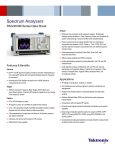
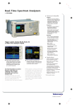
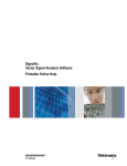
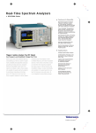
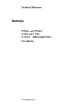
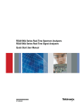
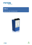
Real-Time Spectrum Analyzer
RSA3408B
Features & Benefits
Discover
DPX™ Spectrum Processing
Provides an Intuitive
Understanding of Time-varying
RF Signals with Color Graded
Displays Based on Frequency of
Occurrence
Revolutionary DPX Displays
Transients with >48,000 Spectrum
Measurements per Second
Trigger
Tektronix Exclusive Frequency
Mask Trigger (FMT) Offers Easy
Event-based Capture of Transient
RF Signals by Triggering on Any
Change in the Frequency Domain
Capture
DC to 8 GHz Frequency Range
All Signals in Spans Up to 36 MHz
are Captured into Memory
RSA3408B DC to 8 GHz Real-Time
Spectrum Analyzer with DPX™
The RSA3408B makes it easy for you
to discover design issues that other
signal analyzers miss. The revolutionary
DPX™ spectrum display offers an intuitive live color view of signal transients
changing over time in the frequency
domain, giving you immediate confidence in the stability of your design or
instantly displaying a fault when it
occurs. This live display of transients is
impossible with other signal analyzers.
Once a problem is discovered with
DPX, the RSA3408B Real-Time
Spectrum Analyzer (RTSA) can be set
to trigger on the event in the frequency
domain, capture a continuous time
record of changing RF events and
perform time-correlated analysis in all
domains. You get the functionality of a
high-performance vector signal
analyzer, a spectrum analyzer and the
unique discover-trigger-capture-analyze
capability of a Real-Time Spectrum
Analyzer – all in a single package.
Up to 1.28 s Acquisition Length
at 36 MHz Bandwidth Provides
Complete Analysis Over Time
Without Making Multiple
Acquisitions
Fully Preselected and Image-free
at all Times For Full Dynamic
Range at any Capture Bandwidth
Interfaces with TekConnect®
Probes for RF Probing
Differential IQ Input Available
Analyze
Revolutionary DPX display discovers what
other analyzers miss. Here, a WLAN Access
Point and Terminal are seen transmitting at
different power levels. Frequency of occurrence
is color-graded, indicating that the red AP is
on more often than the blue terminal.
Applications
RF Debug of Components, Modules or
Systems
Find Interference and Unknown Signals
in Spectrum Monitoring and
Management
Analyze Time-variant Behavior of
Standards-based and Other Radio
Systems
Characterize Radar and Pulsed RF
Signals
Powerful Vector Signal Analyzer
Functionality, Signal Source Analysis
and RFID-standards Support
Broad Range of Standard-specific
Options for Analysis of 3GPP, 3GPP2,
WiMax and WLAN Systems
Extensive Time-correlated
Multidomain Displays Connect
Problems in Time, Frequency,
Phase and Amplitude for Quicker
Understanding of Cause and
Effect when Troubleshooting
Power Measurements and Signal
Statistics Help You Characterize
Components and Systems: ACLR,
Power vs. Time, CCDF, PDF
Pulse Measurements Including
Pulse Width, Duty Cycle and
Pulse-to-Pulse Phase
Offline analysis available with
RSAVu Software
Real-Time Spectrum Analyzer
RSA3408B
Characteristics
Discover
The DPX spectrum processing engine brings live
analysis of transient events to spectrum analyzers.
Performing more than 48,000 frequency transforms
per second, transients as brief as 31 µs are
displayed in the frequency domain. This is orders of
magnitude faster than conventional analysis techniques. Events are color-coded by rate of occurrence
onto a bitmapped display, providing unparalleled
insight into transient signal behavior.
Trigger
The Tektronix Frequency Mask Trigger (FMT, Opt. 02)
makes it easy to trigger on signals in the frequency
domain and capture transient signals in bandwidths
up to a 36 MHz. An FMT is simply configured to
monitor all changes in frequency occupancy within
the capture bandwidth. The Power Trigger, working
in any capture bandwidth, fires at the instant in time
when the RF input signal crosses a user-set power
threshold. An external trigger is available for
synchronization to test system events.
FMT and Spectrogram of WLAN/Bluetooth. A
Frequency Mask Trigger was set to monitor
the frequency domain for any changes in
the spectrum, and it triggered on transient
interference with a WLAN signal. The spectrogram shows the time relationship
between the WLAN and transient signals,
and the spectrum display shows what was
happening at the precise moment the interfering signal was present in the band. FMT
is an essential tool for separating known
signals from unwanted interference.
The RSA3408B is your best tool for both
troubleshooting and conformance testing.
Here, a mobile WiMax analysis is performed
using RSA-IQWIMAX software.
Capture
Unlike many SA/VSA combination instruments, the
RSA3408B is fully preselected at all times for
spurious and image rejection in any combination of
capture bandwidth and frequency. Capture of small
signals in the presence of large signals is enabled
with 73 dB Spurious-Free Dynamic Range (SFDR)
and class-leading image rejection in all capture
bandwidths. Capture once – make multiple measurements without recapturing. Record lengths vary
depending upon the selected capture bandwidth-up
to 1.28 seconds at 36 MHz, 51.2 seconds at 1 MHz
or 1.42 hours at 10 kHz bandwidth with FMT/Deep
Memory Option 02.
Analyze
The RSA3408B offers analysis capabilities that
advance productivity for engineers working on
components or in RF system design, integration and
performance verification, or operations engineers
working in network or spectrum management.
Spectrograms display both frequency and
amplitude changes over time. Measurements
are Time-correlated across the frequency,
phase, amplitude and modulation domains
Analog modulation analysis and pulse
analysis are standard
2
A wealth of modulation analysis options are
available, including the UMTS W-CDMA Family
(3GPP HSUPA and HSDPA), WiMax (Fixed and
Mobile) and WLAN (802.11a/b/g/n). General
purpose modulation analysis includes support for
M-QAMs, QPSKs and the latest RFID standards
including ISO 18000-7 and 15963, plus signal
source analysis including phase noise, jitter,
and frequency-settling time. See specifications for details on measurement options
Powerful pulsed signal analysis for
characterization of Radar and other pulsed
systems. The RSA3408B automatically
measures pulse width, rep rate, pulse
power and 7 other pulse parameters.
Accessories
A wide range of Tektronix active and passive probes are supported with the RTPA2A probe adapter for your RSA3408B
in circuit-troubleshooting applications. Probe calibration factors are transferred via USB for calibrated measurements.
TekConnect
Probe Supported
P7225
P7240
P7260
P7330
P7350
P7350SMA
P7380
P7380SMA
P7313
Real-Time Spectrum Analyzers • www.tektronix.com/rsa
Frequency Range
Type
2.5 GHz
4 GHz
6 GHz
3.5 GHz
5 GHz
5 GHz
8 GHz
8 GHz
>12.5 GHz
Active
Active
Active
Differential
Differential
Differential SMA
Z-Active Differential
Differential SMA
Z-Active Differential
Real-Time Spectrum Analyzer
RSA3408B
RSA3408B: The mid-range member of the RTSA Family
Tektronix offers Real-Time Spectrum Analyzer models to meet a range of needs for frequency coverage, real-time bandwidth and dynamic range. The table below summarizes
the differences between the models. Full details of the RSA3300B and RSA6100A models are available in separate data sheets.
Specification or Feature
Freq Range
Max. Capture BW
Triggers, Standard
Triggers, Optional
Digital Phosphor (DPX) Spectrum Update
Rate, Max Span and Min. Signal Duration
Memory
Spurious-Free Dynamic Range
at Max. Capture BW
DANL, 1 GHz
ACLR (3GPP 1 DPCH)
SSB Phase Noise at Specified
Offsets at 1 GHz, dBc/Hz (Typical)
RSA3303/08B
RSA3408B
RSA6106/14A
DC to 3.0/8.0 GHz
15 MHz
Level, Free Run, External
Frequency Mask
15 MHz BW
>48,000 Spectrums/sec
15 MHz Max Span Min. Sig.
Duration: 41 us
64M/256MB
–70 dBc/15 MHz
DC to 8.0 GHz
36 MHz
Level, Free Run, External
Frequency Mask
36 MHz BW
>48,000 Spectrums/sec
36 MHz Max Span Min. Sig.
Duration: 31 us
64M/256MB
–73 dBc/36 MHz
9 kHz to 6.2/ 14.0 GHz
40 MHz standard 110 MHz Option
Level, Free Run, External(2), Line
Frequency Mask
40/110 MHz BW
>48,000 Spectrums/sec
40/110 MHz Max Span Min. Sig.
Duration: 31/24 us
256M/1 GB
–73 dBc/110 MHz
–150 dBm/Hz
66 dB
10 kHz: –108
1 MHz: –133
10 MHz: –136
8.4 Inch Screen, Keyboard,
Mouse, Front Panel
GPIB, LAN, USB(2)
Internal HDD, FDD
20 MHz BW Differential Inputs
Not Available
Not Available
–151 dBm/Hz
72 dB
10 kHz: –112
1 MHz: –135
10 MHz: –140
8.4 Inch Screen, Keyboard,
Mouse, Front Panel
GPIB, LAN, USB(2)
Internal HDD, FDD
Optional Removable HDD
40 MHz BW Differential Inputs
Standard, 421 MHz, 40 MHz BW
Up to 36 MHz BW
Option, External,
0.1 to 3 GHz 20 dB Gain nominal
Option, External,
0.1 to 3 GHz 20 dB Gain nominal
–149 dBm/Hz
79 dB
10 kHz: –110
1 MHz: –134
10 MHz: –142
10.4 Inch Touch-Screen, Keyboard,
Mouse, Front Panel
GPIB, LAN, USB(4)
Internal HDD, DVD ±RW
Optional Removable HDD
Not Available
Option, 500 MHz, 120 MHz BW
Up to 110 MHz BW, fully
corrected amplitude and phase
Option, Internal,
0.01 to 3 GHz 30 dB Gain nominal
Screen Size, User Interface
Interface Ports
Storage Media
IQ Inputs Option
IF Outputs
Digital I and Q Output
Option Bandwidth
Preamplifier
Trigger-related
Trigger Modes – Free run, Triggered (Single
or Continuous).
Trigger Event Source – RF Input, External
Trigger Input.
Trigger Types – Power Level: Frequency Mask (Opt. 02).
Trigger Position – settable from 0 to 100% of total
acquisition length.
Power Level Trigger
Level Range – 0 dBfs to –40 dBfs*1
from reference level.
Trigger Bandwidth Range – 100 Hz to 36 MHz
(equal to selected span).
Trigger Position Display Timing Uncertainty
(Power and External Trigger) – ±2 sample points.
*1 dBfs: dB relative to full scale.
Frequency Mask Trigger
(Option 02)
Mask Shape – User-defined.
Mask Point Horizontal Resolution – 1 bin.
Level Range – 0 to –60 dBfs at 10 dB/div
vertical scale.
Level Accuracy – Equal to reference level accuracy
+ frequency response over 0 to –60 dBfs range.
Span Range
Start Frequency ≥ 40 MHz – 100 Hz to 36 MHz.
Start Frequency < 40 MHz – 100 Hz to 40 MHz.
Minimum Event Duration for 100% Probability of
Trigger – 20 µs (at maximum acquisition bandwidth)
Events lasting less than minimum event duration
specification will result in degraded Frequency Mask
Trigger level accuracy.
Trigger Position Uncertainty – ± 2 Frames (For
Span = 36 MHz, uncertainty = ±40 µs).
External Trigger
Level Range – –1.5 V to +1.5 V.
Level Setting Resolution – 0.1 V.
Trigger Position Timing Uncertainty – ± 2
Samples.
Input Impedance – > 2K Ω (nominal).
Trigger Output
Voltage
HIGH – ≥ 2.0 V;
LOW – <0.4 V (Output Current <1 mA).
Capture-related
Real-Time Acquisition Bandwidth, maximum
Start Frequency ≥ 40 MHz (RF) – 36 MHz.
Start Frequency <40 MHz (Baseband) – 40 MHz.
IQ Inputs (Option 03) – 40 MHz.
A/D Converter – 102.4 MS/s, 14 bit.
Acquisition Memory Size – 64 MB (16.4 MSamples)
Standard, 256 MB (65.6 MSamples), Opt. 02.
Minimum Acquisition Length – 1024 Samples.
Acquisition Length Setting Resolution – 1024
Samples.
Real-Time Spectrum Analyzers • www.tektronix.com/rsa
3
Real-Time Spectrum Analyzer
RSA3408B
Memory Depth (time) and Maximum Time Resolution
Span
40 MHz (baseband)
36 MHz
20 MHz
10 MHz
5 MHz
2 MHz
1 MHz
500 kHz
200 kHz
100 kHz
50 kHz
20 kHz
10 kHz
5 kHz
2 kHz
1 kHz
500 Hz
200 Hz
100 Hz
Sample Rate
Record Length
Record Length
Spectrum Frame
Time Resolution
(For I and Q)
Standard
(Option 02)
(Time)
(I and Q)
51.2 MS/s
51.2 MS/s
25.6 MS/z
12.8 MS/s
6.4 MS/s
2.56 MS/s
1.28 MS/s
640 kS/s
256 kS/s
128 kS/s
64 kS/s
25.6 kS/s
12.8 kS/s
6.4 kS/s
2.56 kS/s
1.28 kS/s
640 S/s
256 S/s
128 S/s
0.32 s
0.32 s
0.64 s
1.28 s
2.56 s
6.4 s
1.28 s
25.6 s
64 s
128 s
256 s
640 s
1280 s
2560 s
6400 s
12800 s
25600 s
64000 s
128000 s
1.28 s
1.28 s
2.56 s
5.12 s
10.24 s
25.6 s
51.2 s
102.4 s
256 s
512 s
1024 s
2560 s
5120 s
10240 s
25600 s
51200 s
102400 s
256000 s
512000 s
20 µs
20 µs
40 µs
80 µs
160 µs
400 µs
800 µs
1.6 ms
4.0 ms
8.0 ms
16 ms
40 ms
80 ms
160 ms
400 ms
800 ms
1.6 s
4.0 s
8.0 s
20 ns
20 ns
40 ns
80 ns
160 ns
400 ns
800 ns
1.6 µs
4.0 µs
8.0 µs
16 µs
40 µs
80 µs
160 µs
400 µs
800 µs
1.6 ms
4 ms
8 ms
Analysis-related
Standard Measurement
Functions by Mode
Spectrum Analyzer Mode – Channel Power, Adjacent
Channel Power, Occupied Bandwidth, Emission
Bandwidth, Carrier-to-Noise Ratio, Carrier Frequency,
Spurious Search, dBm/Hz Marker, dBc/Hz Marker.
RTSA Mode – Channel Power, Adjacent Channel
Power, Occupied Bandwidth, Emission Bandwidth,
Carrier-to-Noise Ratio, Carrier Frequency, Spurious
Search, dBm/Hz Marker, dBc/Hz Marker.
RTSA with Zoom – dBm/Hz Marker, dBc/Hz Marker
DPX – dBm/Hz Marker, dBc/Hz Marker.
Analog Mod. Analysis – IQ vs. Time, AM Depth, FM
Deviation, PM, Pulse Spectrum.
Time – IQ vs. Time, Power vs. Time, Frequency vs.
Time, CCDF, Crest Factor.
Pulse – Pulse Width, Peak Power, Ripple, Pulse
Repetition Interval, Duty Cycle, Pulse-to-Pulse Phase,
Frequency Deviation, Channel Power, OBW, EBW.
Optional Measurement
Functions, Standards-based
and Offline Analysis*2
General Purpose Digital Modulation Analysis
(Option 21) Mod. Formats: BPSK, QPSK, π/4
DQPSK, OQPSK, 8PSK, 16/32/64/128/256-QAM,
GMSK, GFSK, C4FM, 2ASK, 2FSK. Standard
support: Bluetooth, TETRA, P25, 802.15.4 – EVM
(RMS, Peak, EVM vs. Time), Magnitude Error (RMS,
Peak, Mag Error vs. Time), Phase Error (RMS, Peak,
Phase Error vs. Time), Origin Offset, Frequency Error,
Gain Imbalance, Quadrature Error, Rho (ρ),
Constellation, Symbol Table, PDF: Probability of
Occurrence vs. Power Level – AM-AM, AM-PM,
1 dB Compression, Crest Factor.
RFID Analysis(Included in Option 21) ISO/IEC
18000 Part 4 Mode 1. ISO/IEC 18000 Part 6 Type
A, B, C. ISO/IEC 18092(424k). ISO/IEC 14443 Part
2 Type A, B. EPC Global Generation 1 Class 0,
Class 1. ISO/IEC 18000-7 ISA/IEC 15693 –
Maximum ERP, Spurious, Power-on and Power-down
Timing and Settling, RF Envelope On-Width, OffWidth and Period, Constellation, Modulation Depth,
Modulation Index, Symbol Rate, Bit Rate, Tari Data 0, Tari Data - 1, Eye Diagram, Symbol Table, OBW,
EBW, FSK Envelope.
Signal Source Analysis (Included in Option 21) –
Integrated Phase Noise, Random Jitter, Periodic
Jitter, Settling Time, Spurious, Real-Time Phase
Noise vs. Time (Noise-o-gram).
GSM/EDGE (Option 24) – Modulation Accuracy,
Mean Power, Power vs. Time, Spectrum due to
Modulation, Spectrum due to Switching.
CDMA2000-1X Forward/Reverse Link (Option 25) –
Channel Power,ACPR, Spectrum Emission Mask, CCDF,
Modulation Accuracy, Code Domain Power.
1XEV-DO Forward/Reverse Link (Option 26) –
Channel Power, ACPR, Spectrum Emission Mask,
CCDF, Modulation Accuracy, Code Domain Power.
TD-SCDMA (Option 28) – Channel Power, ACLR,
CCDF, Modulation Accuracy, Code Domain Power.
802.11 a/b/g/n (Option 29) – Transmit Power,
Spectrum Mask, Modulation Accuracy, OFDM Flatness
and Linearity, 802.11n Transfer Function, Transfogram,
Delay Profile, Delayogram, Transfer Efficiency.
3GPP W-CDMA Release 5 HSDPA (Option 30) –
Channel Power, ACLR, Spectrum Emission Mask,
CCDF, Modulation Accuracy, Code Domain Power,
PRACH, ACK/NACK Analysis.
*2 See separate data sheets for specifications.
4
Real-Time Spectrum Analyzers • www.tektronix.com/rsa
3GPP Release 6 HSUPA (Option 40) – Channel
Power, ACLR, Spectrum Emission Mask, CCDF,
Modulation Accuracy, Code Domain Power, Phase
Discontinuity, E-RGCH, E-HICH, E-AGCH Analysis.
RSA-IQWiMax Analysis Software – Spectrum
Mask, Spectral Flatness, Symbol Constellation,
Pilot Phase Error, Frequency Error, EVM vs. Carrier,
EVM vs. Time.
Offline Analysis
RSAVu – All measurements that can be performed on
a stored waveform can be performed with RSAVu offline
analysis software (except TD-SCDMA, Option 28).
Spectrum Mode Display
Traces, Detectors and
Functions
Traces – Two traces.
Detector – Max, Min, Max-Min.
Trace Functions – Normal,Average, Max Hold, Min Hold.
Spectrum Trace Length – 801 points (Auto mode).
Real-Time Spectrum Analyzer
RSA3408B
RF Performance
Frequency Resolution (RTSA
Mode and FFT Analysis in
Spectrum Mode)
Resolution BW Range vs. Span
(DPX)
Frequency Range – DC to 8 GHz.
Initial Center Frequency Setting Accuracy –
within 10–7 after 10 minute warm-up.
Center Frequency Setting Resolution – 0.1 Hz.
Frequency Marker Readout Accuracy –
<40 MHz ± (RE x MF + 0.001 x Span + 0.2) Hz.
≥ 40 MHz ± (RE x MF + 0.001 x Span + 2) Hz.
Note: RE: Reference Frequency Error, MF:
Marker Frequency (Hz)
Span Accuracy – ±0.3% (Auto mode).
Reference Frequency –
Aging per Day – 1 x 10⁻⁹ (after 30 days of
operation).
Aging per Year – 1 x 10⁻⁷ (after 30 days of
operation).
Temperature Drift – 1 x 10⁻⁷ (10 to 40 ºC).
Total Frequency Error – 2 x 10⁻⁷ (within one
year after calibration).
Reference Output Level – > 0 dBm.
External Reference Input Frequency – 10 MHz.
External Reference Input Level Range – –10
dBm to + 6 dBm, Spurious level must be < –80
dBc within 100 kHz offset.
Noise Bandwidth Range, RTSA Mode – 0.250545
Hz to 100.218 kHz.
FFT Performance, Spectrum Mode – Number of
samples per frame : 64 to 8192 (65,536 samples
per frame, extended resolution).
Window types – Rectangular, Parzen, Welch,
Sine-Lobe, Hanning, Sine-Cubed, Sine-to-the 4th,
Hamming, Blackman, Rosenfield, Blackman-Harris
3A, Blackman-Harris 3B, Blackman-Harris 4A,
Blackman-Harris 4B, FlatTop.
Acquisition Bandwidth
36 MHz
20 MHz
10 MHz
5 MHz
2 MHz
1 MHz
500 kHz
200 kHz
100 kHz
50 kHz
20 kHz
10 kHz
5 kHz
2 kHz
1 kHz
500 Hz
200 Hz
100 Hz
Resolution Bandwidth
(Spectrum Analysis Mode)
Stability
Frequency
Resolution Bandwidth Range – 1 Hz to 10 MHz
(auto-coupled or user-selected (arbitrary)).
Resolution Bandwidth Shape – 1 Hz to 10 MHz.
Approximately Gaussian, shape factor <5:1 (60:3
dB) typical. Rectangular, Nyquist and Root Nyquist
shapes may also be selected.
Resolution Bandwidth Accuracy – Within 6% (referenced to –3 dB BW). ±0.1% (referenced to Noise BW).
Minimum Settable Spectrum
Analysis RBW vs. Span
Extended Resolution ON
Frequency Span
> 2 GHz
> 1 GHz to 2 GHz
>500 MHz to 1 GHz
>20 MHz to 500 MHz
>500 kHz to 20 MHz
>200 kHz to 500 kHz
>100 kHz to 200 kHz
>50 kHz to 100 kHz
>20 kHz to 50 kHz
>10 kHz to 20 kHz
>5 kHz to 10 kHz
>2 kHz to 5 kHz
>1 kHz to 2 kHz
>100 Hz to 1 kHz
DPX Digital Phosphor
Spectrum Processing
Spectrum Processing Rate – 48,000/s, spanindependent.
Number of Traces – 2.
Trace Types – Color-graded bit map, +Peak, Max
Hold, –Peak, Min-Hold, Average.
Minimum Signal Duration for 100% Probability
of Intercept – 31 µs.
Span Range – 100 Hz to 36 MHz.
Resolution BW Accuracy –7%.
RBW (Min)
300 kHz
200 kHz
100 kHz
30 kHz
20 kHz
10 kHz
5 kHz
2 kHz
1 kHz
500 Hz
200 Hz
100 Hz
30 Hz
20 Hz
10 Hz
3 Hz
2 Hz
1 Hz
Residual FM – < 2 Hz p-p, typical
Phase Noise Sidebands, dBc/Hz at Specified Center Frequency (CF)
Offset
1 kHz
10 kHz
100 kHz
1 MHz
5 MHz
10 MHz
CF = 1 GHz
CF = 2 GHz
CF = 6 GHz
Spec
Typical
Spec
Typical
Spec
Typical
–105
–110
–112
–132
–138
–138
–107
–112
–115
–135
–140
–140
–103
–109
–112
–132
–138
–138
–105
–111
–115
–135
–140
–140
–97
–106
–111
–132
137
137
–99
–108
–113
–134
–139
–139
RBW
100 kHz
50 kHz
20 kHz
10 kHz
1 kHz
500 Hz
200 Hz
100 Hz
50 Hz
20 Hz
10 kHz
5 Hz
2 Hz
1 Hz
Real-Time Spectrum Analyzers • www.tektronix.com/rsa
5
Real-Time Spectrum Analyzer
RSA3408B
Amplitude
(Specifications excluding mismatch error)
Measurement Range – Displayed Average Noise
Level to Maximum Safe Input.
Input Attenuator Range
RF/Baseband input – 0 dB to 55 dB, 5 dB step.
IQ Input (Opt 03) – 0 dB to 35 dB, 5 dB step.
Maximum Safe Input Level –
Average Continuous (RF Band, RF ATT ≥10
dB) – +30 dBm.
MAX DC Voltage – RF Band, ±0.2 V, Baseband,
±5 V, IQ input, Opt. 03. ±5 V.
Maximum Measurable Input Level – Average
Continuous (RF ATT: Auto): +30 dBm.
Log Display Scale – 10 µdB/div to10 dB/div.
Display Divisions – 10 divisions.
Display Units – dBm, dBµV, Volts, Watts, Hz for
Frequency Measurements, and Degrees for Phase
Measurements.
Marker Readout Resolution, dB units – 0.01 dB.
Marker Readout Resolution, Volts units – 0.001 µV.
Reference Level Setting Range
RF – –50 dBm to +30 dBm, 1 dB step.
Baseband – –30 dBm to +20 dBm, 5 dB step.
IQ Inputs (Option 03) – –10 dBm to +20 dBm,
5 dB step.
Level Linearity over Display Range – ±0.2 dB,
spec; ±0.12 dB, typical.
Frequency Response (20 ºC to
30 ºC, Att. ≥ 10 dB)
Frequency
100 kHz to 40 MHz
> 40 MHz to 3.5 GHz
> 3.5 GHz to 6.5 GHz
> 6.5 GHz to 8 GHz
Spec
±0.5 dB
±1.2 dB
±1.7 dB
±1.7 dB
Typical
±0.3 dB
± 0.5 dB
± 1.0 dB
± 1.0 dB
Amplitude Accuracy (–20 dBm
signal, 0 dB ATT, 20 ºC to 30 ºC)
Absolute Amplitude Accuracy at Calibration Point.
RF (100 MHz) – ±0.5 dB.
Baseband (25 MHz) – ±0.3 dB.
Input Attenuator Setting Uncertainty – ±0.2 dB.
Reference Level Accuracy (–10 dBm to –50 dBm
at 100 MHz) – ±0.2 dB.
VSWR – (Att ≥ 10 dB, Preamp OFF), Typical,
< 1.4:1 (300 kHz to 40 MHz),
< 1.3:1 (40 MHz to 3 GHz),
< 1.4:1 (3 GHz to 8 GHz).
6
Distortion
3rd Order Inter-modulation Distortion – (Total
Signal Power = –7 dBm, Ref Level +5 dBm,
Attenuator adjusted for optimum performance).
Frequency – 3rd order IM.
2.0 GHz – < –78 dBc.
2nd Harmonic Distortion
(–30 dBm tone at input mixer)
Frequency – 2nd Harmonic Distortion, Typical,
10 MHz to 1.4 GHz – < –65 dBc,
1.4 GHz to 1.75 GHz – <–70 dBc.
Displayed Average Noise Level
(input terminated)
Frequency
1 kHz to 10 kHz
> 10 kHz to 100 MHz
> 100 MHz to 3 GHz
>3 GHz to 8 GHz
Preamp (Opt. 01A)
Performance (Typical)
Frequency Range
Specification
–144 dBm/Hz
–151 dBm/Hz
–150 dBm/Hz
–142 dBm/Hz
100 MHz to 3 GHz
20 dB gain, 6.5 dB
Noise Figure at 2 GHz
Residual Response
(Input Terminated, Ref. Level=–30 dBm, RBW = 100 kHz)
Frequency and Span
Specification
1 MHz to 40 MHz, Span 20 MHz
–93 dBm
0.5 GHz to 3.5 GHz, Span 3 GHz
–90 dBm
3.5 GHz to 8 GHz, Span 3 GHz
–85 dBm
Spurious Response with Signal
(Signal at Center Frequency, Span=10 MHz, Ref
Lvl=0 dBm, RBW=50 kHz, Signal Level= –5 dBm).
Signal Frequency
25 MHz
2 GHz
5 GHz
5 GHz
Spurious Response
–73 dBc
–73 dBc
–70 dBc
–70 dBc
Real-Time Spectrum Analyzers • www.tektronix.com/rsa
Adjacent Channel Leakage
Ratio Dynamic Range
(Typical, CF = 2.1425 GHz, with test signal amplitude
adjusted for optimum performance).
Signal Type,
Measurement Mode
3GPP Downlink, 1 DPCH
Real-time (Spec.)
Stepped (Typical)
ACLR
Adjacent Alternate
–66 dB –68 dB
–70 dB –72 dB
IF Frequency Response and IF Phase Linearity –
(400 MHz Center Frequency, 36.6 MHz BW, Typical).
Amplitude – ±0.3 dB.
Phase – ±2.5º.
Analog Modulation Analysis
Displays
Amplitude vs. Time,
Frequency vs. Time, Phase vs. Time
Measurements
AM
FM
+AM, – AM, Total AM, Modulation Depth
+peak, –peak, peak-to-peak, (peak-topeak)/2, rms
PM
Phase at marker
Accuracy (–10 dBfs signal, input at CF, typical)
AM
±2% (modulation depth 10% to 60 %)
FM
±1% of span
PM
±3º
Pulse Measurements
Displays – Pulse Measurement Table, Pulse Trace.
Measurements – Pulse Width, Pulse Peak Power,
On/Off Ratio, Pulse Ripple, Pulse Repetition Interval,
Duty Cycle, Pulse-Pulse Phase, Channel Power, OBW,
EBW, Frequency Deviation.
Minimum Pulse Width for Detection – 20
samples (400 ns@maximum sample rate).
Maximum Pulse Length – 260,000 samples.
Real-Time Spectrum Analyzer
RSA3408B
Inputs and Outputs
Front Panel
RF and Baseband Input Connector – N type, 50 Ω.
I and Q Inputs (Option 03) – BNC Type.
Preamp Power Connector – Lemo, 6 poles:
pin 1 = NC.
pin 2 = ID1.
pin 3 = ID2.
pin 4 = –12 V.
pin 5 = GND.
pin 6 = +12 V.
Rear Panel
Analog IF Output – BNC Type, Frequency – 421 MHz.
10 MHz REF OUT – 50 Ω, BNC, > –3 dBm.
10 MHz REF IN – 50Ω, BNC, –10 dBm to +6 dBm.
EXT TRIG IN – Ext Trig, BNC, High: 1.6 to 5.0 V,
Low: 0 to 0.5 V.
GPIB Interface – IEEE 488.2.
Trigger Out – 50 Ω, BNC, High >2.0 V, Low: <0.4
V (output current 1 mA).
Digital IQ Output (Option 05)
Connector Type – MDR (3M) 50 pin x 2.
Data Output
I data – 16 bit LVDS.
Q data – 16 bit LVDS.
Control Output – Clock: LVDS, MAX 51.2 MHz.
Control Input – IQ data output enabled, connecting
GND enables output of IQ data.
Clock Rising Edge to Data Transition Time
(hold time) – > 5 ns.
Data Transition to Clock Rising Edge (setup time)
– > 5 ns.
Note: Data from Option 05 requires application of
correction factors to IQ data to achieve similar RF
performance to RSA3408A.
Side Panel
LAN Interface Ethernet – 10/100Base-T.
Serial Interface – USB 1.1, two ports.
VGA Output – VGA compatible, 15 DSUB.
Floppy Disk Drive – 3.5 inch, 1.44 MB.
General Characteristics
Ordering Information
RSA3408B
Real-Time Spectrum Analyzer, DC – 8 GHz.
Includes: User Manual, Programmer’s Manual (On
CD), Power Cord, BNC-N Adapter, USB Keyboard,
USB Mouse, Front Cover.
Temperature Range
Operating – +10º C to +40º C.
Storage – –20º C to +60º C.
Warm-up Time – 20 minutes.
Operating Altitude
Operating – up to 3000 m (Approximately 10,000 ft.).
Non-operating – up to 12,190 m (40,000 ft.).
Safety and Electromagnetic Compatibility –
UL 61010-1; CSA C22.2 No. 61010-1-04.
IEC61010, second edition (Self Declaration).
Low Voltage Directive 2006/95/EC; EN61010-1:
2001 Safety requirements for electrical equipment
for Measurement control and laboratory use.
EC Council EMC Directive 2004/108/EEC;EN61326:
1997 Product Family Standard for Electrical
Equipment for Measurement, Control, and
Laboratory Use-EMC Requirements.
Radiocommunications Act:1992, EMC Regulatory
Arrangements, AS/NZS CISPR 11 (Industrial,
Scientific and Medical Equipment).
Power Requirements – 90 VAC to 264 VAC, 47 Hz
to 63 Hz.
Power Consumption – 400 VA maximum.
Data Storage – Internal HDD, USB ports, FDD,
Removable HDD (Opt. 06).
Weight, with all options – 20 kg (44 lbs.).
Dimensions (mm, in)
Without bumpers and feet – 215 mm (H) x
425 mm (D) x 425 mm (W).
With bumpers and feet – 238 mm (H) x 470
mm (D) x 445 mm (W).
Calibration Interval – One year.
Warranty – One year.
GPIB – SCPI-compatible, IEEE488.2 compliant.
Options – Description
Opt 1A – Preamp, External, 0.1 to 3 GHz, 20 dB
Gain, 6.5 dB NF.
Opt 02 – 65.5 Msample Deep Memory, Frequency
Mask Trigger.
Opt 03 – IQ, Differential IQ inputs.
Opt 05 – Digital IQ Output.
Opt 06 – Removable HDD (40 GB).
Opt 21 – Advanced Measurements Suite (GP Mod.
Analysis, RFID, Sig. Source).
Opt 24 – GSM/EDGE Analysis.
Opt 25 – CDMA 1X Forward/Reverse Link Analysis.
Opt 26 – 1X EVDO Forward/Reverse Link Analysis.
Opt 28 – TD-SCDMA Analysis.
Opt 29 – WLAN 802.11a/b/g/n Analysis.
Opt 30 – 3GPP Release 99 (W-CDMA) and Release
5 UL/DL (HSDPA) Analysis.
Opt 40 – 3GPP Release 6 (HSUPA UL/DL) Analysis
(requires opt 30).
Real-Time Spectrum Analyzers • www.tektronix.com/rsa
7
Contact Tektronix:
ASEAN / Australasia (65) 6356 3900
Real-Time Spectrum Analyzer
Austria +41 52 675 3777
RSA3408B
Balkans, Israel, South Africa and other ISE Countries +41 52 675 3777
Belgium 07 81 60166
Brazil & South America (11) 40669400
Application Software
and Accessories
Upgrades
RSA-IQWIMAX – LitePoint IQsignalTM Software for
Tektronix Real-Time Spectrum Analyzers.
Extra Hard Drive – Extra 40 GB Removable Hard
Drive for use with Opt. 06. Order part number
065-0802-007.
RSA3KR Rackmount – Rackmount RSA33/34B
Series Real Time Spectrum Analyzers (customer
installable).
RTPA2A – Adapter for use with TekConnect Active
and Passive Probes.
E and H Near-field probes – For EMI troubleshooting. Order part number 119-4146-00.
Preamp, External – 0.1 to 3 GHz, 20 dB Gain, 6.5
dB NF. Order part number 672-A900-00.
RSA34BUP
International Power Plugs
Opt A0 – North America.
Opt A1 – Universal EURO.
Opt A2 – United Kingdom.
Opt A3 – Australia.
Opt A4 – 240V North America.
Opt A5 – Switzerland.
Opt A6 – Japan.
Opt A10 – China.
Opt A11 – India.
Opt A99 – No Power Cord or AC Adapter.
Manuals – Order Number
Additional User Manual (Paper, English) –
071-2364-00.
Additional User Manual (Paper, Japanese) –
071-2365-00.
Service Manual (Paper, English) – 071-2366-00.
Operator Manual (Paper, Russian) – 071-2369-00.
Service Options
Opt CA1 – Provides a single calibration event or
coverage for the designated calibration interval,
whichever comes first.
Opt C3 – Calibration Service 3 Years.
Opt C5 – Calibration Service 5 Years.
Opt D1 – Calibration Data Report.
Opt D3 – Calibration Data Report 3 Years
(with Option C3).
Opt D5 – Calibration Data Report 5 Years
(with Option C5).
Opt R3 – Repair Service 3 Years (including
warranty).
Opt R5 – Repair Service 5 Years (including
warranty).
Canada 1 (800) 661-5625
Central East Europe, Ukraine and the Baltics +41 52 675 3777
Option
Central Europe & Greece +41 52 675 3777
Denmark +45 80 88 1401
Opt 1A – Preamp, External, 0.1 to 3 GHz, 20 dB
Finland +41 52 675 3777
Gain, 6.5 dB NF (customer-installable).
France +33 (0) 1 69 86 81 81
Opt 02 – 65.5 MSample Deep Memory, Frequency
Germany +49 (221) 94 77 400
Mask Trigger (customer installable).
Hong Kong (852) 2585-6688
Opt 03 – IQ, Differential IQ inputs
India (91) 80-22275577
(customer-installable).
Italy +39 (02) 25086 1
Opt 05 – Digital IQ Output (customer-installable).
Japan 81 (3) 6714-3010
Opt 06 – Removable HDD.
Luxembourg +44 (0) 1344 392400
Opt 21 – Advanced Measurements Suite
(customer-installable).
Mexico, Central America & Caribbean 52 (55) 5424700
Opt 24 – GSM/EDGE Analysis (customer-instalMiddle East, Asia and North Africa +41 52 675 3777
lable).
The Netherlands 090 02 021797
Opt 25 – CDMA 1X Forward/Reverse Link Analysis
Norway 800 16098
(customer-installable).
People’s Republic of China 86 (10) 6235 1230
Opt 26 – 1X EVDO Forward/Reverse Link Analysis
Poland +41 52 675 3777
(customer-installable).
Portugal 80 08 12370
Opt 28 – TD-SCDMA Analysis (customer-installable).
Opt 29 – WLAN 802.11a/b/g/n Analysis (customerRepublic of Korea 82 (2) 6917-5000
installable).
Russia & CIS +7 (495) 7484900
Opt 30 – 3GPP Release 99 (W-CDMA) and Release
South Africa +27 11 206 8360
5 (W-CDMA) UL/DL Analysis (customer-installable).
Spain (+34) 901 988 054
Opt 40 – 3GPP Release 6 (HSUPA UL/DL) Analysis
Sweden 020 08 80371
(requires opt 30, customer-installable).
Switzerland +41 52 675 3777
Opt IF – Installation labor for RSA34BUPxx (no caliTaiwan 886 (2) 2722-9622
bration required).
Opt IFC – Installation labor for RSA34BUPxx (with
United Kingdom & Eire +44 (0) 1344 392400
calibration).
USA 1 (800) 426-2200
Languages
Opt L0 – English Users/ Programmers Manual.
Opt L5 – Japanese Users/ Programmers Manual.
Opt L10 – Russian Manual.
For other areas contact Tektronix, Inc. at: 1 (503) 627-7111
Updated 12 November 2007
For Further Information
Tektronix maintains a comprehensive, constantly expanding
collection of application notes, technical briefs and other
resources to help engineers working on the cutting edge of
technology. Please visit www.tektronix.com
Product(s) are manufactured in ISO registered facilities.
Product(s) complies with IEEE Standard 488.1-1987, RS-232-C, and with
Tektronix Standard Codes and Formats.
Copyright © 2007, Tektronix. All rights reserved. Tektronix products are
covered by U.S. and foreign patents, issued and pending. Information in
this publication supersedes that in all previously published material.
Specification and price change privileges reserved. TEKTRONIX and TEK
are registered trademarks of Tektronix, Inc. All other trade names referenced are the service marks, trademarks or registered trademarks of their
respective companies.
12/07 HB/WOW
37W-21129-0