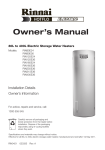
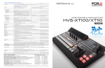
1
User’s Manual Ver.1.4.TG1 April 2015 Transgenomic Inc in collaboration with ADSTEC Corporation HANABI-PV Introduction Thank you for purchasing the ADSTEC Corporation “Metaphase Auto Spreader Mini “HANABI-PV”. We hope you will remain a satisfied customer for years to come. The chromosome specimen maker Metaphase Auto Spreader Mini (HANABI-PV) conducts cell suspension spreading automatically, simplifying a typically complicated and involved process and producing uniform specimens on slides. The chromosome metaphase Auto spreader HANABI-PV allows setting the best spreading conditions to prepare specimen slides used for cytogenetic analysis using techniques such as FISH, CGH, and G-banding. This system allows automated sample dropping of up to 20 slides per run with up to 10 different samples per run. This system applies the basic spreading technique of the manual "HANABI" Spreader that provides the optimum development condition to make the Chromosome Metaphase specimen slide. The Metaphase Auto Spreader Mini HANABI-PV consists of the spreading section, the glass slide holding drum, the dispensing section, and the spreading environment control section. The Metaphase Auto Spreader Mini HANABI-PV can be used to spread a wide variety of cells in automated fashion by setting the spreading parameters that fundamentally control key spreading conditions. Please read this manual thoroughly when you use HANABI-PV, and we hope it will bring you continued satisfaction. i ADSTEC Corporation HANABI-PV - Approved conditions of use The following conditions of use and warranty shall apply when operating our “Metaphase Auto-Spreader “HANABI-PV” (hereinafter called “the equipment”) according to this manual, unless other warranty conditions are specified in a specific contract or purchase specifications. - Warranty Warranty period The warranty period of the equipment shall be for one year, from the date of original purchase or delivery to a specified site. Scope of warranty In the event of any failure occurring due to manufacturing defect during the above warranty period, ADSTEC Corporation will replace or repair defective parts at no charge at the place of purchase. However, defects occurring under the following circumstances shall not be covered: a) When this equipment is used under conditions or in an environment or manner, or for a purpose other than that specified in this manual or specifications. b) When the defect is caused by something other than the equipment itself. c) When the equipment is modified or repaired by anyone other than our company or distribution representative. d) When the equipment is used for a purpose other than that intended. e) When the cause thereof was impossible to predict given the level of science and technology prevailing at the time of equipment delivery. f) When the defect is due to other causes for which we are not responsible, such as accidents or natural disaster. This warranty applies only to the equipment, and does not cover other damages induced by the failure of this equipment. - Limitation of liability (1) ADSTEC Corporation shall not be liable for any consequential or incidental damage caused by the equipment. (2) Concerning programmable-type products within this equipment, we shall not be liable for programs created by anyone other than our company, and any result caused by such programs. - Conditions for appropriate use (1) Do not use the equipment for any use other than that specified in the specifications. When using the equipment in combination with other systems, the user must be responsible for checking compatibility between the equipment and the other system, machine, or equipment to be used. We accept no liability for the compatibility of this equipment if this is not done. (2) The example applications presented in this manual are for reference purposes only. Be sure to check the functions and safety of the equipment before operation. (3) Ensure you fully understand all the prohibitions and precautions before use and strictly follow them during operation, in order to avoid the risk of unexpected damage to you or any third party that may be caused by improper handling of the equipment. ii ADSTEC Corporation HANABI-PV - Change in specifications The specifications and accessory lineup of the equipment described in this manual are subject to change without prior notice, when required for product improvement or other reasons. - Scope of application The above conditions of warranty apply to transactions and use of the equipment in Japan. Please contact our Sales Department for sales elsewhere. Safety Precautions Indications and meanings for ensuring safety during use of equipment Proper handling and checking are essential to ensure the equipment is used safely. This manual indicates items that may result in injury or death when the equipment is handled improperly, at three levels, namely DANGER, WARNING, and CAUTION. - Explanation of sign Indicates that if this sign is ignored and the equipment improperly DANGER operated, it may lead to imminent danger of death or severe injury. Indicates that if this sign is ignored and the equipment is improperly WARNING operated, it might lead to death or serious injury, or minor injury or physical damage. Indicates that if this sign is ignored and the equipment is improperly CAUTION operated, it might lead to minor injury or physical damage, although it is unlikely to result in serious injury. - “Serious injury” above refers to loss of sight, injury to limbs, burns, electric shock, and bone fractures associated with after effects requiring hospitalization or long-term stay in a hospital. “Minor injury” refers to injury, burns, or electric shock that are not included in the serious injuries category. “Physical damage” refers to extended damage to facilities or property. The “triangle” sign is used to warn (or caution) the user about dangers (or dangerous conditions) that may occur due to apparently improper operation or use of the equipment. iii ADSTEC Corporation HANABI-PV In addition, the following signs are also used in this manual and on the equipment surfaces. All these signs contain important information and must be followed at all times. RISK OF ELECTRICAL SHOCK Risk of electric shock under particular circumstances. CAUTION: HOT Risk of burns if this location is touched. REVOLVING BODY Risk of potential injury or property damage resulting from contact with moving parts. General prohibitions These signs indicate prohibited actions. DO NOT TOUCH GROUNDING REQUIRED If a safety ground terminal is provided, be sure to ground the ground lead. General compulsory instructions This sign indicates that the item in question requires attention. Never peel off the WARNING labels attached to the product. Important Safety Precautions WARNING (1) Always follow the directions specified in this manual when using the equipment. Do not try to operate or handle the equipment in a manner other than that specified in this manual. Do not replace any parts with other units of differing specifications, or otherwise modify the equipment. Do not use the equipment for any purpose other than that specified in this manual. Doing so may result in mechanical failure or personal injury. (2) Keep the equipment away from fire. Do not modify it in any way. (3) Do not use the equipment in a place where it may get wet. (4) Be sure to ground the equipment to prevent the risk of electric shock through current leakage. (5) In the event that any abnormal sound, smell or any other abnormal conditions are detected during use of the equipment, immediately stop operation and contact the distributor or our company. iv ADSTEC Corporation HANABI-PV CAUTION (1) The equipment is intended for use in the E.U. and U.S. and re-export is not permitted without manufacturer or distributor consent. (2) The user of this equipment must undertake training in the beginning. (3) Periodic maintenance is vital to ensure the equipment can be used safely for an extended period. Please arrange a check to this equipment once in one year by the manufacturer or the professional skill person in the agency maintaining the equipment. The maintenance contract is separately necessary. (4) We do not accept any liability, other than for equipment repair, for any damage caused by equipment failure. (5) Ensure the equipment is always operated according to the order and method specified in this manual. Failure to do so may result in the equipment malfunctioning or failing. (6) Only specially trained personnel should remove or replace parts. (7) Do not cover the openings used for ventilation (aspiration and air compressor pump outlets, and air vents on the side and bottom of the equipment). (8) Before connecting the power cable or checking the equipment, ensure it is fully switched off. Before checking the equipment, also unplug the cable from the socket. (9) Please remove equipment inlet side of the power cable in an emergency (smoking and ignition, etc.). (10) To completely stop the equipment, turn the power switch on the front side of the equipment OFF and then unplug the cable from the socket. (11) Pull the power cord from its inlet connection to the main body of the equipment immediately in an emergency (smoking, ignition, etc.). (12) Please wipe off the unit with a paper towel etc. when reagent or sample is spilled in the equipment. Wear chemically-compatible protective gloves for handling the reagents and the samples. Please flush immediately with water when reagent contacts clothing or the skin. (13) Please clean the unit with a paper towel etc. wetted with ethanol when dirt adheres to the plastic and the metal parts of the equipment. Or, please wipe with a water-dampened cloth or paper towel. Do not use an organic solvent --this might discolor or damage the plastic. (14) The expected lifespan of the equipment is five years and it should be replaced when this period has passed. (15) Do not disclose any of the contents of this manual, in whole or in part, to any third party without the prior consent of ADSTEC Corporation. (16) The contents of this manual are subject to change without prior notice at any time, due to improvement of equipment specifications or for other reasons. (17) If you have any query or lack of understanding regarding any of the contents of this manual, please contact the distributor or our Sales Department. Chemical information: Fixative solution: Acetic acid and methanol mixture ratio 1:3. Acetic acid (CH3COOH): Physical properties mp(℃): 16.7 bp(℃): 118 Specific gravity (20/4℃): 1.049 Flash point (℃) 39 (closed cup Merck) Methanol CH3OH: Physical properties mp(℃): -97.8 bp(℃): 64.7 Specific gravity (20/4℃): 0.7915 Flash point (℃) 11℃ and explosion range: 6.7-36.5v/v% Additionally, the methanol is mixed with water at an arbitrary rate. v ADSTEC Corporation HANABI-PV CAUTION FOR CHEMICALS USED WITH THIS SYSTEM When acetic acid and methanol are mixed, always prepare in an area of suitable ventilation and fumes exhaust. Take great caution in handling to avoid ingestion and take precaution to avoid contact with skin. Under most regulatory jurisdictions, acetic acid with methanol is a hazardous mixture. 【 measures for safety 】 ・Do not handle these chemicals without first consulting and fully understanding the safety data sheets for acetic acid and methanol. ・Fully review use instructions concerning acetic acid and methanol before using them with this equipment. ・Do not eat, drink, or smoke while using the acetic acid and the methanol. ・Avoid all possible sources of ignition, including spark, static discharge, open flame and hot surfaces.; ・In areas of high fumes use explosion-proof electrical equipment for the ventilation system and the lighting. Prevent ignition by static discharge and from sparks. ・Avoid personnel exposure by utilizing appropriate personal protective equipment. ・Avoid contact with skin and eyes. Wear chemically-resistant protective gloves and protective glasses,. ・Use only in areas of sufficient ventilation; wear suitable respiratory equipment as needed. ・Avoid inhalation of mist, spray, and fumes from these chemicals. ・Wash your hands well after handling. Installation Precautions To ensure extended use of the equipment (1) Before unpacking, transfer the equipment to a flat area close to the installation site. (2) After unpacking, ensure that the following items are all included: - Main body of HANABI-PV………………....…..……x1 - Power cable……………………………….…………x1 - Sample Tip Holder……………………….………….x1 - Tip Reject box…………………………….………….x1 - Humidifying Water Bath………………….…………x1 - Slide Cassette………………………….…………….x4 - Pipet Guide (Flat, 1 spot).......................................x1 - Rear door key………………………….………….….x1 - Tip Box (96 tips included)…………….…………….x3 - Sample tubes and slides for testing……………….x1 Options: (All included when purchased each option.) ■ID reader - ID Reader for sample tubes……….………….x1 - ID Reader for glass slides……….………….x1 ■Pipette Guide - Tilting Pipette Guide (5 ゚, 1 spot)……………..x1 - Tilting Pipette Guide (10 ゚, 1 spot)……………..x1 - Tilting Pipette Guide (15 ゚, 1 spot)……………..x1 - Tilting Pipette Guide (Optional angle, 1 spot)...x1 - Tilting Pipette Guide (Flat, 2 spot)……………..x1 ■Label printer - Label Printer……………………………….…….x1 - Label (4000 pieces)……………………….…….x5 - Label ribbon……………………………….….….x3 vi ADSTEC Corporation HANABI-PV Also ensure that the product and accessories are free from any damage or deformation. (3) Choose an appropriate location for installation and ensure the equipment is installed on a level surface. In particular, the following sites should be avoided: ● ● ● ● ● ● ● Exposed to high temperature and humidity Exposed to strong vibration or impact Potentially exposed to salt content or corrosive gas Inclined (uneven) areas Areas in the vicinity of radio equipment (which may result in the equipment to malfunction) Dusty areas Confined spaces (The equipment requires space around the exhaust outlets to enable air cooling.) WALL (4) Please allow space at left ( > 1.5m), at right ( > 1.0m), and at back ( > 0.2m) from adjacent walls to the side of this equipment to allow adequate ventilation and room air movement. > 0.2m > 1.5m Metaphase Metaphase Auto Auto Spreader Spreader Mini HANABI-PV HANABI-PIV > 1m FRONT (5) Please move the equipment with the assistance of three or more people. Please lift and push at the four corners of the equipment. The cover might dent if the cover is pushed. Within its crate, please move safely and carefully via use of a forklift, etc when you move the unit over a significant distance. The forklift must penetrate two forks forward under the equipment backward (Or, from the rear side forward). Metaphase Auto spreader Forklift HANABI-PIV Metaphase Auto Spreader Mini HANABI-PV (6) Method of connecting safety earth and power supply. Please connect the safety earth by the following method for the prevention of electric shock. -The safety earth is connected if the power plug connected to the power outlets has three poles. -The conversion plug (3-prong plug →2-prong plug) is used when power outlets have only two poles. In this situation, connect the earthing cable of the conversion plug to an earth terminal in the building. (7) This equipment is only for indoor use. The equipment cannot be used outdoors. vii ADSTEC Corporation HANABI-PV Operating Precautions (1) Ensure more than 30 minutes are allowed for the preliminary run. (2) Never open the door during operation (main process). User’s Manual Revision History The manual revision symbols are listed on the last page of this manual. User’s Manual number: HANABI-PV Version 1.3 August 11, 2014 Revision symbol V1.1 V1.3 Revision date May 20, 2013 August 11, 2014 V1.4 November 25, 2014 V1.4.TG0 February 23, 2015 V1.4.TG1 April 10, 2015 Revision page / Contents Revise table at Range of setting items Add description of air ventilation after spreading Revise screen at “3.3 Operation progress” Replacement of some pictures Revise screen at “3.10 Dry-Index setting” Correct mistaken character on page 20. Revise English wording for clarity, and provide further instruction on setting of run parameters Revise English wording for clarity, and provide further instruction on setting of run parameters viii ADSTEC Corporation HANABI-PV Metaphase Auto Spreader Mini HANABI-PV User’s Manual Table of Contents Introduction ....................................................................................................................................... i - Approved conditions of use ............................................................................................................ ii - Warranty contents.......................................................................................................................... ii - Limitation of liability ..................................................................................................................... ii - Conditions for appropriate use...................................................................................................... ii - Change in specifications ............................................................................................................... iii - Scope of application....................................................................................................................... iii Safety Precautions .......................................................................................................................... iii Important Safety Precautions ........................................................................................................ iv Chemical information: ..................................................................................................................... v Installation Precautions ................................................................................................................. vi Operating Precautions .................................................................................................................. viii User’s Manual Revision History .................................................................................................. viii 1. Explanation of the terms ................................................................................................................. 1 2. Operational procedures ................................................................................................................... 2 2.1. Name of operating part ............................................................................................................. 2 2.2. Warning indication .................................................................................................................... 2 2.3. Preparation ................................................................................................................................ 3 2.4. Procedure ................................................................................................................................... 5 2.5. Procedure of spreading environment ....................................................................................... 7 3. Explanation of the operation panel ................................................................................................ 9 3.1. Opening Screen ....................................................................................................................... 10 3.2. MAIN........................................................................................................................................ 11 3.3. Operation progress .................................................................................................................. 13 3.4. Setting MAIN .......................................................................................................................... 14 3.5. Sample 1/ 2, ¾, 5/6, 7/8, 9/10 setting ..................................................................................... 15 3.6. Dry-Index setting .................................................................................................................... 16 3.7. Stir setting ............................................................................................................................... 18 3.8. Pre-rinse setting ...................................................................................................................... 19 3.9. Sample setting ......................................................................................................................... 20 3.10. Dropping setting.................................................................................................................... 21 3.11. Spreading setting .................................................................................................................. 22 3.12. Spreading spot setting .......................................................................................................... 23 3.13. Dry-Index FAN setting ......................................................................................................... 24 3.14. Numeric keypad .................................................................................................................... 25 3.15. Progress display messages ................................................................................................... 26 3.16. Explanation of Dry-Index Parameter…………………………………………………………..27 4.Specifications ................................................................................................................................ 28 4.1. Main specifications.................................................................................................................. 28 4.2. Outline ................................................................................................................................... 299 4.3. Range of setting items ............................................................................................................ 30 5.Appendix ...................................................................................................................................... 311 5.1. Bar Code reader ...................................................................................................................... 31 5.2. Description of bar code label .................................................................................................. 32 5.2.1. Material of bar code label................................................................................................. 32 5.2.2. Bar Code labeling position ............................................................................................... 32 5.3. X-Y movement of dispenser robot ........................................................................................ 343 ADSTEC Corporation HANABI-PV 1. Explanation of the terms No. (1) Terms Dry-Index (2) Spreading (3) Protocol (4) Air vents (5) (6) (7) (8) (9) (10) (11) Code Reading Sample ID Sample Tube Glass slide Tip Dispenser Sample/Mode Sensor (12) Tip Sensor (13) (14) Pipette guides for angle of gradient/number of drops Humidifying Water Bath (15) Sample Tip Holder (16) (17) (18) (19) (20) (21) (22) (23) (24) (25) (26) Tip Reject Box Slide Cassette Code Reader Spreader Chamber Chamber Drum Dispenser Robot Depressed area for Sample Tip Holder Pipetting Stirring Pre-rinse Tip Empty Air Volume (27) (28) (29) (30) (31) BASE BATH WALL Home Return Spreading Mode (32) (33) (34) Sample volume Number of Drops Additional Fixative (35) (36) Drying Time Humidifying Water Bath FAN Exhaust FAN (37) Meaning/Explanation Index of dryness. Dry-Index is inversely proportional to the absolute moisture level within the Slide Chamber, The higher the humidity in the Slide Chamber, the lower the Dry-Index Value. A value of “10” for Dry-Index is equivalent to a relative humidity level of 50% at 30 degrees C, +/- a level of accuracy for the relative humidity. Drop the cell suspension on the glass slide, expand the chromosome in the cell, and fix to the surface of the glass slide Independent setting including spreading conditions (dropping sample volume, spreading mode and Dry-Index value, etc.) possible to set up to 20 protocols into the “Function No.” on the setting MAIN screen. Holes for taking air into spreading chamber. There are two holes in the back of the equipment. Controlled ID function for sample tubes and glass slides.. Bar code or two-dimensional code to identify each sample. Tube with the sample. 15mLconical tube is used. Clear glass for sample preparation. Dimensions are 76mm x 26mm (t = 0.8 – 1.2mm). Disposable tip made of PP installed on the end of the dispenser The nozzle for stirring and dispensing the sample with fitting a tip on end. The sensor which is located next to dispenser to check spreading mode and detection of the sample tubes. The sensor which is located in the upper part of tip reject box to check presence or absence of a tip on the dispenser. The pipette guide which is located over the spreader chamber. It is also used for confirmation of spreading mode. The container with distilled water or deionized water which is placed into spreader chamber. The rack to set the sample tubes, fixative solution tube, tips and slide reject BOX. It can be set to a maximum of 10 sample tubes, 1 fixative solution tube and maximum 20 tips. The BOX to collect robotically discarded pipette tips. The cassette in which five glass slides are placed and it is mounted on the BASE. The reader to read bar codes and 2-dimensional code on sample tubes and glass slides. The location to drop the sample covered with clear acrylic on the left of working space. The BASE block to mount four slide cassettes. The moving unit with dispenser and sensor. Concave region for setting Sample Tip Holder on the right of working space. Mixes the sample for Pipetting by repeated aspiration and discharge with the dispenser. Rinse the tip by sample. Eject all of the sample inside tip. Air volume to aspirate the sample by dispenser to avoid the sample falling down before spreading. The location in which to set the slide cassettes and glass slides to spread the samples. Humidifying Water Bath of spreader chamber. Floor and wall of spreader chamber. The movement to return to the origin or home position on each unit of the equipment. The mode of angle of gradient/number of drops. Spreading mode is robotically-determined after confirmation of the information key. Amount of one sample dropped when spreading the sample on a glass slide. The number of drops on a glass slide. In other words, it is called “Spot”. Spreading method of dropping fixative before or after dropping the sample on a glass slide. Time for drying the glass slides on which samples were dropped. Fan for humidifying the chamber. It is also called Dry-Index FAN1. FAN to adjust the amount of exhaust air from the chamber. FAN2. 1 It is also called Dry-Index ADSTEC Corporation HANABI-PV 2. Operational procedures 2.1. Name of operating part (1) Operation panel The operation panel includes its display with touchscreen entry functions. (2) Power switch This switch is used to turn the main power ON or OFF. The equipment will activate about 45 to 80 seconds after the switch is turned on. (3) Light switch This switch illuminates inside the robotics section. (4) BASE controller Adjustable heat controller for the slide support BASE (5) BATH controller Adjustable heat controller for the Water BATH tank (6) WALL controller Adjustable heat controller for the slide chamber WALLs (7) Front door To open the front door, hold the handgrip (right side) and the recessed portion of handle (left side), then pull down on the door to open. To close the door, perform procedure steps in the reverse order. 2.2. Warning indication On the surface of the equipment, warning indications are provided at the points shown in the figure. 2 ADSTEC Corporation HANABI-PV 2.3. Preparation The following items should be prepared. (Refer to figure "Name of each part" on the next page.) (1) Humidifying Water Bath (Tank) Put distilled water or the deionized water in Humidifying Water Bath (Tank) to the mark level. (2) Glass slides Open the front door and chamber cover, and then remove slide cassettes from the BASE. Set slide cassette to BASE block in the correct order because each slide cassette has number and BASE block has keys to attach. Slide cassette are mounted in the latch to BASE block both ends. Set the frosted area of the glass slides to the back side when installing slide cassettes. Hold two latches of the slide cassette when installing and removing as shown in the right figure. During operation BASE block is rotated according to the dropping process number. (3) Tip Reject Box Be sure to empty it. (4) Sample Tubes Set sample tubes into sample holders. The sample tubes are sequentially used from holder No.1. Additional Fixative tube is set on holder No. 11. Be sure to set it on holder No. 11 in case of performing additional fixative dropping. And also set the tubes without leaving space. ID code reading will be terminated with unfilled places. (5) Tips Set tips into the sample tip holder. The tips are used from No.1 to toward back side and right side, and make sure to set the tips without leaving space. ■Pipette guides for angle of gradient/ number of drops Change the pipette guide as needed. Angle of gradient can be set by 5 degrees, 10 degrees and 15 degrees. The number of drops can be chosen one or two. CAUTION Use accompanying screw driver in case of replacement of pipette guides which are for angle of gradient/number of drops. Be careful not to drop screws into the chamber when replacing the pipette guide. ■ About optional ID label Stick the same ID code label on glass slides and a sample tube by using bar code or two -dimensional code label. For example, in case of preparation two slides in one sample, it is necessary to be provided three pieces of same ID code. (Refer to “5.2. Description of code label” in this manual regarding labels and labeling position.) 3 ADSTEC Corporation HANABI-PV [Name of each part] 4 ADSTEC Corporation HANABI-PV 2.4. Procedure The typical operation flow is as follows: (1) Power on the equipment. (2) Insert Humidifying Water Bath with distilled water or deionized water. (3) Warm up the equipment for about 30 minutes. (4) Prepare slides and tubes containing samples by applying bar coded labels. Prepare tips and tip rejects Box. (5) Perform home return “3.2. MAIN”. It can be also performed per “3.3. Operation progress”. (6) Detach each slide cassette and set glass slides onto each slide cassette by rotating BASE with pressing “Rotation” button depending on the slides. Chamber cover needs to be closed at the time of rotating drum part. (7) Set Tip reject Box. (8) Set tubes containing samples and sample tip holder containing tips. Be sure to set additional fixative tube on holder No. 11 when dropping additional fixative . (9) Press “Configuration” key on “3.2. MAIN”. Set various items such as number of slides, add fixative volume, choice of adding fixative, sampling speed etc. (10) After setting items setting, return to “3.2. MAIN” and press “START” switch to start main process (a “RUN”). (11) A user can switch between “3.2. MAIN” and “3.3. Operation progress” screen during a run. The “STOP” key is also effective during this process. (12) “Completion” is displayed on the “3.3. Operation progress” screen after completion of spreading on all the glass slides. (13) Detach each slide cassette by rotating BASE with pressing “Rotation” button. Then remove the glass slides. (14) Take sample tubes and additional fixative tube out from sample tip holder. Empty Humidifying Water Bath and Tip reject Box in case of termination for the operation. And then power off the equipment. 5 ADSTEC Corporation HANABI-PV * After spreading for the day is over, front door and spreading chamber cover are opened for ventilating the inside of the instrument and the spreading chamber. Please execute this step after confirming robot part is located right and back Side. This step is necessary to maintain stable operation of this instrument. When using the instrument again, please turn ON the power supply after closing the chamber cover and front door. 6 ADSTEC Corporation HANABI-PV 2.5. Procedure of spreading environment (Slide Chamber) Spreading environment setting is as follows. This equipment controls Dry-Index value as parameter to determine the optimum value. It is most important factor controlling the speed of drying the dropped samples. (1) (2) (3) (4) (5) (6) (7) (8) (9) (10) Remove the Humidifying Water Bath from the unit. Pour distilled water (or deionized water) into the Water Bath, filling to dot. Then place it into the unit once again. Be careful not to spill while placing it back into the unit. Turn on the power and push “Origin return” button to return the unit’s robotics to its “home position”. Allow unit to warm up for 20 to 30 minutes. Heating control will start immediately when the unit is powered on. Check each value of BASE, BATH and WALL on controllers in front of the panel. Push <∧>, <∨> keys in case of changing each value. The typical, optimum values for each temperature controller is as follows: BASE: 15 (Setting range is10 to 15) A value of “10” is about 30 °C. BATH: 14 (Setting range is10 to 15) A value of “14” is about 34 °C After pressing <START> key, the BATH Value is auto-set based on the Dry-Index Setpoint Value. For details, refer to the Hanabi PV Maintenance Manual section 3.15, “Temperature Bank Setting” WALL: 15 (Setting range: 10 to 15) A value of “15” is about 35 °C Dry-Index: 9.0 (Setting range: 4 to 16) Check spreading condition by changing suitable value. Preparation of accessories a. Pour distilled water (or deionized water) into Humidifying Water Bath after detaching from the equipment. Then set it to the equipment again. b. Set glass slides onto each slide cassette as refer to “3.2. MAIN”. Detach slide cassettes when loading glass slides. Push ”Rotation“ switch when rotating the BASE. c. Set empty reject Box, sample tubes containing samples and sample tips holder loaded with tips. Be sure to place an additional tube holding Fixative in holder Slot 11 when additional fixative dropping is selected. Check to see that the Dry-Index value approaches the setpoint value within a few minutes Once the Dry-Index value reaches the setpoint value, the slide chamber will be optimum. When the Dry-Index value is stable but below the Dry-Index setpoint value, increase the Dry-Index FAN 2 Output 1 Ratio by 5 to 10% by entry on the touchscreen panel. When the Dry-Index value is stable but well above the setting value, reduce the Dry-Index FAN 2 Output 1 Ratio by 5 to 10%. Adjust the output ratio of Dry-Index FANs to reach a suitable stable airflow according to “3.17. Dry-Index FAN setting”. Push the <SAVE> button each time after changing values. Typically, optimum values for the FANs are as follows: Dry-Index FAN 1 Output ratio1 : 50 (Setting range: 50 to 70) Dry-Index FAN 2 Output ratio1 : 30 (Setting range: 30 to 50) 7 ADSTEC Corporation HANABI-PV Schematic diagram of Dry-Index control The purpose of the Dry-Index control is to make the atmosphere most suitable for spreading within the slide chamber. It does this by regulating the amount of fresh air drawn into the chamber and is blown over the Humidifying BATH as it is mixed with the air that comes from air flow FAN and vaporized air from BATH. The amount of ventilation air that enters from the air intake holes (at back of unit) is therefore controlled by the Dry-Index Control FAN and it then stabilizes drying speed based on BASE temperature. There is a limit to the range of Dry-Index control that can be achieved with the Dry-Index control FAN; therefore BATH temperature, which is controlled manually by adjustment of the BATH value, needs to be decreased or increased by the user to grossly adjust the amount of humidity loaded by evaporation from the Humidifying bath. This is further manually adjusted by the user in adjustment of the airflow of FAN1, which is the FAN that regulates the rate of airflow across the Humidifying Bath. 8 ADSTEC Corporation HANABI-PV 3. Explanation of the operation panel This section describes how to use the operation panel of the Metaphase Auto Spreader Mini HANABI-PV. The description is based on the following format: (#) Operation Screen Title Panel Layout Image display of the operation panel Indication of selected key, setting range, etc. Description < >: Indicates the name of the selected key. [ ]: Indicates the name or description of an item. * : Indicates a supplementary explanation. (Note) : Indicates particularly important information to be aware of. Sentences to be paid special attention to will be indicated in RED or BLUE. 9 ADSTEC Corporation HANABI-PV 3.1. Opening Screen This screen is displayed when the equipment is turned ON. It automatically executes tip removal, returns the robotics to the origin and reads the key that is on the pipette guide for slide angle and number of drops. Then the dispenser robot returns to the origin position, and then the screen switches to “3.2. MAIN”. 10 Transgenomic / ADSTEC Corporation HANABI-PV 3.2. MAIN This screen displays current status. Caution Be careful not to spill water into the equipment when installing the Humidifying Water Bath. [Spreading Mode]: Spreading mode displays the information read from the key of the pipet guide for angle of gradient/number of drops when the power is turned on. [Additional Fixative]: Additional Fixative mode is displayed as set in Section 3.15. “Spread setting”, displays one of the following: No (no additional fixative), Before (Add fixative before sample dropping) or After (Add fixative after sample dropping) Time to be added dropping will be performed before around 44 seconds in case of choosing “Before”, or after around 60 seconds in case of choosing “After”. [Dropping Mode]: Dropping mode can display Intermittently: No ID reader options It drops depending on number of setting. Suction sample volume is for one slide even though the sample is dropped on multiple slides. ID reader options It drops on matched slides based on ID that is read by the code reader. Suction sample volume is for one slide even if the same ID is adjacent to. [Dry-Index SV]: Displays Dry-Index set point value. [Dry-Index PV]: It displays Dry-Index Present value. [BASE Value]: When the measured value of BASE is at or above the set value, “OK” is displayed. When the measured value of BASE is less than its set point value, “NG” is displayed. 11 Transgenomic / ADSTEC Corporation HANABI-PV The BASE set point value is displayed on the controller lower front panel. [BATH Value]: When the BATH measured value is at or more than its set point (SV) value, “OK” is displayed. When the BATH measured value is less than its set point value (SV), “NG” is displayed. The BATH set point value is displayed on the controller lower front panel. [WALL Value]: When the WALL measured value is at or more than its set point value (SV) value, “OK” is displayed. When the WALL measured value L is less than its set point value (SV), “NG” is displayed. The WALL set point value of WALL is displayed on the controller lower front panel. [Pause Switch]: In case “STOP” switch is not pressed, “OK” is displayed other than when “STOP” is pressed In case “STOP” switch is engaged, “NG” is displayed after “STOP” is pressed. [Door Switch]: In case the front door is closed, “OK” is displayed. In case the front door is opened, “NG” is displayed. <START> Key: Press and hold the key for a few seconds to start the main operation. It is not necessary to press and hold the key for a few second when restart the operation. <STOP> key: The operation forcibly stops when pressing and holding the key for a few seconds. When progress status is “Pause”, pressing and holding the key for a few seconds unpauses the condition. <Configuration> key: The screen is switched to “3.4. Setting MAIN”. It becomes invalid during main process running. <Rotation> key: Rotate the drum of spreader chamber. It becomes invalid during main process running. <Next> key: The screen is switched to “3.3. Operation progress”. <Origin Return> key: It returns to home position. It becomes invalid during main process running. Caution In a case of setting “after” (Add fixative after sample dropping) as Add Fixative with 10 samples and 20 slides, the sample and add fixative solution weren’t dropped on the final slide. Please be careful. 12 Transgenomic / ADSTEC Corporation HANABI-PV 3.3. Operation progress This screen can be checked to assess the operation’s progress. This screen is not automatically displayed after pressing[START] key on “3.2. MAIN” screen Press [NEXT] at the Main screen to get to “Operation Progress” [Slide Glass Status]: Displays the status of processing the glass slides. The displayed number means “BASE No.- Slide No.”.(slides are dropped from the RIGHT Side and progressing to the LEFT as shown in this display. The “Base No.” corresponds to the engraved number (1, 2, 3, or 4) on the BASE cylinder. [Sample Status]: Displays the status of processing the sample tubes. [Sample QR read]: Displays the status of reading the QR code on the sample tubes. [Progress status]: Displays the overall status of the sample run’s progress. “Completion” is displayed in this field in the screen representation above. Please refer to section “3.15. Progress Display” about the other kinds of progress displays. <START> key: Press and hold this key for a few seconds to start a sample run. It is not necessary to press and hold the key for a few second when restarting a <STOP>ped operation. <STOP> key: A user can forcibly stop a sample run’s operation by pressing and holding the <STOP> key for a few seconds. Once the Progress status shows “Pause”, pressing and holding the <STOP> key again for a few seconds unpauses the “PAUSE” condition. <Rotation> key: Rotates the drum cylinder of the spreading chamber. It becomes inactivated during a sample run. <Back> key: This key switches the screen to “3.2. MAIN”. <Origin Return> key: This key returns the system’s robotics to its home position. It is inactivated during a sample run 13 Transgenomic / ADSTEC Corporation HANABI-PV 3.4. Selecting a Pre-set Run Protocol This screen is used to access (or create) saved protocols. Saved protocols retain system settings for reading code, sample dropping parameters, run conditions and working speeds. [Function No.]: Select protocol number. <READ> key: Protocol setting values are read based for the selected Function Number. <SAVE> key: Current settings, such as sample operation conditions and working speed are saved into the selected function number. <ALL RESET> key: Sample settings and operating conditions of the selected Function No. are reset to system default values based on the settings in “3.10. Dropping setting”. [reading CODE]: Default is set to use Bar code ID Read function for sample tubes and glass slides. This “sample (bar)Code ID Reading” can be switched “ON” or “OFF” by pressing “Num Input” key when cursor is blinking over the ON section. Caution In case of existing same ID tubes in sample tip holder, front side tube (tube read ID by tube reader in first) is given preference for dropping sample. Please be careful that posterior tube wasn’t executed dropping sample at that time. <Sample Setting> key: The screen is switched to “3.5. Sample 1,2 setting”. <Operation Condition> key: The screen is switched to “3.10. Dry-Index setting”. <↑> key: Move a cursor to upward <↓> key: Move a cursor to downward <Num Input> key: This key is used for alteration of the value which is on the cursor. The screen is switched to “3.18. Numeric keypad”. <TOP> key: The screen is switched to “3.2. MAIN”. 14 Transgenomic / ADSTEC Corporation HANABI-PV 3.5. Setting Parameters for Sample 1, 2 (Dispensing) This screen is used to set the parameters for sample No. 1 and No. 2. [Number of glass]: Set the max number of glass slides to be spread. [Add fixative volume (μl)]: Set fixative volume in case of additional spreading. This setting value is not reflected in case additional fixative dropping is set as “No” on “3.15. Spreading Setting”. [Sample volume (μl)]: Sample dropping volume can be set. [Prepared sample volume (ml)]: Set the amount of sample volume contained in the sample tube in advance. <↑> key: Move a cursor to upward <↓> key: Move a cursor to downward <Num Input> key: This key is used to alter the value which is on the cursor. The screen is switched to “3.18. Numeric keypad”. <Save> key: Save setting values. Press <Save> key whenever changing setting values. <Back> key: The screen is switched to “3.9. Sample 9, 10 setting”. <Next> key: The screen is switched to “3.6. Sample 3, 4 setting”. <TOP> key: The screen is switched to “3.2. MAIN”. The screens for samples 3 and 4, 5 and 6, 7 and 8, and 9 and 10 function the same. 15 Transgenomic / ADSTEC Corporation HANABI-PV 3.6. Dry-Index (Control) Parameter Settings This screen is used to set Dry-Index. Control Parameters Description and function [Dry-Index SV]: Enter Dry-Index set point value [Dry-Index Set upper range level for proceeding to dropping sample based Dropping range High]: on Dry-Index set point value, see figure below [Dry-Index Set lower range level for proceeding to dropping sample based Dropping range Low] on Dry-Index set value, see figure below [Proportional band] It is the inverse of the proportional control of fan speed of exhaust FAN2. The lower the PB is the faster the fan changes to push Dry-Index to the set value. PB = 100/KC, where KC = controller gain of this fan speed control. [Integral time]: It is controller time constant of the exhaust FAN to eliminate the difference between the Dry-Index current value and Dry-Index setting value. It can be corrected in a short period of time by setting a short time. However it is easy to make the control unstable. On the other hand it takes a long period of time to reach the set point in case of setting a long time. However it is easy to make the control stable. <↑> key: Move a cursor to upward <↓> key: Move a cursor to downward <Num Input> key: Select this key to alter the value the cursor is on. Selecting switches to the Numeric keypad entry screen. <Save> key: Save the entered settings. Press the <Save> key whenever changing setting values. <Back> key: The screen back switches to “3.6. Dry-Index FAN setting”. <Next> key: The screen switches to next screen, “3.7. Stir setting”. <TOP> key: The screen switches to “3.2. MAIN”. 16 Transgenomic / ADSTEC Corporation HANABI-PV Figure 3.6.b – How the dropping range “high” and “low” level parameters function 17 Transgenomic / ADSTEC Corporation HANABI-PV 3.7. STIR Parameter Settings This screen is used to set parameters for pipette mixing before sample aspiration. [Number of times]: Set the number of times of pipette mixing. [Stir Speed]: Set pipetting dispense speed. [Stir Volume]: Set the amount of one pipette dispension. Skips stirring movement when 0 is set on this value. [Stir Height]: Set dispenser height when pipette stirring. <↑> key: Move a cursor to upward <↓> key: Move a cursor to downward <Num Input> key: This key is used to alter the value which is on the cursor. The screen is switched to “3.18. Numeric keypad”. <Save> key: Save setting values. Press <Save> key whenever changing setting values. <Back> key: The screen is switched to “3.10. Dry-Index setting”. <Next> key: The screen is switched to “3.12. Pre-rinse setting”. <TOP> key: The screen is switched to “3.2. MAIN”. 18 Transgenomic / ADSTEC Corporation HANABI-PV 3.8. Pre-rinse setting Use this screen to set parameters for pre-rinse before starting sample aspiration. [Pre-rinse Speed]: Set the speed of pre-rinse. [Pre-rinse Volume]: Set the amount of pre-rinse. Pre-rinse movement skips when 0 is set on this value. [Pre-rinse Height]: Set pre-rinse height. [Tip Empty Volume]: Set the amount of spouting after pre-rinse. [Tip Empty Height]: Set the height of spouting when pre-rinse. <↑> key: Move a cursor to upward <↓> key: Move a cursor to downward <Num Input> key: This key is used to alter the value which is on the cursor. The screen is switched to “3.18. Numeric keypad”. <Save> key: Save setting values. Press <Save> key whenever changing setting values. <Back> key: The screen is switched to “3.11. Stir setting”. <Next> key: The screen is switched to “3.13. Sample setting”. <TOP> key: The screen is switched to “3.2. MAIN”. 19 Transgenomic / ADSTEC Corporation HANABI-PV 3.9. Sample setting Use this screen to set the parameters for sample aspiration. [Sample Speed]: Set sample aspiration speed. [Add Air Volume]: Set air aspiration volume for dripping prevention after sample aspiration. [Sampling Height]: Set aspiration height of the sample. [Add Fixative Height]: Set aspiration height for additional fixative solution. <↑> key: Move a cursor to upward <↓> key: Move a cursor to downward <Num Input> key: This key is used to alter the value which is on the cursor. The screen is switched to “3.18. Numeric keypad”. <Save> key: Save setting values. Press <Save> key whenever changing setting values. <Back> key: The screen is switched to “3.12. Pre-rinse setting”. <Next> key: The screen is switched to “3.14. Dropping setting”. <TOP> key: The screen is switched to “3.2. MAIN”. 20 Transgenomic / ADSTEC Corporation HANABI-PV 3.10. Dropping setting Use this screen to set parameters for sample dropping. [Dropping Speed]: Set sample dropping speed. [Dropping Height]: Set sample dropping height. [Default Glass number of spreading]: Set default glass number of spreading when pressing <ALL RESET> key on “3.4. Setting MAIN”. [Default Add Fixative Volume]: Set default add fixative volume when pressing <ALL RESET> key on “3.4. Setting MAIN”. [Default sampling volume]: Set default sampling volume when pressing <ALL RESET> key on “3.4. Setting MAIN”. [Default Prepared sample volume]: Set prepared sample volume when pressing <ALL RESET> key on “3.4. Setting MAIN”. <↑> key: Move a cursor to upward <↓> key: Move a cursor to downward <Num Input> key: This key is used to alter the value which is on the cursor. The screen is switched to “3.18. Numeric keypad”. <Save> key: Save setting values. Press <Save> key whenever changing setting values. <Back> key: The screen is switched to “3.13. Sample setting”. <Next> key: The screen is switched to “3.15. Spreading setting”. <TOP> key: The screen is switched to “3.2. MAIN”. 21 Transgenomic / ADSTEC Corporation HANABI-PV 3.11. Spreading setting Use this screen to set parameters for spreading. [Drying Time]: Set drying time after dropping samples. [Add Fixative]: Select one of these options, No/Before/After. No: Drop only the samples. Before: Drop the samples around 44 seconds later after dropping fixative solution. After: Drop fixative solution around 60 seconds later after dropping samples. [Dropping Mode]: Means that if more than 1 drop is applied to a slide, the robotics will have to return to the sample for more liquid for the second drop instead of drawing up enough sample for two drops at once [Stability time]: The amount of time to dropping once the instrument determines that it has reached the dry index set point (SV). <↑> key: Move a cursor to upward <↓> key: Move a cursor to downward <Num Input> key: This key is used to alter the value which is on the cursor. The screen is switched to “3.18. Numeric keypad”. <Save> key: Save setting values. Press <Save> key whenever changing setting values. <Back> key: The screen is switched to “3.14. Dropping setting”. <Next> key: The screen is switched to “3.16. Spreading spot setting”. <TOP> key: The screen is switched to “3.2. MAIN”. 22 Transgenomic / ADSTEC Corporation HANABI-PV 3.12. Spreading spot setting Use this screen to set parameters for spreading spot when using optional tilting pipetting guide. [Y-axis Offset]: Set the dropping position on spreading spot. Front side direction is increased the amount. [Z-axis Offset]: Set the dropping height on spreading spot. Downward direction is increased the amount. [Angle Offset]: Set the dropping angle on spreading spot. Front side rotation is increased the amount. <↑> key: Move a cursor to upward. <↓> key: Move a cursor to downward. <Num Input> key: This key is used to alter the value which is on the cursor. The screen is switched to “3.18. Numeric keypad”. <Save> key: Save setting values. Press <Save> key whenever changing setting values. <Back> key: The screen is switched to “3.15. Spreading setting”. <Next> key: The screen is switched to “3.17. Dry-Index FAN setting”. <TOP> key: The screen is switched to “3.2. MAIN”. 23 Transgenomic / ADSTEC Corporation HANABI-PV 3.13. Dry-Index FAN setting Use this screen to set Dry-Index FAN Parameters. [Dry-Index FAN1 Output Ratio 1]: Sets the airflow rate of the FAN blowing air over the Humidifying Water Bath (Upper FAN of Humidifying Water Bath). [Dry-Index FAN2 Output Ratio 1]: Sets the airflow rate of the Slide Chamber exhaust FAN2 (Lower FAN of the equipment) during IDLE mode (before <START> and after <STOP>). NOTE: Upon pressing <START> key and until the end of main process (RUN cycle), the FAN 2 airflow is manipulated by the Dry-Index Controller to adjust the humidification level within the Slide Chamber which influences the dry-index value. This allows the user to manually adjust the Dry-Index to be close to the targeted value, and by being close it will shorten the time for the Dry-Index to reach the set value once a run is begun by pressing <START>. FAN1 is unchanged by the press of <START>, it remains at its manually set value. <↑> key: Move a cursor to upward <↓> key: Move a cursor to downward <Num Input> key: This key is used to alter the value which is on the cursor. The screen is switched to “3.18. Numeric keypad”. <Save> key: Save setting values. Press <Save> key whenever changing setting values. <Back> key: The screen is switched to “3.16. Spreading spot setting”. <Next> key: The screen is switched to “3.10. Dry-Index setting”. <TOP> key: The screen is switched to “3.2. MAIN”. 24 Transgenomic / ADSTEC Corporation HANABI-PV 3.14. Numeric keypad Use this screen by pressing <Num Input> to alter each setting value from screen “3.4. Setting MAIN” to “3.17. Dry-Index Fan setting”. The number that is entered is displayed on the left. <0 - 9> keys: Digits < . > key: A decimal point <Clear> key: Delete input value. < - > key: Subtraction < + > key: Addition <Back> key: Switch to a screen before pressing <Num Input> key. <Enter> key: Determine the setting value after numerical entry. Switch to a screen before pressing <Num Input> key after pressing <Enter> key for the determination. Caution In a case of setting minus value, please press < - > key after entering the desired value. 25 Transgenomic / ADSTEC Corporation HANABI-PV 3.15. Progress display messages This section describes the screen messages displayed on "3.3. Operation progress". Display Meaning/Contents This status message is displayed before start of a RUN (aka MAIN Process) and after completion of RUN. This status message is displayed while running (in MAIN Process) This status message is displayed during Dry-Index Adjustment This status message is displayed during Drying after Dropping of the sample onto all slides. This Status is displayed when operation is interrupted and suspended due to a fault in any operating conditions, such as a user opening the front door. This error is displayed when the dispenser is unable to load a pipette tip. This error is displayed when the dispenser is unable to remove the pipette tip. This error is displayed when there is no sample tube to match a particular labeled glass slide. No message is displayed if the designated number of slides is set to “0” for that tube position in the tube rack. This error is displayed when the ID code of the sample tube could not be read. Is it also displayed when the slide bar code ID reader fails or when the CPU board fails to read the slide bar code ID from the reader head. This error is displayed when the equipment fails to save a protocol to the CPU board when the user presses the <SAVE> key, or after having changed a setting and pressed <SAVE>. When this error occurs, the screen automatically switches to the “Operation progress” screen where this error is displayed. This error is displayed when the equipment fails to retrieve a previously saved protocol from the CPU board after the user presses the <READ> key. When this error occurs, the screen automatically switches to the “Operation progress” screen where this error is displayed. This Error is displayed when the dispensing robot cannot sense the spreading mode during the start of a RUN (MAIN Process). This Error is displayed when the communication between touch panel and CPU board does not connect or complete properly. 26 Transgenomic / ADSTEC Corporation HANABI-PV 3.16 DRY-INDEX: RELATIONSHIP TO MOISTURE LEVELS Dry-Index is inversely proportional to the level of moisture detected within the Slide Chamber, The higher the humidity in the Slide Chamber, the lower the Dry-Index value. A value of “10” for Dry-Index is equivalent to a relative humidity of 50% at 30 degrees C, +/- a level of accuracy for the relative humidity display. Note that “relative humidity” is dependent on the temperature at which the measurement is taken whereas dry-index and “moisture level” are independent of the temperature and correspond directly to the physical amount of water held as vapor in the air. 27 Transgenomic / ADSTEC Corporation HANABI-PV 4.Specifications 4.1. Main specifications This table shows the main specification. No. 1 2 3 4 5 6 7 8 9 10 11 12 Items Number of samples Number of slides Size of sample tube Slide glass Dispenser tip Sample volume Add fixative solution volume Dropping volume of sample Dropping volume of fixative Number of spot Processing time Spreading mode 13 14 15 16 17 18 19 Dry-Index (HANABI factor) BASE WALL BATH Drying time Stability Time Code reader (Option) Specification 10 tubes 20 slides 15 ml conical tube 76 x 26 (t = 0.8 – 1.2) mm Gilson D200 0.2 – 4.0 ml 0.2 – 4.0 ml 0 – 40 µl / spot 0 – 40 µl / spot 1-2 30 minutes (Approx.) 5 / 10 / 15 degrees Arbitrary angle (Option) 0 – 20 0 ~ +30 0 ~ +30 0 ~ +30 0 – 9.9 min 0 – 9.9 min 20 digits (max) 20 21 22 23 24 25 26 Operating Environment Storage Environment Atmospheric Pressure Power Input Voltage Power Consumption External Dimensions Weight 15 – 25 °C, 20 – 60% RH 0 – 40 °C, 0 – 95% RH 800 – 1114 hPa 100, 120VAC, (+/-10%) 800VA 700W x 800H x 600D 65 Kg (approx.) 28 Remarks Automatic reading function of ID code label (Option) Automatic reading function of ID code label (Option) D = 17 mm, PP, PS 76x26, 75x25 200 µl tip 2 spot mode: 0 – 40 µl / spot 2 spot mode: 0 – 40 µl / spot Available function when using two spot pipetting guide. 10 samples, 20 slides Available function when using tilting pipet guide. For tubes: V400R (OMRON) For slides: FQ-CR10050F-M (OMRON) QR, DataMatrix, RSS, Barcode Non-condensing Non-condensing 200 meters or lower 50 / 60 Hz Without door know and switches Transgenomic / ADSTEC Corporation HANABI-PV 4.2. Outline The dimensions are shown below. Dimensions of HANABI-PV 29 Transgenomic / ADSTEC Corporation HANABI-PV 4.3. Range of setting items This table shows the item setting. The range of setting items for HANABI-PV Section Spreading Mode Temperature Controller Sample Tip Holder Setting MAIN Sample Setting Operation Condition Working Speed 1 2 No. 1 2 3 4 5 6 7 Items Angle of gradient Number of drops BASE WALL BATH Number of samples Number of tips Setting Range Flat/Tilt 1 or 2 0.0 ~+30.0 0.0 ~+30.0 0.0 ~+30.0 0 ~10 pieces 0 ~20 pieces Ex. Setting Flat 1 17 17 17 10 20 Ex. Setting 5 degree 1 10 10 10 5 20 8 9 10 11 12 13 14 15 16 17 18 19 20 21 22 23 24 25 26 27 28 29 30 31 32 33 34 35 36 37 38 39 40 41 42 43 44 45 Setting No. CODE reading Number of glass Add fixative volume Sample volume Prepared sample volume Dry-Index SV Dry-Index Dropping range High Dry-Index Dropping range Low Proportional band Derivative time Number of stir times Stir speed Stir volume Stir height Pre-rinse speed Pre-rinse volume Pre-rinse height Tip empty volume Tip empty height Sample speed Add air volume Sampling height Add fixative height Dropping speed Dropping height Default glass number of spreading Default add fixative volume Default sampling volume Default prepared sample volume Drying time Add fixative Y-axis Offset Z-axis offset Angle offset Dry-index 1 Output Ratio 1 Dry-Index 2 Output Ratio 1 Stability Time 1 ~20 ON / OFF 0 ~20 pieces 1 ~40 µl 1 ~40 µl 0 ~4 ml 0.0 ~20.0 0.0 ~ 5.0 0.0 ~ 5.0 0 ~ 999% 0 ~ 999% sec 0 ~ 10 times 0.0 ~ 99.9 mm/s 0 ~ 200 µl 0 ~ 200 mm 0.0 ~ 99.9 mm/s 0 ~ 200 µl 0 ~ 20 mm 0 ~ 100 µl 0 ~ 100 mm 0.0 ~ 99.9 mm/s 0 ~ 20 µl 0 ~ 20 mm 0 ~ 50 mm 0.0 ~ 99.9 mm/s 0 ~ 50 mm 0 ~ 20 µl 0 ~ 40 µl 0 ~ 40 µl 0 ~ 4 ml 0.0 ~ 99.9 min No / Before / After -13.0 ~ 13.0 0 ~ 5.0 -15.0 ~ +15.0 deg 0 ~ 100% 0 ~ 100% 0.0 – 9.9 min 1 OFF 2 1 15 4 9.0 0.5 0.5 100 10 4 99.9 200 3 99.9 100 10 100 100 99.9 20 5 10 8.0 5 2 1 20 4 1.5 No 0.0 0.0 0.0 50 15 2.5 1 OFF 2 15 15 4 8.5 1.0 1.0 100 10 5 99.9 200 1 99.9 100 10 100 100 99.9 20 3 10 5.0 5 2 15 20 4 2.5 After 0.0 0.0 0.0 60 30 2.5 1 OFF 2 1 20 4 9.0 0.5 0.5 100 10 4 99.9 200 5 99.9 100 10 100 100 99.9 20 10 10 10.0 5 2 1 20 4 1.5 No 0.0 0.0 0.0 50 15 1.0 46 47 48 49 50 51 52 53 54 55 56 57 58 59 60 61 62 63 X-axis moving speed X-axis acceleration time X-axis slowdown time Y-axis moving speed Y-axis acceleration time Y-axis slowdown time Z-axis motion speed Z-axis spreading motion speed Z-axis acceleration time Z-axis slowdown time R-axis rotation speed R-axis acceleration time R-axis slowdown time D-axis acceleration time D-axis slowdown time TY-axis moving speed Ty-axis acceleration time Ty-axis slowdown time 0.0 ~ 99.9 mm/s 0.0 ~ 9.9 sec. 0.0 ~ 9.9 sec 0.0 ~ 99.9 mm/s 0.0 ~ 9.9 sec 0.0 ~ 9.9 sec 0.0 ~ 99.9 mm/s 0.0 ~ 99.9 mm/s 0.0 ~ 9.9 mm/s 0.0 ~ 9.9 sec 0.0 ~ 99.9 deg/s 0.0 ~ 9.9 sec 0.0 ~ 9.9 sec 0.0 ~ 9.9 sec 0.0 ~ 9.9 sec 0.0 ~ 99.9 mm/s 0.0 ~ 9.9 sec 0.0 ~ 9.9 sec 99.9 1.0 1.0 99.9 1.0 1.0 99.9 99.9 1.0 1.0 99.9 0.5 0.5 1.0 1.0 99.9 0.5 0.5 99.9 1.0 1.0 99.9 1.0 1.0 99.9 99.9 1.0 1.0 99.9 0.5 0.5 1.0 1.0 99.9 0.5 0.5 99.9 1.0 1.0 99.9 1.0 1.0 99.9 99.9 1.0 1.0 99.9 0.5 0.5 1.0 1.0 99.9 0.5 0.5 30 Default Flat 1 15 15 14 10 20 Remarks Auto reading after power ON Available to adjust on each controller in front of the equipment. Prepare the tips depending on the number of glasses The number of protocol Available to set each sample from 1 to 10. Exhaust FAN controlled Default value when pressing <ALL RESET> key. Optional tilting pipetting guide Humidifying Water tank FAN Exhaust FAN Time at targeted Dry-Index before beginning to drop onto slides Crosswise travel of dispenser robot Lengthwise travel of dispenser robot Vertical travel of dispenser robot Chamber drum rotation Dispenser cylinder Sample tube ID reader Transgenomic / ADSTEC Corporation HANABI-PV 5.Appendix 5.1. Sample ID (Bar) Code Readers This equipment can be optionally configured with Bar Code Readers for reading Sample ID Codes that are applied by the user to the sample tubes and glass slides. The Sample ID (bar) code reader can read the following types of bar codes. OMRON V400-R1CS: Sample ID (Bar) Code Reader for SAMPLE TUBES Code Type Code Style 2 dimension QRCode, codes DataMatrix(ECC200), MicroQR, PDF417 Linear WPC(JAN/EAN/UPC-A/UPC-E), NW-7, ITF, Bar codes Industrial 2of5, Code39, Code93, Code128, GS1 DataBar OMRON FQ-CR10050F-M: Image Resolution : 0.169mm 0.1mm Sample ID Bar Code reader for GLASS SLIDES: Image Resolution 0.070mm Code Type Style of Code 2 dimension QRCode, codes DataMatrix(ECC200), MicroQR, PDF417, MicroPDF417, GS1-DataMatrix Linear JAN/EAN/UPC, Code39, CodabarNW-7, 0.070mm Bar codes ITF(Interleaved 2of5), Code93, Code128/GS1-128, GS1DataBar*(Truncated, Stacked, Omni-directional, Stacked Omni-directional, Limited, Expanded, Expanded Stacked), Pharmacode, GS-128 Composite Code(CC-A, CC-B, CC-C) NOTE: It is necessary for an authorized service engineer to configure the Glass Slide Barcode Reader for the intended Style of Code. Please consult manufacturer or equipment distributor for details when changing style of code. It is best to confirm the actual read operation on glass slides and sample tubes in advance of intended use. Refer to manufacturer (OMRON) documentation for further information. 31 Transgenomic / ADSTEC Corporation HANABI-PV 5.2. Description of bar code label 5.2.1. Proper Material for bar code labels Use labels with white background and no metal gloss. The example photo is a label that is 24mm wide x 19mm high on PET material. 2 dimension code (style: QR-code) 5.2.2. Bar code label position Place the labels located as shown in the photo below. 55-65 [mm] Stick the labels in a position about 55-65mm from the bottom of sample tubes. The labels for glass slides should be stuck on the frosted area in the correct direction as shown in the photo so a person can read the letters on the labels when being applied. Demonstrate the actual read operation on the glass slides and sample tubes. Caution Do not overlay labels on slides, do not overlap a label on a tube. 32 Transgenomic / ADSTEC Corporation HANABI-PV The bar code readers are designed to read the first 30 digits (characters) of the bar code. Using the Maintenance Functions for the Hanabi PV, the technician will set the codes to identify which digits of the first 30 of the bar code must match between the slide and its corresponding source tube. Refer to the maintenance manual, or call Transgenomic, when needing to revise or re-program your Hanabi PV Auto-spreader. 33 Transgenomic / ADSTEC Corporation HANABI-PV 5.3. X-Y movement of dispenser robot 34 Transgenomic / ADSTEC Corporation HANABI-PV Please use the following e-mail, telephone or fax for questions concerning the HANABI-PV. Inquiries Transgenomic Inc Transgenomic Limited* Transgenomic, Inc. 12325 Emmet Street Omaha, NE 68164, USA Phone: (888) 233-9283 • (402) 452-5400 Fax: (402) 452-5401 Email: [email protected] Transgenomic Limited 40 Watt Road, Hillington Park Glasgow G52 4RY, UK Phone: +44 (0) 141 892 8800 Fax: +44 (0) 141 883 5967 E-mail: [email protected] *Registered in England and Wales. Registered Office: DWF LLP, Scott Place, 2 Hardman Street, Manchester M3 3AA. Registration No. 03257373 Transgenomic, Inc. and Transgenomic Limited are authorized by ADSTEC as distributors of the HANABI Metaphase AutoSpreaders ADSTEC Corporation 568-1-1 Innai-cho Funabashi-shi, Chiba, 273-0025 Japan Tel +81-47-495-9070 Fax +81-47-495-8809 [email protected] TRANSGENOMIC is a registered trademark, and the helix logo and Advancing Personalized Medicine are trademarks of Transgenomic Inc. All other trademarks are trademarks of their respective owners. ©2015 Transgenomic, Inc. All rights reserved. Printed in USA. HANABI-PV User’s Manual Ver. 1.4.TG1 TBIO Doc ID: 482551 rev 1 35 Transgenomic / ADSTEC Corporation