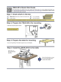
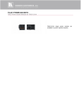
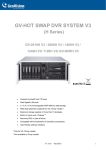
1
K R A ME R E LE CT R O N IC S L T D .
USER MANUAL
MODEL:
TBUS-201xl
Pop-up Table Connection Bus
P/N: 2900-300292 Rev 1
Contents
1
Introduction
1
2
2.1
2.1
Getting Started
Achieving the Best Performance
Recycling Kramer Products
2
2
3
3
Overview
4
4
4.1
4.2
Defining the TBUS-201xl
The TBUS-201xl Connecting Surface
Power Socket Options
5
6
7
5
5.1
5.2
5.3
5.4
6
Installing the TBUS-201xl
Cutting an Opening
Installing the Power Socket
Inserting the TBUS-201xl through the Cut-Out Opening
Connecting the Cables
Technical Specifications
8
8
10
11
11
12
Figures
Figure 1: TBUS-201xl Pop-up Table Connection Bus
Figure 2: Defining the Parts of the TBUS-201xl Pop-up Table Connection Bus
Figure 3: TBUS-201xl Connecting Surface
Figure 4: Cut out Dimensions (not to scale)
Figure 5: TBUS-201xl Universal Power Socket Housing
Figure 6: Power socket installed
4
5
6
9
10
10
TBUS-201xl – Contents
i
U
U
U
U
U
U
U
U
U
U
U
U
1
Introduction
Welcome to Kramer Electronics! Since 1981, Kramer Electronics has been
providing a world of unique, creative, and affordable solutions to the vast range of
problems that confront video, audio, presentation, and broadcasting professionals
on a daily basis. In recent years, we have redesigned and upgraded most of our
line, making the best even better!
Our 1,000-plus different models now appear in 11 groups that are clearly defined
by function: GROUP 1: Distribution Amplifiers; GROUP 2: Switchers and Routers;
GROUP 3: Control Systems; GROUP 4: Format/Standards Converters; GROUP 5:
Range Extenders and Repeaters; GROUP 6: Specialty AV Products; GROUP 7:
Scan Converters and Scalers; GROUP 8: Cables and Connectors; GROUP 9:
Room Connectivity; GROUP 10: Accessories and Rack Adapters and GROUP 11:
Sierra Video Products.
Thank you for purchasing the Kramer TBUS-201xl Pop-up Table Connection Bus,
which is ideal for boardrooms, conference and training rooms!
TBUS-201xl - Introduction
1
2
Getting Started
We recommend that you:
•
Unpack the equipment carefully and save the original box and packaging
materials for possible future shipment
•
i
2.1
Review the contents of this user manual
Go to http://www.kramerelectronics.com to check for up-to-date
user manuals, a complete list of Kramer wall plates and module
connectors, application programs, and to check if firmware
upgrades are available (where appropriate).
Achieving the Best Performance
To achieve the best performance:
•
Use only good quality connection cables (we recommend Kramer highperformance, high-resolution cables) to avoid interference, deterioration in
signal quality due to poor matching, and elevated noise levels (often
associated with low quality cables)
•
Do not secure the cables in tight bundles or roll the slack into tight coils
•
Avoid interference from neighboring electrical appliances that may adversely
influence signal quality
•
Position your Kramer TBUS-201xl away from moisture, excessive sunlight
and dust
!
This equipment is to be used only inside a building. It may only be
connected to other equipment that is installed inside a building.
Do not place heavy objects on top of the TBUS-201xl.
2
TBUS-201xl - Getting Started
2.1
Recycling Kramer Products
The Waste Electrical and Electronic Equipment (WEEE) Directive 2002/96/EC
aims to reduce the amount of WEEE sent for disposal to landfill or incineration by
requiring it to be collected and recycled. To comply with the WEEE Directive,
Kramer Electronics has made arrangements with the European Advanced
Recycling Network (EARN) and will cover any costs of treatment, recycling and
recovery of waste Kramer Electronics branded equipment on arrival at the EARN
facility. For details of Kramer’s recycling arrangements in your particular country
go to our recycling pages at http://www.kramerelectronics.com/support/recycling/.
TBUS-201xl - Getting Started
3
3
Overview
The TBUS-201xl is a furniture-mounted pop-up connection bus that is easily
installed into a table or podium top. The TBUS-201xl interface enables you to
connect any equipment to systems installed in a room via the following passthrough connectors:
•
1 PC on a 15-pin HD connector
•
1 HDMI connector
•
1 stereo audio on a 3.5mm connector
•
1 Ethernet RJ-45 connector
When not in use, you can lower the TBUS-201xl flush into the table. The example
in Figure 1 shows the TBUS-201xl in a table or podium top with a universal power
socket.
Figure 1: TBUS-201xl Pop-up Table Connection Bus
In addition, the TBUS-201xl is:
•
Easily opened and closed by pressing down gently on the lid due to its tilting
angular construction, pneumatic lift and mechanical latching mechanism. It
can be raised (when in use) or lowered (when not in use)
•
Suitable for any of the following power sockets: for the USA, the UK,
Germany (the Europlug), Belgium-France, Switzerland, Italy, Australia,
Brazil, Israel, South Africa or “Universal” for use anywhere (see compatibility
restrictions in Section 4.2)
Order the power sockets separately from Kramer Electronics
4
TBUS-201xl - Overview
4
Defining the TBUS-201xl
Figure 2: Defining the Parts of the TBUS-201xl Pop-up Table Connection Bus
1
#
Feature
Black anodized or brushed
anodized aluminum semiautomatic lid
2
Connecting Surface
See Section 4.1
3
Outer Rim
Fits over the table surface
4
Mini Latch
Enables the closing and opening of the lid by slightly
pressing it
5
Mounting Clamp Plates
For holding the clamps
6
Mounting Clamp Slits (four
sets on each side)
Insert the mounting clamps to the slits when installing the
TBUS-201xl
7
Rubber Protectors (2)
To ensure soft tightening to the table underside
8
Mounting Screws (2)
For securing the TBUS-201xl to the table
9
Locking Butterfly Nuts (2)
Tighten to lock the mounting butterfly screw
TBUS-201xl - Defining the TBUS-201xl
Function
Covers the connecting surface, leaving the table surface
neat and tidy
5
4.1
#
10
Feature
Mounting Butterfly Nuts (2)
Function
Tighten to secure the unit to the table surface
11
Mounting Clamps (2 units)
Place in the clamp slits after inserting the enclosure into
the table – for securing the unit to the table surface
12
Power Connector Lock
Secures the power cable so it does not accidently
disconnect when opening the lid
13
Pneumatic Piston
Enables automatic lifting and smooth closing of the lid
14
Power Socket Opening
Screw Holes (4)
For installing/replacing the power socket
The TBUS-201xl Connecting Surface
Figure 3 defines the connecting surface and includes the universal power socket
(sold separately) for illustration purposes only (note that although ‘TBUS-201’ is
printed on the panel, the name of the modular product is TBUS-201xl):
Figure 3: TBUS-201xl Connecting Surface
#
6
1
Feature
HDMI Connector
Function
Connect to an HDMI source
2
PC 15-pin HD Connector
Connect to a computer graphics source
3
AUDIO 3.5mm Mini Jack
Connects to an unbalanced stereo audio source
4
ETHERNET Connector
Connects to the PC or other Controller through computer
networking
5
Power Socket Opening
Suitable for various power sockets (see Section 4.2)
6
Connecting Surface
Pops up when gently pressing the lid
TBUS-201xl - Defining the TBUS-201xl
4.2
Power Socket Options
A choice of power sockets is available for purchase in several versions, including
power sockets for the USA, Brazil, Germany (the Europlug), UK, Switzerland,
Belgium-France, Italy, South Africa, Israel and Australia. A “Universal” socket for
general use is also available (see the compatibility restrictions in the table below).
Note that the photos below are for illustration purposes only.
Power Socket
Type
Universal:
Power Specs
Description
TS-201U (80-000043)
Fully compatible with power plugs in the
UK, India, Italy and Denmark, as well as
100-240V AC, 50/60Hz, 5A with the 2-prong Europlug.
Maximum 5A per power
outlet
Partially compatible (if the polarity is
reversed) with plugs in China, Switzerland,
Israel and the USA. The universal socket
does not supply grounding to plugs in Central
Europe and France and so you should order
country specific sockets instead.
Not compatible with South African plugs.
Power Socket
Type
USA:
Power Specs
Power
Socket Type
TS-201US (80-000046)
Italy:
100-125V AC, 50/60Hz, 5A
Maximum 5A per power
outlet
Germany and EU: TS-201DE (80-000044)
Belgium and
France:
South Africa
Switzerland
Power Specs
TS-201IT (80-000047)
100-240V AC, 50/60Hz, 5A
Maximum 5A per power
outlet
Australia:
TS-201AU (80-000050)
100-240V AC, 50/60Hz, 5A
100-240V AC, 50/60Hz, 5A
Maximum 5A per power
outlet
Maximum 5A per power
outlet
TS-201FR (80-000045)
Israel:
TS-201IL (80-000053)
100-240V AC, 50/60Hz, 5A
100-240V AC, 50/60Hz, 5A
Maximum 5A per power
outlet
Maximum 5A per power
outlet
TS-201ZA (80-000052)
Brazil
TS-201BR (80-000051)
100-240V AC, 50/60Hz, 5A
100-240V AC, 50/60Hz, 5A
Maximum 5A per power
outlet
Maximum 5A per power
outlet
TS-201CH (80-000049)
England
TS-201GB (80-000048)
100-240V AC, 50/60Hz, 5A
100-240V AC, 50/60Hz, 5A
Maximum 5A per power
outlet
Maximum 5A per power
outlet
TBUS-201xl - Defining the TBUS-201xl
7
5
Installing the TBUS-201xl
To install the TBUS-201xl perform the following steps:
1. Cut an opening in the table (see Section 5.1).
2. Install the power socket (see Section 5.2).
3. Insert the TBUS-201xl through the cut-out opening (see Section 5.3).
4. Connect the cables (see Section 5.4).
5.1
Cutting an Opening
The metal cutout template (supplied) defines the surface you have to cut out to
install your TBUS-201xl.
i
The thickness of the table should be 3in (76mm) or less.
To cut an opening in the table:
1. Before cutting the opening, confirm the dimensions of the cutout template
and make sure that they have not changed.
2. Place the included cut out template (that is included with your TBUS-201xl)
on the surface of the table exactly where you want to install the
TBUS-201xl.
3. Attach the template to the table with the included screws (if using the cut out
template).
4. Following the inside edge of the template, cut a hole in the table surface
with a sabre or keyhole saw according to the dimensions shown in Figure 4
(not to scale).
8
TBUS-201xl - Installing the TBUS-201xl
Figure 4: Cut out Dimensions (not to scale)
5. Unscrew and remove the template from the surface of the table and clean
the table surface.
Take care not to damage the table.
If needed, you can download a full-scale template from our Web site.
!
Kramer Electronics is not responsible for any damage caused to the
table.
TBUS-201xl - Installing the TBUS-201xl
9
5.2
Installing the Power Socket
Figure 5 shows an example of the Universal power socket housing which is one of
the optional power sockets for the TBUS-201xl, see Section 4.2.
Figure 5: TBUS-201xl Universal Power Socket Housing
To install the power socket:
1. Close the TBUS-201xl lid.
2. Carefully insert the power socket housing so that the power socket fits into
the power socket opening on the connecting surface and the four standoffs
fit the four screw holes on the TBUS-201xl.
When positioned correctly, the IEC socket faces downwards.
3. Screw the four screws included in the power socket kit into the designated
holes to fix the power socket housing in place (see Figure 6).
Figure 6: Power socket installed
4. Unscrew the power connector lock.
10
TBUS-201xl - Installing the TBUS-201xl
5. Connect the IEC power cord to the IEC socket.
6. Insert the power cord into the power connector lock and tighten the screw
(see Figure 2, item 12) to secure the power cable.
5.3
Inserting the TBUS-201xl through the Cut-Out Opening
To install the TBUS-201xl, do the following:
1. Carefully insert the unit into the prepared opening.
2. Take the support clamps under the table and place them into the support
clamp late slits at the desired height (on both the front and rear sides of the
unit).
3. Make sure that the upper outer rim is situated parallel to the edge of the
table.
4. Insert the mounting screws through the holes in the mounting clamps.
Tighten the mounting butterfly nuts to secure the unit to the table surface
and then lock with the mounting butterfly screw.
5.4
Connecting the Cables
1. Connect the appropriate cables from underneath.
2. Secure the cables.
Do not keep the cord too tight or too loose.
Once you have connected the unit to the mains power and connected the proper
cables, you may use the unit.
TBUS-201xl - Installing the TBUS-201xl
11
6
Technical Specifications
PORTS:
POWER SOURCE
(AC power limits):
1 HDMI connector, 1 Ethernet RJ-45 connector,
1 15-pin HD connector, 1 3.5mm mini jack
Power Socket Assemblies
Universal
100-240V AC, 50/60Hz, 5A
Maximum 5A per power outlet
Fully compatible with power plugs in the UK, India, Italy
and Denmark, as well as with the 2-prong Europlug.
Partially compatible (if the polarity is reversed) with
plugs in China, Switzerland, Israel and the USA. The
universal socket does not supply grounding to plugs in
Central Europe and France (you should order country
specific sockets instead).
Not compatible with South African plugs.
USA
100-240V AC, 50/60Hz, 5A
Maximum 5A per power outlet
Germany and EU
100-240V AC, 50/60Hz, 5A
Maximum 5A per power outlet
Belgium and France
100-240V AC, 50/60Hz, 5A
Maximum 5A per power outlet
Italy
100-240V AC, 50/60Hz, 5A
Maximum 5A per power outlet
Australia
100-240V AC, 50/60Hz, 5A
Maximum 5A per power outlet
Israel
220V AC, 50/60Hz, 5A
Maximum 5A per power outlet
FUSE RATING:
OPERATING TEMPERATURE RANGE:
OPERATING HUMIDITY RANGE:
STORAGE TEMPERATURE RANGE:
STORAGE HUMIDITY RANGE:
DIMENSIONS:
WEIGHT:
ACCESSORIES:
OPTIONS:
South Africa
220V AC, 50/60Hz, 5A
Switzerland
220V AC, 50/60Hz, 5A
England
220V AC, 50/60Hz, 5A
Brazil
220V AC, 50/60Hz, 5A
Maximum 5A per power outlet
Maximum 5A per power outlet
Maximum 5A per power outlet
Maximum 5A per power outlet
T 6.3A 250V
+5 to +45 Deg. Centigrade
10 to 90% RHL, non-condensing
-20 to +70Deg. C.
5 to 95% RHL, non-condensing
Including the outer rim: 14.5cm x 13.2cm x 17.3cm
(5.71" x 5.2" x 6.81") W, D, H
Without the outer rim: 13.3cm x 12.0cm x 17.3cm (5.24"
x 4.72" x 6.81") W, D, H
0.85kg (1.87lbs) approx.
1.2kg (2.65lbs) approx. with mounting brackets
1.4 kg (3.1lbs) approx. packed product
Cut out metal template
Power socket kits, power cord
Specifications are subject to change without notice at http://www.kramerelectronics.com
12
TBUS-201xl - Technical Specifications
For the latest information on our products and a list of Kramer distributors,
visit our Web site where updates to this user manual may be found.
We welcome your questions, comments, and feedback.
Web site: www.kramerelectronics.com
E-mail: [email protected]
!
SAFETY WARNING
Disconnect the unit from the power
supply before opening and servicing
P/N: 2900- 300292
Rev: 1