1
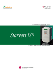
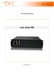
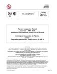
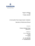
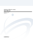
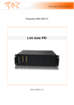
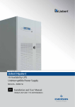
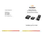
CAR-MAY USER MANUAL FOR MODEL NOVASYNC EIGHT CHANNEL SYSTEM Car-May LLC 308 Mountain View Rd. Berthoud, CO USA 513 P(970) 532-3997 F(970) 532-2817 www.car-may.com email: [email protected] Page 1 of 10 Revision 11/10/05 CAR-MAY Controller and channel one and two unit - Component Descriptions: 1. Display Touch Screen LCD display used for setting metering rate and displaying information to the user about pump status and control. 2. Touch Screen used for entering values and screen navigation. 3. Power entry module: power switch, fuse holder (with additional fuse) and plug for the included power supply cord. 4. The two nine pin connectors J1 and J2 are used for the RS-485 communication between the controller and the three satellite units (channels three through eight). 5. Round connector J3 (cannon 12-pin connector) –remote start function and connection to the satellite units (channels three though eight) CONTROLLER – FRONT VIEW CONTROLLER – REAR VIEW Page 2 of 10 Revision 11/10/05 CAR-MAY Installation and Setup: The only connections that need to be made to the Controller and satellites are the input AC power and control signals. The AC power is connected using the supplied power cords. The Controller and satellite signal cables are connected from the base station (blue enclosure) to each one of the satellite pump units in a daisy chain, using the three supplied nine pin RS-232/485 cables. Use the J1 connector located on the back of the base station. The arrangement of the nine pin serial cables is from the base station to the first satellite and then from the first satellite to the second and then from the second to the third satellite. The Agilent control connection between the pump panels and the other system components is done through the round cannon connectors. Use the supplied cable to connect the base station, each satellite and then to the Agilent 8543 system with the nine pin D-sub connector end of the cable. See the Agilent manual for connection of remote pumps start/stop and direction cable. Capabilities: The base station (Controller) is used to set and display the common metering rate for as many channels (up to eight pumps). The range is between the values of 0.5 ml/min to 20ml/min, with a resolution of .1 milliliters per minute. There are Enable and Disable function keys on the “Display Rate” screen. The keys are used to enable and disable remote control by the other components of the system e.g., the Agilent 8453 system. The remote system is used to start and stop the pumps and change the direction of rotation. Operation: Arrange the base station and satellites as shown in the picture on a flat surface and connect the power cords and signal cabling. Use the display screens and on screen buttons to set flow (metering) rates and channel offset values. In the individual screen descriptions buttons are shown in caps and bold print. The following are recommendations for getting the best performance and life out of the pumps. • • • • • Do not allow any particulates to enter the pump. The use of filters is strongly recommended if the product will produce particles. The use of filters is strongly recommended. Filter size will affect possible flow rates. Ten micron filters can be used for flow rate of up to 20 mls/min with tubing sets with no blockage. Tubing set size and total length will also determine possible flow rates. In general for 1/16” (0.062) OD x 1/32” (0.032) ID tubing flow rates should be less than 8-10 mls/min. For larger tubing the flow rate can be us to the maximum of 20 mls/min. The presence of bubbles forming in the suction side of the tubing can and usually is caused by cavitations of entrained gases in the liquid. To verify this slow the flow rate down by 50% If the bubble go away, they are caused by cavitation. Cleaning the tubing set or replacement is necessary. If the bubbles are still present check all fittings for air leakage. Contact Car-May for assistance if needed. Contact Car-May for replacement tubing sets and assistance. Bubbles on the return tubing set are caused by pump damage or loose fittings that allow air to enter T Page 3 of 10 Revision 11/10/05 CAR-MAY CONTROLLER – Main Screen This screen is used to choose either the Fluid Metering or the Offset Setup selection from the main screen. For operation choose the FLUID METERING button. For Offset Setup choose the OFFSET SETUP button. Offset setting and changing requires the user to have the password. CONTROLLER – METERING SETUP SCREEN If the Fluid Metering selection is chosen then the metering setup screen will be displayed as shown below. This screen is used to set a metering rate in milliliters per minute. Values can range from 0.5ml/min to 20.00ml/min. Select the rate amount by touching on the White box with the numbers. This will bring up a keypad which is used to enter the value. Once finished press the enter button. This will cause the enable/disable screen to be displayed. Page 4 of 10 Revision 11/10/05 CAR-MAY CONTROLLER – DISPLAY RATE SCREEN This screen displays the metering rate selected, number of pump channels connected and enable and disable functions. Enabling start and stop of the pump channels by remote systems is done from this screen. There are three buttons; ENABLE, DISABLE, and RETURN. During operation (when the program is running and the remote system has started the pump the pump channel icons on this screen will move showing that the pumps are turning. There should be a pump icon for each channel that the system has (four, six, and eight). If the channel icon is not present check the white signal cable is connected and not damaged. 1. The ENABLE button is used to start the metering program running and enable remote start and stop from the Agilent or other system. 2. The DISABLE button is used to stop the metering program from running and disable remote start and stop from the Agilent or other system. 3. The RETURN button is used to go back to the metering Setup screen or the Main screen (software version dependant) if a change in rate is desired. Page 5 of 10 Revision 11/10/05 CAR-MAY CONTROLLER – OFFSET SETUP PASSWORD SCREEN This screen displays the Password entry box, OFFSETS button, and RETURN button. It is used to enter the Offset Screen which allows the setting of individual channel offsets. Once the password is entered the user can go to either the Off Setup screen or return to the previous screen or the main screen (software version dependant). 1. To enter the password, touch the white screen. A keypad will popup and allow the user to enter a password of five digits. The password is set at the factory and can’t be changed in the field. The password was included with the original manual as a inserted sheet. To obtain a lost password please contact Car-May. The serial numbers of the base station and satellites will be required to obtain the password. 2. The OFFSETS button will bring up the Offset setup screen 3. The RETURN button is used to go back to the Main screen. Page 6 of 10 Revision 11/10/05 CAR-MAY CONTROLLER – OFFSET SETUP SCREEN This screen displays the Offset Setup (Editor) screen. It is used to enter the Offset values by channel (one to eight). Each pump channel has a factor box located to the right of the text. The function of the Offset value factor is to adjust the output of the pump channel to compensate for partially blocked or kinked tubing, thus extending the life of the tubing set and keeping the actual flow range to the level selected by the user. The range of values is from zero (0) to thirty (30) in increments of one (1). An example of use would be: The user has selected a rate of 6 ml/min. Due to the tubing set conditions the actual flow rate on channel three, when measured, is only 5.4 ml/min or ten percent less. Setting the Factor for that channel to 10 will cause the servo motor to increase speed 10%. IT SHOULD BE NOTED THAT THE SETTING OF THE FACTOR LEVEL DOES NOT (IN MOST CASES) CAUSE A ONE TO ONE RELATIONSHIP IN OUTPUT VOLUME. This is due to the fluid dynamics of the tubing set not being a linear relationship between restriction and flow. A more complete explanation is beyond the scope of this manual, contact Car-may for more details. So some trial and error may be necessary to obtain the correct flow rate. In the example presented it might be necessary to set the factor to a range between 8 and 14. Once set the value remains constant as long as the tubing channel remains the same. 1. Touching any of the eight white screens will cause a keypad will popup and allow the user to enter a value between zero (0) and thirty (30) for that pump channel. 2. The ENTER button will cause the Main screen or the Controller Display Rate screen to be displayed (software version dependant). Page 7 of 10 Revision 11/10/05 CAR-MAY Plumbing: The input and output ports may be labeled with the symbols I and O on the top of the manifold, depending on date of manufacture. If not the left hand port is the inlet and the right hand port. The size is ¼-28 NFT. Most common bottom seal fittings can be used. Some systems are shipped with tubing harnesses. Assemble using instructions from system integrator. Please note that manifold adaptors and/or O-rings may be required to use certain harness assemblies. The tubing used shall be large enough for the desired flow rates. Pump Internal Volume: The internal volume is divided into three areas, the cylinder, input porting, and output porting. The cylinder has a nominal volume of 200ul, input porting is 294ul (as measured to bottom of input fitting) and output porting is 294ul (as measured to bottom of output fitting). Thus the total internal volume is 784ul. Dead volume is defined as fluid left in the pump after the dispense phase assuming no further input and equals 294ul. Validation: The base station and satellites are calibrated at the factory and no field calibration is required. Periodic validation of the flow rate selected OF THE SYSTEM (the system is defined at the suction cannulas, suction tubing, flow cell, return tubing and return cannulas) should be performed as regular intervals. The frequency of the validation will depend on usage, tubing set selection, media used, and product being tested. The end user is responsible for determining the frequency. Contact Car-May for assistance if required. The frequency should be at least bi-annually if the system is in service and done before putting system into service. Car-May recommended validation procedure: Gravimetric method: 1. Use a pre-tared vessels (one for each channel). Use distilled, or RO water only. 2. New filters if suction cannulas are equipped with filter holders. 3. Meter or run the pump channels into each vessel for three minutes, and weight the result and subtract the tare value to obtain the flow rate for three minutes. Divide by three to obtain the flow rate per minute. Volumetric method: 1. 2. 3. 4. 5. Use eight small graduated cylinders of 25 milliliters or less . Use distilled, RO or WFI water only. New filters if suction cannulas are equipped with filter holders. Meter or run the pump channels into each vessel for three minutes, or at least one minute. Examine each cylinder to verify the flow rate is correct Maintenance: There are no recommended maintenance procedures for the Controller and satellites. The Controller and satellites can be cleaned with a damp cloth and a mild soap if required. Contact Car-May LLC for details. Pump module replacement can be done by trained personnel with a special tool and replacement modules supplied by Car-May LLC. Contact Car-May for assistance. Specifications: Metering Range 0.5 to 20.00ml/min Metering Resolution (Controller) .01ml/min Altitude Maximum 12000 feet Weight: 1kg per unit Operating Temperature 5 to 40o C Input Voltage 100 to 264 VAC, 4763hz, 380VA Maximum Storage Temperature –10 to 60o C when dry (not solution in pumps) Humidity 0 to 90% Non-condensing Page 8 of 10 Revision 11/10/05 CAR-MAY Page 9 of 10 Revision 11/10/05 CAR-MAY RETURN MATERIAL AUTHORIZATION # ____________ IMPORTANT NOTE • ITEM RETURNED MUST HAVE THIS FORM COMPLETED • ATTACH MSDS TO THIS FORM; MSDS is required for all liquids except pure water. (OSHA “Right to Know” law-29CFR 1910.1200) Name of last liquid pumped: ________________________________________________ MSDS Provided: • YES NO SERIAL # ________________________________ ENCLOSE FORMS IN AN ENVELOPE, SECURELY ATTACHED TO THE OUTSIDE OF SHIPPING CONTAINER IN AN EASILY-VISIBLE LOCATION I certify that the enclosed item(s) have been properly decontaminated and the appropriate MSDS is enclosed. I understand and agree that Car-May may bill my Company $500 as a decontamination fee if contaminants are discovered. Company:_______________________________________________________ Customer Name: ___________________________ Date: _________________ Authorized Signature: ______________________________________________ Phone #: _______________ Fax #: ________________ E-mail address: __________________ Return Item, Freight Prepaid to: : Car-May LLC. 308 Mountain View Rd. Unit D Berthoud, CO, USA 80513 RMA # ____________ To aid us in understanding your liquid handling needs, please fill in the blanks below: Page 10 of 10 Revision 11/10/05