1
and they appear to be much brighter so this makes sense.
Lighting is always a critical issue with any microscope. This model is being marketed as a medical
device for personal health. You are supposed to press the nose of the microscope against the skin to see
various skin conditions such as sores, ingrown hairs, blemishes, and skin damage - especially from the
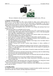
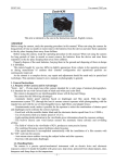
sun. The microscope has a knurled ring (as shown in Fig. 1) just above the white stand which is used to
focus the image. The intended use is to be hand held. Hand holding a microscope is normally difficult
but in this particular application it works well because it is pressed against the skin which allows you to
hold it steady.
There are two buttons. The top button controls the
lighting. The first press turns on the white LEDs.
The second press turns off the white and turns on
the blue uv LEDs. The third press turns all LEDs
off. The video camera is always on.
The bottom button is a “shutter” switch that takes
the photo.
The white plastic stand that comes in the very fancy
box is intended to hold the microscope when not in
use. Its internal shape matches the tapered nose.
I have very little interest in the skin application and
I had more conventional technical applications in
mind for this model when I bought it. One of the
objectives I have in writing this article is to
stimulate ideas for applying low cost USB
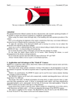
Fig. 2 – LEDs inside the camera with cover removed.
microscopes so the first applications “problem”
was to think of a way to use the uv hand held USB microscope in a more conventional way – not
handheld.
After a bit of thinking I had an idea. Why not drill a 3/4" hole in the
bottom of the stand and place the microscope stand on top of the
subject being examined? The microscope will be raised by 0.27.”
This turned out to be very practical and convenient. See Fig. 3. I
chose the hole size to be as large as possible and still insure that
there would be adequate (tapered) nose contact with the bottom of
the stand to provide holding friction when turning the microscope
against the forces of the significantly stiff cable.
The focusing range of the microscope easily covered the increased
Fig. 3 - 3/4” hole drilled in the stand.
(0.27”) distance. The first tests I made were to determine the
focusing range of the microscope and its viewable specimen size. See Fig 4.
Using the microscope in the stand is really convenient and it doesn’t involve buying, modifying, or
Page 2 of 11