1
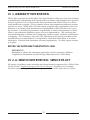
Manuals
French Version
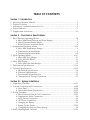
Service Manual
German Version
Spanish Version
Italian Version
SYSTO
LIC (m
m
Hg)
SpO2
%
TEMP
ERAT
URE
DIAS
TOLIC
(m
mHg)
Pulse
Tone
Volu
me
PULS
E (BPM
)
Sele
ct
Alarm
Chargi
ng
Low B
attery
CYC
LE
Set
Pow
er
Sta
rt
Can
cel
Rev
iew
Au
to
Sile
nce
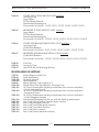
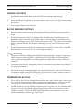
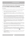
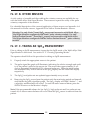
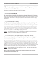
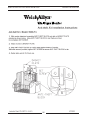
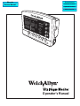
Operator’s Manual
CAUTION
United States Federal Law restricts this device to
sale by or on the order of a licensed health care practitioner.
TABLE OF CONTENTS
Section I - Introduction
1.
2.
3.
4.
5.
About the Operator Manual ..............................................................................................1
Product Overview ................................................................................................................1
Indications/Contraindications For Use ............................................................................2
Special Features ....................................................................................................................2
Supplies and Accessories ................................................................................................3-5
Section II - Functions & Specifications
1. Blood Pressure Operating Modes ..................................................................................7-8
a. Max/Min Blood Pressure and Pulse Ranges ......................................................7
b. Blood Pressure Manual Mode ................................................................................8
c. Blood Pressure Automatic Mode ..........................................................................8
2. Temperature Operating Modes ....................................................................................9-10
a. Max/Min Temperature Ranges..............................................................................9
b. Temperature Normal Mode ....................................................................................9
c. Temperature Monitor Mode..................................................................................10
3. SpO2 Operating Mode..................................................................................................10-11
a. Max/Min SpO2 Ranges ........................................................................................11
b. SpO2 Monitor Mode ..............................................................................................11
4. Pulse Rate Feature ..............................................................................................................12
a. Max/Min Pulse Rate Ranges................................................................................12
5. Performance Specifications..........................................................................................13-14
6. Technical Specifications................................................................................................14-15
a. Mechanical Specifications ....................................................................................14
b. Electrical Specifications ........................................................................................15
c. Environmental Specifications ..............................................................................15
d. Transportation/Storage Conditions ....................................................................15
Section III - System Installation
1. Unpacking Checklist ....................................................................................................16-17
2. Controls, Indicators and Connections........................................................................18-22
a. Front Panel ........................................................................................................18-20
b. Side & Rear Panel Connections ......................................................................21-22
3. Set Up Procedure ..........................................................................................................22-29
a. Blood Pressure Hose & Cuff Connections ....................................................22-23
b. Temperature Probe Connection ..........................................................................24
c. SpO2 Sensor Connection ......................................................................................25
d. AC Power Connection ..........................................................................................26
e. Charging the Battery ..............................................................................................26
f. Setting Up the Printer ......................................................................................27-28
g. Changing the Date and Time Setting ..................................................................29
4. Safety Warnings and Cautions....................................................................................30-32
WELCH ALLYN VITAL SIGNS MONITOR
OPERATOR MANUAL
Section IV - Operating Procedures
1. Power On/System Check Procedure ............................................................................34
2. Choosing Operating Modes..............................................................................................34
3. Setting the Programmable Alarms ............................................................................35-38
a. Blood Pressure - High Systolic Limit ..................................................................35
b. Blood Pressure - Low Systolic Limit ..................................................................36
c. Blood Pressure - High Diastolic Limit ................................................................36
d. Blood Pressure - Low Diastolic Limit ................................................................37
e. Pulse Rate - High Limit ........................................................................................37
f. Pulse Rate - Low Limit ..........................................................................................38
g. SpO2 - Low Limit ..................................................................................................38
4. Temperature Measurement Range Indicators ..............................................................39
5. Alarm Indications and Interpretation ............................................................................40
6. Setting the Default Inflation Pressure Preset Level......................................................41
7. Blood Pressure Cuff Selection Criteria ..........................................................................42
8. Positioning the Blood Pressure Cuff ..............................................................................43
9. Manual Mode Blood Pressure ........................................................................................43
10. Automatic Mode Blood Pressure ..............................................................................44-45
11. Reviewing Information from Prior Cycles ....................................................................46
a. “Erase Data” Function ..........................................................................................46
12. Selecting the Temperature Scale......................................................................................47
13. Selecting Temperature Operation Mode ........................................................................48
14. Taking Oral Temperature ............................................................................................49-50
15. Taking Axillary Temperature......................................................................................51-52
16. Taking Rectal Temperature ........................................................................................52-53
17. SpO2 Operation Mode ................................................................................................53-56
a. Using the Finger Clip Sensor................................................................................54
b. Other Sensors ..........................................................................................................55
c. Taking an SpO2 Measurement..............................................................................55
d. Using the SpO2 Pulse Tone ..................................................................................56
18. Printer Operation/Symbols ............................................................................................57
a. Printing Options: Batch Print or Streaming Print Mode ..................................58
19. Using the RS232 Computer Interface ............................................................................58
a. “Nurse Call” Interface ..........................................................................................58
20. Mean Arterial Pressure (MAP)/Data Send Mode/Data Stream Mode ....................59
Section V - Troubleshooting/Maintenance/Calibration
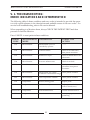
1. Troubleshooting: Error Indications and Interpretation ..........................................60-62
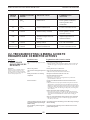
2. Troubleshooting: General Guide to Problems and Corrective Actions ................62-64
3. Maintenance ..................................................................................................................65-66
a. Cleaning ..................................................................................................................65
b. Storage ....................................................................................................................65
c. Battery Removal and Replacement......................................................................66
WELCH ALLYN VITAL SIGNS MONITOR
OPERATOR MANUAL
4. Calibration......................................................................................................................67-68
a. Blood Pressure Calibration Check..................................................................67-68
b. Temperature Calibration Check ..........................................................................68
c. SpO2 Calibration Check ........................................................................................68
Section VI - Warranty and Service Information
1. Warranty Information ........................................................................................................70
2. Service Information ......................................................................................................70-72
a. Service Policy ..........................................................................................................70
b. Technical Assistance/Service Centers............................................................71-72
c. Service Manual/Spare Parts ................................................................................72
d. Service Loaners ......................................................................................................72
Appendix
Appendix
Appendix
Appendix
A:
B:
C:
D:
Nonin® Brand SpO2 Sensors
Nellcor Puritan Bennett Brand SpO2 Sensors
Mounting Accessories & Assembly Instructions
Nurse Call Interface Wiring Diagram
TM
WELCH ALLYN VITAL SIGNS MONITOR
OPERATOR MANUAL
SECTION I
INTRODUCTION
1.
2.
3.
4.
5.
About the Operator Manual
Product Overview
Indications/Contraindications For Use
Special Features
Supplies and Accessories
WELCH ALLYN VITAL SIGNS MONITOR
OPERATOR MANUAL
I. 1 ABOUT THE OPERATOR MANUAL
The operator manual is designed to help you understand the capabilities and operation of
your Welch Allyn Vital Signs Monitor. The manual has six tabbed sections and the first
page of each section outlines the contents so you can readily find the information you need.
The information included in this manual is inclusive of all options available with the Welch
Allyn Vital Signs Monitor (ie. SpO2, Temperature and Printer). The applicability of some
sections of this operator manual will depend on the configuration of your particular unit.
The first two sections, INTRODUCTION and FUNCTIONS & SPECIFICATIONS introduce
you to the product, its applications and its capabilities. The next two sections, SYSTEM
INSTALLATION and OPERATING PROCEDURES takes you step by step through the
installation and functional operation of the monitor in a logical sequence. The final two
sections, TROUBLESHOOTING/MAINTENANCE/CALIBRATION and WARRANTY
AND SERVICE INFORMATION are resources to offer troubleshooting or other special
help as needed.
This information is intended as a comprehensive guide to the operation of the Welch
Allyn Vital Signs Monitor. To achieve satisfactory results, the operator should read this
manual thoroughly before attempting to use the monitor. A quick reference operator's
guide is provided on the side of the monitor as a convenient reference for experienced
operators.
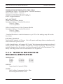
I. 2 PRODUCT OVERVIEW
The Welch Allyn Vital Signs Monitor is designed to non-invasively and automatically
measure systolic and diastolic blood pressure, pulse rate, temperature and oxygen saturation (SpO2) for adult and pediatric patients over the age of 3 years. All blood pressure,
pulse, temperature and SpO2 values are displayed on large, easy-to-read displays, and
may be printed via an integrated thermal printer, as desired.
The rechargeable battery and wide variety of mounting accessories make the Welch Allyn
Vital Signs Monitor convenient for many locations. The operator may choose any combination of simultaneous measurement modalities. This flexibility, combined with features
such as programmable alarms and automatic blood pressure cycles, makes the Welch
Allyn Vital Signs Monitor ideal for a wide variety of patient monitoring needs.
The Welch Allyn Vital Signs Monitor is intended for use in a wide variety of health care
settings. This includes hospital departments, as well as patient transport within the hospital environment. The Welch Allyn Vital Signs Monitor is also intended for use in alternate
care settings, such as physician offices, freestanding ambulatory care and surgery centers,
health clinics and nursing homes. The Welch Allyn Vital Signs Monitor may also be used
during patient transport within any of these alternate care environments.
The Welch Allyn Vital Signs Monitor is not intended for the monitoring of patients during
transport external to the health care environment (eg. ambulance, helicopter transport).
The Welch Allyn Vital Signs Monitor is not intended for use in environments which are
not supervised by a health care practitioner.
1
WELCH ALLYN VITAL SIGNS MONITOR
OPERATOR MANUAL
I. 3 INDICATIONS/CONTRAINDICATIONS FOR USE
The Welch Allyn Vital Signs Monitor is intended for monitoring of blood pressure, pulse
rate, temperature and oxygen saturation (SpO2) of adult and pediatric patients, age 3 and
above. The device is not designed, sold or intended for use except as indicated.
The monitor is not designed for use with neonates, infants or children under the age of 3
years.
The monitor should not be used on patients who are linked to heart/lung machines.
I. 4 SPECIAL FEATURES
The following special features enhance the use of the Welch Allyn Vital Signs Monitor:
Choice of Measurement Modalities
Non-invasive blood pressure, temperature, and SpO2 measurements may be made independently or simultaneously.
Operator Selectable BP Measurement Intervals
Automatically takes BP measurements at intervals from 1 to 90 minutes. Special "STAT"
mode allows continuous blood pressure measurements for up to 15 minutes.
Programmable Alarms
Both visual and audible alarms indicate readings outside of operator programmable
high/low limits, and also indicate system hardware/software problems.
Non-Invasive, Oscillometric BP
Eliminates the risks associated with invasive monitoring, with no need for microphones or
external transducers.
Prior Data Recall
Measurement data from up to 99 previous determinations is available at the touch of a
button.
Operator-Friendly Results
Large, easy-to-read LED displays are complemented by an integrated thermal printer.
AC or Self-Contained Battery Power
The Welch Allyn Vital Signs Monitor is conveniently available in many locations, for a
variety of monitoring needs, including interdepartmental transport within the facility.
2
WELCH ALLYN VITAL SIGNS MONITOR
OPERATOR MANUAL
I. 5 SUPPLIES AND ACCESSORIES
BLOOD PRESSURE ACCESSORIES AND SUPPLIES - LATEX FREE
5200-01
5200-02
5200-03
5200-10
Cuff Assembly:
Cuff Assembly:
Cuff Assembly:
Cuff Assembly:
Adult (cuff, bladder and connector)
Large Adult (cuff, bladder and connector)
Small (cuff, bladder and connector)
Extra-Large Adult (cuff, bladder and connector)
5082-59
5082-61
5082-63
5082-64
Cuff:
Cuff:
Cuff:
Cuff:
5200-04
5200-05
5200-06
5200-11
Bladder:
Bladder:
Bladder:
Bladder:
5200-07
5200-12
Coiled Pressure Hose (8ft.) (2.4M) Note: One additional hose may be
connected to provide extended length. All appropriate connectors are included.
Straight Pressure Hose (8ft.) (2.4M)
5200-08
Calibration T-Connector
Adult
Large Adult
Small
Extra-Large Adult
Adult (includes connector)
Large Adult (includes connector)
Small (includes connector)
Extra-Large Adult (includes connector)
TEMPERATURE ACCESSORIES AND SUPPLIES
5200-20
Oral Probe: (9ft.) (2.7M)
5200-22
Rectal Probe: (9ft) (2.7M)
05031-101
Disposable Probe Covers (1000 covers, packaged 25/box)
06137-000
Temperature Calibration Key
01800-210
Model 9600 Temperature Calibration Kit, 110v
NONIN® PULSE OXIMETRY ACCESSORIES AND SUPPLIES
5200-40
5200-54
5200-41
5200-42
5200-44
5200-45
5200-46
5200-47
5200-50
5200-51
5200-52
5200-53
5200-55
Finger Clip Sensor with 9ft. (2.7M) cable
Finger Clip Sensor with 3ft. (0.9M) cable
Ear Clip Sensor
Flex Sensor
Reflectance Sensor
Reflectance Sensor Holder (10)
SpO2 Adult Finger Flexiform Sensors (10)
SpO2 Pediatric Finger Flexiform Sensors (10)
SpO2 Sensor Attachment Tape
SpO2 Hydrogel Tape Strips
SpO2 Extension Cable (3ft) (0.9m)
SpO2 Finger Phantom Calibration Kit
SpO2 Extension Cable (9ft) (2.7m)
3
WELCH ALLYN VITAL SIGNS MONITOR
OPERATOR MANUAL
NELLCOR PURITAN BENNETTTM PULSE OXIMETRY ACCESSORIES
AND SUPPLIES
DS-lOOA DURASENSOR® Adult Oxygen Transducer
EC-8
Extension Cable (8 ft.)
D-YS
DURA-Y® Oxygen Transducer (1 sensor, 40 wraps)
D-YSE
Ear Clip, (use with Dura-Y sensor)
D-YSPD
PediCheckTM Pediatric Spot-Check (use with Dura-Y sensor)
D-25
OXISENSOR® II Adult Digit Oxygen Transducer (case of 24)
D-25L
OXISENSOR® II Adult Digit Oxygen Transducer, long cable (case of 24)
D-20
OXISENSOR® II Pediatric Oxygen Transducer (case of 24)
I-20
OXISENSOR® II Infant Digit Oxygen Transducer (case of 24)
R-15
OXISENSOR® Adult Nasal Oxygen Transducer (case of 24)
®
OXICLIQ A Adult Oxygen Transducer, use with OC-3 cable (case of 24)
OXICLIQ® P Pediatric Oxygen Transducer, use with OC-3 cable (case of 24)
OC-3
OXICLIQ® Sensor Cable
OXI-A/N
OXIBAND® Adult/Neonatal Oxygen Transducer (1 sensor, 50 wraps)
OXI-P/I
OXIBAND® Pediatric/Infant Oxygen Transducer (1 sensor, 50 wraps)
RS-10
Reflectance Oxygen Transducer (6 sensors, 6 headbands)
SRC-2
Portable Oximetry Tester
MOUNTING ACCESSORIES AND SUPPLIES
5200-60
COMPLETE MOBILE STAND UNIT includes:
Accessory Pack
Large Basket
Pole and Base Assembly
Transformer Mounting Kit
Recommended for Models: 52STP, 52STO, 52OTP, 52OTO, 52NTP, 52NTO
5200-61
MODIFIED MOBILE STAND UNIT includes:
Large Basket
Pole and Base Assembly
Transformer Mounting Kit
Recommended for Models: 52OOO, 52OOP, 52SOO, 52SOP, 52NOO, 52NOP
5200-62
COMPLETE WALL MOUNT UNIT includes
Accessory Pack
Large Basket
Wall Mount Bracket
Transformer Mounting Kit
Recommended for Models: 52STP, 52STO, 52OTP, 52OTO, 52NTP, 52NTO
5200-63
MODIFIED WALL MOUNT UNIT includes:
Large Basket
Wall Mount Bracket
Transformer Mounting Kit
Recommended for Models: 52OOO, 52OOP, 52SOO, 52SOP, 52NOO, 52NOP
4
WELCH ALLYN VITAL SIGNS MONITOR
OPERATOR MANUAL
5200-64
COMPLETE IV POLE MOUNT UNIT includes:
Accessory Pack
Large Basket
IV Pole Mount Bracket
Transformer Mounting Kit
Recommended for Models: 52STP, 52STO, 52OTP, 52OTO, 52NTP, 52NTO
5200-65
MODIFIED IV POLE MOUNT UNIT includes:
Large Basket
IV Pole Mount Bracket
Transformer Mounting Kit
Recommended for Models: 52OOO, 52OOP, 52SOO, 52SOP, 52NOO, 52NOP
5200-66
COMPLETE BED-RAIL MOUNTING UNIT includes:
Accessory Pack
(2) Bed-Rail Brackets
Recommended for Models: 52STP, 52STO, 52OTP, 52OTO, 52NTP, 52NTO
5200-67
MODIFIED BED-RAIL MOUNTING UNIT includes:
(2) Bed-Rail Brackets
Recommended for Models: 52OOO, 52OOP, 52SOO, 52SOP, 52NOO, 52NOP
5200-68
5200-69
5200-70
Cuff Clip
Accessory Pack
Anti-Theft Kit for Mounting Devices
MISCELLANEOUS SUPPLIES
7052-25
5200-84
5200-85E
5200-86E
5200-88
5200-100
5200-101
5200-102
5200-103
5200-106
5200-110
5200-111
5200-112
5200-113
5200-114
5200-115
Printer Paper (6 rolls/box)
Lead-acid Battery
Operator Manual
Service Manual
Plastic Monitor Covers (pack of 5)
Welch Allyn Vital Signs Monitor Carrying Case
AC Power Transformer (desktop transformer, line cord not included)
- North AmericanVersion
AC Power Transformer (desktop transformer, line cord not included)
- European Version
AC Power Transformer (desktop transformer, line cord not included)
- United Kingdom Version
Transformer Mounting Kit (for use with the desktop transformer)
Line Cord (United States/Canada/Japan version)
Line Cord (European version)
Line Cord (United Kingdom version)
Line Cord (Australian version)
Line Cord (Swiss version)
Line Cord (South American version)
5
WELCH ALLYN VITAL SIGNS MONITOR
OPERATOR MANUAL
SECTION II
FUNCTIONS AND SPECIFICATIONS
1. Blood Pressure Operating Modes
a. Max/Min Blood Pressure and Pulse Ranges
b. Blood Pressure Manual Mode
c. Blood Pressure Auto Mode
2. Temperature Operating Modes
a. Max/Min Temperature Ranges
b. Temperature Normal Mode
c. Temperature Monitor Mode
3. SpO2 Operating Mode
a. Max/Min SpO2 Ranges
b. SpO2 Monitor Mode
4. Pulse Rate Feature
a. Max/Min Pulse Rate Ranges
5. Performance Specifications
6. Technical Specifications
a. Mechanical Specifications
b. Electrical Specifications
c. Environmental Specifications
d. Transportation/Storage Conditions
6
WELCH ALLYN VITAL SIGNS MONITOR
OPERATOR MANUAL
II. 1. BLOOD PRESSURE OPERATING MODES
When a blood pressure measurement cycle is initiated, the cuff will automatically inflate
to the default pressure level.
The cuff will immediately begin to deflate in a stepped fashion and will determine systolic
pressure and diastolic pressure from the pulses sensed by the cuff at various pressure levels. This is the oscillometric method of non-invasive blood pressure monitoring.
Blood pressure measurements may be initiated manually, or automatically at time intervals determined by the user.
At the completion of a measurement cycle the systolic and diastolic pressures are displayed. If the Monitor is in Automatic Mode, the measured values are kept on display
until the next BP measurement is initiated. When not in Automatic Mode, the measured
values are displayed for two minutes, after which time the display screen is blanked. The
most recent BP measurement may be recalled by pressing the REVIEW button.
When in Automatic Mode, if the unit is unable to determine the systolic or diastolic
value, the measurement will be automatically repeated once.
II. 1. A. MAX/MIN BLOOD PRESSURE RANGES
The maximum and minimum ranges of blood pressure are detailed below:
Measurement
Maximum
Minimum
Systolic Pressure
250 mmHg
60 mmHg
Diastolic Pressure
160 mmHg
30 mmHg
7
WELCH ALLYN VITAL SIGNS MONITOR
OPERATOR MANUAL
II. 1. B. BLOOD PRESSURE MANUAL MODE
In the Manual Mode, a single blood pressure determination is made only when the START
button is pushed. The manual mode is the default mode of operation for blood pressure
determinations.
A measurement cycle may be cancelled at any time by pressing the CANCEL button. This
action immediately initiates a rapid cuff deflation.
The blood pressure measurement data will appear on the display immediately following
the measurement. The display will blank after two minutes. If the display is blanked,
pressing the REVIEW button on the front panel will recall the measurement. Up to 99
prior measurements are available for review or printing.
In Blood Pressure Manual Mode, the following alarm limits may be activated; SYSTOLIC
HIGH LIMIT, SYSTOLIC LOW LIMIT, DIASTOLIC HIGH LIMIT, DIASTOLIC LOW
LIMIT, PULSE RATE HIGH LIMIT and PULSE RATE LOW LIMIT. Blood pressure determinations which activate alarms are indicated by flashing displays and a repetitive audible tone. If an alarm limit is violated, subsequent blood presssure determinations may be
made only after the alarm condition is reset by pressing any button on the Monitor's display.
II. 1. C. BLOOD PRESSURE AUTOMATIC MODE
The Automatic Blood Pressure Mode is entered by pressing the AUTO button. Pressing
the AUTO button displays a choice of 11 cycle interval times as follows: "St" (STAT mode),
1 minute, 3 minutes, 4 minutes, 5 minutes, 10 minutes, 15 minutes, 30 minutes, 45 minutes, 60 minutes and 90 minutes. These choices represent the time interval from the
beginning of one cycle to the beginning of the next automatic cycle. STAT mode allows
the monitor to take continuous blood pressure measurements for 15 minutes. In addition,
the operator may choose to disable the Auto Mode by choosing "--" (two dashes).
Note: In the 1-minute automatic cycle mode, the Welch Allyn Vital Signs Monitor will
automatically take blood pressure measurements in 1-minute intervals for up to 15 minutes.
A measurement cycle may be cancelled at any time by pressing the CANCEL button. This
action immediately initiates a rapid cuff deflation.
The blood pressure measurement data will appear on the display immediately following
the measurement and will remain displayed until the next measurement cycle is initiated.
In Blood Pressure Auto Mode, the following alarm limits may be activated; SYSTOLIC
HIGH LIMIT, SYSTOLIC LOW LIMIT, DIASTOLIC HIGH LIMIT, DIASTOLIC LOW
LIMIT, PULSE RATE HIGH LIMIT and PULSE RATE LOW LIMIT. Blood pressure determinations which activate alarms are indicated by flashing displays and a repetitive audible tone. Any alarm limit violation must be reset to continue automatically timed blood
pressure determinations. The alarm may be reset by pressing any button on the Monitor's
display.
8
WELCH ALLYN VITAL SIGNS MONITOR
OPERATOR MANUAL
II. 2. TEMPERATURE OPERATING MODES
Thermometry measurements are made with the integrated Welch Allyn SureTemp® thermometer. Oral and rectal probes utilize single-use disposable probe covers which limit
cross-contamination. Oral, axillary or rectal temperatures are taken using 'Normal' or
'Monitor' operating modes. Axillary temperatures are taken using the oral probe.
In Normal Mode the thermometer's microprocessor "predicts" body temperature in about
4 seconds for oral temperatures, about 10 seconds for axillary temperatures and in about
15 seconds for rectal temperatures. The Monitor Mode displays the patient's actual temperature after 3 minutes and will continue to display an updated temperature as long as
the probe remains in place.
Note: Normal mode axillary temperatures (10 seconds) are accurate only for children
under the age of four.
Note: The Welch Allyn Vital Signs Monitor is intended for use with adult and pediatric
patients, age 3 and above.
Temperature readings may be displayed in Fahrenheit or Celsius scales.
II. 2. A. MAX/MIN TEMPERATURE RANGES
Measurement
Maximum
Minimum
Temperature, °F
Temperature, °C
108.0°F
42.2°C
84.0°F
28.9°C
II. 2. B. TEMPERATURE NORMAL MODE
In Normal Mode, the device will measure temperature at discrete intervals and then calculate the rate of change according to a proven algorithm. This allows the thermometer to
predict the end point that the thermistor would reach if it were left in the mouth until it
reached mouth temperature. This predictive feature allows the thermometer to arrive at
an accurate oral temperature reading in approximately 4 seconds.
Normal mode is the default operating mode for temperature determinations.
Operator selectable patient alarm limits are not available in Temperature Normal Mode.
However, temperatures which are outside of the operating range of the device will be
noted on the temperature display.
9
WELCH ALLYN VITAL SIGNS MONITOR
OPERATOR MANUAL
II. 2. C. TEMPERATURE MONITOR MODE
Continuous Monitor Mode operation is normally used for longer term monitoring and
when difficult situations prevent accurate temperatures from being taken in the normal
mode. The probe must be in contact with tissue for at least three (3) minutes for accurate
temperature measurement. Monitor mode temperatures may not be identical to predicted
'Normal' temperatures because of ambient temperature influence and other factors. The
trend in temperature is the important standard to be observed when in the Monitor mode.
Operator selectable patient alarm limits are not available in temperature monitor mode.
However, temperatures which are outside of the normal operating range of the device will
be noted on the temperature display.
II. 3. SpO2 OPERATING MODE
The Welch Allyn Vital Signs Monitor incorporates either the Nonin® or Nellcor Puritan
BennettTM pulse oximetry module which determines arterial oxyhemoglobin saturation
(SpO2%) by measuring the absorption of red and infrared light passed through the tissues.
Changes in absorption caused by pulsation of blood in the vascular bed are used to determine arterial saturation and pulse rate.
Oxygen saturation percent is calculated with each pulse detected, and thus the monitor
display is continually updated. The pulse signal bar graph is an indicator of the strength
and quality of the detected pulses.
When SpO2 is measured, the patient's pulse rate is also measured and displayed. A pulse
rate measurement from the SpO2 determination overrides a pulse rate measurement
derived from a blood pressure measurement.
When measuring SpO2 the user may enable the SpO2 Pulse Tone feature. A short audible
tone is emitted with every patient heartbeat. The frequency of the tone is based on the
patient’s SpO2 level. The lower the frequency of the tone, the lower the patients SpO2 level.
In SpO2 monitoring mode, operator selectable alarm limits for low SpO2 % may be activated. A condition which violates the SpO2 low limit alarm is indicated by a flashing display and repetitive audible tone. Should a patient alarm condition for SpO2 or pulse rate
occur, the Monitor will indicate an alarm condition (flashing & beeping) while continuing
to monitor and display the patient's current SpO2%. The alarm will automatically reset
when the patient's condition returns to within the preset alarm parameters.
Should a patient alarm condition for SpO2 or pulse rate occur, the operator may invoke
"Silence Mode" by pressing the SILENCE button. This will silence the audible tone (display will continue to flash), while the practitioner attends to the patient and the monitor.
Silence mode resets automatically after 30 seconds, or when the patient's condition returns
to within the preset alarm parameters.
10
WELCH ALLYN VITAL SIGNS MONITOR
OPERATOR MANUAL
Removal of the SpO2 sensor from the patient will initiate an alarm, unless the SpO2 and
pulse rate alarms are turned off. To reset the sensor alarm, press any button on the
Monitor's display.
SpO2 is generally measured via pulses detected using a finger sensor. However, for certain situations SpO2 may be measured at alternate sites including the earlobe, forehead
and toes. Special sensors must be employed in these situations.
II. 3. A. MAX/MIN SpO2 RANGES
The SpO2 sensor is designed to detect oxygen saturation as follows.
SpO2
Maximum
Minimum
99%
40%
II. 3. B. SpO2 MONITOR MODE
The SpO2 monitor performs most accurately with the fingerclip sensor, which may be
used on all fingers except the thumb. The finger clip sensor is recommended for spot
checks or short term continuous monitoring.
The device determines arterial oxyhemoglobin saturation (SpO2 %) by measuring the
absorption of red and infrared light passed through the tissue. Oxygen saturation and
pulse rate are displayed on the LED digital display. On each detected pulse, the pulse signal bar graph flashes. The intensity of this signal is a simple visual indicator of waveform
signal strength, and can identify situations where the pulsatile nature of the tissue may
not be adequate for an accurate SpO2 reading. The update interval of the bar graph
should correspond to the patient's pulse rate. This is an indication of the quality of the
SpO2 signal.
All Welch Allyn Vital Signs Monitors with pulse oximetry capability are equipped with a
pulse tone. This audible tone beeps in synchronization with each beat of the patient’s
heart. In addition, the frequency of the tone will vary based on the patient’s oxygen saturation value. The higher the tone’s frequency, the higher the patient’s oxygen saturation
value. The user may change the pulse tone volume, or turn this feature off as necessary.
11
WELCH ALLYN VITAL SIGNS MONITOR
OPERATOR MANUAL
II. 4. PULSE RATE FEATURE
The Welch Allyn Vital Signs Monitor is capable of determining pulse rate as an adjunct to
the blood pressure measurement and the SpO2 measurement.
The pulse rate, in beats per minute, will be determined primarily from the SpO2 measurement methodology. In the case where SpO2 is not available, or is disabled, the pulse rate
display will be driven by data from the blood pressure measurement method.
There are two operator selectable alarm limits for the pulse rate. They are PULSE RATE
HIGH LIMIT and PULSE RATE LOW LIMIT. Pulse rates which activate alarm limits are
indicated by a flashing display and a repetitive audible tone.
Should a pulse rate alarm occur when the pulse rate measurement is derived from the
blood pressure measurement, no subsequent blood pressure or pulse rate measurements
may be made until the alarm is reset. The alarm may be reset by pressing any button on
the Monitor's display.
Should a pulse rate alarm occur when the pulse rate measurement is derived from the
SpO2 measurement, the monitor will indicate an alarm condition (flashing & beeping)
while continuing to monitor and display the patient's current SpO2% and pulse rate. The
alarm will automatically reset when the patient's condition returns to within the preset
alarm parameters.
Should a patient alarm condition for pulse rate occur during SpO2 monitoring, the operator may invoke "Silence Mode" by pressing the SILENCE button. This will silence the
audible tone (display will continue to flash), while the practitioner attends to the patient
and Monitor. Silence mode resets automatically after 30 seconds, or when the patient's
condition returns to within the preset alarm parameters. If an alarm limit is violated, subsequent determinations of any type may only be made after the alarm condition is reset.
II. 4. A. MAX/MIN PULSE RATE RANGES
The maximum and minimum pulse rate ranges are as follows:
Pulse Rate
Maximum
200 bpm
12
Minimum
40 bpm
WELCH ALLYN VITAL SIGNS MONITOR
OPERATOR MANUAL
II. 5. PERFORMANCE SPECIFICATIONS
The performance specifications of the Welch Allyn Vital Signs Monitor are as follows:
CUFF PRESSURE RANGE
0 mmHg - 300mmHg
INITIAL CUFF INFLATION
Default cuff inflation pressure is 160 mmHg. Operator may change this default in
configuration mode. Options are 120, 140, 160, 180, 200, 240 and 280 mmHg.
SYSTOLIC DETERMINATION
Maximum: 250 mmHg
Minimum: 60 mmHg
DIASTOLIC DETERMINATION
Maximum: 160 mmHg
Minimum: 30 mmHg
BLOOD PRESSURE ACCURACY
Blood pressure accuracy meets or exceeds SP10-1992 AAMI standards for non-invasive
blood pressure accuracy (AAMI standard: ± 5 mmHg mean error; 8 mmHg standard
deviation). Blood pressure accuracy is validated for pressure measurement using the
upper arm only, with the patient in a seated position. Blood pressure is validated against
manual auscultatory readings.
BLOOD PRESSURE DETERMINATION TIME
20 seconds to 45 seconds typical, 165 seconds maximum.
PULSE RATE DETERMINATION
Maximum: 200 bpm
Minimum: 40 bpm
PULSE RATE ACCURACY
SpO2 Module Heart Rate (Nonin®)
SpO2 Module Heart Rate (Nellcor Puritan BennettTM)
Blood Pressure Algorithm Heart Rate
±3.0%
±3 bpm
±5.0%
OVERPRESSURE CUTOFF
295 mmHg to 330 mmHg
TEMPERATURE DETERMINATION
Normal and Monitor Modes: Maximum
Minimum
108.0°F (42.2°C)
84.0°F (28.9°C)
TEMPERATURE ACCURACY
Temperature accuracy meets ASTM E112-86: "Standard Specification for Electronic
Thermometer for Intermittent Determination of Patient Temperature."
13
WELCH ALLYN VITAL SIGNS MONITOR
OPERATOR MANUAL
TEMPERATURE DETERMINATION TIME (ORAL)
Normal Mode: ORAL: 4 seconds typical, 15 seconds maximum
Monitor Mode: ORAL: 3 minutes
OXYGEN SATURATION RANGE (SpO2%)
40-99% oxygen saturation
SpO2 ACCURACY
Nonin® Pulse Oximeter Module
Saturation (%SpO2 ± 1 Standard Deviation*)
70-99% ± 2 digits
< 70% unspecified
Nellcor Puritan BennettTM Pulse Oximeter Module
Saturation (%SpO2 ± 1 Standard Deviation*)
70-99% ± 3 digits
< 70% unspecified
* Standard Deviation is a statistical measure: up to 32% of the readings may fall outside
these limits.
BATTERY CHARGING
To at least 90% capacity in 12 hours. Unit will operate and charge battery simultaneously
when connected to power source.
A fully charged battery will support 200 "typical" blood pressure determinations taken at 3
minute intervals. Battery is 90-100% charged after 12 hours of charging. The battery automatically charges when the monitor is powered through the AC power transformer. The
battery will charge faster when the instrument is not in operation.
II. 6. A. TECHNICAL SPECIFICATIONS:
MECHANICAL SPECIFICATIONS
DIMENSIONS
Height
Length
Depth
6.5 inches
8.6 inches
5.0 inches
(16.5cm)
(21.8cm)
(12.7cm)
WEIGHT
Approximately 6 pounds (2.8Kg)
COLOR
Oral/Axillary Temperature Probe - Blue
Rectal Temperature Probe - Red
14
WELCH ALLYN VITAL SIGNS MONITOR
OPERATOR MANUAL
MOUNTING
Self-Supporting on rubber feet
IV Pole Mountable
Custom Mobile Stand
Wall Mountable
Attaches to Bed Rail
PORTABILITY
- May be hand carried when held by the recessed handle.
- When attached to an IV pole, or mounted on its custom mobile stand, the
monitor and accessories can be wheeled from patient to patient.
- When attached to the bed rail may be transported with the patient within the
hospital environment.
OPERATOR INSTRUCTIONS/ALARM INTERPRETATION
Comprehensive Operator Manual available. Quick reference operator instruction card
available.
II. 6. B. ELECTRICAL SPECIFICATIONS
POWER REQUIREMENTS
Patient-Rated isolation transformer is connected to AC mains power source:
North American Version: 120VAC, 60 Hz., 0.20A Input Source; 8Vdc, 0.75A Output Source
International Versions: 230VAC or 240VAC, 50Hz., 0.20A Input Source; 8Vdc, 0.75A Output Source
BATTERY
Lead acid, with external recharge capability.
II. 6. C. ENVIRONMENTAL SPECIFICATIONS
OPERATING TEMPERATURE
+10°C to +40°C
+50°F to +104°F
*Exception: Thermometry module will not maintain its performance
characteristics below 60°F (16°C).
OPERATING ALTITUDE
-170m to +4877m
-557ft. to +16,000ft.
II. 6. D. TRANSPORTATION/STORAGE CONDITIONS
STORAGE TEMPERATURE
-20°C to +50°C
-4°F to +122°F
RELATIVE HUMIDITY
15 to 90% (non-condensing)
15
WELCH ALLYN VITAL SIGNS MONITOR
OPERATOR MANUAL
SECTION III
SYSTEM INSTALLATION
1. Unpacking Checklist
2. Controls, Indicators and Connections
3. Set Up Procedure
a. Blood Pressure Hose & Cuff Connections
b. Temperature Probe Connection
c. SpO2 Sensor Connection
d. AC Power Connection
e. Charging the Battery
f. Setting Up the Printer
g. Changing the Time and Date Setting
4. Safety Warnings and Cautions
III. 1. UNPACKING CHECKLIST
After you have unpacked the Welch Allyn Vital Signs Monitor and the components, identify each item with the checklist that follows and inspect for missing items. Retain the
shipping materials in the event of shipping damage or for return, if necessary, to Welch
Allyn/Tycos for repair or warranty service.
All Welch Allyn Vital Signs Monitors include the following components (A-G):
A.
Welch Allyn Vital Signs Monitor
This device is a portable, light weight device designed to automatically measure
and display blood pressure and pulse rate. Options available include pulse oximetry, temperature and integrated printer.
B.
Operator Manual (This manual)
To achieve satisfactory results, the operator should read this manual thoroughly
before attempting to use the monitor. Save this manual for helpful product reference.
C.
Instrument Warranty Card
Fill this out today and return to Welch Allyn. This card validates your warranty.
16
WELCH ALLYN VITAL SIGNS MONITOR
D.
OPERATOR MANUAL
Large Adult Size Cuff Assembly
Includes cuff, bladder and pneumatic tubing with connector.
Note: A full range of cuff sizes are available (as accessory items) however, the
Large Adult cuff will fit the majority of adults and give the most accurate blood
pressure measurement.
E.
Coiled Pressure Hose
With connector, connects a variety of blood pressure cuffs to the monitor.
F.
Power Transformer and Cord Assembly
Operates the monitor and charges the internal battery.
G.
Cuff Clip
Attaches to the rear of the monitor to hold the blood pressure cuff. Not used if
mobile stand, pole mount or wall mount accessories are purchased.
Certain Welch Allyn Vital Signs Monitors will include the following items, based on the
options purchased:
PRINTER OPTION
H.
Box of Printer Paper
Six (6) rolls of thermal printer paper. One additional roll will be pre-loaded into the
printer.
PULSE OXIMETRY (SpO2) OPTION
I.
Finger Clip SpO2 Sensor and Cord
Other sensors are available separately.
TEMPERATURE OPTION
J.
Oral Temperature Probe
The blue oral probe is used for both oral and axillary temperature determinations.
A red rectal probe is available separately.
K.
Temperature Probe Covers
One box of 25 single use, disposable probe covers for both oral and rectal temperature determinations.
Note: Report any signs of shipping damage to the carrier. If an item is missing or damaged, contact the Welch Allyn Service Center near you. See section VI of this manual for
more information
17
WELCH ALLYN VITAL SIGNS MONITOR
OPERATOR MANUAL
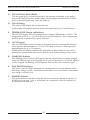
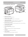
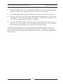
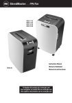
III. B. CONTROLS, INDICATORS AND CONNECTIONS
Note: In this section, all drawing and text are representative of the Welch Allyn Vital
Signs Monitor with all available options (i.e. Blood Pressure plus Pulse Oximetry (SpO2),
Temperature and Printer). Your Monitor may not include all functions, depending on the
options purchased.
P
N
M
R
S
I
Pulse
Tone
K
TEMPERATURE
SpO2 %
SYSTOLIC (mmHg)
J
Volume
G
Select
Alarm
Charging
L
DIASTOLIC (mmHg)
PULSE
Low Battery
(BPM)
CYCLE
H
Set
Q
T
O
Start
Power
A
B
Cancel
C
FRONT PANEL
Review
Auto
D
Silence
E
F
FRONT PANEL FUNCTIONS:
A.
POWER Button & Indicator Light
This on/off button controls the power to the Monitor. The indicator light will glow
when the unit is on. Battery power will be used unless the Monitor is powered
through the AC power transformer.
B.
START Button
Pressing this button initiates an on-demand blood pressure cycle.
C.
CANCEL Button
If a blood pressure cycle is in progress, pressing this button aborts the cycle and
immediately releases the cuff pressure. In "STAT" automatic blood pressure mode,
pressing the cancel button aborts the cycle in process, and cancels the "STAT" mode
as well.
When pressed for 3 seconds, the cancel button erases all stored data in the Welch
Allyn Vital Signs Monitor.
18
WELCH ALLYN VITAL SIGNS MONITOR
OPERATOR MANUAL
D.
REVIEW Button
Pressing this button will display the most current set of stored data including BP &
pulse rate and/or SpO2 and/or temperature. Subsequent presses will display the
next most recent data sets.
E.
AUTO Button & Indicator
Pressing this button allows the operator to scroll through the automatic blood pressure interval options. Time intervals are displayed in minutes on the CYCLE display
(see "Q" below). Choosing any time interval except "--" will cause the Auto indicator
light to glow, and blood pressure determinations to be made according to the displayed time interval.
F.
SILENCE Button & Indicator
During SpO2 monitoring, should an SpO2 or Pulse Rate alarm condition occur, pressing the Silence button invokes 'Silence Mode'. This will silence the audible tone (display will continue to flash), while the practitioner attends to the patient and Monitor.
Silence mode resets automatically after 30 seconds, or when the patient's condition
returns to within the preset alarm parameters. In Silence Mode, the silence indicator
light will glow.
G.
SELECT ALARM Button
Pressing this button allows the operator to select a specific parameter for which an
alarm threshold will be set. The HIGH ("HI") or LOW ("LO") indicator will show in
the CYCLE display, and the current value will appear in the respective display.
H.
SET Buttons (Arrow Up or Arrow Down)
These buttons increment or decrement the currently displayed alarm threshold.
The SET-Arrow Up button has additional functionality. See section IV.19.
I.
PULSE TONE Indicator
This indicator will be lit when the pulse tone function is enabled.
J.
PULSE TONE Button
Pressing this button allows the operator to control the volume of the SpO2 pulse tone.
K.
SYSTOLIC Display
This red LED display shows the systolic blood pressure.
Additionally, this display can show systolic alarm limits (see G, and H above).
L.
DIASTOLIC Display
This red LED display shows the diastolic blood pressure
Additionally, this display can show diastolic alarm limits (see G, and H above).
M.
SpO2 Display
This red LED display shows the percent saturation of arterial hemoglobin (SpO2%).
Additionally, this display can show SpO2 low saturation alarm limits
(see G, and H above).
19
WELCH ALLYN VITAL SIGNS MONITOR
OPERATOR MANUAL
N.
PULSE SIGNAL BAR GRAPH
This bar graph gives a visual indication of the strength and quality of the pulses
detected by the SpO2 sensor. Additionally, this bar graph can indicate the volume
level of the SpO2 pulse tone. (see I and J above).
O.
PULSE Display
This yellow LED display shows the pulse rate.
Additionally, this display can show pulse rate alarm limits (see G and H above).
P.
TEMPERATURE Display and Indicator
The red LED display shows the temperature in degrees Fahrenheit or Celsius. The
temperature scale (°F or °C) will be shown by a green indicator. Also, temperature
monitor mode is indicated by a green indicator.
Q.
CYCLE Display
This red LED display shows the time (in minutes) between automatically initiated
blood pressure measurements, or "St" for STAT mode (continuous blood pressure
measurements for up to 15 minutes).
Additionally, this display identifies the high and low alarm limits for the various
parameters, during alarm select mode, and the cycle number during review mode.
R.
CHARGING Indicator
This flashing yellow indicator will signify that the internal battery is being charged
when the Monitor is powered through the AC power transformer. When the Monitor
is fully charged, the flashing will be replaced with a solid yellow indicator light.
S.
LOW BATTERY Indicator
This yellow indicator light will remain on continuously as a visual indicator when
the battery charge is weak. The indicator will flash as a visual indicator that the battery charge is critically low.
T.
MEMORY Indicator
This green indicator will flash when the unit has reached its maximum capacity of
99 data sets in storage. Also, it will remain on continuously when the operator is
reviewing stored data sets.
20
WELCH ALLYN VITAL SIGNS MONITOR
OPERATOR MANUAL
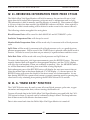
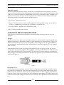
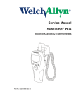
B. SIDE & REAR PANEL CONNECTIONS
8
9
4
7
1
5
2
11
10
6
3
1.
SpO2 Sensor Connection
Nine pin connector for the SpO2 sensor.
2.
Temperature Probe Connector
Connector for either oral/axillary (blue) or rectal (red) probe.
3.
Temperature Probe Holder
Active temperature probe is inserted here when not in use. Removing and
replacing the probe turns the temperature on and off, respectively.
4.
RS232 Data Interface Connector
Port for the connection of a cable to an external computer, network, or nurse call system.
5.
Transformer Power Connector
AC power transformer connector.
6.
Pressure Hose Connector
Connector for black, coiled pressure hose.
7.
Printer
Compartment and paper feed area for integrated thermal printer.
8.
Print Button
Pressing this button initiates a print operation.
9.
Printer Feed Button
Pressing this button advances the paper in the printer.
21
WELCH ALLYN VITAL SIGNS MONITOR
OPERATOR MANUAL
10.
Mounting Keyholes
Mounting accessories are attached via these keyholes.
11.
Battery Compartment
Contains the internal battery. Removal of 4 screws allows changing battery without
affecting other internal parts.
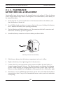
III. 3. A. SET-UP PROCEDURE:
BLOOD PRESSURE HOSE & CUFF CONNECTIONS
Identify and have available each of the following items:
-The Welch Allyn Vital Signs Monitor
-Cuff and bladder assembly
-Black coiled pressure hose
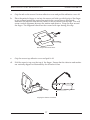
Using the illustrations below for reference, perform the following set-up procedures:
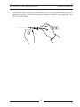
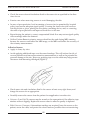
1.
Inspect the black coiled pressure hose and note that one end has a connector fitting
and the other end does not. Attach the end without the connector to the pressure
hose connector on the monitor by fitting the pressure hose on to the connector as
shown. Be sure that the pressure hose is completely inserted over the connector and
into the recess, and that the fit is snug.
Attaching pressure hose to connector on monitor
22
WELCH ALLYN VITAL SIGNS MONITOR
2.
OPERATOR MANUAL
Join the other end of the black coiled pressure hose to the pneumatic tubing which is
attached to the cuff. Twist the black plastic connectors together until finger-tight. DO
NOT OVER TIGHTEN.
23
WELCH ALLYN VITAL SIGNS MONITOR
OPERATOR MANUAL
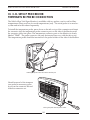
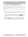
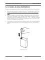
III. 3. B. SET-UP PROCEDURE:
TEMPERATURE PROBE CONNECTION
The Welch Allyn Vital Signs Monitor is available with two probes; one for oral/axillary
temperatures (blue), and one for rectal temperatures (red). The rectal probe is an accessory item and must be ordered separately.
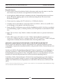
To install the temperature probe, press down on the tab on top of the connector and insert
the connector into the temperature probe connector port on the side of the Monitor until
the connector clicks into place. The temperature connector port on the Monitor is clearly
labeled "TEMP." The probe connector can only be inserted one way, with the tab on top.
The temperature probe should be inserted into the probe holder on the side of the Monitor.
Inserting the probe connector into the Monitor port
Should removal of the temperature probe be necessary, press
down on the connector tab and
slide the connector out.
SYSTO
LIC (m
mHg
)
SpO2
%
TEMP
ERAT
URE
DIAS
TOLIC
(m
mHg)
Pulse
Tone
Volum
e
PULS
E (BPM
)
Sele
ct
Alarm
Chargin
g
Low Ba
ttery
CYC
LE
Set
Pow
er
Sta
rt
Can
cel
Rev
iew
Au
to
Sile
nce
Placing the probe into the probe holder
24
WELCH ALLYN VITAL SIGNS MONITOR
OPERATOR MANUAL
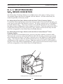
III. 3. C. SET-UP PROCEDURE:
SpO2 SENSOR CONNECTION
The Welch Allyn Vital Signs Monitor is available with a wide variety of SpO2 sensors.
The reusable finger clip sensor is shipped with the Monitor. All other sensors may be
ordered separately as accessory items.
For Welch Allyn Vital Signs Monitor with the Nonin® Pulse Oximetry Option:
To install the Nonin SpO2 sensor, insert the connector end of the sensor into the SpO2 connector port on the side of the Monitor as shown. The SpO2 connector port on the Monitor
is clearly labeled "SpO2." The sensor connector can only be inserted one way, matching
the shape and pin configuration of the connector to the port. Push the connector in until it
is fully seated on the port. Note: only Nonin® SpO2 sensors and accessories may be used
with this configuration of the Welch Allyn Vital Signs Monitor.
For Welch Allyn Vital Signs Monitor with the Nellcor Puritan BennettTM Pulse
Oximetry Option:
Attach the Nellcor Puritan Bennett SpO2 sensor to the pulse oximetry extension cable.
Then insert the connector end of the extension cable into the SpO2 connector port on the
side of the Monitor as shown. The SpO2 connector port on the Monitor is clearly labeled
“SpO2”. The extension cable can only be inserted one way; matching the shape and pin
configuration of the connector to the port. Push the connector in until it is fully seated on
the port. Note: Only Nellcor Puritan BennettTM SpO2 sensors and accessories may be used
with this configuration of the Welch Allyn Vital Signs Monitor.
Inserting the sensor connector into the Monitor port.
25
WELCH ALLYN VITAL SIGNS MONITOR
OPERATOR MANUAL
III. 3. D. SET-UP PROCEDURE:
AC POWER CONNECTION
The Welch Allyn Vital Signs Monitor may be powered by either AC power or battery
power after the battery has been charged.
To install the AC power transformer, insert the round transformer connector into the
power port on the side of the Monitor as shown. Insert the connector into the port until it
is fully seated. Insert the line cord into the line connector on the transformer.
Inserting the AC power transformer connector into the Monitor port
To power the Welch Allyn Vital Signs Monitor, plug the line cord into the AC mains
power source.
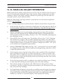
III. 3. E. SET-UP PROCEDURE:
CHARGING THE BATTERY
The Welch Allyn Vital Signs Monitor may be powered by either AC power or battery
power after the battery has been charged.
UPON INITIALLY RECEIVING THE MONITOR, CHARGE THE BATTERY FOR SIXTEEN (16) HOURS OR UNTIL THE CHARGING INDICATOR LIGHT NO LONGER
FLASHES. The battery is charged by attaching the AC power transformer to the Monitor,
and plugging the AC power transformer into the AC mains power source.
While charging, the charging indicator will flash a yellow light. When the Monitor is fully
charged the flashing light will be replaced with a solid yellow indicator light.
26
WELCH ALLYN VITAL SIGNS MONITOR
OPERATOR MANUAL
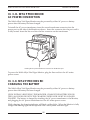
III. 3. F. SET-UP PROCEDURE:
SETTING UP THE PRINTER
A fully integrated thermal printer is available as an option to the Welch Allyn Vital Signs
Monitor.
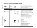
To load paper into the printer follow these steps:
1.
Grasp the printer cover as shown, and slide the cover off of the Monitor by sliding
the cover towards you.
Sliding off the printer cover
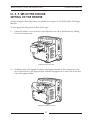
2.
Holding a new roll of paper as shown, feed approximately 1 inch of paper into the
slot at the bottom of the paper holder. Release the paper roll so that it sits in the bottom of the paper holder.
Feeding the paper into the slot
27
WELCH ALLYN VITAL SIGNS MONITOR
3.
OPERATOR MANUAL
Press the paper "FEED" button to advance the paper 3 to 4 inches above the top
paper slot.
Advancing the paper
4.
Thread the paper through the paper slot on the printer cover. Slide the cover on to
the Monitor and press down until it clicks into place as shown. The excess paper
may be torn off if desired.
Replacing the printer cover
Note: The operator will notice a red stripe along the edge of the printer paper when the
paper roll is almost at the end. Replace the printer paper with a new roll when the red
stripe is observed.
28
WELCH ALLYN VITAL SIGNS MONITOR
OPERATOR MANUAL
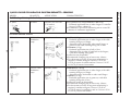
III. 3. G. SET-UP PROCEDURE:
CHANGING THE TIME / DATE SET
1
Initiate the Monitor's internal configuration settings menu by powering up the unit
while the START button is depressed. Hold the START button down until all the
LED display segments go off. The first message displayed is the revision level of the
internal software. This will be displayed in the systolic and diastolic displays.
2
Press the review button four (4) times to advance to the Date Set Screen. The year,
month and day will appear in the systolic, diastolic and heart rate displays respectively.
3
Use the SELECT ALARM button to select the date item to be changed. When selected, the date item will flash.
4
Use the SET buttons (arrow up or arrow down) to change the selected date item.
5
After making all the desired date changes, press the REVIEW button to save the
changes and advance to the Time Set Screen.
6
When in the Time Set Screen the hour (in 24 hour format) and minutes will appear in
the systolic and diastolic displays respectively. Use the SELECT ALARM and SET
buttons to set the time (in the same manner as described above).
7
When the time is set as desired, press the REVIEW button to save the time and
advance to the next screen.
8
Press the POWER button to turn the Monitor off.
29
WELCH ALLYN VITAL SIGNS MONITOR
OPERATOR MANUAL
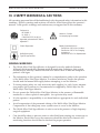
III. 4 SAFETY WARNINGS & CAUTIONS
All operating personnel should be familiarized with the general safety information in this
summary. Specific warnings and cautions will also be found throughout the operator's
manual. Such specific warnings and cautions may not appear here in this summary.
Conforms to
IEC 60601-1
UL 2601-1
CAN/CSA C22.2 No 601-1
Attention, Consult
Accompanying Document
Approved to Australia AS 3200.1,
Appendix Z
Class II Equipment
+
Defibrillator-proof,
Type BF Applied Part
Battery Operated Device
See Section 111.2.B for Location
See Section 111.3.E for Charging
Instructions
See Section V.3.C for Replacement
GENERAL WARNINGS
•
The Welch Allyn Vital Signs Monitor is designed for use by medical clinicians.
Although this manual may illustrate medical monitoring techniques, this system
should only be used by a trained clinician who knows how to take and interpret a
patient's vital signs.
•
The information in this operator's manual is a comprehensive guide to the operation
of the Welch Allyn Vital Signs Monitor. To achieve satisfactory results the operator
should read the manual thoroughly before attempting to use the Monitor.
•
To insure patient safety, use only accessories and supplies (i.e. cuffs, hoses, temperature probes, SpO2 sensors etc.) recommended or supplied by Welch Allyn for the
Welch Allyn Vital Signs Monitor.
•
Do not operate the Welch Allyn Vital Signs Monitor in the presence of flammable
anesthetics or other explosive atmosphere. An explosion may result.
•
It is the operator’s responsibility to set alarm limits as appropriate for each individual
patient.
•
Avoid compression of the pneumatic tubing of the Welch Allyn Vital Signs Monitor.
Compression of the tubing may cause system errors to occur in the Monitor.
•
The Welch Allyn Vital Signs Monitor is safe to use in the presence of high frequency
surgical equipment
•
Care should be taken to prevent water or other fluid from entering any connectors on
the Monitor. Should this occur, the connectors should be dried with warm air. All
monitoring functions should then be checked for proper operation.
30
WELCH ALLYN VITAL SIGNS MONITOR
OPERATOR MANUAL
•
Any Monitor which has been dropped or damaged should be checked by qualified
service personnel to insure proper operation prior to use.
•
Cords should periodically be checked for fraying or other damage, and replaced as
necessary.
•
There are no user serviceable parts inside the Monitor other than paper replacement
and battery replacement.
•
This Monitor is not designed for use with neonates, infants or children under the age
of 3 years.
•
This Monitor should not be used on patients who are linked to heart/lung machines.
•
This Monitor will not operate effectively on patients who are experiencing convulsions or tremors.
•
This device complies with current required standards for electromagnetic interference
and should not present problems to other equipment or be affected by other devices.
As a precaution, avoid using this device in close proximity to other equipment.
BLOOD PRESSURE WARNINGS
•
Blood pressure measurements may be inaccurate if cuffs and/or hoses are used other
than those provided for the Welch Allyn Vital Signs Monitor by Welch Allyn.
•
Blood pressure measurements may not be accurate for patients experiencing moderate to severe arrhythmias.
•
When monitoring over an extended period of time, or at frequent intervals, it is
recommended to check the cuff site and cuffed extremity regularly for possible
ischemia, purpura and/or neuropathy.
SpO2 WARNINGS
•
The operation of the SpO2 sensor in MRI environments is specifically not recommended.
•
Use only SpO2 sensors and accessories which are compatible with the SpO2 configuration purchased. Welch Allyn Vital Signs Monitor with the Nonin® pulse oximetry
option may only be used with Nonin® brand SpO2 sensors and accessories. Welch
Allyn Vital Signs Monitor with Nellcor Puritan BennettTM pulse oximetry option may
only be used with Nellcor Puritan BennettTM brand sensors and accessories.
TEMPERATURE WARNINGS
•
Single-use, disposable probe covers, available from Welch Allyn will limit patient
cross-contamination. The use of any other probe cover or the failure to use a probe
cover may produce temperature errors and is specifically not indicated.
•
Oral probes (blue) are to be used for taking oral and axillary temperatures only.
Rectal probes (red) are to be used for taking rectal temperatures only. The use of the
wrong probe may produce temperature errors.
31
WELCH ALLYN VITAL SIGNS MONITOR
OPERATOR MANUAL
GENERAL CAUTIONS
•
If the accuracy of any measurement is in question, check the patient's vital sign(s) by
an alternate method and then check the Monitor for proper functioning.
•
Insure the Monitor is placed on a secure surface or use one of the optional mounting
accessories.
•
Do not place fluids on the Monitor.
BLOOD PRESSURE CAUTIONS
•
Extremity and cuff motion should be minimized during blood pressure determinations.
•
If the blood pressure cuff is not at heart level, the difference in reading due to the
hydrostatic effect should be noted. The value of 1.80 mmHg must be added to the
displayed reading for every inch (2.5cm) above heart level. The value of 1.80 mmHg
must be subtracted from the displayed reading for every inch (2.5cm) below heart
level.
•
Proper blood pressure cuff size and placement is essential to the accuracy of the BP
determination. See Section IV.7 for cuff sizing information.
SpO2 CAUTIONS
•
The pulse oximeter is calibrated to determine the percentage of arterial oxygen saturation of functional hemoglobin. Significant levels of dysfunctional hemoglobins
such as carboxyhemoglobin or methemoglobin may affect the accuracy of the measurement.
•
Some intravascular dyes, depending on the concentration, may affect the accuracy of
the SpO2 measurement.
•
Some sensors may not be appropriate for a particular patient. If at least 10 seconds
of perfusion pulses cannot be observed for a given sensor, change sensor location or
sensor type until this condition is achieved.
TEMPERATURE CAUTIONS
•
Do not allow the tip of the temperature probe to come into contact with a heat source
(i.e. hands or fingers) prior to taking a temperature measurement. If this occurs discard the probe cover and start the temperature determination process again.
•
Normal Mode (10 second) axillary temperatures are accurate only for children under
the age of four. Normal Mode axillary temperatures will not be accurate on older
children or adults. The Welch Allyn Vital Signs Monitor is intended for use with
adult and pediatric patients, age 3 and above.
32
WELCH ALLYN VITAL SIGNS MONITOR
OPERATOR MANUAL
SECTION IV
OPERATING PROCEDURES
1. Power On/System Check Procedure
2. Choosing Operating Modes
3. Setting the Programmable Alarms
a. Blood Pressure - High Systolic Limit
b. Blood Pressure - Low Systolic Limit
c. Blood Pressure - High Diastolic Limit
d. Blood Pressure - Low Diastolic Limit
e. Pulse Rate - High Limit
f. Pulse Rate - Low Limit
g. SpO2 - Low Limit
4. Temperature Measurement Range Indicators
5. Alarm Indications and Interpretation
6. Setting the Default Inflation Pressure Preset Level
7. Blood Pressure Cuff Selection Criteria
8. Positioning the Blood Pressure Cuff
9. Manual Mode Blood Pressure
10. Automatic Mode Blood Pressure
11. Reviewing Information from Prior Cycles
12. Selecting the Temperature Scale
13. Selecting Temperature Operation Mode
14. Taking Oral Temperature
15. Taking Axillary Temperature
16. Taking Rectal Temperature
17. SpO2 Operation Mode
a. Using the Finger Clip Sensor
b. Other Sensors
c. Taking an SpO2 Measurement
d. Using the SpO2 Pulse Tone
18. Printer Operation/Symbols
a. Printing Options: Batch Print or Streaming Print Mode
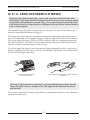
19. Using the RS232 Computer Interface
a. “Nurse Call” Interface
20. Mean Arterial Pressure (MAP)/Data Send Mode/Data Stream
Mode
33
WELCH ALLYN VITAL SIGNS MONITOR
OPERATOR MANUAL
IV.1. POWER ON/OFF AND SYSTEM CHECK PROCEDURE
Each time the Welch Allyn Vital Signs Monitor is turned on, the unit performs an internal
self-diagnostic check.
To turn the unit on, press the POWER button.
Upon power up, note that all of the LED segments in each display turn on briefly. An
audible tone should also sound. If the internal self-check is successful, the displays will
assume their normal functions and the monitor is ready for operation. If the self-check
fails, an error code will be shown in the displays.
To turn the unit off, press POWER button.
Note that turning the unit off will erase all stored blood pressure, temperature, SpO2 and
pulse rate data.
IV.2. CHOOSING OPERATING MODES
For all Welch Allyn Vital Signs Monitors which are configured with blood pressure and
pulse oximetry capability, the operator may choose to make either parameter non-functional. Having both blood pressure and pulse oximetry operational is the default operating mode. To make either mode non-functional, the user must enter the Monitor’s configuration mode. This may be accomplished by following these instructions:
• Turn the Monitor off.
• Press both the POWER button and the START button simultaneously. The Monitor will
enter it’s internal configuration mode.
• Press the REVIEW button 9 times. “ON” will appear in both the Systolic and SpO2
displays.
• Press the SET (arrow up and arrow down) buttons to cycle through the three options
available:
Systolic Display
On
SpO2 Display
On
Monitor Functionality
Both blood pressure and pulse oximetry
modes are operational. This is the factory
default mode.
OFF
On
Blood pressure mode is disabled. Pulse
oximetry mode is operational.
On
OF
Blood pressure mode is operational. Pulse
oximetry mode is disabled.
• When the desired functionality is displayed, press the REVIEW button once to save
this selection.
• Turn the Monitor off.
• When the Monitor is turned on, the new functionality setting will be established as the
default level. The Monitor will always revert to this setting on power up.
34
WELCH ALLYN VITAL SIGNS MONITOR
OPERATOR MANUAL
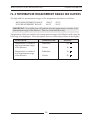
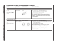
IV. 3. SETTING THE PROGRAMMABLE ALARMS
The Welch Allyn Vital Signs Monitor has the ability to generate a visual and audible alarm
when certain patient conditions are detected by the monitor. The following chart outlines
the conditions, ranges, programming intervals and default values for the alarm function.
Warning: It is the operator’s responsibility to set alarm limits as appropriate for each
individual patient.
Programmable
Alarm
Alarm
Ranges
Programmable
Intervals
Factory
Default Values*
BP - High Systolic
BP - Low Systolic
BP - High Diastolic
BP - Low Diastolic
Pulse Rate - High
Pulse Rate - Low
SpO2 - Low
245 - 65 mmHg
245 - 65 mmHg
35 - 155 mmHg
35 - 155 mmHg
45 - 195 bpm
45 - 195 bpm
98 - 70%O2
5 mmHg
5 mmHg
5 mmHg
5 mmHg
5 bpm
5 bpm
1%O2
200 mmHg
70 mmHg
155 mmHg
50 mmHg
140 bpm
45 bpm
85%
Note: Temperature default alarms are 108°F, 42.2°C (high) and 84.0°F, 28.9°C (low). The
temperature alarms are not programmable, they indicate that the patient's temperature
has exceeded the functional range of the thermometer.
*The unit will default to these factory settings only until the operator selects a different
alarm limit. When a new alarm limit is selected, the Monitor will retain this new limit setting in memory, even if the Monitor is turned off.
Alarm limits may be reviewed or changed by using the SELECT ALARM and SET (arrow
up and arrow down) buttons, and viewing the CYCLE display and the display of the
parameters being changed.
IV. 3. A. SETTING THE PROGRAMMABLE ALARMS:
BLOOD PRESSURE - HIGH SYSTOLIC LIMIT
Press the SELECT ALARM button until the SYSTOLIC display is illuminated, and the
CYCLE display shows "HI." This indicates the high systolic alarm setting.
The systolic display will show the current alarm limit for high systolic blood pressure in
mmHg or three dashes ("---") if the alarm is turned off. Pressing the SET (arrow up and
arrow down) buttons will cycle through the options in 5 mmHg intervals. The operator
may choose the high systolic blood pressure limit within the range of 245mmHg through
the current low systolic alarm limit. The alarm may be turned off by choosing "---."
When the desired alarm limit is displayed, pressing SELECT ALARM again saves the displayed alarm limit and changes the alarm parameter. Alternatively, pressing no buttons
for approximately 10 seconds will cause the displayed value to be set as the alarm limit,
and the Monitor will automatically revert to the current operating mode.
35
WELCH ALLYN VITAL SIGNS MONITOR
OPERATOR MANUAL
IV. 3. B. SETTING THE PROGRAMMABLE ALARMS:
BLOOD PRESSURE - LOW SYSTOLIC LIMIT
Press the SELECT ALARM button until the SYSTOLIC display is illuminated, and the
CYCLE display shows "LO." This indicates the low systolic alarm setting.
The Systolic display will show the current alarm limit for low systolic blood pressure in
mmHg, or "---" if the alarm is turned off. Pressing the SET (arrow up and arrow down)
buttons will cycle through the options in 5 mmHg intervals. The operator may choose the
low systolic blood pressure limit within the range of the current high systolic alarm limit
through 65mmHg. The alarm may be turned off by choosing "---."
When the desired alarm limit is displayed, pressing SELECT ALARM again saves the displayed alarm limit and changes the alarm parameter. Alternatively, pressing no buttons
for approximately 10 seconds will cause the displayed value to be set as the alarm limit,
and the Monitor will automatically revert to the current operating mode.
IV. 3. C. SETTING THE PROGRAMMABLE ALARMS:
BLOOD PRESSURE - HIGH DIASTOLIC LIMIT
Press the SELECT ALARM button until the DIASTOLIC display is illuminated, and the
CYCLE display shows "HI." This indicates the high diastolic alarm setting.
The diastolic display will show the current alarm limit for high diastolic blood pressure in
mmHg, or "---" if the alarm is turned off. Pressing the SET (arrow up and arrow down)
buttons will cycle through the options in 5 mmHg intervals. The operator may choose the
high diastolic blood pressure limit within the range of the current low diastolic limit
through 155mmHg. The alarm may be turned off my choosing "---."
When the desired alarm limit is displayed, pressing SELECT ALARM again saves the displayed alarm limit and changes the alarm parameter. Alternatively, pressing no buttons
for approximately 10 seconds will cause the displayed value to be set as the alarm limit,
and the Monitor will automatically revert to the current operating mode.
36
WELCH ALLYN VITAL SIGNS MONITOR
OPERATOR MANUAL
IV. 3. D. SETTING THE PROGRAMMABLE ALARMS:
BLOOD PRESSURE - LOW DIASTOLIC LIMIT
Press the SELECT ALARM button until the DIASTOLIC display is illuminated, and the
CYCLE display shows "LO." This indicates the low diastolic alarm setting.
The diastolic display will show the current alarm limit for low diastolic blood pressure in
mmHg, or "---" if the alarm is turned off. Pressing the SET (arrow up and arrow down)
buttons will cycle through the options in 5 mmHg intervals. The operator may choose the
low diastolic blood pressure limit within the range of 35mmHg through the current high
diastolic limit. The alarm may be turned off by choosing "---."
When the desired alarm limit is displayed, pressing SELECT ALARM gain saves the displayed alarm limit and changes the alarm parameter. Alternatively, pressing no buttons
for approximately 10 seconds will cause the displayed value to be set as the alarm limit,
and the Monitor will automatically revert to the current operating mode.
IV. 3. E. SETTING THE PROGRAMMABLE ALARMS:
PULSE RATE - HIGH LIMIT
Press the SELECT ALARM button until the PULSE display is illuminated, and the CYCLE
display shows "HI." This indicates the high pulse rate alarm setting.
The pulse display will show the current alarm limit for high pulse rate in bpm, or "---" if
the alarm is turned off. Pressing the SET (arrow up and arrow down) buttons will cycle
through the options in 5 bpm intervals. The operator may choose the high pulse rate limit
within the range of the current low pulse rate limit through 195bpm. The alarm may be
turned off by choosing "---."
When the desired alarm limit is displayed, pressing SELECT ALARM again saves the displayed alarm limit and changes the alarm parameter. Alternatively, pressing no buttons
for approximately 10 seconds will cause the displayed value to be set as the alarm limit,
and the Monitor will automatically revert to the current operating mode.
37
WELCH ALLYN VITAL SIGNS MONITOR
OPERATOR MANUAL
IV. 3. F. SETTING THE PROGRAMMABLE ALARMS:
PULSE RATE - LOW LIMIT
Press the SELECT ALARM button until the PULSE display is illuminated, and the CYCLE
display shows "LO." This indicates the low pulse rate alarm setting.
The pulse display will show the current alarm limit for low pulse rate in bpm, or "---" if
the alarm is turned off. Pressing the SET (arrow up and arrow down) buttons will cycle
through the options in 5 bpm intervals. The operator may choose the low pulse rate limit
within the range of 45bpm through the current high pulse rate alarm limit. The alarm
may be turned off by choosing "---."
When the desired alarm limit is displayed, pressing SELECT ALARM again saves the displayed alarm limit and changes the alarm parameter. Alternatively, pressing no buttons
for approximately 10 seconds will cause the displayed value to be set as the alarm limit,
and the Monitor will automatically revert to the current operating mode.
IV. 3. G. SETTING THE PROGRAMMABLE ALARMS:
SpO2 - LOW LIMIT
Press the SELECT ALARM button until the SpO2 display is illuminated, and the CYCLE
display shows "LO." This indicates the low SpO2 alarm setting.
The SpO2 display will show the current alarm limit for the SpO2% or "--" if the alarm is
turned off. Pressing the SET (arrow up and arrow down) buttons will cycle through the
options in 1% intervals. The operator may choose the low SpO2% limit within the range
of 98-70%, or the alarm may be turned off by choosing "--."
When the desired alarm limit is displayed, pressing SELECT ALARM again saves the displayed alarm limit and changes the alarm parameter. Alternatively, pressing no buttons
for approximately 10 seconds will cause the displayed value to be set as the alarm limit,
and the Monitor will automatically revert to the current operating mode.
38
WELCH ALLYN VITAL SIGNS MONITOR
OPERATOR MANUAL
IV. 4 TEMPERATURE MEASUREMENT RANGE INDICATORS
The high and low measurement ranges of the temperature module are as follows:
HIGH MEASUREMENT RANGE:
LOW MEASUREMENT RANGE:
108.0°F
84.0°F
42.2°C
28.9°C
IMPORTANT: No audible tone will indicate that the temperature is outside of the
measurement range of the Monitor. This is a visual indicator only.
Temperatures which are outside of the measurement range of the Monitor will cause the
following to be displayed. Note the symbol shown in the tenths position of the display.
CONDITION
TEMPERATURE
Temperature is outside of
high measurement range
of the Monitor.
Fahrenheit
108
Celsius
42
Temperature is outside of
low measurement range
of the Monitor.
Fahrenheit
84
Celsius
28
39
DISPLAY
WELCH ALLYN VITAL SIGNS MONITOR
OPERATOR MANUAL
IV. 5. ALARM INDICATIONS AND INTERPRETATION
Patient alarms will be activated when the patient's systolic pressure, diastolic pressure,
pulse rate or SpO2% exceed the alarm limits programmed by the operator. Patient alarm
conditions are visually indicated by flashing LED displays for the parameter in question,
accompanied by a repetitive audible alarm tone.
The Welch Allyn Vital Signs Monitor handles patient alarms in the following manner:
NOTE: Pulse rate measurements from the SpO2 determination override pulse rate measurements from the blood pressure determination.
DURING BLOOD PRESSURE MEASUREMENT:
Should a blood pressure or pulse rate patient alarm condition occur, no additional measurements may be initiated until the alarm is reset. Check the patient condition first, and
then reset the patient alarm by pressing the SILENCE button on the Monitor's display.
Measurements may now be resumed.
DURING SpO2 MEASUREMENT:
Should a patient alarm condition for SpO2 or pulse rate occur, the Monitor will indicate an
alarm condition (flashing & beeping) while continuing to monitor and display the
patient's current SpO2%. The alarm will automatically reset when the patient's condition
returns to within the preset alarm parameters.
DURING SpO2 MEASUREMENT:
Should a patient alarm condition for SpO2 or pulse rate occur, the operator may invoke
"Silence Mode" by pressing the SILENCE button. This will silence the audible tone (display will continue to flash), while the practitioner attends to the patient and Monitor.
Silence mode resets automatically after 30 seconds, or when the patient's condition returns
to within the preset alarm parameters.
Note: Certain alarms alert the operator to abnormal system conditions or internal system failures. Alarm conditions, error codes and suggested operator action are reviewed
in the Troubleshooting section (Section V.1.) of this manual.
40
WELCH ALLYN VITAL SIGNS MONITOR
OPERATOR MANUAL
IV. 6. SETTING THE DEFAULT INFLATION PRESSURE
PRESET LEVEL
The default cuff inflation level for blood pressure measurements is set in the Monitor’s
internal configuration menu. The factory default level is 160 mmHg. If desired, the default
pressure preset can be changed by following these instructions:
• Turn the monitor off.
• Press both the POWER button and the START button simultaneously. The Monitor will
enter it’s internal configuration mode.
• Press the REVIEW button 6 times. “PrP” will appear in the systolic display, and the
default pressure preset level will appear in the diastolic display.
• Press the SET (arrow up and arrow down) buttons to cycle through the seven options
available: 120, 140, 160, 180, 200, 240 and 280 mmHg.
• When the desired pressure preset level is illuminated, press the REVIEW button once to
save this change.
• Turn the Monitor off.
• When the Monitor is turned on, the new pressure preset will be established as the
default level. The Monitor will always revert to this pressure preset level, except in the
circumstances noted below.
Note: In Manual Blood Pressure Operating Mode, the Monitor will inflate to the default
pressure preset level. However, if a BP measurement is initiated within one minute of a
prior BP measurement, the Monitor will inflate to a level which is 40 mmHg above the
previous systolic reading.
In Automatic Blood Pressure Operating Mode, the Monitor will inflate to default pressure
preset level for the initial BP determination only. After the initial measurement, the
Monitor will inflate to a level which is 40 mmHg above the previous systolic reading.
IV. 7. BLOOD PRESSURE CUFF SELECTION CRITERIA
Note: A large Adult size cuff is included with your Vital Signs Monitor. A full range of cuff
sizes are available (as accessory items) however, the Large Adult cuff will fit the majority
of adults and give the most accurate blood pressure measurement.
Research has shown that an undersized cuff will overestimate the true blood pressure by
as much as 10 to 30 mmHg. Please refer to the reference markings located inside the cuff
for correct cuff sizing. When there is an area of overlap whereby you could use a smaller
or larger cuff, it is strongly recommended that you use the larger size cuff.
You may find that the bottom of the cuff extends to the antecubital fossa (bend in the
elbow) on many people, but because the Monitor uses oscillometric technology, not auscultation, this will NOT result in an inaccurate blood pressure.
Careful sizing of the cuff is important to the accuracy of blood pressure readings. If the
cuff is too small, the readings could be falsely high.
41
WELCH ALLYN VITAL SIGNS MONITOR
OPERATOR MANUAL
There are two simple methods for determining the correct cuff size for the patient. Use
either method (A) or (B) below.
(A) DETERMINING CUFF SIZE WITH THE CUFF MARKINGS
One way to insure proper cuff size is to wrap the cuff around the patient's upper arm
and visually check it. The cuff is marked with a distinct white edge and two divisions that indicate "range." When the cuff is properly fit, the edge will meet the cuff
at some point within the range. See illustration below.
(B) CHART FOR DETERMINING CUFF SIZE
You can also determine cuff size by measuring the patient's arm circumference midway between the elbow and shoulder, and then use the chart below to select the correct cuff.
➡
➡
RANGE
IND
EX
ADULT
➡
AR
TE
RY
31.5
cm
MA
XS
IZE
CUFF SIZE
ARM CIRCUMFERENCE
INCHES
CENTIMETERS
Small
4.7 - 8.3
12.0 - 21.0
Medium
7.1 - 12.6
18.0 - 32.0
Large
8.3 - 15.4
21.0 - 39.0
Extra-Large
11.8 - 18.5
30. - 48.0
42
WELCH ALLYN VITAL SIGNS MONITOR
OPERATOR MANUAL
IV. 8. POSITIONING THE BLOOD PRESSURE CUFF
The preferred blood pressure measurement site for adults and children is the upper arm.
The arm must be relaxed and motion-free during measurement(s).
Warning: Do not place the cuff on any extremity being used for intravenous infusions, or
any area where circulation is or may be compromised.
Warning: Do not place the cuff on any extremity being used for SpO2 monitoring. Cuff
inflation during an SpO2 measurement will cause inaccurate SpO2 results.
Wrap the cuff snugly with room between the cuff and the arm for two fingers. Excessive
tightness may cause venous congestion and discoloration of the limb. If the cuff is wrapped
too loosely, it cannot be inflated properly and the measured values may be in error.
It is best to place the cuff on a bare arm. Clothing may interfere with measurement accuracy.
When wrapping the cuff, observe the mark on the cuff which must be placed over the
artery. Insure that the hose is not twisted, kinked or compressed, as this may cause measurement errors.
IV. 9. MANUAL MODE BLOOD PRESSURE
Blood pressure measurement may be initiated on demand by the operator. This is the
manual mode of operation.
To operate the blood pressure monitor in manual mode, follow this procedure:
1.
Insure that the blood pressure cuff is properly sized and wrapped around the
patient's upper arm (or alternate site, as necessary).
2.
With the Monitor powered up, press the START button. The Monitor will inflate the
cuff to the default pressure preset level.
Note: If a BP measurement is initiated within one minute of a prior BP measurement, the
Monitor will inflate to a level which is 40 mmHg above the previous systolic reading.
3.
The systolic display will show the pressure in the cuff as the blood pressure determination is being made.
4.
When the measurement cycle is complete an audible tone will sound and the systolic,
diastolic and pulse rate* display will show the values of the reading.
5.
The reading will be displayed for two minutes, and then this display will be blanked.
The reading may be recalled at any time prior to the next BP determination by pressing the REVIEW button.
6.
Pressing CANCEL at any time during a blood pressure determination will cause the
determination to be aborted, and the cuff to rapidly deflate.
43
WELCH ALLYN VITAL SIGNS MONITOR
OPERATOR MANUAL
*Pulse rate, as determined from the blood pressure measurement method, will be displayed
with the BP reading only if SpO2 option is absent or disabled. If the SpO2 function is operational, all pulse rate determinations will come as a result of the SpO2 measurement method.
IV. 10. AUTOMATIC MODE BLOOD PRESSURE
Blood pressure measurements may be automatically initiated at operator programmed
time intervals.
To operate the blood pressure monitor in automatic ("Auto") mode, follow this procedure:
1.
Insure that the blood pressure cuff is properly sized and wrapped around the
patient's upper arm (or alternate site, as necessary).
2.
Press the AUTO button and note two dashes "--" in the CYCLE display. This is the
default setting for AUTO mode and indicates that no time interval cycles have been
selected.
3.
Select one of the ten pre-programmed cycle interval times by pressing the AUTO button until the desired interval time (in minutes) is displayed. The operator may
choose from the following time interval selections: 1, 3, 4, 5, 10, 15, 30, 45, 60 or 90
minutes. Note: These intervals represent the time from the beginning of one cycle to
the beginning of the next cycle. Note: In 1-minute automatic cycle mode, the Monitor
will automatically take BP measurements in 1 minute intervals for up to 15 minutes.
The operator may also choose "St", STAT mode. In STAT mode the Monitor takes
blood pressure readings repeatedly for up to 15 minutes. A new measurement cycle
will be initiated when the cuff pressure from the previous cycle drops below
10mmHg.
4.
When the desired interval is displayed, the operator may select the interval by pressing any other button or by refraining from pushing the AUTO button for 10 seconds.
When the interval is stored, the AUTO indicator light will glow green.
5.
The unit will take its first automatic blood pressure determination 10 seconds after
the time interval is selected. Subsequent readings will be taken according to the time
interval selected.
6.
For the first automatic blood pressure determination, the Monitor will inflate the cuff
to the default pressure preset level. For all subsequent blood pressure determinations, the Monitor will inflate the cuff to a pressure 40 mmHg above the prior systolic
reading.
7.
The systolic display will show the pressure in the cuff as the blood pressure determination is being made.
Exception: In STAT mode, the systolic and diastolic displays will show the most current
completed BP measurement.
44
WELCH ALLYN VITAL SIGNS MONITOR
OPERATOR MANUAL
8.
When the measurement cycle is complete an audible tone will sound and the systolic,
diastolic and pulse rate* displays will show the values of the reading.
9.
The measurement will be displayed until the next measurement cycle is initiated.
10.
Pressing CANCEL at any time during a blood pressure determination will cause the
determination to be aborted, and the cuff to deflate. In STAT mode, pressing CANCEL will also terminate the STAT mode of operation.
11.
To end an AUTO blood pressure session, press the AUTO button until two dashes "--"
appear in the CYCLE display. Auto mode will then be terminated. STAT mode may
be terminated in this manner, or by pressing the CANCEL button.
*Pulse rate, as determined from the blood pressure measurement method, will be displayed with the BP reading only if the SpO2 option is absent or disabled. If the SpO2
function is operational all pulse determinations will come as a result of the SpO2 measurement method.
45
WELCH ALLYN VITAL SIGNS MONITOR
OPERATOR MANUAL
IV. 11. REVIEWING INFORMATION FROM PRIOR CYCLES
The Welch Allyn Vital Signs Monitor will hold in memory the previous 99 sets of vital
signs data which include blood pressure, pulse rate and/or temperature and/or SpO2.
The information is held in memory until the Monitor is turned off. When memory capacity (99 sets of data) has been reached, the MEMORY indicator will blink. After capacity is
reached, the oldest stored reading will be deleted to make room for the newest data set.
The following criteria are applied for saving data:
Blood Pressure Data: will be saved for both MANUAL and AUTOMATIC cycles.
Predictive Temperature Data: will always be saved.
Monitor Mode Temperature Data: will be saved only if concurrent with a blood pressure
cycle.
SpO2 Data: will be saved if concurrent with a blood pressure cycle, or a predictive temperature measurement. Will be saved if the START button is pressed while the BP mode is
inactive. Will also be saved (one data set per minute) if a patient alarm condition occurs.
Pulse Rate Data: will be saved with every blood pressure and SpO2 data set.
To review data from prior vital signs measurements, press the REVIEW button. The most
recently obtained data will appear in the appropriate displays, and the CYCLE display
will show the total number of data sets currently in memory. Also, the MEMORY indicator will be illuminated, indicating that stored data is being displayed.
Each subsequent press of the REVIEW button will display the next most recent data set.
After the earliest data set has been displayed (CYCLE display = 1) the next press of the
REVIEW button will return the display to the most recent set of measurements. At any
time during REVIEW the operator may return to normal operating mode by pressing any
other button or by refraining from pressing the REVIEW button for 10 seconds.
IV. 11. A. “ERASE DATA” FUNCTION
The CANCEL button may be used to erase all stored blood pressure, pulse rate, oxygen
saturation and temperature data, without turning the Monitor off.
To erase all stored data in the Welch Allyn Vital Signs Monitor, press and hold the CANCEL button for three (3) seconds until a confirmatory beep is heard. This beep indicates
that all data stored in the Monitor has been erased.
Data is also erased each time the Welch Allyn Vital Signs Monitor is turned off.
46
WELCH ALLYN VITAL SIGNS MONITOR
OPERATOR MANUAL
IV. 12. SELECTING THE TEMPERATURE SCALE
The temperature module option of the Welch Allyn Vital Signs Monitor is capable of displaying temperature in either degrees Fahrenheit (°F) or degrees Celsius (°C).
To determine the current temperature scale, remove the temperature probe from its holder
and view the TEMPERATURE display. A small green display will illuminate showing
either "°F" or "°C."
To change the temperature scale, the user must enter the Monitor's internal configuration
mode:
1.
While the Monitor is turned off, press both the POWER and START buttons simultaneously. Hold the START button down until all of the LED display segments are illuminated.
2.
The operator can now cycle through the Monitor's internal configuration menu by
pressing the REVIEW button. Pressing the REVIEW button three times will cycle to
the temperature options and three dashes (---) will appear in the TEMPERATURE
display.
3.
The first option illuminated on the TEMPERATURE display is "°F." Pressing the
ADJUST button twice will illuminate "°C." When the desired temperature scale is
selected, press the REVIEW button again and then turn the Monitor off. By following this procedure, the selected temperature scale will be saved into memory.
47
WELCH ALLYN VITAL SIGNS MONITOR
OPERATOR MANUAL
IV. 13. SELECTING TEMPERATURE OPERATION MODE
When configured with the temperature option the Welch Allyn Vital Signs Monitor has the
capability of taking a temperature in either Normal or Monitor mode.
In the Normal mode the thermometer's microprocessor "predicts" body temperature in
about 4 seconds for oral temperatures, about 10 seconds for axillary temperatures and in
about 15 seconds for rectal temperatures.
Monitor mode is normally used for longer term monitoring and when difficult situations
prevent accurate temperature from being taken in the Normal mode. In Monitor mode,
the probe must be in contact with tissue for at least 3 minutes for accurate temperature
measurement.
Note: Normal mode axillary temperatures are only accurate on children 4 years or
younger.
Note: The Welch Allyn Vital Signs Monitor is intended for use with adult and pediatric
patients, age 3 and above.
The default setting for the Monitor is Normal mode.
To change the operating mode for temperature determinations, the user must enter the
Monitor's internal configuration mode:
1.
While the Monitor is turned off, press both the POWER and START buttons simultaneously. Hold the START button down until all of the LED display segments are
illuminated.
2.
The operator can now cycle through the Monitor's internal configuration menu by
pressing the REVIEW button. Pressing the REVIEW button three times will cycle to
the temperature options, and three dashes (---) will appear in the TEMPERATURE
display.
3.
Press the ADJUST button once to choose Monitor mode (°F), or three times to choose
Monitor mode (°C). When the desired selections are made, press the REVIEW button again and then turn the Monitor off. These choices will be saved into memory.
Note: If the temperature is in Normal mode, the user may easily switch to Monitor mode
without entering the Monitor's internal configuration mode. To do this, remove the probe
from the probe holder, attach a new probe cover, and wait one minute (do not place probe
in patients mouth, underarm or rectum at this time). After one minute the Monitor will
automatically switch to temperature Monitor mode, and the green "Monitor Mode" display will be illuminated on the temperature display. The operator may now proceed to
take the patient's temperature. After the probe is replaced in the holder, the Monitor will
revert back to Normal temperature mode.
48
WELCH ALLYN VITAL SIGNS MONITOR
OPERATOR MANUAL
IV. 14. TAKING AN ORAL TEMPERATURE
To take an oral temperature (in either Normal or Monitor mode) follow this procedure:
1.
Insure that the oral probe is connected to the unit. The oral probe has a BLUE tip.
Accurate oral temperatures can only be obtained by using the blue temperature
probe.
2.
Remove the probe from the probe holder. A short self-test mode will be initiated
where every LED segment on the TEMPERATURE display is illuminated briefly.
Following this self-test the display will show "OrL". "OrL" = Oral Probe indicating
that the oral probe is in use. The Monitor’s display must show “OrL” prior to the
initiation of a temperature measurement.
3.
Load a probe cover onto the probe by holding the probe collar with the thumb and
forefinger, being careful not to hold or press the ejection button. See illustration
below.
Loading the probe cover
49
WELCH ALLYN VITAL SIGNS MONITOR
4.
OPERATOR MANUAL
Insert the probe tip gently into the patient's slightly opened mouth. Carefully slide
the probe under the tongue on either side of the mouth to reach the sublingual pocket (see illustration below). Accurate temperatures can only be obtained in this location. Temperatures in other mouth locations can vary by as much as 2°F or 1°C.
Location of the sublingual pockets
5.
The probe should be held by the clinician during the entire temperature measurement process to insure the probe tip maintains tissue contact.
6.
During the temperature measurement cycle the TEMPERATURE display will show a
series of LED segments in a box - shaped formation. This indicates that the temperature measurement is in process.
7.
When the final temperature has been reached a tone will sound and the temperature
will be displayed on the Monitor.
8.
After the temperature measurement is complete, remove the probe from the patient's
mouth and eject the probe cover by firmly pressing the ejection button on the probe.
Properly dispose of the used probe cover.
9.
Insert the probe into the probe holder before attempting to take another temperature
measurement.
10.
The current temperature is displayed for one minute after the probe is replaced in the
holder, after which time the display will go blank. The most recent temperature can
be recalled by pressing the REVIEW button once.
Note: If a probe position error occurs during the temperature determination, the temperature display will alternate between the final predicted temperature and the letter "P" in the
display.
50
WELCH ALLYN VITAL SIGNS MONITOR
OPERATOR MANUAL
IV. 15. TAKING AN AXILLARY TEMPERATURE
Note: Normal mode axillary temperatures are accurate only for children under the age of
four. In Normal mode the Monitor cannot take accurate axillary temperatures for older
children or adults. If an axillary reading is desired for a patient age four and older, the
oral probe must be used in Monitor mode.
Note: The Welch Allyn Vital Signs Monitor is intended for use with adult and pediatric
patients, age 3 and above.
To take a axillary temperature (in either Normal or Monitor mode) follow this procedure:
1.
Insure that the oral probe is connected to the Monitor. The oral probe has a BLUE tip.
Accurate axillary temperatures can only be obtained by using the blue-tipped temperature probe.
2.
Remove the probe from the probe holder. A short self-test mode will be initiated
where every LED segment on the TEMPERATURE display is illuminated briefly.
Following this self-test, the display will show “OrL”. OrL=Oral Probe indicating that
the oral probe is in use.
3.
Press the SET-Arrow Up button once. The display will now show “ALY” indicating
that the Monitor is ready to take an axillary temperature reading. Note that subsequent presses of the SET-Arrow Up button allows the Monitor to toggle between the
oral and axillary modes of operation. The Monitor’s display must show “ALY” prior
to the initiation of a temperature measurement.
4.
With the TEMPERATURE display showing “ALY”, load a probe cover onto the probe
by holding the probe collar with the thumb and forefinger, being careful not to hold
or press the ejection button.
5.
Lift the patient’s arm so that the entire axilla is easily visualized. Place the probe as
high as possible in the axilla. Do not allow the probe tip to come into contact with
the patient until it is deliberately placed in the measurement site. Any tissue contact
before this time will activate the probe position error message and may cause inaccurate tempurature readings.
6.
Be sure that the probe tip will be completely surrounded by axillary tissue. Clothing
or other material touching the probe tip may cause inaccurate readings.
7.
Place the arm snugly at the patient’s side. Hold the arm in this position without
movement of the arm or probe during the measurement cycle. Movement of the arm
may cause inaccurate readings.
8.
In Normal Mode the Monitor will produce an audible tone and display the temperature reading when a final temperature has been reached. This generally takes about
10 seconds. In Monitor Mode the operator must allow the temperature readout to
stabilize for 5 minutes to accurately display a final temperature reading.
51
WELCH ALLYN VITAL SIGNS MONITOR
OPERATOR MANUAL
9.
After the temperature measurement is complete, remove the probe from the patient’s
axilla and eject the probe cover by firmly pressing the ejection button on the probe.
Properly dispose of the used probe cover.
10.
Insert the probe into the probe holder before attempting to take another temperature
measurement.
11.
When in Normal mode, the current temperature is displayed for one minute after the
probe is replaced in the holder, after which time the display will go blank. The most
recent temperature can be recalled by pressing the REVIEW button once.
Note: If a probe position error occurs during the temperature determination, the temperature display will alternate between the final predicted temperature and the letter “P” in
the display.
IV. 16. TAKING A RECTAL TEMPERATURE
To take a rectal temperature (in either Normal or Monitor mode) follow this procedure:
1.
Insure that the rectal probe is connected to the unit. The rectal probe has a RED tip.
Accurate rectal temperatures can only be obtained by using the red temperature
probe.
2.
Remove the probe from the probe holder. A short self-test mode will be initiated
where every LED segment on the TEMPERATURE display is illuminated briefly.
Following this self-test the display will show "rEC". "rEC" = Rectal Probe indicating
that the rectal probe is in use. The Monitor’s display must show “rEC” prior to the
initiation of a temperature measurement.
3.
Load a probe cover onto the probe by holding the probe collar with the thumb and
forefinger, being careful not to press the ejection button. See illustration below.
Loading the probe cover
52
WELCH ALLYN VITAL SIGNS MONITOR
OPERATOR MANUAL
4.
Separate the buttocks with one hand. Apply a thin coat of water-based lubricant
when necessary. Using the other hand, gently insert the probe ONLY 1cm (3/8 inch
ONLY) inside the rectal sphincter. Extreme caution should be used to avoid risk of
bowel perforation in children.
5.
Tilt the probe to insure good tissue contact and continue to keep the buttocks separated while the measurement is in process.
6.
During the temperature measurement cycle, the TEMPERATURE display will show a
series of LED segments in a box-shaped formation. This indicates that the temperature measurement is in process.
When the final temperature has been reached, a tone will sound and the temperature
will be displayed on the Monitor.
7.
8.
After the temperature measurement is complete, remove the probe from the patient's
rectum and eject the probe cover by firmly pressing the ejection button on the probe.
Properly dispose of the used probe cover.
9.
Insert the probe into the probe holder before attempting to take another temperature
measurement.
10.
The current temperature is displayed for one minute after the probe is replaced in
the holder, after which time the display will go blank. The most recent temperature
can be recalled by pressing the REVIEW button once.
Note: If a probe position error occurs during the temperature determination, the temperature display will alternate between the final predicted temperature and the letter "P" in the
display.
IV. 17. SpO2 OPERATION MODE
The Welch Allyn Vital Signs Monitor incorporates either the Nonin® pulse oximetry module or the Nellcor Puritan BennettTM pulse oximetry module. The pulse oximeter determines arterial oxyhemoglobin saturation (SpO2%) by measuring the absorption of red and
infrared light passed through the tissues. Changes in absorption caused by pulsation of
blood in the vascular bed are used to determine arterial saturation and pulse rate.
Oxygen saturation percent is calculated with each pulse detected, and thus the Monitor
display is continually updated. The pulse signal bar graph is an indicator of the strength
and quality of the detected pulses.
SpO2 is generally measured via pulses detected using a finger clip sensor. However, for
certain situations SpO2 may be measured at alternate sites including the earlobe, forehead
and toes. Special sensors must be employed in these situations (See Appendix A for
Nonin® sensors, Appendix B for Nellcor Puritan BennettTM sensors).
53
WELCH ALLYN VITAL SIGNS MONITOR
OPERATOR MANUAL
IV. 17. A. USING THE FINGER CLIP SENSOR
Warning: Only Nonin® brand SpO2 sensors and accessories should be used with
Welch Allyn Vital Signs Monitors configured with the Nonin® pulse oximetry option.
Only Nellcor Puritan BennettTM brand SpO2 sensors and accessories should be used
with Welch Allyn Vital Signs Monitors configured with the Nellcor Puritan BennettTM
pulse oximetry option.
The reusable finger clip pulse oximeter sensor is designed for spot-check monitoring of
arterial oxyhemoglobin saturation (SpO2%).
The finger clip sensor may also be used for continuous monitoring where patient movement is not expected and the patient's finger is large enough for the sensor to fit securely.
The Nonin finger clip sensor (5200-40, 5200-54) may be used for continuous monitoring
less than 30 minutes. The Nellcor Puritan Bennett finger clip sensor (DS-lOOA) may be
used for continuous monitoring less than 4 hours.
To use the finger clip sensor, insert the patient's finger (preferably the left or right index
finger) completely into the sensor as shown. The thumb is specifically not recommended
for use with the finger clip sensor.
NELL
The Nonin® Finger Clip Sensor
(5200-40, 5200-54)
COR
The Nellcor Puritan BennettTM Finger Clip Sensor
(DS-100A)
Warning: If blood pressure monitoring is occuring simultaneously, insure that the
finger clip SpO2 sensor is attached to the limb opposite the limb with the blood
pressure cuff.
Note: Sensor sites must be checked periodically to determine circulation, sensor positioning and skin sensitivity.
54
WELCH ALLYN VITAL SIGNS MONITOR
OPERATOR MANUAL
IV. 17. B. OTHER SENSORS
A wide variety of reusable and disposable pulse oximetry sensors are available for use
with the Welch Allyn Vital Signs Monitor. These sensors expand the utility of the pulse
oximetry component of the monitor.
For a detailed description of the use and application of these sensors, see Appendix A of
this manual for Nonin® sensors, Appendix B for Nellcor Puritan BennettTM sensors.
Warning: Use only Nonin® brand SpO2 sensors and accessories with Welch Allyn
Vital Signs Monitors configured with Nonin® pulse oximetry module. Use only
Nellcor Puritan BennettTM brand SpO2 sensors and accessories with Welch Allyn
Vital Signs Monitors configured with the Nellcor Puritan BennettTM pulse oximetry
module.
IV. 17. C. TAKING AN SpO2 MEASUREMENT
Prior to taking an SpO2 measurement, insure that the SpO2 mode of the Welch Allyn Vital
Signs Monitor is functional. See section IV. 2 “Choosing Operating Modes.”
The operator should follow this procedure for taking an SpO2 measurement:
1.
Properly attach the appropriate sensor to the patient.
2.
The pulse signal bar graph will illuminate, indicating the relative strength and quality of the patient's pulses at the sensor site. The sensor takes approximately 10 seconds to determine the initial SpO2% value and pulse rate. When the initial values
are determined they will be shown in the SpO2 display and the Pulse Rate display
respectively.
3.
The SpO2% and pulse rate are updated approximately every second.
4.
Removing the SpO2 sensor from the patient ends the monitoring period and immediately blanks the pulse signal bar graph. The SpO2 display will flash 2 dashes "--" and
a repetitive audible alarm will sound. To reset the sensor removal alarm, press the
SILENCE button on the Monitor's display.
Note: If the programmable alarms for low SpO2%, high pulse rate and low pulse rate are
turned off, no sensor removal alarm will occur when the SpO2 sensor is removed from the
patient.
55
WELCH ALLYN VITAL SIGNS MONITOR
OPERATOR MANUAL
IV. 17. D. USING THE SpO2 PULSE TONE
All Welch Allyn Vital Signs Monitors with pulse oximetry capability are equipped with a
pulse tone. This audible tone beeps in synchronization with each beat of the patient’s
heart. In addition, the frequency of the tone will vary based on the patient’s oxygen saturation value. The higher the tone’s frequency, the higher the patient’s oxygen saturation
value.
The volume of the pulse tone may be adjusted to any of 5 volume settings, as well as a
“volume off” setting. To change the volume of the SpO2 pulse tone, follow these procedures:
When the SpO2 sensor is attached to a patient, press the VOLUME button. With each subsequent press of the button the volume of the pulse tone will increase, until the “Off” setting is reached. Subsequent presses of the VOLUME button will again cycle through the
five volume settings. When the desired volume setting is reached, refrain from pressing
the button for three seconds and the setting will be saved. In all settings except “volume
off” the pulse tone indicator light will be illuminated. There is no visual indicator of the
volume level.
When the SpO2 sensor is NOT attached to a patient, press the VOLUME button. With each
press of the button a sample pulse tone will sound, and the SpO2 Pulse Signal Bar Graph
will provide a visual indicator of the volume setting. Subsequent presses of the VOLUME
button will cycle the unit through each of the five volume settings until the “Off” setting is
reached. Alternatively, the user can press the SET (arrow up and arrow down) buttons to
cycle through the volume choices. When the desired volume setting is reached, refrain
from pressing the button for three seconds and the setting will be saved. In all settings
except “volume off” the pulse tone indicator light will be illuminated.
56
WELCH ALLYN VITAL SIGNS MONITOR
OPERATOR MANUAL
IV. 18. PRINTER OPERATION/SYMBOLS
The Welch Allyn Vital Signs Monitor may be configured with an optional integrated thermal printer.
The operator may control the printer using the two buttons (FEED, PRINT) located on the
top rear face of the Monitor.
Pressing the FEED button advances the paper.
The PRINT button will generate the printout of all the stored blood pressure, temperature,
pulse rate and SpO2 data in the Monitor. The unit will store and print a maximum of 99
data sets.
The following criteria are applied for saving and printing measurement data:
Blood Pressure Data: will be saved for both MANUAL and AUTOMATIC cycles.
Predictive Temperature Data: will always be saved.
Monitor Mode Temperature Data: will be saved only if concurrent with a blood pressure
cycle.
SpO2 Data: will be saved only if concurrent with a blood pressure cycle, or a predictive
temperature measurement. Will be saved if the START button is pressed and the BP mode
has been disabled. Will also be saved (one data set per minute) if a patient alarm condition occurs.
Pulse Rate Data: will be saved with every blood pressure and SpO2 data set.
Note: If no data is stored in the Monitor, pressing the PRINT button will cause only the
printout header to be printed.
Note: The printer uses thermal paper, which has a tendancy to fade over time, especially
when exposed to heat and light. For more permanent records, it is recommended that the
printout be photocopied.
Feed
Print
57
WELCH ALLYN VITAL SIGNS MONITOR
OPERATOR MANUAL
IV. 18. A. PRINTING OPTIONS: BATCH PRINT OR
STREAMING PRINT MODE
The operator may choose to print all stored data in either batch print mode (all stored data
printed simultaneously) or streaming print mode (data printed automatically at the time it is
stored). Batch print mode is the default setting for the Welch Allyn Vital Signs Monitor.
To change the print mode, press both the START button and the POWER button simultaneously. This activates the Monitor’s internal configuration mode. After all of the current software versions are displayed on the Monitor, press the REVIEW button 8 times. The current
print mode will appear in the systolic and diastolic displays as either “bAt Pr” (batch print
mode) or “Str Pr” (streaming print mode). Press the SET (arrow up and arrow down) buttons to toggle between the two print mode choices. When the desired print mode is displayed, press the REVIEW button again, then turn the Monitor off. Turn the Monitor on by
pressing the POWER button. The desired printing mode will now be operational.
If batch print mode is chosen, all data in the Monitor’s memory will be printed whenever
the PRINT button is pressed.
If streaming print mode is chosen, the printer must be activated after the Monitor is turned
on. Press the PRINT button and “Pr Str On” will appear in the systolic, diastolic and pulse
rate displays as the print header is printed. Patient information will now automatically print
whenever data is stored into the memory of the Monitor. To turn the streaming print function off, press the PRINT button again. “Pr Str Off” will appear in the systolic, diastolic and
pulse rate displays.
A batch printout may be initiated while in streaming print mode. First turn the streaming
print function off by pressing the PRINT button. “Pr Str Off” will appear in the systolic,
diastolic, and pulse rate displays. Next, press and hold the PRINT button for 3 seconds. A
batch printout will be printed.
IV. 19. USING THE RS232 COMPUTER INTERFACE
The Welch Allyn Vital Signs Monitor includes an external RS232 Computer Data Interface
Connector. With this option the user has the ability to upload stored data from the Monitor
to a computer, network, or Nurse Call system. Also, any user programmable options may
be programmed via the computer.
For more detailed information on using the RS232 computer interface, contact Welch Allyn
Customer Service.
IV. 19.A “NURSE CALL” INTERFACE
All configurations of the Welch Allyn Vital Signs Monitor are capable of interfacing to a
Nurse Call system via two pins on the RS232 communications port. This allows alarm condtions to be recognized at a central monitoring location, as well as at the Monitor itself. Both
patient alarm conditions and system alarm conditions are communicated to the Nurse Call
System. See section IV.5 of the Operator Manual for information on patient alarm conditions
and interpretation. See section V.I of the Operator Manual for information on alarms which
alert the operator to abnormal system conditions or internal system failures.
Warning: It is the user’s responsibility to implement the interface between the Nurse Call
system and the Welch Allyn Vital Signs Monitor. It is also the user’s responsibility to adequately test the interface between the Monitor and the Nurse Call system to ensure that
the desired functionality is operational.
58
WELCH ALLYN VITAL SIGNS MONITOR
OPERATOR MANUAL
Warning: It is the operator’s responsibility to set the Monitor’s programmable alarm limits as appropriate for each individual patient. See section IV.3 for complete information.
The interface between the Monitor and the Nurse Call system will always be active whenever an alarm condition occurs. Canceling or resetting an alarm on the Monitor itself will also
cancel the alarm signal to the Nurse Call System. Note that while the alarm sound will
“flash” on and off during an alarm condition, the Nurse Call output will be continuously
ON until the alarm condition is removed. Reference Appendix D of the Operator’s Manual
for the wiring diagram for the Nurse Call interface.
IV. 20. MEAN ARTERIAL PRESSURE (MAP)/DATA SEND
MODE/DATA STREAM MODE
The operator has the ability to activate the SET (Arrow Up) button to perform additional
functions. These functions are mutually exclusive, and include:
- The ability to display the Mean Arterial Pressure (MAP) when the SET- Arrow Up button
is pressed.
- The ability to send patient data to the Monitor’s serial port when the SET- Arrow Up button is pressed.
- The ability to stream patient data to the Monitor’s serial port whenever patient data is
stored into the Monitor’s memory.
To activate the additional functionality of the SET- Arrow Up, press both the START button
and the POWER button simultaneously. This activates the Monitor’s internal configuration
mode. After the current software versions are displayed on the Monitor, press the REVIEW
button 7 times. The current functionality of the SET- Arrow Up button will appear in the systolic and diastolic displays. Use the SET- Arrow Up button to toggle through the four choices.
When the desired functionality is displayed, press the REVIEW button, then turn the Monitor
off. To turn the Monitor on, press the POWER button. The desired functionality of the SETArrow Up button will now be operational.
“ AP” (MAP-Mean Arterial Pressure) indicates that pressing the SET- Arrow Up button will
cause the Mean Arterial Pressure (in mmHg), to be displayed and printed while a valid blood
pressure measurement is displayed. Mean Arterial Pressure data cannot be sent to the serial
port. This is the default mode of the Welch Allyn Vital Signs Monitor.
“nO Op” (no operation) indicates that the SET- Arrow Up button has no additional
functionality.
“SEn dAt” (Send data) indicates that pressing the SET- Arrow Up button sends patient data
to the Monitor’s serial port. In normal mode, the most recent data set is sent to the serial port
when the SET- Arrow Up button is pressed. In REVIEW mode, the currently displayed data
set is sent to the serial port when the SET- Arrow Up button is pressed.
“Str dAt” (Stream data) indicates that streaming data mode is functional. This mode allows
patient data to be sent to the serial port automatically whenever such data is stored into the
Monitor’s memory. To initiate streaming data mode during normal operation, press the SETArrow Up button. “Str On” in the systolic and diastolic displays indicate that streaming data
mode is operational. To turn streaming data mode off, press the SET- Arrow Up button again.
“Str Off” in the systolic and diastolic displays indicates that streaming data mode is no longer
operational.
59
WELCH ALLYN VITAL SIGNS MONITOR
OPERATOR MANUAL
SECTION V
TROUBLESHOOTING/
MAINTENANCE/CALIBRATION
1. Troubleshooting: Error Indications and Interpretation
2. Troubleshooting: General Guide to Problems and Corrective Actions
3. Maintenance
a. Cleaning
b. Storage
c. Battery Removal and Replacement
4. Calibration
a. Blood Pressure Calibration Check
b. Temperature Calibration Check
c. SpO2 Calibration Check
60
WELCH ALLYN VITAL SIGNS MONITOR
OPERATOR MANUAL
V. 1. TROUBLESHOOTING:
ERROR INDICATIONS AND INTERPRETATION
The following table of alarm conditions and error codes is intended to provide the operator with a quick reference to the descriptions and probable causes of the error codes. For
service level troubleshooting, refer to the service manual.
When responding to a Monitor alarm, always CHECK THE PATIENT FIRST and then
proceed to check the Monitor.
Press CANCEL to reset patient alarm conditions.
ERROR
CODE
MEASUREMENT
MODE
DESCRIPTION
CORRECTIVE
ACTION
C01
Blood Pressure
Measurement cycle was
cancelled by operator
-------
C02
Blood Pressure
Autozero Failure
Check for air obstruction,
limit patient movement
C03
Blood Pressure
Inflation too rapid
Check for kinked hose or air
obstruction
C04
Blood Pressure
Excessive inflation time
Check for air leaks
C05
Blood Pressure
Excessive noise
Check patient condition, cuff
placement, limit patient
movement
C06
Blood Pressure
Measurement was outside
of Monitor's measurement range
Check patient condition
E10
Blood Pressure
Cuff overpressure condition
Check patient condition
C20
Temperature
Broken/missing probe
Replace probe
C21
Temperature
Probe not ready
Replace probe in holder,
wait 15 seconds, retry
E0.0 thru E9.9
Temperature
Internal malfunction
Contact customer service
"P"
Temperature
Loss of tissue contact
Insure proper probe
positioning
61
WELCH ALLYN VITAL SIGNS MONITOR
ERROR
CODE
OPERATOR MANUAL
MEASUREMENT
MODE
DESCRIPTION
CORRECTIVE
ACTION
"--"
SpO2
Sensor Error
Check patient condition,
sensor position and
connection
E7
SpO2
Internal Malfunction
Contact customer service.
E11
General
Internal safety violation
Check patient, contact
customer service
E12
General
Ambient temperature out
of range
Adjust temperature or
monitor location
E13
General
Battery failure
Use wall transformer
E20 thru E50
General
Internal malfunction
Contact customer service
V.2. TROUBLESHOOTING: GENERAL GUIDE TO
PROBLEMS AND CORRECTIVE ACTIONS
Symptom
Possible Cause
1 INACCURATE
BLOOD PRESSURE
READINGS
Incorrect cuff size
Note: Use Welch Allyn approved cuffs
only.
Explanations and Corrective Action
Determine correct cuff size:
• Use reference markings on cuff
• Measure patient’s arm circumference midway between elbow and
shoulder (see page 42 of Operator’s Manual to select correct cuff
size).
Please note:
Differences of up to 10mmHg should be
considered normal and will occur for a
number of reasons including intrapatient
BP variability, observer hearing differences,
and auscultatory deflation rate.
Patient’s arm position
Ensure patient’s arm is at heart level.
Arm movement during blood pressure
cycle
Keep arm still during blood pressure cycle:
• Movement may cause inaccuracies from artifact.
Blood pressure taken over clothing
Blood pressure should be taken on a bare arm.
Arrhythmia
Check for regularity of heart rate:
(palpate pulse or check monitor)
• Moderate to severe heart rate irregularities may make blood
pressure difficult to measure.
Incorrect reference
Use the correct Korotkoff sound to determine diastolic blood
pressure.
• Many listeners incorrectly equate diastolic blood pressure with the
disappearance of sound only (phase 5). The Welch Allyn Vital Signs
Monitor was developed using the American Heart Association recommendations, which state that phase 5 be used unless sound continues
to 0 mmHg, in which case the change in the quality of sound (phase
4) is to be used.
Deflate cuff no faster than 3 mmHg per second:
• One of the major sources of error in auscultatory blood pressure
measurement is deflating the cuff too quickly. The American Heart
Association recommends deflation no faster than 3 mmHg per
second.
Only use a sphygmomanometer that is known to be in calibration:
• Blood pressure taken with an un-calibrated sphygmomanometer
may be very inaccurate.
Change in blood pressure from auscultatory reading to Welch Allyn Vital Signs
Monitor reading
Check blood pressure immediately prior to Welch Allyn Vital Signs
Monitor Reading.
Poor auscultatory sound recognition
by observer
Use higher quality stethoscope. Have a different observer check
patient’s blood pressure.
62
WELCH ALLYN VITAL SIGNS MONITOR
Symptom
Possible Cause
2 CUFF INFLATION
& DEFLATION
WITH NO BLOOD
PRESSURE
READING
DISPLAYED
Leak in pneumatic system
OPERATOR MANUAL
Explanations and Corrective Action
Ensure all cuff attachments are tight.
Carefully check for tubing leaks in blood pressure cuff and tubing
attachment to monitor.
Arm movement during cycle
Keep arm still during blood pressure cycle:
• movement may cause inaccuracies from artifact
Tubing movement artifact
Do not contact tubing during blood pressure cycle:
• movement may cause inaccuracies from artifact
3 NO CUFF
INFLATION
Connections from monitor to cuff
loose
Check all connections. (Do not over tighten).
4 TEMPERATURE
MALFUNCTION
Broken probe
Replace probe.
Consult Technical Manual.
Notify Biomedical department or Welch Allyn Technical Support.
Wait for display window to read OrL before placing probe.
Improper probe placement
Place probe in most posterior sublingual pocket.
Notify Biomedical department or Welch Allyn Technical Support.
Probe not replaced
Replace probe in holder prior to taking another temperature.
5 SpO2
MALFUNCTION
Improperly attached sensor
Insert the patient’s finger completely into sensor
Cable incorrectly plugged into
monitor
Ensure sensor cable is correctly plugged into monitor
• Sensor in Place but No Sp02 on
Display
Sp02 disabled
Ensure Sp02 is enabled (check Configuration Mode)
Incorrect Sensor
Ensure that correct manufacturers sensor is in use
• Nonin® and Nellcor Puritan Bennett™ sensors are not
interchangeable
6 PRINTER
MALFUNCTION
Paper will not advance
Consult Technical Manual
7 MONITOR WILL
NOT TURN ON
Low battery
Check connections between monitor and transformer, and transformer and wall receptacle.
Monitor not powering up
Unplug unit from wall receptacle and check for breaks in cord. If
connections secure, check electrical outlet
• Charging light will be on if connections are OK and the monitor is
plugged into a working outlet
(or error code in display)
• Inaccurate Sp02 Reading
Notify Biomedical department or Welch Allyn Technical Support.
Notify Biomedical Department or Welch Allyn Technical Support.
8 CUFF TOO TIGHT
Pressure Preset too high
Check default Pressure Preset setting: (in Configuration Mode)
• Unless patient has underlying systolic hypertension, set pressure
preset at 160 mmHg. (If systolic blood pressure greater than
pressure preset, monitor will automatically increase an additional
40 mmHg)
Inappropriate size cuff
Determine cuff size with the cuff markings or refer to chart in
Operator’s Manual for determining cuff size.
• If cuff continues to pop off, notify Biomedical Department or Welch
Allyn Technical Support.
Cuff applied inside out
Re- apply cuff:
• Make sure Welch Allyn label is facing away from arm.
(Over inflation)
9 CUFF POPPING
OFF
63
WELCH ALLYN VITAL SIGNS MONITOR
OPERATOR MANUAL
Symptom
Possible Cause
Explanations and Corrective Action
10 CUFF DEFLATING
TOO SLOWLY
Normal operation
Typical time to take a reading is 20 to 45 seconds. 165 seconds
is the maximum.
Pressure Preset too high
Check default Pressure Preset setting. (in Configuration Mode)
Patient movement
Have patient sit still.
Do not have arm tight against chest wall as respirations may affect
speed and accuracy of blood pressure measurement.
Small leak in pneumatic system
Check cuff and tubing for leaks.
QUICK GUIDE TO TAKING A MANUAL (AUSCULTATORY) BLOOD PRESSURE
Action
EXPLANATION
1 Collect appropriate equipment.
Use a certified accurate sphygmomanometer and quality
stethoscope.
Many sphygmomanometers are inaccurate. Low quality stethoscopes do not transmit sound well enough for blood pressure
sounds to be heard accurately. A cuff that is either too large or too
small will produce an inaccurate reading.
Select a blood pressure cuff of a suitable size. Use a blood
pressure cuff of the largest appropriate size for patient (see
markings on inside of cuff).
2. Have the patient assume a comfortable position with the
upper arm relaxed at heart level and the lower arm passively
supported.
If the arm is not at the proper level, inaccurate readings will result.
3. Expose the area of the brachial artery by removing clothing,
or move a sleeve, if not too tight, above the area where the
cuff will be placed.
Clothing over the artery hinders the ability to hear and may cause
inaccurate readings. Tight clothing may cause vessel congestion and
inaccurate readings.
4. Center the cuff bladder so that the lower edge is at least 1
inch (2.5cm) above the bend of inner arm of the elbow.
This places the cuff in the best position for occluding the blood flow
through the brachial artery.
5. Palpate the brachial or radial pulse.
Determines the most accurate location for assessment and approximation of systolic pressure.
6. Inflate the cuff until the pulsation disappears. Then continue Facilitates identification of Phase One of Korotkoff sounds.
to inflate until the pressure reads 30 mmHg above the point
where the pulse disappeared.
7. Listen carefully with stethoscope over brachial artery while One of the major sources of error in auscultatory blood pressure
controlling the release of air at a rate of 3 mmHg per second. measurement is deflating the cuff too quickly. It is a normal operation of the Welch Allyn Vital Signs Monitor to deflate at the
American Heart Association recommended 3 mmHg per second.
8. Systolic is determined by reading the manometer gauge
when the first faint but clear tapping sound is heard with
the stethoscope.
Follows AHA recommended standards.
9. Diastole, in adults, is determined by reading the manometer
gauge to the closest even number when the last sound is
heard.
Follows AHA recommended standards.
Diastolic blood pressure in children is the point at which the sound
becomes muffled.
10. Release the air quickly after at least 10 to 20 mmHg of
silence.
64
WELCH ALLYN VITAL SIGNS MONITOR
OPERATOR MANUAL
V.3. A. MAINTENANCE: CLEANING
The Welch Allyn Vital Signs Monitor may be wiped clean with a cloth slightly dampened
with warm water and a mild detergent solution. Never immerse the monitor in any type
of fluid.
Occasionally, as necessary, the unit may be cleaned with appropriately diluted non-staining disinfectant solution.
Note: Care should be taken to prevent water or other fluids from entering any connectors.
Should this occur, the connectors should be dried with warm air. All monitoring functions
should then be checked for proper operation.
The reusable blood pressure cuff should be cleaned by sponging with a damp cloth. If
washing is necessary, the bladder should be removed and the cuff washed with soap or
detergent/disinfectant. After washing, the cuff should be air dried.
Cabling and the pressure hose can be wiped with a damp cloth moistened in a mild detergent solution. Do not immerse hoses.
The temperature probe should periodically be cleaned by wiping with an alcohol-dampened cloth or wipe, warm water, or properly diluted non-staining disinfectant. Do not
immerse the probes.
The Nonin® reusable finger clip SpO2 sensor may be cleaned with isopropyl alcohol solution,
and may be sterilized using ethylene oxide (EtO), cold cycle. Do not immerse the sensor.
The Nellcor Puritan BennettTM reusable finger clip SpO2 sensor may be cleaned with 70%
alcohol or 1:10 bleach.
V. 3. B. MAINTENANCE: STORAGE
Whenever possible, the Welch Allyn Vital Signs Monitor should be stored at room temperature in a dry environment.
If it is necessary to store the monitor for an extended period of time, the unit should be
packed in its original shipping carton.
Note: Insure that the printer is loaded with paper prior to storage.
Storage specifications are as follows:
Temperature:
-20°C to +50°C
-4°F to +122°F
Relative Humidity: 15-95% (non-condensing)
65
WELCH ALLYN VITAL SIGNS MONITOR
OPERATOR MANUAL
V. 3. C. MAINTENANCE:
BATTERY REMOVAL & REPLACEMENT
Occasionally it may be necessary for the internal battery to be replaced. When the battery
will no longer take a charge, remove it and replace it as outlined below, with a battery of
the same part number.
1.
Insure that the AC power transformer cord is disconnected from the Monitor, and
that the Monitor is turned off.
2.
Use a Phillips-head screwdriver to remove the four (4) screws holding in the battery
door. Remove the battery door exposing the battery.
3.
Tip the Monitor and slide the battery out. Disconnect each of the 2 connectors and
discard the old battery per local regulations.
4.
Attach the battery connectors to the new battery as shown below.
P6
Attaching connectors to the new battery.
5.
Slide the new battery into the battery compartment as far as it will go.
6.
Replace the battery door, tightening each of the (4) screws.
7.
Connect the AC power transformer to the monitor and allow the new battery to
charge for approximately 16 hours. The Monitor may be used during this charging
period. While charging, the charging indicator will flash a yellow light. When the
Monitor is fully charged, the flashing light will be replaced with a solid yellow light.
8.
The battery is a non-spillable lead-acid battery. In the USA, call 1-800-SAV-LEAD for
instructions on how to recycle. For International users, contact your local authorities
on recycling.
66
WELCH ALLYN VITAL SIGNS MONITOR
OPERATOR MANUAL
V. 4. A. CALIBRATION:
BLOOD PRESSURE CALIBRATION CHECK
The accuracy of the Welch Allyn Vital Signs Monitor’s pressure measurement can be verified with an accurate office mercurial or aneroid sphygmomanometer. The calibration
check is a simple yet valuable test to determine that the unit is sensing pressure accurately.
Welch Allyn recommends that blood pressure calibration be verified on an annual basis.
Equipment needed:
1.
Accurate* office sphygmomanometer with inflation system
2.
Calibration T-connector
3.
Any rigid cylinder that approximates arm size (such as a one-pound coffee can)
Disconnect the coiled tubing from the cuff. Attach the calibration T-connector to the
coiled tubing end. Connect the male taper connector extending from the tubing of the
office sphygmomanometer into the large, open end of the T-connector. Then connect the
female taper connector extending from the office sphygmomanometer cuff to the other
side of the T-connector. Wrap the arm cuff around the rigid cylinder. Check that all connections are tight.
Initiate the Monitor's internal configuration settings menu by powering up the unit while
the START button is depressed. Hold the START button down until all the LED display
segments go off. The first message displayed is the revision level of the internal software.
This will be displayed in the systolic and diastolic displays. Press the REVIEW button to
advance to the calibration check menu. Once in the calibration check menu, the display
will read "CAL" in the systolic display and the pressure will be shown in the diastolic and
pulse rate displays.
Press the START button to close the Monitor's internal valve. Inflate the cuff manually to
a pressure of about 250 mmHg by squeezing the manometer bulb. (If the cuff won't
inflate, insure that the valve on the bulb is fully closed and that you have pressed the
START button to close the Monitor's internal valve). Now, slowly deflate the cuff and stop
at 30mmHg increments to compare the pressure reading on the manometer with the pressure reading displayed on the Monitor display.
The Monitor displays the pressure in mmHg units, down to the .01 mmHg resolution.
This should compare closely with the manometer reading, within 3 mmHg. (Inherent inaccuracies of ±3mmHg in office sphygmomanometers could result in an observed and
acceptable Monitor error of ±6mmHg).
Compare several readings taken at pressures ranging from 250 to 50 mmHg. This checks
the Monitor within the range of typical blood pressure readings. If the Monitor does not
agree closely with the manometer, that is within ±3 mmHg, call the Welch Allyn technical
service center.
67
WELCH ALLYN VITAL SIGNS MONITOR
OPERATOR MANUAL
WARNING: Internal safety features of the Monitor will automatically open the
valve and sound an alarm if the pressure is detected to be above 15 mmHg for
longer than 165 seconds. In the event that this happens pressing either the
SILENCE or CANCEL button will reset the alarm condition. Pressing the START
button will then close the valve after which the check can be continued.
Upon completion of the calibration check, the Monitor can be powered down and powered back up to bring the device to its normal state of operation.
*Meets O.E.M. product specifications and at minimum +2mmHg.
V. 4. B. CALIBRATION:
TEMPERATURE CALIBRATION CHECK
The accuracy of the Welch Allyn Vital Signs Monitor temperature determinations can be
verified using the Temperature Calibration Key. The calibration check is a simple yet
valuable test to determine that the unit is measuring temperature accurately.
1.
Turn the Monitor on by pressing the POWER button.
Note: The temperature function will automatically go into Monitor Mode as part of
this procedure.
2.
Remove the temperature probe completely from the holder and detach the connector,
then insert the temperature calibration key.
3.
Insert, then remove the probe from the probe holder to reset the thermometer.
4.
Wait for the temperture display test to be complete. Observe and record the temperture noted on the temperature display.
5.
The recorded temperature should be 97.3°F ± 0.2°F (36.3°C +/- 0.1° C) if the Monitor
is properly calibrated. If the temperature displayed is out of this range, call your
Welch Allyn technical service center for assistance.
V. 4. C. CALIBRATION: SpO2 CALIBRATION CHECK
The accuracy of the Welch Allyn Vital Signs Monitor’s SpO2 determinations can be verified using an SpO2 simulator. The calibration check is a simple yet valuable test to determine that the unit is measuring SpO2 accurately.
Welch Allyn recommends the use of the following simulators:
NONIN Model 8000S- for Monitors incorporating the Nonin brand pulse oximetry
module.
NELLCOR PURITAN BENNETT Model SRC2- for Monitors incorporating the Nellcor
Puritan Bennett brand pulse oximetry module.
Follow the manufacturer’s instructions for performing a pulse oximetry calibration check.
68
WELCH ALLYN VITAL SIGNS MONITOR
OPERATOR MANUAL
SECTION VI
WARRANTY AND
SERVICE INFORMATION
1. Warranty Information
2. Service Information
a. Service Policy
b. Technical Assistance/Service Centers
c. Service Manual/Spare Parts
d. Service Loaners
69
WELCH ALLYN VITAL SIGNS MONITOR
OPERATOR MANUAL
VI. 1. WARRANTY INFORMATION
Welch Allyn warrants the Welch Allyn Vital Signs Monitor, when new, to be free of defects
in material and workmanship and to perform in accordance with manufacturer's specifications for a period of two years from the date of purchase from Welch Allyn or its authorized distributors or agents. (Pulse oximetry sensors and temperature probes are warranteed for one year). Welch Allyn will either repair or replace any components found to be
defective or at variance from manufacturer's specifications within this time at no cost to
the customer. It shall be the purchaser's responsibility to return the instrument to Welch
Allyn or an authorized distributor, agent or service representative. This warranty does
not include breakage or failure due to tampering, misuse, neglect, accidents, modification
or shipping. This warranty is also void if the instrument is not used in accordance with
manufacturer's recommendations or if repaired by other than Welch Allyn or an authorized agent. Purchase date determines warranty requirements. No other express warranty is given.
RETURN THE INSTRUMENT REGISTRATION CARD
IMPORTANT!
Remember to submit the instrument registration card for warranty validation.
Complete the information and mail the pre-addressed card to Welch Allyn.
VI. 2. A. SERVICE INFORMATION: SERVICE POLICY
All repairs on products under warranty must be performed or approved by a Welch Allyn
Service Center. Unauthorized repairs will void the warranty. Products out of warranty
should be repaired by qualified electronics personnel or a Welch Allyn Service Center.
70
WELCH ALLYN VITAL SIGNS MONITOR
OPERATOR MANUAL
VI. 2. B. SERVICE INFORMATION:
TECHNICAL ASSISTANCE
If you have an equipment problem that you cannot resolve, call the Welch Allyn Service
Center nearest you for assistance. Technical service support is available to you by telephone on normal business days at the phone numbers listed below.
If you are advised to return a product to Welch Allyn for service or repair, schedule the
repair with the service center nearest you.
Before returning a product for repair you must obtain authorization from Welch Allyn.
An RGA (Return Goods Authorization) number will be given to you by our service personnel. Be sure to note this number on the outside of your shipping box. Returns
without an RGA number will not be accepted for delivery.
WELCH ALLYN SERVICE CENTERS
For Service or Repair
USA Customers
CANADA Customers
Welch Allyn Inc.
Welch Allyn Canada Limited
Technical Service Center
Technical Service Center
95 Old Shoals Road
160 Matheson Blvd., East
Arden, NC 28704-9739 USA
Mississauga, Ontario L4Z 1V4 CANADA
Phone: (828) 684-4895
Phone: (416) 890-0004 or 1 800-561-8797
Fax: (828) 687-1002
Fax: (416) 890-0008
INTERNATIONAL CUSTOMERS
LATIN AMERICA CUSTOMERS
Welch Allyn/
Speidel + Keller GmbH Co.
Technical Service Center
Zollerstrasse 2-4
D-72417 Jungingen
GERMANY
Phone: (49) 7477927173
Fax: (49) 7477927193
MDI International
Technical Service Center
7324 S.W. 48th Street, Suite A
Miami, FL 33155 USA
Phone: (305) 669-9591
Fax: (305) 669-1971
Welch Allyn Australia Pty. Ltd.
Technical Service Center
Ground Floor, 18-20 Orlon Road
Lane Cove NSW 2066 AUSTRALIA
Phone: (61) 29-4183-155
Fax: (61) 29-4183-650
Welch Allyn Ltd.
21-09 Golden Mile
Beach Road
Singapore 199589
REPUBLIC OF SINGAPORE
Phone: (65) 291-0882
Fax: (65) 291-5780
Welch Allyn UK Ltd.
Cublington Road
Aston Abbotts
Buckinghamshire HP224ND
UNITED KINGDOM
Phone: (44) 129-668-2140
Fax: (44)129-668-2104
71
WELCH ALLYN VITAL SIGNS MONITOR
OPERATOR MANUAL
The CE Mark on this product indicates it has been tested to and conforms
with the provisions noted with the 93/42/EEC Medical Device Directive.
European contact for regulatory compliance:
European Regulatory Manager
Welch Allyn LTD.
Navan, Co. Meath
Republic of Ireland
Phone: 353-46-79060 Fax: 353-46-27128
VI. 2. C. SERVICE INFORMATION: SERVICE
MANUAL/SPARE PARTS
A service manual is available by request to qualified electronics personnel. The service
manual is a comprehensive guide to troubleshooting, service and repair of the Welch
Allyn Vital Signs Monitor.
Also included with the service manual is a complete spare parts price list. Spare parts
may be ordered from your local Welch Allyn Service Center.
VI. 2. D. SERVICE INFORMATION: SERVICE LOANERS
Service loaners are provided, on request, when repair service is provided by a Welch Allyn
Service Center. Loaners for products repaired while under the original warranty, or while
under extended warranty or service contract, are provided free of charge and are shipped
within 48 hours of notification of need. Shipment charges to the user are paid by Welch
Allyn.
For service repairs outside of warranty or contract, loaners will be available for a nominal
daily charge and will be shipped subject to availability. Loaners will be shipped pre-paid,
however this charge will be added to the service charges.
72
WELCH ALLYN VITAL SIGNS MONITOR
OPERATOR MANUAL
APPENDIX A - NONIN® PULSE OXIMETRY SENSORS
Warning: Only Nonin® brand SpO2 sensors and accessories should be used with
Welch Allyn Vital Signs Monitors configured with the Nonin® pulse oximetry option.
The Welch Allyn Vital Signs Monitor features a sensor which is ideal for nearly every
application. These sensors include the Flex Sensor, the Fingerclip Sensor, the Ear Clip, the
Reflectance Sensor and two sizes of Flexi-Form single patient use sensors. Each sensor is
designed for a specific site application and specific patient size and weight range. When
selecting sensors for a particular application consider the following:
1.
The best performing sensor for most patients is an appropriately sized adhesive style
sensor, either reusable or single patient use, located on the finger or toe.
2.
The fingerclip sensor is recommended for spot checks or short term continuous monitoring. The fingerclip sensor performs best for most patients when used on fingers
other than the thumb. The finger clip sensor is not recommended where motion is
expected or for relatively long term monitoring; e.g. greater than 30 minutes.
3.
The reflectance and ear clip sensors generally do not perform as well as sensors located on the finger or toe. They are not recommended for applications where the best
possible SpO2 accuracy is important. Use the reflectance and ear clip sensors when
fingers and toes are not suitable, as with peripheral shut down, or when monitoring
central body perfusion for timing response reasons. They may also be useful in high
motion environments such as stress testing.
Clear Tape Strips or Hydrogel Tape Strips are recommended to provide additional securing for the reusable flex sensors.
Clean reusable sensors with an isopropyl alcohol wipe. Allow enough time for the sensor
to dry thoroughly before reusing. The reusable sensors may also be sterilized using ethylene oxide (EtO) (cold cycle).
73
WELCH ALLYN VITAL SIGNS MONITOR
OPERATOR MANUAL
COMPATIBILITY
Caution: Use only the sensors provided by Welch Allyn. These sensors are manufactured
to meet the calibration requirements for the Welch Allyn Vital Signs Monitor.
Caution: Each sensor is designed for a specific clinical application. Optimal performance
can only be attained by using each sensor appropriately.
Factors that can degrade performance:
• excessive ambient light
• excessive motion
• electrosurgical interference
• arterial catheters, blood pressure, infusion lines, etc.
• moisture in the sensor
• improperly attached sensor
• incorrect sensor for patient
• poor patient perfusion
• venous pulsations
• anemia or low hemoglobin concentrations
• cardiovascular dyes
• sensor not at heart level
Caution:
Use of double backed adhesive strips or the Hydrogel tape strips should be discontinued if the patient exhibits allergic reactions to the adhesive material.
Caution:
Sensor sites must be checked periodically to determine circulation, sensor positioning and skin sensitivity.
Apply the appropriate oximeter sensor per the instructions below.
Warning: Only Nonin® brand SpO2 sensors and accessories should be used with
Welch Allyn Vital Signs Monitors configured with the Nonin® pulse oximetry option.
74
WELCH ALLYN VITAL SIGNS MONITOR
OPERATOR MANUAL
1. NONIN® FINGERCLIP SENSORS
The fingerclip sensor is designed for spot check monitoring of pediatric and adult patients
or continuous monitoring less than 30 minutes where patient movement is not expected
and the patient's finger is large enough for the sensor to be attached securely.
NOTE: If patient movement is occurring or the finger size is inappropriate, select a different sensor that is appropriate for the patient and the monitoring environment.
Insert finger (preferably left or right index finger) completely into the sensor. See illustration below. The thumb is specifically not recommended for use with the fingerclip sensor.
Using the Finger Clip Sensor
NOTE: For the best results, secure the sensor cable independently from the sensor, preferably around the base of the finger. Make sure that the tape securing the cable does not
restrict the blood flow.
2. NONIN® FLEX SENSORS
The flex sensor is designed for monitoring of pediatric and adult patients in which moderate patient movement is expected and/or long term monitoring is required. Apply the
double stick tape to the smooth side of the sensor.
Position the Sensor on the top and bottom of the end of the finger or toe. Place the light
emitter portion on the finger/toe nail side and the detector on the side opposite of the
nail. In all sensor placement applications, align the windows (detector and emitter portions of the sensor) over the tissue. Attach the sensor using 3M Micropore* tape, or equivalent by wrapping the tape or wrap over the sensor assembly. Wrap the sensor snug but
not so tight as to restrict the blood flow. See illustration below.
Attaching the Flex Sensor
75
WELCH ALLYN VITAL SIGNS MONITOR
OPERATOR MANUAL
NOTE: For optimum light transmission, attach the sensor on the finger or toe. For best
results, secure the cable independently from the sensor. Make sure that the tape securing
the cable does not restrict the blood flow.
*Micropore is a registered trademark of the 3M Company.
3. NONIN® EAR CLIP SENSOR
This sensor is designed for adults where finger tip monitoring is impractical. Rub the ear
lobe vigorously for 5 seconds and then apply the ear clip to the lobe of the ear. Make sure
the ear clip is positioned so that the LED emitters and the detector are completely covered
by the earlobe. This ensures no stray light bypasses the earlobe, which can lead to SpO2
inaccuracies.
4. NONIN® REFLECTANCE SENSOR
The reflectance sensor is for use on well vascularized skin surfaces. For adults this will
usually be the center of the forehead slightly above and between the eyebrows. The
Reflectance Sensor Holder provides the precise pressure this sensor needs against the skin.
Remove the backing from one side of the double back tape and apply to the flange of the
holder. Then remove the back from the other side of the tape. Press the sensor into the
foam with the windows out, and apply to the patient. Use additional tape to secure the
lead wire to the patient to avoid pulling or tipping the sensor.
Caution:
The reflectance sensor is not recommended for pediatric patients because the
accuracy has not been established for pediatric use.
5. NONIN® ADULT AND PEDIATRIC FINGER FLEXI-FORM SENSOR
These sensors are designed for monitoring adult and pediatric patients as a single patient
use sensor and are intended for use where moderate patient movement is expected or
cross contamination is possible.
The preferred application site is the index finger. However, other fingers or toes may be
used where the tissue thickness is between 5 and 21 millimeters. Other sites may not give
acceptable results because of inadequate perfusion or inadequate light transmission. The
application of these sensors is the same for either the adult or the pediatric patient. The
difference is in the size of the sensor. For best results, secure the cable independently from
the sensor. Make sure that the tape securing the cable does not restrict the blood flow.
Caution: Do not stretch the tape while applying the sensor. This may cause inaccurate
readings or skin blisters.
NOTE: These sensors may be sterilized using ethylene oxide (EtO) cold cycle after
removal from the plastic shipping bag.
76
WELCH ALLYN VITAL SIGNS MONITOR
OPERATOR MANUAL
a.
Grip the tab on the sensor's bottom adhesive cover and peel the adhesive cover off.
b.
Place the patient's finger or toe into the sensor nail side up with the tip of the finger
or toe centered against the center line mark in the curved area as illustrated.
Reference the line that indicates the center of the curved area on the tape. This will
assure vertical alignment between the emitter and detector. Wrap the tape around
the finger. The fingernail should not be covered with tape during this step.
P
O
T
IC
IATR
PED
Attaching the Flexi-Form Sensor
c.
Grip the sensor top adhesive cover and peel it off.
d.
Fold the sensor's top over the top of the finger. Ensure that the detector and emitter
are vertically aligned as illustrated by the dotted axis line.
PEDIAT
RIC
TO
P
Aligning the detector and emitter
77
WELCH ALLYN VITAL SIGNS MONITOR
OPERATOR MANUAL
APPENDIX B: NELLCOR PURITAN BENNETTTM PULSE
OXIMETRY SENSORS
Warning: Only Nellcor Puritan BennettTM brand SpO2 sensors and accessories
should be used with Welch Allyn Vital Signs Monitors configured with the Nellcor
Puritan BennettTM pulse oximetry option.
Nellcor Puritan Bennett, the leading manufacturer of pulse oximeters, offers a broad line
of adhesive and reusable oximetry sensors for all monitoring requirements. This appendix
contains information about selecting and applying adhesive and reusable sensors and provides tips for the optimal, cost-effective use of sensors.
Please consult the directions for use packaged with Nellcor Puritan BennettTM sensors for
additional information.
THE NELLCOR PURITAN BENNETT SENSOR FAMILY
While all pulse oximeters operate on similar principles, much of the reliability of pulse
oximetry readings can be attributed to proper sensor application and fit. Nellcor Puritan
Bennett offers a broad family of sensors designed to provide accurate readings on a variety of patients under a wide range of monitoring conditions.
Adhesive Sensors
Nellcor Puritan Bennett's adhesive sensors are designed to enable the sensor's light source
and photodetector to be securely and properly positioned on the patient. The adhesive
stabilizes these important optical components and provides a comfortable, “second-skin”
fit.
Adhesive sensors are patient-dedicated and can travel with your patients. Single-patientuse sensors do not present the risk of cross-contamination caused by products that are
reused from patient to patient.
Nellcor Puritan Bennett's sterile, adhesive Oxisensor® II sensors are the ideal choice when
environmental electronic noise levels are high and the patient's pulse is weak, because
special shielding in both the bandage and the cable helps protect the pulse oximetry signal. Nellcor Puritan Bennett offers Oxisensor II models to fit different patient sizes.
Nellcor Puritan Bennett offers another cost-effective option in its adhesive sensor line. The
OxiCliq® system combines a reusable cable with a patient-dedicated adhesive sensor. The
sensor clicks into place in the cable connector and is easy to detach when monitoring is
interrupted. This two-part system is less expensive than other adhesive sensors. Nellcor
Puritan Bennett offers OxiCliq models to fit different patient sizes.
78
WELCH ALLYN VITAL SIGNS MONITOR
OPERATOR MANUAL
Reusable Sensors
Nellcor Puritan Bennett also offers a broad line of reusable sensors designed to monitor
various sizes of relatively immobile patients, particularly when cross-contamination is less
of an issue. When short-term or intermittent monitoring is necessary, these reusable, nonsterile sensors are an effective monitoring alternative. Nellcor Puritan Bennett offers the
following models of reusable sensors and accessories:
• Durasensor® finger clip sensor.
• Dura-Y® multisite sensor, which can be applied with disposable wraps, an ear clip for
adults, or a pediatric spot-check clip, depending on patient size.
• Oxiband® sensors, applied with disposable wraps.
• RS-10 adhesive reflectance sensor.
CHOOSING A SENSOR: BASIC PRINCIPLES
The following considerations should be evaluated when choosing a sensor for your
patients:
Weight
All sensors contain a light source and photodetector, which are the essential optical components necessary to determine arterial oxygen saturation by pulse oximetry (SpO2). All
Nellcor Puritan Bennett sensors are designed so that the light source and photodetector
are positioned a certain distance from one another to provide for proper fit over various
sizes of tissue.
Sensors should be chosen according to the patient's body weight to ensure the optical
components are properly aligned when applied to the recommended area. With the exception of the reflectance (RS-10) and nasal (R-15) sensors, all sensors must be positioned so
that the light source and photodetector are directly opposed to one another across an arteriolar bed (Figure 1).
Figure 1
Duration of Use
While adhesive sensors can be used for short- or long-term monitoring, reusable sensors
are generally indicated for spot-check measurements or for short-term monitoring of less
than four hours. Adhesive sensor sites should be checked for skin integrity and distal circulation at least once every eight hours and changed as appropriate. Reusable sensor sites
must be checked and changed at least every four hours or as specified in the directions for
use.
79
WELCH ALLYN VITAL SIGNS MONITOR
OPERATOR MANUAL
Patient Activity
Adhesive sensors provide a stable, "second-skin" fit that maintains secure positioning of
the sensor's optical components and allows the sensor to move with the patient. With
active patients, these sensors provide greater monitoring reliability. Reusable sensors generally are less secure on active patients. Since the Dura-Y and the Oxiband sensors are held
in place with an adhesive wrap, they provide a more secure fit on active patients than the
Durasensor finger clip sensor.
Sterility
Adhesive Oxisensor II and OxiCliq sensors are sterile in their unopened packages. They
offer an infection control advantage for patients with suspected or confirmed infections,
and for those at greater risk for infection such as neonates or immunosuppressed patients.
Reusable sensors are nonsterile and require cleaning between patients with 70% alcohol or
1:10 bleach.
Monitoring Compatibility
Only Nellcor Puritan Bennett brand SpO2 sensors and accessories should be used with
Welch Allyn Vital Signs Monitors configured with the Nellcor Puritan BennettTM pulse
oximetry option.
This sensor is for use only with Nellcor Puritan Bennett instruments and with instruments
that contain Nellcor Puritan Bennett oximetry or are licensed to use Nellcor Puritan
Bennett sensors. Consult individual manufacturers for compatibility of particular instruments and sensor models. Each instrument manufacturer is responsible for determining
whether its instruments are compatible for safe and effective use with each Nellcor
Puritan Bennett sensor model. Because most monitoring systems manufacturers offer
Nellcor Puritan Bennett sensor compatibility, many hospitals now apply an Oxisensor II
sensor to each monitored patient. The sensor can travel with the patient from department
to department throughout the hospital stay.
Latex Content
The adhesive coating of the bandage on the Oxisensor II sensor models I-20, I-20R, N-25
and N-25R, OxiCliq N, OxiCliq I and the ADH-A/N disposable wraps, may contain
a minute amount of natural latex. Please note that this material is the same type used in
commercial adhesive bandages.
With respect to the RS-10 reflectance oxygen transducer, the patient contact surface and
the double-sided adhesive tabs contain no natural latex. However, natural latex is a component in the adhesive used to bond the layers within the sensor. These layers are above
the patient contact surface.
The adhesive materials used in these sensors have been tested using the Latex ELISA
Antigenic Protein (LEAP) Assay of Biomedical Extract testing at a nationally recognized
independent testing laboratory. No latex antigen was detected in this test. The ELISA test
has a lower detection threshold of 0.03 micrograms/milliliter.
80
WELCH ALLYN VITAL SIGNS MONITOR
OPERATOR MANUAL
TIPS FOR OPTIMAL SENSOR USE
The following considerations may facilitate reliable and cost-effective use of Nellcor
Puritan Bennett sensors:
All Sensors
• Choose your sensor according to patient size, duration of use, level of activity, and
infection control concerns.
• Read directions for use before using sensors.
• Many sensors have both preferred and alternative application sites, offering a broader
range of placement options.
• Observe alignment marks to ensure proper position of the light source and photodetector for each sensor.
• Sensors placed on the extremities should be positioned at heart level. When selecting a
sensor site, priority should be given to an extremity free from an arterial catheter, blood
pressure cuff, or intravenous infusion line. This will reduce challenges related to poor
pulse signals at the sensor site.
• Venous blood is usually considered nonpulsatile. Under conditions of elevated venous
pressure (right-sided heart failure, tightly applied sensors, use of additional tape on the
sensor, or presence of a tourniquet or restrictive dressing), peripheral venous blood
may become pulsatile and could result in inaccurate SpO2 values. To avoid inaccurate
readings resulting from venous pulsations, sensors should be applied according to the
directions for use.
• It is possible that light from the light source may scatter throughout edematous tissue
before reaching the photodetector, which can result in inaccurate readings. Care should
be taken to position the sensor on nonedematous sites.
If extensive peripheral edema is present, the R-15 nasal sensor, RS-10 reflectance sensor,
or Dura-Y sensor with ear clip may be an acceptable alternative.
• To reduce the potential for motion artifact on an active patient, apply the sensor or an
appropriate alternative sensor to a less active, recommended site (e.g., the great toe or
forehead of an adult).
• Cover the sensor site with an opaque material in the presence of bright light sources
such as direct sunlight, surgical lamps, infrared warming lamps, and phototherapy
lights. This will minimize the potential for ambient light interference, which can create
unreliable readings.
• If peripheral perfusion makes reliable pulse signal detection difficult, consider
Oxisensor II sensors, the RS-10 reflectance sensor, or the R-15 nasal sensor, as well as
alternative sensor sites.
81
WELCH ALLYN VITAL SIGNS MONITOR
OPERATOR MANUAL
• Check the sensor site and circulation distal to the sensor site as specified in the directions for use.
• Exercise care when removing sensors to avoid damaging the skin.
• In cases of poor perfusion, local rewarming of sensor sites (as permitted by hospital
policy) may restore adequate signal quality. Covering the sensor site with a nonconstricting bootie or glove, placing the site under a warming device, and/or correcting
the cause of poor perfusion can improve blood flow to the area.
• Repositioning the patient to correct compromised blood flow may restore signal quality
when readings cannot be obtained.
• Nellcor Puritan Bennett oximetry sensors should not be used during MRI scanning
because the sensors could affect the MRI image, or the MRI could affect the accuracy of
the oximetry measurements.
Adhesive Sensors
• Apply to clean, dry sites.
• Avoid applying additional tape over the sensor bandage. This will reduce the risk of
venous pulsation and inaccurate saturation measurements as well as the potential for
pressure damage at the site. However, applying tape over the cable may help prevent
the sensor from becoming dislodged (Figure 2).
Figure 2
• Check sensor site and circulation distal to the sensor at least every eight hours, and
change the sensor site as appropriate.
• Carefully remove the sensor from the patient for reapplication to another site.
• Oxisensor II and OxiCliq sensors may be reused on the same patient if the adhesive tape
attaches without slipping. Replace the sensor when its adhesive quality is depleted.
• With Oxisensor II sensors, if intermittent readings are required, leave the sensor on the
patient, secure the cable, and protect the site as much as possible when not monitoring.
82
WELCH ALLYN VITAL SIGNS MONITOR
OPERATOR MANUAL
• With OxiCliq sensors, if intermittent readings are required, leave the sensor on the
patient and either disconnect the OxiCliq sensor cable (OC-3) from the sensor (Figure 3)
or secure the cable with tape. Protect the site as much as possible when not monitoring.
Figure 3
• If the sensor is removed between readings, store the sensor on a clean, dry surface,
such as the original sensor liner, and label with the patient's name (Figure 4).
Figure 4
• Keep sensors with the patient's belongings until discharge, and notify others that the
patient has a "dedicated" sensor.
• The Oxisensor II I-20 and N-25 and OxiCliq N and I sensors have six clear, double-sided
adhesive "dots" that can be applied over the light source and photo detector to restore
adhesive quality and extend the life of the sensor.
• In cases of poor perfusion, adhesive sensors may obtain more reliable readings than
reusable sensors. The R-15 nasal sensor or RS-10 reflectance sensor may provide readings when peripheral pulse signals are poor.
• The Oxisensor II D-25 and D-20 sensors have an 18-inch cable, while the I-20, N-25, and
D-25L come with a 36-inch cable to accommodate application in a variety of situations.
The OxiCliq sensor cable (OC-3) is a 36-inch cable linking the OxiCliq sensor to the
pulse oximeter.
83
WELCH ALLYN VITAL SIGNS MONITOR
OPERATOR MANUAL
Reusable Sensors
• Check sensor site and circulation distal to the sensor, and move the sensor to another
site at least every four hours or as specified in the directions for use.
• Avoid applying additional tape to minimize the risk of impaired perfusion and tissue
injury. However, applying tape over the cable may help prevent the sensor from
becoming dislodged.
• Clean sensor by wiping with 70% alcohol or a 1:10 bleach solution.
• Carefully remove the adhesive wrap from the D-YS, OXI-P/I, OXI-A/N, and RS-10 to
avoid damage to the patient's skin and the sensor.
• Secure the RS-10 reflectance sensor with the headband provided. Avoid use on patients
in Trendelenburg, supine, or lateral positions, and with patients on mechanical ventilators.
• Apply "Do not throw away" labels to cables of reusable sensors to prevent inadvertent
disposal.
• "If the cable is gray, don't throw it away": Nellcor Puritan Bennett manufactures
Durasensor, Oxiband, and Dura-Y sensors and the EC-4, EC-8, and OC-3 cables with gray
components to identify them as reusable rather than disposable items.
SENSOR ASSISTANCE FROM NELLCOR PURITAN BENNETT
Please contact the individual company representatives for specific information on the
compatibility of particular instrument models with particular Nellcor Puritan Bennett sensor models.
Contact your Nellcor Puritan Bennett Regional Oximetry Specialist, Account Manager, or
Clinical Consultant at 1-800-NELLCOR for information and assistance with all Nellcor
Puritan Bennett sensor products. They will gladly assist you, your department, and your
hospital with educational presentations and any questions regarding sensors.
In addition, Nellcor Puritan Bennett's Technical Services Department provides telephone
support for any questions related to sensors or other Nellcor Puritan Bennett products.
Contact the Technical Services Department at 1-800-NELLCOR between 6 AM and 5 PM
(PST).
Oxisensor, Oxisensor II, OxiCliq, Durasensor, Dura-Y, Oxiband, Oxismart, PediCheck, C-Lock, and the Nellcor Puritan Bennett knob configuration are trademarks of Nellcor Puritan Bennett Inc.
84
Oxisensor II adhesive sensors – sterile, single-patient use
85
QUANTITY
Case of 24
APPLICATION
Adult
CHARACTERISTICS
• For patients who weigh more than 30 kg:
- Preferred application site is index finger.
- Alternative sites are thumb, smaller finger, great or
second toe.
• D-25 has an 18-inch cable.
• D-25L has a 36-inch cable.
• Check at least every 8 hours.
D-20
Case of 24
Pediatric
• For patients who weigh between 10 and 50 kg:
- Preferred application site is index finger.
- Alternative sites are thumb, smaller finger, great or
second toe.
• Check at least every 8 hours.
I-20
Case of 24
Infant
• For infants who weigh between 3 and 20 kg:
- Preferred application site is great toe, with cable
running along sole of foot.
- Alternative site is thumb or other digit.
• Use enclosed tape strip to secure cable to patient's foot
or hand.
• Check at least every 8 hours.
R-15
Case of 24
Adult nasal
• For patients who weigh more than 50 kg:
- Only application site is bridge of nose.
• For use in no-motion environments.
• Check at least every 8 hours.
OxiCliq adhesive sensors – sterile, single patient use
A
Case of 24
(OC-3 cable sold
separately)
Adult
• For patients who weigh more than 30 kg:
- Preferred application site is index finger.
- Alternative sites are thumb, smaller finger, great toe.
• Must be used with OxiCliq OC-3 sensor cable.
• Check site at least every 8 hours.
OPERATOR MANUAL
MODEL
D-25/
D-25L
WELCH ALLYN VITAL SIGNS MONITOR
QUICK GUIDE FOR NELLCOR PURITAN BENNETTTM SENSORS
MODEL
QUANTITY
APPLICATION
CHARACTERISTICS
P
Case of 24
(OC-3 cable sold
separately)
Pediatric
• For patients who weigh between 10 and 50 kg:
- Preferred application site is index finger.
- Alternative sites are thumb, smaller finger, great toe.
• Must be used with OxiCliq OC-3 sensor cable.
• Check site at least every 8 hours.
• Adults (>40 kg)
- Preferred application site is index finger, with cable
running along top of hand.
- Alternative sites are thumb, other small finger, or
great toe with cable running along sole of foot.
- When using the D-YSE, alternate sites are the ear lobe
and ear pinna with the cable running down the side
of the patient's face and body.
- Change site at least every 4 hours.
• Pediatrics (15-40 kg)
- Preferred application site is index finger, with cable
running along top of hand.
- Alternative sites are thumb, other small finger, or
great toe with cable running along sole of foot.
- For patients who weigh 30 kg or more, alternate sites
are the ear lobe and ear pinna when using the D-YSE,
with the cable running down the side of the patient's
face and body.
-Change site at least every 4 hours.
• Infants (3-15 kg)
- Preferred application site is great toe, with cable
running along sole of foot.
- Change site at least every 4 hours.
• Neonates (1-3 kg)
- Preferred application site is ball of foot.
- Alternative site is palm of hand below the fingers,
with cable running along palm.
• Adhesive wraps are disposable.
• Change site at least every 4 hours.
Dura-Y multisite reusable sensor
D-YS
1D-YS and
40 wraps
Multisite
D-YSE
1 D-YSE
Ear clip (for use with
D-YS sensor)
86
OPERATOR MANUAL
WELCH ALLYN VITAL SIGNS MONITOR
QUICK GUIDE FOR NELLCOR PURITAN BENNETTTM SENSORS
MODEL
QUANTITY
APPLICATION
CHARACTERISTICS
Pediatric (for use with
D-YS sensor)
• For patients who weigh between 3 and 40 kg:
- Preferred application site is index finger or a smaller
finger if it offers a better fit.
• For attended, spot-check monitoring not to exceed 20
minutes of continuous application.
PediCheck pediatric spot-check clip
D-YSPD
1D-YSPD
Oxiband reusable sensors
Adult/neonatal
• Adults (>40 kg)
- Preferred application site is index finger, with cable
running along top of finger.
- Alternative sites are thumb, other small finger, or
great toe with cable running along sole of foot.
• Neonates (<3 kg)
- Preferred application site is ball of foot.
- Alternative site is palm of hand below the fingers,
with cable running along palm.
• Adhesives are disposable.
• Recommend changing site at least every 4 hours.
• For short-term use only. If long-term monitoring is
required, consider using an Oxisensor II D-25 or
OxiCliq A sensor for adults and an Oxisensor II N-25
or OxiCliq N sensor for neonates.
OXI-P/I
1 OXI-P/I and
50 adhesive
wraps
Pediatric/infant
• Pediatrics (15-40 kg)
- Preferred application site is index finger, with cable
running along top of finger.
- Alternative sites are thumb or other small finger.
• Infants (3-15 kg)
- Preferred application site is great toe, with cable
running along sole of foot.
• Adhesive wraps are disposable.
• Recommend changing site at least every 4 hours.
• For short-term use only. If long-term monitoring is
required, consider using an Oxisensor II D-20 or
OxiCliq P sensor for pediatrics and an Oxisensor II-20
or OxiCliq I sensor for infants.
.
OPERATOR MANUAL
1 OXI-A/N and
50 adhesive
wraps
87
OXI-A/N
WELCH ALLYN VITAL SIGNS MONITOR
QUICK GUIDE FOR NELLCOR PURITAN BENNETTTM SENSORS
OPERATOR MANUAL
QUICK GUIDE FOR NELLCOR PURITAN BENNETTTM SENSORS
MODEL
QUANTITY
APPLICATION
CHARACTERISTICS
Adult
• For patients who weigh more than 40 kg:
- Preferred application site is index finger.
- Alternative site is smaller finger.
• Do not use on thumb or toe.
• Recommend changing site at least every 4 hours.
• For short-term use only. If long-term monitoring is
required, consider using an Oxisensor II D-25 or an
OxiCliq A sensor.
Durasensor reusable sensor
DS-100
1 per package
.
WELCH ALLYN VITAL SIGNS MONITOR
RS-10
Case of 6 sensors Adult/reflectance
with 6 headbands
• For patients who weigh more than 40 kg:
- Preferred application site is forehead above the brow
or below the hairline.
- Alternative site is the temple.
• Recommend changing site at least every 4 hours.
• Use headband in brightly lit or high-motion
environment.
• Not for use with ventilator patients or those in
Trendelenburg, supine, or lateral positions.
• Limited reuse.
88
RS-10 reflectance sensor
WELCH ALLYN VITAL SIGNS MONITOR
OPERATOR MANUAL
DS-100A DURASENSOR® ADULT OXYGEN TRANSDUCER
Nonsterile/Reusable
Directions for Use
INDICATIONS/CONTRAINDICATIONS
The Nellcor Puritan Bennett® Durasensor® adult oxygen transducer, model DS-1OOA, is indicated
for use when continuous noninvasive arterial oxygen saturation and pulse rate monitoring are
required for patients weighing greater than 40 kg.
This sensor is for use only with Nellcor Puritan Bennett instruments and with instruments that contain Nellcor Puritan Bennett oximetry or are licensed to use Nellcor Puritan Bennett sensors.
Consult individual manufacturers for compatibility of particular instruments and sensor models.
Each instrument manufacturer is responsible for determining whether its instruments are compatible for safe and effective use with each Nellcor Puritan Bennett sensor model.
The DS-1OOA is contraindicated for use on active patients or for prolonged use. It is not designed
for long-term monitoring. It must be moved every 4 hours (or more often, if indicated by circulatory status and/or skin integrity) and reapplied to a different site. If long-term monitoring is required,
use an Oxisensor® II, oxygen transducer, model D-25, or D-25L.
INSTRUCTIONS FOR USE
Reusable sensors may be used on the same site for a maximum of 4 hours, provided the site is
inspected routinely to ensure skin integrity and correct positioning. Because individual skin condition affects the ability of the skin to tolerate sensor placement, it may be necessary to change the
sensor site more frequently with some patients.
TO APPLY THE DS-1OOA:
1) Place an index finger over the sensor window of the
DS-1OOA with the finger tip against the stop (fig.
A)
2) If the fingernail is long, the nail tip will extend over
the finger stop (fig. B).
3) Spread open the rear tabs of the sensor to provide
even force over the length of the pads (fig C).
Check the position of the sensor. If an index finger
cannot be positioned correctly or is not available, a
smaller finger can be used, or use an Oxisensor II
oxygen transducer. Do not use the DS-1OOA on a
thumb or toe or across a child’s hand or foot.
Note: When selecting a sensor site, priority should be
given to an extremity free of an arterial catheter, blood
pressure cuff, or intravascular infusion line.
4) The sensor should be oriented in such a way that the
cable is positioned along the top of the hand (fig.D).
89
WELCH ALLYN VITAL SIGNS MONITOR
OPERATOR MANUAL
5) Plug the DS-IOOA into the oximeter and verify
proper operation as described in the oximeter operator’s manual.
Note: If the sensor does not track the pulse reliably, it may be incorrectly positioned—or the sensor
site may be too thick, thin, or deeply pigmented to permit appropriate light transmission. If any of
these situations occurs, reposition the sensor or choose an alternate Nellcor Puritan Bennett sensor.
CLEANING
The DS-1OOA may be surface-cleaned by wiping it with a solution such as 70% isopropyl alcohol.
If low-level disinfection is required, use a 1:10 bleach solution. Do not use undiluted bleach (5%5.25% sodium hypochlorite) or any cleaning solution other than those recommended here because
permanent damage to the sensor could occur.
To clean or disinfect the sensor:
1) Saturate a clean, dry gauze pad with the cleaning solution. Wipe all surfaces of the sensor and
cable with this gauze pad.
2) Saturate another clean, dry gauze pad with sterile or distilled water. Wipe all surfaces of the sensor and cable with this gauze pad.
3) Dry the sensor and cable by wiping all surfaces with a clean, dry gauze pad.
Caution: Do not sterilize by irradiation steam, or ethylene oxide.
WARNINGS
1) Failure to apply the DS-1OOA properly may cause incorrect measurements.
2) Using the DS-1OOA in the presence of bright lights may result in inaccurate measurements. In
such cases, cover the sensor site with an opaque material.
3) Reusable sensors must be moved to a new site at least every 4 hours. Because individual skin
condition affects the ability of the skin to tolerate sensor placement, it may be necessary to
change the sensor site more frequently with some patients. If skin integrity changes, move the
sensor to another site.
4) Intravascular dyes may lead to inaccurate measurements.
5) The performance of the DS-1OOA is compromised by motion, use of this sensor is contraindicated for active patients.
6) Do not apply tape to secure the sensor in place or to tape it shut; venous pulsations may lead to
inaccurate saturation measurements.
7) As with all medical equipment, carefully route cables to reduce the possibility of patient entanglement or strangulation.
8) Do not use the DS-lOOA or other oximetry sensors during MRl scanning. Conducted current
may cause burns. Also, the DS-lOOA may affect the MRI image, and the MRI unit may affect
the accuracy of oximetry measurements.
9) Do not alter or modify the DS-lOOA. Alterations or modifications may affect performance or
accuracy.
90
WELCH ALLYN VITAL SIGNS MONITOR
OPERATOR MANUAL
If you have questions regarding any of this information, contact the Technical Services Department,
or your local Nellcor representative.
WARRANTY
To obtain information about a warranty, if any, for this product, contact Nellcor Puritan Bennett
Technical Services or your local Nellcor Puritan Bennett representative.
ACCURACY SPECIFICATIONS
For the accuracy specification range when used with Nellcor Puritan Bennett monitors, refer to
information provided with the monitor, or (in the U.S.), contact Nellcor Puritan Bennett’s Technical
Services Department. Outside the U.S., contact your local Nellcor Puritan Bennett representative.
For the accuracy specification range when used with a monitor other than those manufactured by
Nellcor Puritan Bennett, consult the information provided by the manufacturer of that instrument.
Note: Refer to the instrument operator’s manual for complete instructions for use of the sensor with
that monitor.
CAUTION: Federal law (U.S.) restricts this device to sale by or on the order of a physician.
This sensor is sold under the following U.S. Patents and foreign equivalents: 4,621,643; 4,685,464;
and 4,700,708.
Oxisensor 11, and Durasensor are trademarks of Nellcor Puritan Bennett Inc.
91
WELCH ALLYN VITAL SIGNS MONITOR
OPERATOR MANUAL
APPENDIX C: WELCH ALLYN VITAL SIGNS MONITOR
MOUNTING ACCESSORIES & ASSEMBLY
INSTRUCTIONS
THE WELCH ALLYN VITAL SIGNS MONITOR BASKET
The mobile stand, IV pole mount and wall mount systems use the same basket.
Attaching the Monitor onto the Basket Assembly
Locate the two "keyhole" slots on the rear of the Monitor and the two circular lugs on the
basket assembly, just above the basket. Insert the lugs into the large openings in the keyhole slots and slide the Monitor down until it is secured.
Removing the Monitor from the Mobile Stand
Locate the metal tab underneath and toward the back of the Monitor. With one hand in
the handle on top of the Monitor, push on the metal tab and pull up on the Monitor.
Using the Wall Transformer Cord Wrap
On the side of the basket are two hooks which allow the operator to manage the transformer cord. To use the cord wrap, plug the transformer into the Monitor after installing
the Monitor onto the basket assembly. Wrap the cord around the two hooks in a counterclockwise motion until there is just enough cord remaining to allow the transformer plug
to rest within the basket.
THE ACCESSORY PACK
The accessory pack has the ability to be attached to the mobile stand, the wall mount, the
IV pole mount or on the rear of the Welch Allyn Vital Signs Monitor. The accessory pack
is easily exchangable from one mounting accessory to another using the quick-release feature. The accessory pack is designed to hold one box of temperature probe covers, a spare
temperature probe or SpO2 sensor. The accessory pack has an integrated cuff clip which
can secure any of the cuffs used with the Monitor.
Attaching the Accessory Pack to the Basket
Locate the two keyhole slots on the plate on the side of the basket assembly, and the two
circular lugs on the back of the accessory pack. Insert the lugs into the large openings in
the keyhole slots and slide the accessory pack UP until it is secured.
Removing the Accessory Pack for the Basket
Locate the metal tab on the bottom of the accessory pack. Push the metal tab away from
the basket and pull down on the accessory pack. The accessory pack will release from the
basket.
92
WELCH ALLYN VITAL SIGNS MONITOR
OPERATOR MANUAL
Attaching and Removing the Accessory Pack from the Monitor
Use the preceeding instructions for attaching and removing the accessory pack from the
basket.
Inserting the Box of Temperature Probe Covers
Open the box of 25 probe covers as directed. Insert the box into the rectangular opening
beside the pocket on the Accessory Pack. The box will be tilted slightly to allow probe
covers to be readily accessible when the Accessory Pack is mounted either on the basket or
the Monitor.
THE MOBILE STAND
The mobile stand is designed to be rugged and durable. An integrated handle allows the
stand to be easily wheeled wherever it is needed. Two of the five wheels on the mobile
stand are equipped with a brake. These wheels can be identified by a lever on the outside
of the wheel. The brake is engaged by pushing on one end of the lever. The brake may be
released by pushing on the opposite end. For best results, use both brakes to insure that
the mobile stand remains stationary.
THE IV POLE MOUNT
The IV Pole Mount kit allows the Welch Allyn Vital Signs Monitor to be attached to an IV
pole with a diameter range of 0.75 inches to 1.25 inches. It is recommended that the
Monitor be detached from the mounting hardware before attempting to attach or detach
the pole mount to the pole. When attaching the pole mounting hardware to the pole,
insure that the hardware is securely fastened to the pole before attaching the Monitor.
93
WELCH ALLYN VITAL SIGNS MONITOR
OPERATOR MANUAL
94
WELCH ALLYN VITAL SIGNS MONITOR
OPERATOR MANUAL
95
WELCH ALLYN VITAL SIGNS MONITOR
OPERATOR MANUAL
96
WELCH ALLYN VITAL SIGNS MONITOR
OPERATOR MANUAL
97
WELCH ALLYN VITAL SIGNS MONITOR
OPERATOR MANUAL
APPENDIX D: NURSE CALL INTERFACE
WIRING DIAGRAM
Note: See Section IV. 19. A of the Operator’s Manual for complete information on the Nurse Call
interface.
Nurse Call Contacts:
30VDC @ 1Amp or
240VAC @ 1Amp
The Welch Allyn Vital Signs Monitor provides a switch closure output between two pins of the
serial connector (pins 7 and 8). The output is “universal” in that it is compatible with a wide variety of different systems with no polarity dependence. The Nurse Call output is ohmically isolated
from all circuitry. The output is rated for 1 Amp at 240 VAC or 30VDC. During an alarm condition the output is closed, otherwise the output is open. During a power off or power failure condition the output is open.
98
Welch Allyn Vital Signs Monitor ______________________________________
Serial Number:
Date of Purchase:____________________________________________________
Dealer Name: ______________________________________________________
Telephone:__________________________________________________________
Dealer Representative Name:__________________________________________
Telephone:__________________________________________________________
Welch Allyn
Sales Representative: ________________________________________________
Welch Allyn Vital Signs Monitor Operator’s Manual
Copyright 1999 Welch Allyn, Inc. All rights reserved.
Welch Allyn, Inc.
4341 State Street Road
P.O. Box 220
Skaneateles Falls, NY 13153-0220
Tel.: 315-685-4100 or
1-800-535-6663
Fax.: 315-685-3361
Printed in U.S.A.
Part #95P442E Rev. A