1
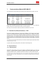
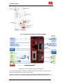
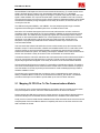
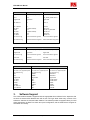
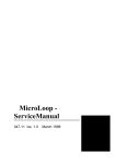
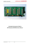
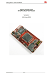
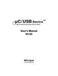
EDP‐AM‐CO1 Communications Module User Manual Version v4.0, 24/03/2010
This document contains information on the CO1 communications IO module for the
RS EDP system.
EDP-AM-CO1 Manual
Contents 1. 1.1 1.2 1.2.1 1.2.2 1.3 1.4 Communications Module EDP-AM-C01
3 Controller Area Network Interfaces - CAN ..................................... 3 Serial Interfaces............................................................................. 3 RS232 Interfaces ........................................................................... 3 RS485 ........................................................................................... 4 USB Interface ................................................................................ 4 Real Time Clock IC........................................................................ 4 2. 2.1 User Jumpers And Connectors
4 Mapping Of CPU Pins To The Communications Module ............... 6 3. Software Support
© Electrocomponents plc
7 Page 2
EDP-AM-CO1 Manual
1.
Communications Module EDP-AM-C01
This module allows the easy interfacing to the following communication devices present on the CM:
Comms Type RS232 RS232 RS485 USB device CAN CAN CAN Channel No. ASC0 ASC0 ASC1 ASC1 USB DEV CAN CNTRL CAN CNTRL CAN1 Connector 9D Male 5x2 Header 5x2 Header 5x2 Header USB mini socket 9D Female 5x2 Header 5x2 Header Name J305 P302 P301 P301 Comment p3 = RX, p5 = TX p3 = RX, p5 = TX P303 P201 P204 P204 Where available on CM 120R on baseboard Opto‐isolated CAN Opto‐isolated CAN It also carries a PCF8583 real time clock device on the I2C bus and 240 bytes of non-volatile data
storage, powered from the optional lithium battery on the EDP baseboard.
Note: Only one communications module may be fitted to a baseboard at any one time.
1.1 Controller Area Network Interfaces - CAN
The first CAN channel (CAN0) from the CM (where available) is routed through the 9-D female
connector as CAN-High and CAN-Low signals, ready for interfacing to an existing CAN network.
CAN0 may also be routed through a galvanically isolated CAN physical layer, emerging on P204 and
selectable via P205. If this is required, CAN0 TX and RX connections to the CPU on the CM must be
isolated via jumpers on the CM itself (please refer to the user manual for the CM fitted). The isolated
physical layer has its own 5V DC-DC convertor so that the EDP system can float relative to other CAN
devices.
If the CM has a second CAN channel (CAN1), this can also be routed through the galvanically isolated
CAN physical layer via P205.
An optional 120R CAN terminating resistor can be added via solder bridge J203.
1.2 Serial Interfaces
1.2.1 RS232 Interfaces
Asynchronous serial channel 0 from the CPU appears as RS232-level signals on the J305 9-D
connector. To allow the RS232 connector be mounted away from the EDP hardware, the same
signals are available on P302. A simple PC-style IDC 9D connector on a ribbon cable can be used.
For CMs that have a second asynchronous port, it can be routed to P301 where a PC-style IDC 9-D
with ribbon cable can be used. Alternatively it can be connected to an RS485 transceiver via jumpers
J302 and J303.
© Electrocomponents plc
Page 3
EDP-AM-CO1 Manual
1.2.2
RS485
RS485 communications are supported using a Linear Technology LTC485. To make use of this
option, the CM software must operate the Receive Enable/Data Enable control line. In RS485
installations where no load resistor is present, J306 allows a default one to be made available.
1.3 USB Interface
The AM unit provides support for USB ‘Device’ class only and does not provide any support for ‘Host’
class. The AM board provides a physical layer transient surge arrestor designed specifically to work
with high speeds found in USB communication. The USB interface works with those CMs that have a
USB peripheral on board that has been mapped to the RS-EDP backplane USB bus signals.
1.4 Real Time Clock IC
The AM module is fitted with an I2C based Real Time Calendar Clock IC. The device has an on board
32KHx watch crystal that maintains real time clock information. The device can be battery backed up
via a battery fitted to the Base Board. Interfacing to this device is done via the CNTRL_I2C signals. All
of the CMs currently designed are able to communicate to this device with this interface.
A set of software drivers is provided for each of the CM to allow easy access to this device. A driver
library provides software support for setting up sand configuring the RTC clock, as well as displaying
the information etc.
2.
User Jumpers And Connectors
User-configurable jumpers
P205 – Isolated CAN traffic selector
P205 1-3
P205 3-5
P205 4-6
P205 2-4
CAN0TX TTL traffic is routed to the isolated CAN transceiver
CAN1TX TTL traffic is routed to the isolated CAN transceiver
CAN0RX TTL traffic is routed from the isolated CAN transceiver
CAN1RX TTL traffic is routed from the isolated CAN transceiver
J302 & J303 Jumper Options – ASC1 - RS232/RS485 Selector
J302 2-3
ASC1 output is RS232 Rx Signal
J302 1-2
ASC1 output is RS485 B Signal
J303 2-3
ASC1 output isRS232 Tx Signal
J303 1-2
ASC1 output is RS485 A Signal
J304 – Real Time Clock Address Select
J304 1-2
A0 I2C Slave Address line is set high
J304 2-3
A0 I2C Slave Address line is set low (Default)
Changing the RTC salve I2C address may be required if there are other I2C devices in the system that
shares the same I2C address. Refer to the data sheet for the PCF8583T for the I2C address settings.
© Electrocomponents plc
Page 4
EDP-AM-CO1 Manual
P303: USB device
direct from CM
J203: Opto-coupled
CAN load resistor
P201: CAN0H & CAN0L
9-D, direct from CM
P205: Route CAN0 or
CAN1 to opto-coupled
CAN on P204
J305: ASC0 RX
& TX 9-D, direct
from CM
J304: Select RTC
I2C address
J306: Add RS485 120R resistor
J302: P301 p3 is ASC1 RX
or RS485 line B
J303: P301 p5 is ASC1 TX
or RS485 line A
P302: ASC0 RX
& TX direct from CM
P301: ASC1 RX
& TX or RS485 A & B
CO1 ‐ Communications Module to RS‐EDP Backplane
J305 & J302 UART0 RS232
ASC0TX_TTL
ASC0RX_TTL
ASC0TX
ASC0RX
P301 UART1 RS485 or RS232
ASC1TX_TTL
ASC1RX_TTL
ASC1RX_TTL_ASC0DSR
3
RS232
(RS485 Enable)
J303
2
ASC1TX
J302
1
3
2
ASC1RX
1
RS485
USBDEV+
USBDEV‐
P303 – Mini USB
D+
D‐
CAN0H
CAN0L 1
CAN0TX
CAN0RX CAN1TX
CAN1RX P205
5
P201 Straight through CAN
CAN0H
3
6
P205
4
2
CAN0L
P204 Isolated CAN
IRQ_GPIO16_CNTRL_I2C_INT
CANH
CANL
CNTRL I2C
VDDBAT Mapping of the Communications module to the backplane
The TTL levels for ASC0 are converted in to RS232 levels by the level shifter on the CO1 AM. The
output of this serial channel is on the 9 way D connector.
The ASC1 TTL levels can be converted to either RS232 levels or RS485 levels by selecting the
appropriate jumpers. To use RS485 successfully an additional third control signal is required. This is
© Electrocomponents plc
Page 5
EDP-AM-CO1 Manual
because RS485 is half duplex and hence it cannot transit whilst receiving. To control the flow a third
signal is required which is bought in from the backplane called ASC1RX_TTL_ASC0DSR.
Not all of the CPU Modules provide support for this signal, so please check with the CM to see if this
signal is made available. The output of this serial ASC1 channel is available on the P301 connector.
The user should connect a D connector to this, wired for RS232 or RS485 appropriately. Note: RS485
and RS232 have different pinning arrangement on the 9 way D connector, so check on-line for the
correct pin out for this.
The USB Device signals USBDEV+ and USBDEV- from the backplane pass through a transient
suppressor before exiting the RS-EDP system via a min USB connector P303.
Most of the CPU modules that support CAN have a local CAN transceiver on board, and hence
provide the option to supply either the TTL levels CAN0TX & CAN0RX or the physical layer signals
CANH and CANL. The CANH & CANL physical layer signals are routed directly onto the 9 way D
connector on the Communications Module. For normal operation the user would use the local CAN
transceiver on the CM and then route the physical layer CANH and CANL signals down the
backplane. The physical layer CAN traffic is then accessed via the 9 way D connector on the
Communication Module.
If the user would like isolated CAN traffic then the user would normally set up the Command CPU
Module to output TTL level CAN traffic, CAN0TX and CAN0RX instead. This TTL level traffic is then
routed via jumper on the Communications Module to a physical layer device which is electrically
isolated from the RS-EDP system. This floating CAN output is available on the P204 connector which
the user can then attach a 9 way D connector in the normal fashion to access the traffic.
In situations where the main CPU module has two CAN channels then the first CAN channel CAN0 is
set up for use with the local CAN transceiver on the CM. This will provide the CAN0H and CAN0L
physical layer signals that will appear on the 9 way D connector on the Communications Modules.
The second channel will be set up to output TTL level traffic on CAN1Rx and CAN1TX. This traffic is
then routed via the backplane to the Communications module where it is then selected via jumper to
enter the isolation circuit and physical layer CAN transceiver. CAN1 isolated physical layer traffic is
therefore available on P204.
The AM also has on board a Real time clock device which is supported during power down by a
battery on the Base Board. The RTC can be accessed via the CNTRL_I2C I2C bus. The AM also
provides an interrupt line to the MCU to provide wake up etc from RTC alarm events etc.
2.1 Mapping Of CPU Pins To The Communications Module
The connectors on the Communications Module are connected to the CPU module as shown below.
Only two examples are shown, one for the STR9 module and one for the XC167 module.
Please note that the USB device connector is inactive when the XC167 module is fitted and that that
the second serial port is not available when the Ethernet PHY is enabled on the STR9 module.
Finally, there is no second CAN channel available with the STR9 as the MCU does not have a second
CAN peripheral. Each of the CMs are different in capability and hence not all of the resource on the
AMs is available to all CMs.
© Electrocomponents plc
Page 6
EDP-AM-CO1 Manual
XC167 Pin Allocation STR9 Pin Allocation EDP‐AM‐CO1 Allocation Vcc to BB Vcc 3V3 or 5V, supplied by CM Vcc 3V3 or 5V, supplied by CM P3.2 Digital GND P5.6 Digital GND IRQ_GPIO16_CNTRL I2C INT Digital GND 86 CAN0 TX NC CAN1 TX 85 CAN0 RX 60 RxD1 P20.2 59 TxD1 69 TxD0 70 RxD0 Vcc 5V from reg NC P1.1 (PHY Disabled) P3.1 P1.0 (PHY Disabled) P5.0 P5.1 5V from baseboard regulator CAN1 RX ASC1 TX TTL ASC1 RX TTL_ASC0 DSR ASC1 RX TTL ASC0 TX TTL ASC0 RX TTL 5V from baseboard regulator Vcc 3V3 from reg 3V3 from baseboard regulator 3V3 from baseboard regulator XC167 Pin Allocation STR9 Pin Allocation EDP‐AM‐CO1 Allocation Vcc to BB Vcc 3V3 or 5V, supplied by CM Vcc 3V3 or 5V, supplied by CM Digital GND Vcc 5V from reg Digital GND 5V from baseboard regulator Digital GND 5V from baseboard regulator 3V3 Vbatt Vcc 3V3 from reg 3V3 Vbatt 3V3 from baseboard regulator 3V3 Vbatt 3V3 from baseboard regulator XC167 Pin Allocation Vcc 5V from reg Vcc 3V3 or 5V, supplied by CPU Vcc 3V3 from reg NC NC Digital GND 25 SDA2 26 SCL2 CANL0 CANH0 87 CAN1 TX 84 CAN1 RX 3.
STR9 Pin Allocation Vcc 5V from reg Vcc 3V3 or 5V, supplied by CPU Vcc 3V3 from reg USBDN USBDP Digital GND P2.1 P2.0 CANL0 CANH0 P3.2 P3.3 EDP‐AM‐CO1 Allocation Vcc 5V from reg Vcc 3V3 or 5V, supplied by CPU Vcc 3V3 from reg USB DEV D+ USB DEV D‐ Digital GND CNTRL I2C SDA CNTRL I2C SCL CANL0 CANH0 CAN0 TX CAN0 RX Software Support
The Communication Module is supported with the appropriate driver software for the respective CM.
As there are several CPU Modules each with its own CPU type there exists many versions of the
software to exercise the Communication Module. The software provides a supported library for CAN
where appropriate, the Real Time Clock set up and configuration, and the UART drivers. Support for
the USB is not currently.
© Electrocomponents plc
Page 7