1
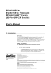
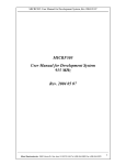
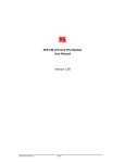
EDP‐AM‐AN16 Analog Input Applications Module User Manual Version v4.0, 29/03/2010
This document contains information on the AN16 analog input module for the
RS EDP system.
EDP-AM-AN16 Manual
Contents 1. Analog Input Module
3 1.1 Anti-Aliasing Filters ........................................................................ 3 1.2 Additional Items ............................................................................. 4 1.3 Setting Jumper Options ................................................................. 4 1.3 Software Drivers For Analog Module ...................................................... 6 1.4 Mapping Of CPU Peripheral Pins To The Analog Module.............. 6 1.5 Analog Module Input Characteristics ............................................. 7 1.5.1 Channels AN0-AN7 ....................................................................... 7 1.5.2 Channels AN8- AN15 .................................................................... 8 1.6 Analog Module Hints...................................................................... 9 © Electrocomponents plc
Page 2
EDP-AM-AN16 Manual
1.
Analog Input Module
The EDP-AM-AN16-A analog module allows up to 32 analog channels to be interfaced to the CM
(CPU Module or Command Module). It has a mix of filtered and unfiltered inputs and two precision
voltage sources for accurate absolute measurements.
The on-board MAX1138 ADC is accessible via I2C CNTRL bus and gives up to 12 extra channels of
10-bit analog to digital conversion. Each of the first 12 channels can be routed via jumpers to either
the CM’s own ADC or to the on-board ADC. In addition, any unused channels on the on-board ADC is
available on a connector, meaning a total of 16 plus 12, i.e.28 channels are possible.
Two analog modules may be fitted simultaneously. If this is the case the 16 analog channels, which
are fed directly down the backplane to the ADC on the MCU have to be allocated to each of the two
modules respectively but the 12 additional ADC channels present on each of the AMs can be read
independently, giving a total of 16 plus 12 plus a second 12. i.e. a total of 40 channels.
If a second module is fitted, the channels belonging to the CM remain the same, although the user can
specify which channel will be routed through which analog module. The second analog module must
use the second I2C channel, I2C_GEN0 as the MAX1138 ADC has a fixed I2C address. An
alternative version of this device (MAX1138KEEE+) has a different I2C address and can be fitted to
the second module if required.
The on-board ADC is by default the MAX1138 5V, 10-bit ADC but the alternative MAX1139 3V3
device can be fitted. The CM analog channels have a voltage range determined by the CPU fitted.
The analog module inputs are able to cope with a 0-5V range, regardless of the CM type fitted. It is
therefore up to the user to ensure that the voltage applied to the inputs does not exceed that required
by the CM. A series protection resistor may optionally be fitted to reduce the chance of damaging a
3V3 ADC if 5V is applied.
The 5V and 3V3 precision references can be applied to the CM’s ADC and the on-board ADC,
although the latter will sacrifice one channel if this is used. They can also be fed back to the CM via
the VAREF EDP signal.
Ratiometric conversions are possible using a special output pin on connector P201 pin1 for driving
resistive sensors.
Quantity Type 2 6 8 12 1 1 2 pole filters with digitally controlled cut‐off 2‐pole active filters with fixed cut‐off 1‐pole passive filters with fixed cut‐off Unfiltered channels 5V reference 3V3 reference 1.1 Anti-Aliasing Filters
Channels AN0 to AN7 are equipped with 2-pole, Sallen-Key anti-aliasing filters, configured in a
Butterworth mode.
The active filters are unity gain so they can be used for DC voltage
measurements as well as for sampling rapidly changing signals. Channels AN0 and AN1 optionally
have I2C-controlled 256 step digital potentiometers which allow the filter characteristics to be altered
under software control. They can also be cascaded to yield a single 4-pole filter on channel AN0.
The remaining active filters have a cut-off frequency of 12kHz.
© Electrocomponents plc
Page 3
EDP-AM-AN16 Manual
By fitting the appropriate resistors to the potential dividers on the filter inputs (R301, R304 etc.), the
input voltage range can be extended to suit the user’s application on a channel-by-channel basis.
AN8-AN15 have simple low-pass filter inputs. All inputs are protected against over-voltage conditions.
1.2 Additional Items
A trimmer potentiometer and light-dependent resistor and are fitted to channels AN0 and AN1
respectively for educational purposes.
1.3 Setting Jumper Options
Some options are made using black 2mm links. These are available from RS under part number 1809353. The possible user settings are listed below, along with their default configurations.
Jumper
Type
J202
Solder
J204
J205
J301
J302
J303
J305
J306
J307
J308
J309
J310
J311
J312
J313
J314
J201
JP201
JP202
JP203
JP204
JP205
JP206
JP301
JP302
P201
Solder
Solder
Solder
Solder
Solder
Solder
Solder
Solder
Solder
Solder
Solder
Solder
Solder
Solder
Solder
4W Link
Link
Link
Link
Link
Link
Link
Link
Link
2-way
© Electrocomponents plc
Purpose
Default
Set voltage for MAX1138 ADC
1-2
Set I2C channel
Set I2C channel
Connect local VAGND to SGND on module rather on CPU module (NO)
Route AN0_5V to CPU AN0 or MAX1138 AN0; enable 5V to 3V3 scaling for CPU AN0
Enable shutdown mode for AD5263 (Default 2-3)
Set AD5263 I2C address AD0
Set AD5263 I2C address AD1
Create 4-pole active filter from U301A and U301B
Route AN4_5V to CPU AN4 or MAX1138 AN4; enable 5V to 3V3 scaling for CPU AN4
Route AN1_5V to CPU AN1 or MAX1138 AN1; enable 5V to 3V3 scaling for CPU AN1
Route AN5_5V to CPU AN5 or MAX1138 AN5; enable 5V to 3V3 scaling for CPU AN5
Route AN6_5V to CPU AN6 or MAX1138 AN6; enable 5V to 3V3 scaling for CPU AN6
Route AN2_5V to CPU AN2 or MAX1138 AN2; enable 5V to 3V3 scaling for CPU AN2
Route AN7_5V to CPU AN7 or MAX1138 AN7; enable 5V to 3V3 scaling for CPU AN7
Route AN3_5V to CPU AN3 or MAX1138 AN3; enable 5V to 3V3 scaling for CPU AN3
Select source for MAX1138 REF
Select ADC for AN8_5V input
Select ADC for AN9_5V input
Select ADC for AN10_5V input
Select voltage for VAREF
Select ADC for AN11_5V input
Select source for AN15 input
Select AN0_5V or pot as AN0 input
Select AN1_5V or LDR as AN1 input
Power supply to ratiometric sensors
Page 4
1-2
1-2
1-2
1-2
2-3
2-3
2-3
Open
1-2
1-2
1-2
1-2
1-2
1-2
1-2
Open
1-2
1-2
1-2
1-2
1-2
2-3
1-2
1-2
NC
EDP-AM-AN16 Manual
The locations of the most important user-selectable items are shown below.
P203: Direct 5V analog input
to MAX1138
J201: Select source for MAX1138 REF
JP204: Select voltage for VAREF
JP206: Select source for AN15
JP202: Select ADC for AN9_5V
JP201:Select ADC for AN8_5V
JP205:Select ADC for AN11_5V
JP203: Select ADC for AN10_5V
J202: Set voltage for MAX1138 ADC
JP302: Select AN1_5V or LDR as AN1 input:
J205: Set I2C channel
J204: Set I2C channel
J305: Set AD5263 I2C address AD0
JP301: Select AN0_5V or pot as AN0 input
J306: Set AD5263 I2C address AD1
J302: Route AN0_5V to CPU AN0 or MAX1138 AN0; enable 5V to 3V3 scaling for CPU AN0
J309 :Route AN1_5V to CPU AN1 or MAX1138 AN1; enable 5V to 3V3 scaling for CPU AN1
J307: Create 4-pole active filter
J312: Route AN2_5V to CPU AN2 or MAX1138 AN2; enable 5V to 3V3 scaling for CPU AN2
J303: Enable shutdown mode for AD5263 (Default 2-3)
J314: Route AN3_5V to CPU AN3 or MAX1138 AN3; enable 5V to 3V3 scaling for CPU AN3
J310: Route AN5_5V to CPU AN5 or MAX1138 AN5; enable 5V to 3V3 scaling for CPU AN5
J308: Route AN4_5V to CPU AN4 or MAX1138 AN4; enable 5V to 3V3 scaling for CPU AN4
P202: 5V analog inputs to
CPU ADC or MAX1138
J311: Route AN6_5V to CPU AN6 or MAX1138 AN6; enable 5V to 3V3 scaling for CPU AN6
J313: Route AN7_5V to CPU AN7 or MAX1138 AN7; enable 5V to 3V3 scaling for CPU AN7
J301: Connect local VAGND to SGND on module rather on CPU module (NO)
P201: Power supply to ratiometric sensors
AN16 ‐ Analogue Module to RS‐EDP Backplane
P202 Analogue
Input Connector
AN0
AN1
AN2
AN3
AN4
AN5
AN6
AN7
AN8
AN9
AN10
AN11
AN12
AN13
AN14
AN15
CNTRL I2C
2
1
JP204
3
I2C GEN0
JP206
3
JP309
1
JP312
1
JP314
1
JP308
1
JP310
1
JP311
1
JP313
1
JP201
1
JP202
1
JP203
1
JP205
1
I2C Data
I2C CLK
2
JP205
2
3
1
2
3
2
3
2
3
2
3
2
3
2
3
2
3
2
3
2
3
2
3
2
3
AN0_5V
AN1_5V
AN2_5V
AN3_5V
AN4_5V
AN5_5V
AN6_5V
AN7_5V
AN8_5V
AN9_5V
AN10_5V
AN11_5V
AN12_5V
AN13_5V
AN14_5V
AN15_5V
I2C
J301
SGND
VAGND
VAREF
1
3
1
2
1
JP301
2
JP204
1
3
3.3Vref
5.0Vref
I2C bus can only read inputs AN0_5V to AN11_5V
Block diagram of the Analog Module showing capability and basic link options. Normally AN0_5V to
AN15_5V are used for the raw analog inputs. The processed analog signals are passed to the MCU
via the backplane on AN0-AN15 or redirected into the on board ADC for reading via an I2C chip. With
this implementation a total of 16 analog inputs are available, the first 12 of which are readable via I2C.
You can also see that the analog ground (VAGND) and the digital signal ground (SGND) can be
connected via a zero ohm link. This link is normally left open as the same link is available on the CPU
modules. The CPU modules should normally use this option to connect the two grounds. Most of the
© Electrocomponents plc
Page 5
EDP-AM-AN16 Manual
CPU modules should have this feature but check the circuit diagram and mapping aids on the
respective CPU Modules.
The analogue board is capable of producing a very stable voltage reference signal. This signal can be
passed down the backplane as required to other modules. The CPU modules for example can use this
as a reference for their on board ADC’s. The AM is fitted with both a 3.3V and 5.0V voltage reference
source. The user selects between them as shown in the diagram. Some CPU Modules can output
their own reference on to the backplane also so the user must also check for contention on this signal
line.
The on board ADC and the digital potentiometers present on the AM can be controlled via I2C.
Normally the user would use the CNTRL_I2C bus option rather than the I2C_GEN0 bus option. The
I2C_GEN0 bus is provided as a secondary I2C interface for the customers own I2C network. Not all
CPU Modules can support the second I2C bus.
The drawing is from a Mapping Aid document which is provided for each of the CPU Modules.
1.3 Software Drivers For Analog Module
The module has two I2C devices, both of which require special software drivers to access. The
software drivers are provided for the CNTRL_I2C bus for each of the Command Modules currently in
production. The software drivers allow for the easy access to the resources available on this
Application Modules. As each piece of software is different for each of the CMs, you will need to refer
to the software pack for each of these CMs for more details.
1.4 Mapping Of CPU Peripheral Pins To The Analog Module
The analog module passes down the backplane the processed analog signals AN0 to AN15. These
may well have been processed by the on board filters on the AM for example.
The AN0-AN15 signals can be directly read by the CPU module. Not all of the CMs can read all of the
AN0-AN15 signals as the resources available on each MCU are all different. To help with the matching
up of CMs and Application Modules (AMs) a Mapping Aid document exists for each of the Command
Modules. This details the resources that are available on the MCU with the resources available on the
AMs. The page relating to the Analogue Module is shown below
The analog inputs on connector P202 on the analog IO module are connected to the CPU module as
shown below. The mapping is shown for the STR9 and XC167 modules below.
XC167 Pin Allocation Vcc to BB STR9 Pin Allocation Vcc 3V3 or 5V, supplied by CM EDP‐AM‐AN16 Allocation Vcc 3V3 or 5V, supplied by CM 42 GUARD/AN GND P3.5 P3.2 Digital GND 37 AN8 39 AN6 33 AN4 31 AN2 45 AN14 43 AN12 AVSS Analog GND P5.7 P5.6 Digital GND NC P4.6 P4.4 P4.2 NC NC VAGND IRQ_GPIO18_I2C GEN0 INT IRQ_GPIO16_CNTRL I2C INT Digital GND AN8 AN6 AN4 AN2 AN14 AN12 35 AN10 NC AN10 29 AN0 41 VAREF P4.0 AVREF ‐ Analog AN0 AN_REF © Electrocomponents plc
Page 6
EDP-AM-AN16 Manual
Vcc 5V from reg 5V from baseboard regulator 5V from baseboard regulator Vcc 3V3 from reg 3V3 from baseboard regulator 3V3 from baseboard regulator Pin XC167 Pin Allocation 126 Vcc to BB STR9 Pin Allocation Vcc 3V3 or 5V, supplied by CM EDP‐AM‐AN16 Allocation Vcc 3V3 or 5V, supplied by CM 20 132 12 10 8 6 18 16 14 4 130 AVSS Analog GND Digital GND NC P4.7 P4.5 P4.3 NC NC NC P4.1 5V from baseboard regulator 3V3 from baseboard regulator VAGND Digital GND AN9 AN7 AN5 AN3 AN15 AN13 AN11 AN1 5V from baseboard regulator 22 80 P4.0 P8.1 24 81 P4.1 P8.2 GUARD/AN GND Digital GND 38 AN9 40 AN7 34 AN5 32 AN3 46 AN15 44 AN13 36 AN11 30 AN1 Vcc 5V from reg 128 Vcc 3V3 from reg 2 NC XC167 Pin Allocation Vcc 5V from reg Vcc 3V3 or 5V, supplied by CPU Vcc 3V3 from reg 23 SDA1 24 SCL1 Digital GND 25 SDA2 26 SCL2 3V3 from baseboard regulator STR9 Pin Allocation Vcc 5V from reg Vcc 3V3 or 5V, supplied by CPU Vcc 3V3 from reg P2.3 P2.2 Digital GND P2.1 P2.0 EDP‐AM‐AN16 Allocation Vcc 5V from reg Vcc 3V3 or 5V, supplied by CPU Vcc 3V3 from reg I2C GEN0 SDA I2C GEN0 SCL Digital GND CNTRL I2C SDA CNTRL I2C SCL Refer to the Mapping Aids to get an overview of what resources the module can connect to.
1.5 Analog Module Input Characteristics
1.5.1 Channels AN0-AN7
These are over-voltage protected and buffered with unity gain, 2nd order filters. The characteristics of
the OP amps fitted mean that the usable voltage input range is 24mV to 4.49V, with a linear and
monotonic response. With a 5V, 10-bit ADC the decimal value range is from 9 to 804 bits. With a
3V3, 10-bit ADC, the upper value is 1023 bits.
© Electrocomponents plc
Page 7
EDP-AM-AN16 Manual
1.5.2 Channels AN8- AN15
These are un-buffered but still have over-voltage protection. The usable range is determined entirely
by the characteristics of the ADC used.
© Electrocomponents plc
Page 8
EDP-AM-AN16 Manual
1.6 Analog Module Hints
For best performance when using the CPU’s own ADC, i.e. least noise and greatest conversion
accuracy, ensure that the analog module is placed in the EDP baseboard position immediately
adjacent to the CPU module. Also, solder bridge J301 can be closed to ensure that the analog ground
is connected to the system ground (SGND) on the analog module rather than on the CPU module.
However to avoid ground loops though, the link on the CPU module that connects these two grounds
must be opened (XC167 only).
© Electrocomponents plc
Page 9