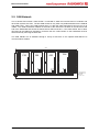
1
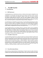
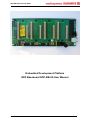
EDP-BB-4A Technical Notes
Embedded Development Platform
EDP Baseboard EDP-BB-4A User Manual
© Electrocomponents plc
Vsn 1.1
Page 1
EDP-BB-4A Technical Notes
Contents
1.
1.1
1.1.1
1.1.2
1.1.3
1.2
1.3
1.3.1
1.3.2
1.3.3
1.4
1.4.1
1.5
1.6
The EDP System
3
Introduction ..................................................................................... 3
EDP Baseboard .............................................................................. 3
Reusable Components.................................................................... 3
Bread-Boarding Platform................................................................. 3
EDP Modules Available Now .......................................................... 4
Basic EDP Concepts ....................................................................... 4
Standardised Signal Set for Embedded Microcontrollers ............... 5
Grouping of Signals on the EDP Connectors ................................. 6
EDP Signal Names ......................................................................... 8
The EDP Virtual CPU Concept ....................................................... 9
Example of Real CPU to EDPCON Mapping ................................ 11
Inter-Module Communication ........................................................ 14
Inter-EDP System Communications ............................................. 14
2.
2.1
2.2
2.3
2.4
2.5
2.6
2.6.1
2.6.2
2.7
2.8
2.8.1
2.9
Using the EDP Baseboard
15
EDP Connectors ........................................................................... 15
EDP Baseboard User Options Placement .................................... 16
EDP Baseboard Component Placement....................................... 17
EDP I/O Pin Headers .................................................................... 18
Grounding Arrangements .............................................................. 19
Positive Supplies ........................................................................... 19
Logic Supplies ............................................................................... 19
Analogue Supply ........................................................................... 20
Limits and Restrictions .................................................................. 20
EDP Control Busses ..................................................................... 21
2
I C Busses..................................................................................... 21
CAN Network ................................................................................ 23
© Electrocomponents plc
Vsn 1.1
Page 2
EDP-BB-4A Technical Notes
1.
The EDP System
1.1 Introduction
1.1.1 EDP Baseboard
The EDP Baseboard (or “motherboard”) consists of 4 „stations‟ with the minimum configuration of the
motherboard with a single plug-in processor module. All 4 stations are identical, and there are many
permutations of CPU modules and Application modules possible. Even with just the minimum
configuration of Motherboard and CPU module for example, you can easily run a web-server through
the standard onboard Ethernet connection. There are various application modules; we have
introduced an initial starter range consisting of basic digital and analogue I/O, a motor control module
and a communications module. The more advanced user will discover that it is possible to run more
than one processor module on the motherboard in a Master and Slave configuration.
The motherboard is an Extended Euro card size (220 x 100 mm) fitted with rubber feet to lay flat on
the bench, but able to be used in a standard rack system. Add a 64-way DIN (RS 381-8696) connector
and you can plug the EDP into a backplane. Connectors for four module stations are supplied,
arranged to ensure correct module fitting. There are also fitted +3.3V and +5V voltage regulators, a
back-up battery, an RJ45 Ethernet connector, a mini-USB connector, +12 volt power-supply jack, I/O
2
breakout header and eight DIP switches ported onto the system I C bus.
The DIP switches allow the user software running on a processor module to read a configuration
setting, enabling I/O ports to be set up correctly, for example, or for CAN or TCP/IP addresses to be
2
set. Depending on the capability of the particular processor module in use, up to three I C buses and
2
two CAN networks are available. Many of the application modules use an I C bus for primary
communication with the processor providing maximum flexibility. Some processor chips will require +5
volts, others +3.3 volts. A factory link on the module selects the correct supply from the connector.
This supply is linked to a further connector pin on all the other module stations providing a correct
voltage reference or bus pull-up for the application modules.
1.1.2
Reusable Components
The EDP baseboard is designed to be used and reused with new CPU and application modules being
introduced on a regular basis. Its robust design has been rigorously tested, and every effort has been
made at the design stage to protect the EDP from the most common human errors: the motherboard
will have a significantly longer life than the average development board and is suitable for use in
specialist one-off and low-volume products. Typical applications might be industrial controllers,
scientific instrument controllers, data-logging and remote monitoring. For these reasons the EDP will
prove attractive to all design engineers looking for a cost effective solution which allows them to
significantly improve their development process and thus deliver products in reduced time. Design
engineers, consultants, educators and trainers will quickly realise the benefits and recognise the
potential of the development platform modules system as an effective solution.
1.1.3
Bread-Boarding Platform
With the difficulty in applying traditional “bread-boarding” techniques to today‟s tiny SMT components,
evaluating new active devices has become major problem. There is usually no alternative to creating
a special “try-out” PCB using rapid PCB production houses just to get a new device up and running.
© Electrocomponents plc
Vsn 1.1
Page 3
EDP-BB-4A Technical Notes
The EDP has been designed to host such experimental and trial designs, providing “clean” +5 and
+3V3 supplies and instant access to a range of standard microcontrollers and I/O blocks and devices.
The design information necessary to allow you to create your own module for experimenting with new
devices is available free of charge but in many cases, RS will already have such a module available to
save you the effort.
The EDP represents the start of a continuous launch process which will see the introduction of new
processor and application modules on a monthly basis.
1.2 EDP Modules Available Now
Processor Module: ST Microelectronics STR912
Processor Module: Infineon XC167
Application Module: Analogue Input
Application Module: Digital Input/Output
Application Module: Brushed DC Motor Control
Application Module: Basic Communications
1.3 Basic EDP Concepts
The EDP allows microcontrollers and I/O devices to communicate through a standardised interface.
To some extent this interface is analogous to PC104 or STE busses where a connector pin-out is
defined that allows the interconnection of address and data-bus connected devices. Such busses tend
to include only power line, data and address busses plus control signals such as chip selects and
interrupt request lines.
For
microcontroller systems,
such a collection of signals is of very limited use, especially for single-chip CPUs that use no external
bus. It also takes no account of the specialist pin functions available on microcontrollers such as
2
CAN, I C, SPI, signal measurement and signal generation peripherals.
© Electrocomponents plc
Vsn 1.1
Page 4
EDP-BB-4A Technical Notes
1.3.1
Standardised Signal Set for Embedded Microcontrollers
The EDPCON1 and 2 connectors thus defines a set of signals on a standardised format that are
relevant to typical 8, 16 and 32-bit microcontrollers. In addition to address bus, data bus and chip
2
select signals, they include three I C channels, two CAN channels, groups of pins able to create
interrupts in response to external events, groups of pins able to create pulse-trains, others dedicated
2
to motor control, I S, memory cards and many other common microcontroller I/O types.
All of these signals are contained within two 0.8mm dual-row connectors of 140 and 100 pins each.
© Electrocomponents plc
Vsn 1.1
Page 5
EDP-BB-4A Technical Notes
1.3.2
Grouping of Signals on the EDP Connectors
The EDPCON1 and 2 connector specification divide the total available 240 pins into groups or regions
of similar characteristics, as shown below:
1.3.2.1 EDPCON1 Connector I/O Regions
EDPCON1 carries both analogue and digital signals. The analogue signals are grouped together in a
“quiet zone”.
© Electrocomponents plc
Vsn 1.1
Page 6
EDP-BB-4A Technical Notes
1.3.2.2 EDPCON2 Connector Regions
2
EDPCON2 carries mainly bus signals such as I C, SPI, CAN and the multiplexed 16-bit external bus
from the CPU module.
© Electrocomponents plc
Vsn 1.1
Page 7
EDP-BB-4A Technical Notes
1.3.3 EDP Signal Names
The generic signals present on the connectors have names which indicate their primary and
secondary functions.
1.3.3.1 EDPCON1 Signal Description
ANx:
VAGND:
GPIOx:
GPIOx_MCIxxx:
GPIOx_I2S_XXX:
IRQx_GPIOx_X_I2C_INT:
CPU_DACx_GPIOx:
EVMx_GPIOx:
GPIOx_ADx:
EVGx_GPIOx:
EVM2_GPIO41_CAPADC:
ASC0_RX_TTL:
ASC0_TX_TTL:
ASC1_RX_TTL:
ASC1_TX_TTL:
ASC1_TX_TTL_ASC0_DTR:
ASC1_RX_TTL_ASC0_DSR:
EVM_GPIOx_ASC0_xTS:
SPI_XXXX:
ETH_xxx:
I2C_GEN1_SDA/SCL:
MOTOR_XXXX:
EMRG_TRP:
CAN1_RX/TX:
VCC_CM:
+3V3:
+5V:
+12V:
12VGND:
SGND:
© Electrocomponents plc
Vsn 1.1
Analogue signals
Analogue ground, referenced to CPU and Analogue application
analogue signal grounds
Pins that can only be set to 1 or 0 by a CPU instruction. It has no
special or alternate function.
Pins that have basic I/O function like “GPIOx” but which also form an
SM/MMC card interface
Pins that have basic I/O function like “GPIOx” but which also form an
I2S interface.
2
Pins that are used by the three I C busses to request a CPU
interrupt. Note: IRQ_GPIO16_CNTRL_I2C_INT should always be
2
reserved for use by the I C CNTRL I2C bus.
Pins where CPUs with true digital to analogue converter outputs are
always connected. Alternatively, PWM will be available if there is no
DAC.
Pins which have basic I/O function but which also can measure timed
events, pulse times and durations e.g. CAPCOM input.
Pins with basic I/O function but which also can form a multiplexed
address and data bus.
Pins which have basic I/O function but which also can generate
events like timed pulses and transitions e.g. CAPCOM output.
Pins which have basic I/O function but which also can measure pulse
times and durations e.g. CAPCOM input. If the CPU supports the
triggering of ADC readings on an edge, the function will be on this pin.
Logic level connection to CPU module‟s serial port 0 receive pin.
Logic level connection to CPU module‟s serial port 0 transmit pin.
Logic level connection to CPU module‟s serial port 1 receive pin.
Logic level connection to CPU module‟s serial port 1 transmit pin.
If CPU supports DTR function on ASC0, the function is available here.
If CPU supports DSR function on ASC0, the function is available here.
Event measurement, general I/O and ASC0 RTS and CTS functions,
where available.
Pins associated with SPI function, where supported by CPU module.
Pins connected to an Ethernet PHY on CPU module, where available.
2
Pins connected to CPU‟s I C channel 1
Pins required for driving three-phase AC and DC brushless motors,
including inputs for Hall sensors and tachometers or other speedrelated signals.
Emergency stop/trip function for motor control.
Logic level connection to CPU module‟s second CAN module (where
fitted).
Peripheral operating voltage of CPU module currently fitted.
+3V3 supply from baseboard voltage regulator
+5V supply from baseboard voltage regulator
Raw +12V from power input to baseboard
Ground connection to power supply.
Digital logic ground (connects to 12VGND at star point in baseboard
Page 8
EDP-BB-4A Technical Notes
3V3 Vbatt:
Permanent +3V3 supply from Lithium cell on baseboard (where fitted)
1.3.3.2 EDPCON2 Signal Description
#RESIN:
#RESEOUT:
I2C_GEN0_SDA/SCL:
SGND:
Axx_ADxx:
Reset input to CPU module
Reset out signal from CPU module (where available)
2
Secondary I C bus data and clock (where available)
Digital logic ground (connects to 12VGND at star point in baseboard
16-bit multiplexed address/data bus when enabled by jumpers on
CPU module.
CPU module‟s address latch enable signal
CPU module‟s READ signal
CPU module‟s WRITE (or WRITELOW) signal
CPU module‟s WRITE (or WRITEHIGH) signal
CPU module‟s PSEN signal (8051) or A16, where available
CPU module‟s first chip select signal
CPU module‟s second chip select signal
CPU module‟s third chip select signal
CPU module‟s fourth chip select signal
Logic level connection to CPU module‟s first CAN module (where
fitted).
USB signals connected to FTDI USB-JTAG device on CPU module
Signals connected to CPU module‟s first SPI peripheral
2
Signals connected to CPU module‟s first or primary I C channel. (This
2
is the I C control backbone for the EDP baseboard).
CPU module‟s first CAN module via physical layer drivers.
Peripheral operating voltage of CPU module currently fitted.
+3V3 supply from baseboard voltage regulator
+5V supply from baseboard voltage regulator
Digital logic ground (connects to 12VGND at star point in baseboard
ALE:
#RD:
#WR:
#WRH:
#PSEN_A16:
#CS0:
#CS1:
#CS2:
#CS3:
CAN0_RX/TX:
USB-DEBUG+/CNTRL_SPI_XX:
CNTRL_I2C_SDA/SCL:
CANH0/CANL0:
VCC_CM:
+3V3:
+5V:
SGND:
1.4 The EDP Virtual CPU Concept
A microcontroller that has its I/O pins mapped appropriately onto the EDPCON1 and EDPCON2
connectors appears to be a virtual CPU to other I/O devices fitted on the bus. Thus for example, a 14bit ADC device on the EDPCON baseboard will see a CPU module also on the bus, as a virtual CPU
whose pinout is defined by the EDP bus. Currently two popular microcontrollers (Infineon XC167 and
ST STR9) have had their I/O pins mapped onto the EDPCON system. These two devices have some
features in common -UARTs, capture and compare pins, ADC, CAN but the STR9 also has USB
device. Thus the pin mapping to the EDPCON is not 100% in that on the XC167 version, the USB
device pins are unused. Both devices have dedicated motor control peripherals which although they
have different pin names, have virtually the same functionality.
Hence for example, a brushless DC motor control module with half-bridges can be designed to
interface to the motor control region of the EDPCON bus without any regard for the CPU type to be
ultimately used.
The net result is that subject some limitations, a range of modules bearing different CPUs can be
freely connected to a range of I/O modules.
The EDPCON has been designed to accommodate all the common peripherals found on current
2
microcontrollers, including advanced interfaces like SD/MMC and I S. Thus it is possible to map
almost any microcontroller to this format.
© Electrocomponents plc
Vsn 1.1
Page 9
EDP-BB-4A Technical Notes
XC167
STR9
EDPCON2
1
EDPCON2
1
140
100
© Electrocomponents plc
Vsn 1.1
100
Page 10
EDPCON 240 Pin Virtual CPU
140
EDPCON 240 Pin Virtual CPU
EDPCON1
1
EDPCON1
1
EDP-BB-4A Technical Notes
1.4.1
Example of Real CPU to EDPCON Mapping
This is the mapping developed for the Infineon XC167 and used on the RS-EDP-CM-XC167 module.
1.4.1.1 Infineon XC167 – EDPCON1 Mapping
This mapping assigns the XC167 pins (and hence peripherals) into the appropriate regions on the
EDPCON1 connector.
© Electrocomponents plc
Vsn 1.1
Page 11
EDP-BB-4A Technical Notes
© Electrocomponents plc
Vsn 1.1
Page 12
EDP-BB-4A Technical Notes
1.4.1.2 Infineon XC167 – EDPCON2 Mapping
142 #RSTIN
3 #RSTOUT
23 SDA1
24 SCL1
Digital GND
116 AD15
115 AD14
114 AD13
113 AD12
112 AD11
111 AD10
106 AD9
105 AD8
102 AD7
101 AD6
100 AD5
99 AD4
98 AD3
97 AD2
96 AD1
95 AD0
93 #ALE
90 #RD
91 #WRL
75 #WRH
A16
7 #CS0 (SRAM)
8 #CS1 (CS8900)
9 #CS2
10 #CS3
84 CAN1 RX
87 CAN1 TX
USB DEBUG D+
USB DEBUG D76 SCLK0
67 MRST0
68 MTSR0
82 P4.2
25 SDA2
26 SCL2
NC
NC
NC
NC
CANH control physical layer (CAN1)
CANL control physical layer (CAN1)
CPU‟s Vcc 3V3 or 5V
Vcc 3V3 from reg
Vcc 5V from reg
Digital GND
© Electrocomponents plc
Vsn 1.1
Page 13
EDP-BB-4A Technical Notes
1.5 Inter-Module Communication
With up to four modules on the EDPCON bus, some form of inter-module communication is required.
With a limited number of CPU pins available, it is necessary to use a serial communications protocol
to, for example, take readings from a high-precision ADC at the same time as read a serial EEPROM
2
on a further module. The I C protocol is used as the main communication channel for such actions,
although provision is made for SPI or even a CAN physical layer.
Module
Possible
Range
I2C Device
Actual 7-bit
Address
I2C channel
Actual 7-bit
Address
Module 1
Baseboard
Analogue AM
I2C channel
Comment
Module 2
PCF8575TS
0x20 - 0x27
0x20
CNTRL
XXXX
XXXX
DIP configuration switches
24C32 (Rev B)
0x50 - 0x57
0x51
CNTRL
0x52
CNTRL
4 kbyte EEPROM
MAX1138EEE
0x35
0x35
CNTRL
0x35
Gen0
12-channel 10-bit ADC
AD5263BRU50
0x2C - 0x2F
0x2C
CNTRL
0x2C
Gen0
Digital Potentiometer
Comms AM
PCF8583
0x50 - 0x51
0x50
CNTRL
XXXX
XXXX
Real-Time Clock and RAM
Digital AM
PCF8575TS
0x20 - 0x27
0x22
CNTRL
0x24
CNTRL
16-channel digital input
PCF8575TS
0x20 - 0x27
0x23
CNTRL
0x25
CNTRL
16-channel digital output
2
There are three possible I C channels available although in most cases the default one (I2C_CTRL)
2
will be sufficient. EDP modules that carry I C device do, where possible, allow the user to configure
2
the I C addresses. This allows for example, up to three digital I/O modules to be fitted, with the GPIO
2
devices on each module given an unique address. Where the address space of a particular I C
channel becomes full, devices can be connected to an alternative channel to get access to a
completely new address space.
1.6 Inter-EDP System Communications
In a situation where there are multiple EDP baseboards, each with their own CPU modules in a
2
complete system, an I C bus can still be used to allow the CPUs to communicate, but the use of a
CAN bus is strongly recommended. EDP I/O signals that are intended to be taken off-board are
brought out on a standard DIN41612 64-way connector.
© Electrocomponents plc
Vsn 1.1
Page 14
EDP-BB-4A Technical Notes
2.
Using the EDP Baseboard
This section gives information on the features of the EDP baseboard, its connectors and the overall
structure of the EDP system.
2.1 EDP Connectors
The EDP bus contained in the EDP baseboard is accessed through two Tyco-AMP 0.8mm pitch
connectors. The signal names are intended to convey something of the capabilities of that signal. For
example signal EVG0_GPIO40 is a pin that can generate timed events (i.e. pulses and pulse trains)
as well as performing simple on/off pin control.
EDPCON2 Connector
EDPCON1 Connector
© Electrocomponents plc
Vsn 1.1
Page 15
EDP Technical Notes
2.2 EDP Baseboard User Options Placement
There are a number of user-selectable functions on the baseboard, as shown below:
S502: 8W DIP switch to
allow user settings via I2C
8W DIP switch I2C
address A0
S501: CPU reset
P401: CAN CTRL 120R
terminating resistor
J601-J603: EEPROM
I2C addresses E0,E1,E2
P501: 12V high current
screw terminals
J502: 12V , 2A
jack socket
P601: IO pin headers
P602: IO pin headers
P603: IO pin headers
P504: Connect CPU analog
ground to system ground
(SGND)
© Electrocomponents plc
Vsn 1.1
Page 16
EDP Technical Notes
2.3 EDP Baseboard Component Placement
The location of the major items on the EDP baseboard is shown below.
© Electrocomponents plc
Vsn 1.1
Page 17
EDP Technical Notes
2.4 EDP I/O Pin Headers
All the signals in the EDP backplane are available here on 0.1” pin headers for connection to test
equipment, etc.
© Electrocomponents plc
Vsn 1.1
Page 18
EDP Technical Notes
2.5 Grounding Arrangements
The system ground (SGND) and 12V ground (12V_GND) are connected together at a star point on the
baseboard. The 12V GND is used for high current devices like the motor controller and the Darlington
output drivers on the digital I/O module. System ground is used for all returns on logic devices on all
modules. It can be used for analogue returns but there is a risk of noise (ground bounce).
Analogue ground (VAGnd) by default is an offshoot of the system ground which occurs only on the
CM. It is routed to the VAGnd pins of the CPU and also acts as a return for filter circuits used for
analogue inputs. It is optionally possible to connect the SGND to the Analogue ground on the
analogue module, although this should not be necessary unless there are a large number of resistive
sensors being used. In this case, the link connecting VAGnd and SGND on the CM must be opened
to avoid ground loops.
This is determined by the CPU
module design. It is not a
movable link!
+12V
Vcc_CM
+12V
CPU Module
Motor Module
Analog Module
Fuse
Precision
Volt Ref.
IO signal
conditioning
VAREF
3V3 Reg
Default: EDP+12V
Select +12V source
Vcc_CM
Filter
R
AN15 ref
VAREF
Connect
CPU VAGND
to digital GND
on CM module.
Default: closed
ANx
ADC
Ratiometric
sensor
VAGND
VAGND
Motor
Driver
REF
I2 C AD C
5V Reg
Rs
GND
DC
Motor +
Motor 12vHC
Connect
CPU VAGND
to digital GND
on CM module.
Default: open
12vGND
VAGND
System_GND (SGND)
12V_GND
12V GND
Direct high current connection
to motor controller (bypass
EDP 12VGND and +12V)
2.6 Positive Supplies
The +12V line comes via the screw terminals on the baseboard or the mini-jack. It is fused and filtered
before entering the EDP backplane. The +3V3 and +5V voltage regulators are driven from the +12V.
2.6.1
Logic Supplies
Both +3V3 and +5V are available on the EDPCON to support both +5V and +3V3 processors and
devices. To allow the interfacing of I/O devices at the required voltage, the positive supply to the CPU
I/O domain is routed into the EDPCON through Vcc_CM. It is intended to be used for pull-ups on I/O
pins and powering small active components that connect directly to the CPU such as discrete logic,
op-amps etc. Vcc_CM is limited to 500mA total current draw from other modules and the baseboard.
Vcc_CM is connected inside the CM to the voltage used by the CPU‟s I/O domain.
© Electrocomponents plc
Vsn 1.1
Page 19
EDP Technical Notes
2.6.2
Analogue Supply
The Analogue supply to the CPU ADC may be derived from the local Vcc or from a precision
reference located on the Analogue AM. Ideally the Analogue AM and CM should be in adjacent
positions on the baseboard to keep the signal length to a minimum if the latter is chosen.
2
The I C ADC on the analogue module can use the Vcc_CM or the local precision voltage references,
either +3V3 or +5V. The 5V reference is driven from the 12V to guarantee no drop-out problems.
As the anti-aliasing filters are run at +5V, the local ADC is not tied to the same voltage range as the
CPU‟s ADC. It is the user‟s responsibility to make sure that the input does not exceed the permissible
input voltage range of the CPU ADC. Protection resistors are provided to prevent damage.
2.7 Limits and Restrictions
Vcc CM max current ……………………………….. 500mA
3V3 max current ……………………………………. 2000mA
5V max current ……………………………………… 2000mA
3V3 current + 5V current + Vcc_CM …………. 2000mA
SGND max current …………………………………. 2000mA
12VGND max current ………………………….….. 2000mA
Warning: Only attempt to fit two CPU modules to the baseboard at the same time when you are really
certain you know what you‟re doing! If they have different peripheral supply voltages then damage is
likely to occur.
© Electrocomponents plc
Vsn 1.1
Page 20
EDP Technical Notes
2.8 EDP Control Busses
I2C Busses
2.8.1
2
The EDP uses I C as the data and control backbone. Depending on the capabilities of the CM fitted,
2
2
2
up to three independent I C busses are available. I C channel “CNTRL_I2C” is the primary I C device
2
bus and is used by default to communicate with I C devices on the baseboard and application
modules.
2
2
The I C address space is based on the 7-bit addressing scheme. I C devices that are able to
generate an interrupt request by default use the IRQ_GPIO16_CNTRL_I2C_INT line, with the option
of using up to another three interrupt-capable lines.
A pull-up resistor is provided on
2
IRQ_GPIO16_CNTRL_I2C_INT so that the open collector /INT outputs on I C devices can signal an
interrupt by pulling this line down.
2
The I C bus runs at +3V3 so any +5V devices must be connected via a level shifting mechanism.
2
The I C bus devices require pull-up resistors on the SDA and SCL lines and these are incorporated on
the baseboard.
2
There are three possible I C channels available although in most cases the default one (I2C_CTRL)
2
will be sufficient. EDP modules that carry I C device do, where possible, allow the user to configure
2
the I C addresses. This allows for example, up to three digital I/O modules to be fitted, with the GPIO
2
devices on each module given a unique address. Where the address space of a particular I C
channel becomes full, devices can be connected to an alternative channel to get access to a
completely new address space.
3V3
CM
4K7
AM
AM
AM
IRQ
IRQ
IRQ
IRQ
3V3
3V3
4K7
PCF85 75
SCL
/INT
4K7
CNTRL_I2C
SDA
4K7
Only CMs can optionally
have pull-ups to 3V3
© Electrocomponents plc
Vsn 1.1
Page 21
3V3
3V3 I2C_GEN0
I2C_GEN1
GPIO16_CNTRL_I2C
GPIO18_GEN0_I2C
GPIO22_GEN1_I2C
GPIO24_I2C_INT
EDP Technical Notes
2.8.1.1 Available I2C Interrupt Request Lines
2
Each of the three potential I C channels has a dedicated interrupt request line into the CM. A spare
interrupt line is provided that can be allocated to any channel, as defined by the user. However it is up
2
to the user to make sure that the software is able to recognise the I C device that requested the
interrupt.
I2C_CTRL
I2C_GEN0
I2C_GEN1
Uncommitted
© Electrocomponents plc
IRQ GPIO16_CNTRL_I2C
IRQ GPIO18_GEN0_I2C
IRQ GPIO22_GEN1_I2C
IRQ GPIO24_I2C_INT
Vsn 1.1
Page 22
(integral pull-ups)
(integral pull-ups)
(integral pull-ups)
(integral pull-ups)
EDP Technical Notes
2.9 CAN Network
The on-board CAN network “CAN CNTRL” is intended to allow the interconnection of modules and
other EDP systems via CAN. The first CAN module on any CPU is by default allocated to the CANH0
and CANL0 bus. This is the CAN physical layer (i.e. after the CAN transceivers) and can run at up
1MB/s. The 120R termination resistors at the ends of the network are located on the CM and at the
end of the baseboard that carries the Ethernet and USB connectors. If the CAN CNTRL bus is taken
off-board via the DIN41612 expansion connector then the 120R resistor on the baseboard must be
disconnected by removing the P201 link.
The CAN CNTRL bus is available through a 9-way D-connector on the optional EDP-AM-CO1-A
communications module.
220
AM
CM
AM
AM
1 20
CANH
120
120
CANL
Only CMs have 120R resistor
© Electrocomponents plc
Vsn 1.1
Page 23
Make solder bridge
when CAN CTRL is
only used on
baseboard.
Default: closed
EDP Technical Notes
© Hitex (UK) Ltd. Electrocomponents plc
Page 24