1
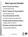
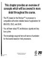
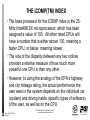
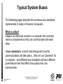
PC Architecture for
Technicians: Level-1
Systems Manufacturing Training &
Employee Development
Copyright © 1996 Intel Corp.
PC Architecture For Technicians Level-1
Rev. 1.0 Sys MFG T/ED
4/25/2003
Technical Excellence Development Series
Ch 1- Page 1
Chapter 1
Introduction
PC Architecture for
Technicians: Level-1
Systems Manufacturing Training
and Employee Development
Copyright © 1996 Intel Corp.
PC Architecture For Technicians Level-1
Rev. 1.0 Sys MFG T/ED
4/25/2003
Technical Excellence Development Series
Ch 1- Page 2
Trademark notice
n
The following are trademarks of Intel Corporation
3
n
iCOMP(R), IntelDX4, i386, i486, IntelDX2, Intel386, Intel486, i486,
Pentium(R), 8088, 8086, 80286, 80386, 80486, 82288, 8042, 8259,
8254, 8327-A
The following are trademarks of International Business Machines
Corporation
3
IBM, IBM PC, PC/XT, PC/AT, PS/2, Micro Channel, VGA, CGA, EGA,
MDA, PC-DOS and OS/2
n
MS-DOS(R) and Windows are trademarks of Microsoft Corporation.
n
UNIX is a registered trademark of UNIX Systems Laboratories.
n
TRISTATE is a trademark of National Semiconductor Corporation.
n
All other product names not listed here but mentioned in this material may
be trademarks and/or registered trademarks of their respective
companies.
PC Architecture For Technicians Level-1
Rev. 1.0 Sys MFG T/ED
4/25/2003
Technical Excellence Development Series
Ch 1- Page 3
Where to get more information
l
The Indispensable PC Hardware Book (Messmer)
Addison-Wesley (ISBN 0-201-87697-3)
n
l
ISA System Architecture (Shanley & Anderson)
Mindshare (ISBN 0-201-40996-8)
n
l
The Personal Computer from the Inside Out
Addison-Wesley (ISBN 0-201-62646-2)
n
l
The Peter Norton PC Programmer’s Bible
Microsoft Press (ISBN 1-55615-555-7)
n
l
The Indispensable Pentium™ Book (Messmer)
Addison-Wesley (ISBN 0-201-87727-9)
n
l
Pentium™ Processor System Architecture
Mindshare (ISBN 1-881609-07-3)
n
PC Architecture For Technicians Level-1
Rev. 1.0 Sys MFG T/ED
4/25/2003
Technical Excellence Development Series
Ch 1- Page 4
Where to get more information
l
Pentium™ Processor User’s Manual
Intel Order Number 241428
n
l
Pentium™ Architecture & Programming Manual
Intel Order Number 241430
n
l
PCI Local Bus Specification (PCI SIG)
PCI Special Interest Group (CC:Mail PCI_SIG)
n
l
PCI System Architecture (Shanley & Anderson)
Mindshare (ISBN 0-201-40993-3)
n
l
PCI Hardware and Software (Solari & Willse)
Annabooks (ISBN 0-929392-28-0)
n
PC Architecture For Technicians Level-1
Rev. 1.0 Sys MFG T/ED
4/25/2003
Technical Excellence Development Series
Ch 1- Page 5
This chapter provides an overview of
concepts which will be covered in more
detail throughout the course.
l
The PC based on the Pentium™ is processor is
compatible with entire installed base of applications for
MS-DOS, OS/2, and UNIX.
l
You will learn about PC architecture, signals and key
bus cycles.
l
The knowledge acquired here will serve a foundation
for the boards based on Intel processors.
PC Architecture For Technicians Level-1
Rev. 1.0 Sys MFG T/ED
4/25/2003
Technical Excellence Development Series
Ch 1- Page 6
OBJECTIVES: At the end of this section,
the student will be able to do the following:
l
Discuss the iCOMP(TM) INDEX
l
Discuss System Buses.
l
Describe a simple Microprocessor System
l
Describe the System Board & Peripheral chips.
l
Discuss Microprocessor Buses & simple bus cycles.
l
Discuss fetching of initial instructions after CPU is
reset.
PC Architecture For Technicians Level-1
Rev. 1.0 Sys MFG T/ED
4/25/2003
Technical Excellence Development Series
Ch 1- Page 7
THE iCOMP(TM) INDEX
Intel Family Comparison
Intel iCOMP Index
386 DX 25
486 SX25
DX2 66
DX4 100
Pentium 60
Pentium 66
Pentium 90
Pentium 100
0
200
400
600
800
1000
Examples: Pentium 510/60; 735/90; 815/100
PC Architecture For Technicians Level-1
Rev. 1.0 Sys MFG T/ED
4/25/2003
Technical Excellence Development Series
Ch 1- Page 8
THE iCOMP(TM) INDEX
l
A NEW WAY TO COMPARE CPU PERFORMANCE
l
iCOMP (Intel COmparative Microprocessor Performance).
l
The iCOMP index is a simple numerical index of relative
performance for making straightforward comparisons of Intel
CPU power. It provides consumers with useful information
when they make a PC purchase. It is intended to supplement,
not replace benchmarks.
l
The iCOMP formula was designed to reflect the full capabilities
of a CPU--those which are executed not only by today's
desktop systems and software applications, but the software
expected to be in use throughout the three to five year average
life of a system bought today.
l
It is an index that reflects the relative performance of one Intel
microprocessor to another, not system performance.
PC Architecture For Technicians Level-1
Rev. 1.0 Sys MFG T/ED
4/25/2003
Technical Excellence Development Series
Ch 1- Page 9
THE iCOMP(TM) INDEX
l
The base processor for the iCOMP index is the 25MHz Intel486 SX microprocessor, which has been
assigned a value of 100. All other rated CPUs will
have a number that is either above 100, meaning a
faster CPU, or below, meaning slower.
l
The size of the disparity between any two indices
provides a relative measure of how much more
powerful one CPU is than any other.
l
However, to using the analogy of the EPA's highway
and city mileage rating, the actual performance the
user sees in the system depends on the individual car
(system) and driving habits (specific types of software)
of the user, as well as on the CPU.
PC Architecture For Technicians Level-1
Rev. 1.0 Sys MFG T/ED
4/25/2003
Technical Excellence Development Series
Ch 1- Page 10
Typical
System
Buses
PC Architecture For Technicians Level-1
Rev. 1.0 Sys MFG T/ED
4/25/2003
Technical Excellence Development Series
Ch 1- Page 11
Typical System Buses
The following pages describe the numerous bus standards
implemented in today’s Personal Computers.
What is a Bus?
A bus is an electrical conduit in a computer that connects
various components so they can communicate with each
other.
A bus standard is a set of rules that govern how the
communications will take place....think of it as “grammar” for
a computer. And different bus standards will have different
grammatical rules that affect how quickly they can
communicate.
PC Architecture For Technicians Level-1
Rev. 1.0 Sys MFG T/ED
4/25/2003
Technical Excellence Development Series
Ch 1- Page 12
Typical System Buses
r
r
r
“Bridges” isolate buses electrically and logically.
Higher performance functions on PCI bus.
Low performance functions on ISA or EISA bus.
Cache Memory
Subsystem
X86 CPU
Host Bus
DRAM Subsystem
PCI Bridge/
Memory
Controller
PCI Add-in Slots
PCI Local Bus
ISA Bus
ISA Add-in Slots
Bridge
ISA Bus
PC Architecture For Technicians Level-1
Rev. 1.0 Sys MFG T/ED
4/25/2003
Technical Excellence Development Series
Ch 1- Page 13
Introduction - Bus Standards
ISA
When the PC was introduced in the early 1980’s, the Industry
Standard Architecture (ISA) bus was used. As the PC’s
popularity spread and “clones” appeared, the ISA bus was
always used for compatibility. It is 16-bits wide at 8MHz, and
is fully compatible with all PC software. An ISA system will
accept ISA add-in cards It is found in most PCs.
Memory
CPU
ISA Bus
Keyboard, Disks,
Other Elements
ISA
Slots
ISA Bus: Standard System
PC Architecture For Technicians Level-1
Rev. 1.0 Sys MFG T/ED
4/25/2003
Technical Excellence Development Series
Page 2
Ch 1- Page 14
Introduction - Bus Standards
EISA
The Enhanced ISA, or EISA bus, is faster than ISA (32-bits
@ 8MHz), and is fully compatible with ISA and all PC
software. An EISA bus will give better overall performance
to a computer system, and will accept ISA & EISA cards.
It is typically used in servers, workstations and high-end
PCs.
Memory
CPU
EISA Bus
Keyboard, Disks,
Other Elements
EISA
Slots
EISA Bus: Improved overall performance
PC Architecture For Technicians Level-1
Rev. 1.0 Sys MFG T/ED
4/25/2003
Technical Excellence Development Series
Ch 1- Page 15
Introduction - Bus Standards
VL / VESA Local Bus: In 1992, the VL Local Bus began
to appear and was mainly used to increase the graphics
performance. It is used in conjunction with an ISA bus.
Since the VL Bus is attached directly to the CPU, both
must run at the same speed. For electrical reasons, the
VL Bus can only support 2 add-in cards at 33MHz, and
none at 50MHz.
Memory
CPU
VL Bus
VL Slots
EISA or ISA Bus
Keyboard, Disks,
Other Elements
ISA or EISA
Expansion Slots
PC Architecture For Technicians Level-1
Rev. 1.0 Sys MFG T/ED
4/25/2003
Technical Excellence Development Series
Ch 1- Page 16
Introduction - Bus Standards
PCI Bus: Like the VL Bus, PCI will improve graphics
performance, but will support other components as well
(network, hard drive, etc.). Since it is not directly
connected to the CPU, it sheds the electrical limitations of
the VL bus and will accept multiple PCI-bus add-in cards.
Memory
CPU
PCI Bus
PCI Slots
Disk, Network
etc.
EISA or ISA Bus
Keyboard, Disks,
Other Elements
ISA or EISA
Expansion Slots
PC Architecture For Technicians Level-1
Rev. 1.0 Sys MFG T/ED
4/25/2003
Technical Excellence Development Series
Page 3
Ch 1- Page 17
Simple
Microprocessor
Systems
PC Architecture For Technicians Level-1
Rev. 1.0 Sys MFG T/ED
4/25/2003
Technical Excellence Development Series
Ch 1- Page 18
Simple
Microprocessor
Systems
CPU
RAM
ROM
BUS
I/O
KEYBOARD
I/O
CONSOLE
DISPLAY
I/O
DISK
I/O
PRINTER
PC Architecture For Technicians Level-1
Rev. 1.0 Sys MFG T/ED
4/25/2003
Technical Excellence Development Series
Ch 1- Page 19
Simple Microprocessor Systems
What are the needs of a simple microprocessor
system?
l
A microprocessor
l
Memory for program and data storage
RAM--Random-Access Memory comes in two main
types:
n
DRAM--dynamic RAM; needs periodic refreshing
3
STATIC--fast, expensive; needs no refreshing
3
RAM does not retain the stored code and data when the
computer is turned off. RAM is used to store the
operating system and user programs.
n
PC Architecture For Technicians Level-1
Rev. 1.0 Sys MFG T/ED
4/25/2003
Technical Excellence Development Series
Ch 1- Page 20
Simple Microprocessor Systems
What are the needs of a simple microprocessor
system? (Cont.)
l
ROM--Read-only memory-available in many main types
3
PROMS--cannot be reprogrammed, but are cheaper
3
EPROMS--can be erased and reprogrammed (UV)
3
EEPROMS--can be erased and reprogrammed (byte at a time)
3
FLASH-- can be erased and reprogrammed (all cells at once)
ROM retains the stored code and data when the
computer is turned off. ROM usually contains the
following:
n
POST--Power-On-Self-Test
3
BIOS--Basic Input Output System. Low level interface to
devices (Low level I/O drivers and services).
3
PC Architecture For Technicians Level-1
Rev. 1.0 Sys MFG T/ED
4/25/2003
Technical Excellence Development Series
Ch 1- Page 21
Simple Microprocessor Systems
What are the needs of a simple microprocessor
system? (Cont.)
l
I/O devices to provide user interaction with the
computer. Typical I/O devices are these:
keyboard
n
display unit
n
file storage (floppy and hard disks)
n
printer
n
modems
n
PC Architecture For Technicians Level-1
Rev. 1.0 Sys MFG T/ED
4/25/2003
Technical Excellence Development Series
Ch 1- Page 22
Statistical Comparison
PCAT
Compatibility
Standard
CPU
8088
80286
MEM SIZE
1 MEG
1 6 MEG*
NA
1 GIG
8
16
32
32
64
16
16
32
32
32
4
4
6
6
6
80287
80387
REG SIZE
# SEG. REGS
MATH
BUS SPEED (MHz)
PAGING
ON CHIP
CACHE
8087
4.77, 10
8, 12
32
Pentium
20
D-BUS
32
80486
Addr -BUS
VIRTUAL
SIZE
24
80386
4 GIG *
4 GIG*
64 TERA
64 TERA
25, 33
On Chip
33, 50
32
4 GIG*
64 TERA
On Chip
50, 60, 66
NO
NO
YES
YES
YES
NO
NO
NO
YES
YES
* Protected Mode
PC Architecture For Technicians Level-1
Rev. 1.0 Sys MFG T/ED
4/25/2003
Technical Excellence Development Series
Ch 1- Page 23
System Board
Overview
PC Architecture For Technicians Level-1
Rev. 1.0 Sys MFG T/ED
4/25/2003
Technical Excellence Development Series
Ch 1- Page 24
PC/AT System Board Overview
ADAPTER CARDS
ON ISA BUS
SYSTEM BOARD
POWER SUPPLY
DISKS
DISPLAY
SYSTEM
UNIT
KEYBOARD
PC Architecture For Technicians Level-1
Rev. 1.0 Sys MFG T/ED
4/25/2003
Technical Excellence Development Series
Ch 1- Page 25
System Board Overview
l
The emphasis in this course is an Intel system board.
l
The Intel system board is compatible with the original 8 MHz
IBM PC/AT.
l
We will use the term "PC/AT" to refer to a "generic" computer
when we are not discussing specific implementations.
The following items define a PC/AT:
n
A system board containing an Intel 80286, 80386, 80486 or
Pentium microprocessor, plus peripheral chips compatible with the
original IBM PC/AT.
»(The PC/XT used an Intel 8088.)
n
System board "adapter card slots" (ISA) compatible with those on
the original IBM PC/AT.
n
Disk drives providing IBM PC/AT compatibility (diskette and fixed
disks).
PC Architecture For Technicians Level-1
Rev. 1.0 Sys MFG T/ED
4/25/2003
Technical Excellence Development Series
Ch 1- Page 26
System Board Overview
l
The following items define a PC/AT: (Cont.)
A power supply (+5v, -5v, +12v, -12v).
n
A compatible keyboard.
n
A display adapter and monitor. The basic types are
monochrome, CGA, EGA, and VGA.
n
The system board must contain an IBM PC/AT compatible
BIOS. Examples are AMI, Award and Phoenix BIOS.
n
Many applications directly access low-level hardware and
BIOS functions. This leads to requirement that the board
must contain an IBM PC/AT compatible BIOS.
3
In addition to connecting the above components, a PC/AT
must be able to run MS DOS or PC DOS applications.
n
PC Architecture For Technicians Level-1
Rev. 1.0 Sys MFG T/ED
4/25/2003
Technical Excellence Development Series
Ch 1- Page 27
System Board Overview
l
Add-on products typically come with software
drivers and adapter cards. Examples include:
Printers
n
Diskette and fixed disk controllers and drives
n
Communications (RS232, LANS, GPIB, Modems)
n
Mice
n
l
NOTE: IBM has published Technical References
for the IBM PC, PC/XT, and PC/AT.
3
The references include circuit diagrams and BIOS listings and
provide the information necessary for the PC industry to produce
imitations.
3
The references were not complete, as they didn't adequately
define the (ISA) bus signals.
PC Architecture For Technicians Level-1
Rev. 1.0 Sys MFG T/ED
4/25/2003
Technical Excellence Development Series
Ch 1- Page 28
THE SYSTEM BOARD IN DETAIL
l
MICROPROCESSOR
The original PC/AT contained the following chips which
formed the heart of the system board:
n
3
an Intel 80286 microprocessor (6 then 8 MHz)
3
an Intel 82284 clock, reset, and ready chip
3
an Intel 82288 bus controller chip
3
a socket for the Intel 80287 math coprocessor
Current Intel boards have contain a microprocessor and a
ChipSet which incorporates the functions of the the Bus &
Memory Controllers as well as most of the peripheral chips.
n
PC Architecture For Technicians Level-1
Rev. 1.0 Sys MFG T/ED
4/25/2003
Technical Excellence Development Series
Ch 1- Page 29
THE SYSTEM BOARD IN DETAIL
l
BUSES
On the original PC/AT, several "buses" were created from the
local 286 bus. Each bus, including the 286 local bus, has
three parts (address, data, control)
n
Current Intel boards have buses that contain the three
basic parts (address, data, control).
n
l
SYSTEM BOARD RAM MEMORY
The system board of the IBM PC/AT contained up to 512K
bytes of dynamic RAM. Adapters could be added to bring the
memory to 640K bytes and above.
n
Current Intel boards contain upwards of 128M on the system
board (using SIMM or DIMM modules).
n
PC Architecture For Technicians Level-1
Rev. 1.0 Sys MFG T/ED
4/25/2003
Technical Excellence Development Series
Ch 1- Page 30
XT, AT System Board Peripherals
Today's Personal Computers are COMPATIBLE with the PC/AT
XT
AT
CPU
8088
80286
80386
MATH
8087
80287
80387
TIMER
(pit)
8253
8254
DMA
8237
2 - 8237s
INTERRUPTS
(pic)
8259
2 - 8259s
DIGITAL
I/O
8255
LOGIC
8042 Micro controller
RAM
640K
16MEG
ROM
48K
64K (128K)
NONE
CLOCK CHIP W/ CMOS RAM BATTERY BACKUP
REAL-TIME
CLOCK
80486 & Pentium
on Chip
Up to 4 GIG
PC Architecture For Technicians Level-1
Rev. 1.0 Sys MFG T/ED
4/25/2003
Technical Excellence Development Series
Ch 1- Page 31
XT, AT System Board Peripherals
l
l
SYSTEM BOARD PERIPHERAL CHIPS: These will be
described in detail in this course.
n
An Intel 8254 Programmable Interval Timers (PIT).
n
Two Intel 8259A Programmable Interrupt Controller chips (PIC).
n
An Intel 8042 (8742) MICROCONTROLLER to provide digital I/O and to interface
with the keyboard.
n
A real-time clock chip that provides time, and 64 bytes of CMOS RAM for
configuration information. The clock chip is backed up with a battery.
n
Two Intel 8237-5 DMA Controller chips.
n
A 74LS612 latch to provide page information during DMA transfers.
n
A DRAM Refresh Controller.
Remaining system board features (not covered in this course)
n
Two 82510 (or compatible) UARTS providing two COM ports.
n
Circuitry to support a parallel printer port.
n
A speaker for beeping.
PC Architecture For Technicians Level-1
Rev. 1.0 Sys MFG T/ED
4/25/2003
Technical Excellence Development Series
Ch 1- Page 32
System Board Component Layout
COM2
PCI
ARBITER
PAL
BAT
1
Parallel
O
M
K
COM1
VID override
CPU Fan conn
CPU
SOCKET
MIC
SIMM
SIMM
SIMM
SIMM
PCI EXPANSION SLOT
PCI EXPANSION SLOT
PCI EXPANSION SLOT
PCI EXPANSION SLOT
ISA EXPANSION SLOT
ISA EXPANSION SLOT
ISA EXPANSION SLOT
MIC
OMC
DP
Power
MIC
PIIX
Pin 1
MIC
OMC
DC
FLASH
ROM
3
27
OPB
SUPER
I/O
PCI IDE Connector
PCI IDE Connector
1
25
JUMPER BLOCK
SPKR
Floppy Connector
Front panel
connector
PC Architecture For Technicians Level-1
Rev. 1.0 Sys MFG T/ED
4/25/2003
Technical Excellence Development Series
Ch 1- Page 33
Microprocessor
Buses & Simple
Bus Cycles
PC Architecture For Technicians Level-1
Rev. 1.0 Sys MFG T/ED
4/25/2003
Technical Excellence Development Series
Ch 1- Page 34
CPU Signals Required for operation
Pentium CPU
Power
Address Bus
A31 - A3
Ground
RESET
Byte Enables
BE7# - 0#
CLK
Pentium
Data Bus
D63 - D0
AHOLD
BRDY#
ADS#
W/R#
M/IO#
PC Architecture For Technicians Level-1
Rev. 1.0 Sys MFG T/ED
4/25/2003
Technical Excellence Development Series
Ch 1- Page 35
CPU Signals Required for operation
l
Power and Ground signals on multiple pins.
5.0v for P5, 3.3v for P54C
n
l
Processor RESET (input):
l
Processor CLOCK (input): Often 50, 60, or 66
MHz depending on design.
l
AHOLD (input) not active: Used to disable the
address bus for alternate bus master (e.g.
DMA) cache snooping.
PC Architecture For Technicians Level-1
Rev. 1.0 Sys MFG T/ED
4/25/2003
Technical Excellence Development Series
Ch 1- Page 36
Microprocessor Buses
ADDRESS
CPU
MEM RD
MEM WR
IO RD
IO WR
DATA
CONTROL
MEMORY
I/O
PC Architecture For Technicians Level-1
Rev. 1.0 Sys MFG T/ED
4/25/2003
Technical Excellence Development Series
Ch 1- Page 37
MICROPROCESSOR BUSES
The microprocessor uses several buses to
communicate with memory and I/O.
l
l
In general, there are three buses:
Address
n
Data
n
Control
n
PC Architecture For Technicians Level-1
Rev. 1.0 Sys MFG T/ED
4/25/2003
Technical Excellence Development Series
Ch 1- Page 38
MICROPROCESSOR BUSES
l
Address bus: The microprocessor provides an
address to the memory & I/O chips.
The number of address lines determines the amount of
memory supported by the processor.
n
A31:A3 Address bus lines determines where in the 4GB
memory space or 64K IO space the CPU is accessing.
n
BE7#:BEO# (outputs): Byte enable lines to enable each
of the 8 bytes in the 64-bit data path.
n
In effect a decode of the address lines A2-A0 which the
Pentium does not generate.
3
Which lines go active depends on the address, and
whether the cycle requires a byte, word, double word or
quad word.
3
PC Architecture For Technicians Level-1
Rev. 1.0 Sys MFG T/ED
4/25/2003
Technical Excellence Development Series
Ch 1- Page 39
Bus Description
FFFFFFFFH
Physical Memory
Space
FFFFFFF8H
PHYSICAL
MEMORY
4GB
00000007H
00000000H
FFFFFFFFH
FFFFFFF8H
00000007H
00000000H
BE7# BE6# BE5# BE4# BE3# BE2# BE1# BE0#
64-BIT Wide Memory
Organization
PC Architecture For Technicians Level-1
Rev. 1.0 Sys MFG T/ED
4/25/2003
Technical Excellence Development Series
Ch 1- Page 40
Bus Description
l
I/O Address Space is limited to 64 Kbytes (0000H-FFFFH).
l
This limit is imposed by a 16 bit CPU Register.
n
A 16 bit register can store up to FFFFH (1111 1111 1111 1111 y).
Not
Accessible
0000FFFFH
64 KByte
00000003H
0000FFFCH
00000000H
I/O Space
PC Architecture For Technicians Level-1
Rev. 1.0 Sys MFG T/ED
4/25/2003
Technical Excellence Development Series
Ch 1- Page 41
MICROPROCESSOR BUSES
Data bus: The data bus provides a path for data to flow.
l
The data can flow to/ from the microprocessor during a
memory or I/O operation.
Provides the propagation path in both directions.
n
l
D63:DO (bi-directional): The 64-bit data path to or
from the processor.
The signal W/R# distinguishes direction.
n
l
Parity DP7:DPO (bi-directional): Pentium uses EVEN
parity bits on a per-byte basis.
Parity signals: Output on writes, Input on reads.
n
3
Not supported on all systems.
PC Architecture For Technicians Level-1
Rev. 1.0 Sys MFG T/ED
4/25/2003
Technical Excellence Development Series
Ch 1- Page 42
MICROPROCESSOR BUSES
Control bus: The control bus is used by the microprocessor
to tell the memory and I/O chips what the microprocessor is
doing.
l
Typical control bus signals are these:
M/IO# (output): Defines if the bus cycle is a Memory access
or an IO Port access.
n
D/C# (output): Defines if the bus cycle is Data or Code for
Memory access.
n
W/R# (output): Indicates if bus cycle is a Write or a Read
operation.
n
Cache#. (output): Processor indication of internal
cacheability. Cache# and Ken# are used together to
determine if a read will be turned into a linefill. (Burst cycle).
n
PC Architecture For Technicians Level-1
Rev. 1.0 Sys MFG T/ED
4/25/2003
Technical Excellence Development Series
Ch 1- Page 43
MICROPROCESSOR BUSES
l
CONTROL BUS (Cont)
l
ADS# (output): Signals that the processor is
beginning a bus cycle.
From power-on the ADS# signal should be asserted
periodically when bus cycles are running.
n
l
BRDY# (input): This signal ends the current bus cycle
(low) and is used to extend bus cycles (high) to allow
slow devices extra time.
If LOW, this signal ends the current bus cycle and the next
bus cycle can begin.
n
If HIGH the Pentium is prevented from continuing processing
and wait states are added to allow slow devices extra time.
n
PC Architecture For Technicians Level-1
Rev. 1.0 Sys MFG T/ED
4/25/2003
Technical Excellence Development Series
Ch 1- Page 44
Ready Logic State
Machine Example
BRDY#
Zero WS
ADS#
Cache Read
IOCHRDY
0=Add Wait
States for
ISA BUS
TW
TW= Time Wait
TW
DRAM-Read
TW
TW
ISA Bus Read
Access /EPROMs
TW
TW
TW
TW
TW
PC Architecture For Technicians Level-1
Rev. 1.0 Sys MFG T/ED
4/25/2003
Technical Excellence Development Series
Ch 1- Page 45
Microprocessor Bus Cycles
l
A BUS CYCLE begins with the Processor driving an
address and control signals and asserting ADS#.
l
A BUS CYCLE ends when the last BRDY# is returned
to the Processor.
l
A BUS CYCLE may have 1 or 4 data transfers.
A SINGLE Cycle transfer is 64 bits maximum [8 bytes].
n
A BURST Cycle transfer is 256 bits (4*64) [32 bytes]
n
l
The following table lists all the bus cycles that will be
generated by the Pentium microprocessor
(From Table 6-10 in Pentium manual)
n
PC Architecture For Technicians Level-1
Rev. 1.0 Sys MFG T/ED
4/25/2003
Technical Excellence Development Series
Ch 1- Page 46
Bus Cycle Definition
M /IO#
0
D/C#
0
W/R#
0
Cache#
1
Ken#
x
0
0
0
1
1
0
1
1
x
x
0
1
1
1
x
1
0
0
1
x
1
0
0
x
1
1
0
0
0
0
1
0
1
x
x
1
1
0
1
x
1
1
0
x
1
1
1
0
0
0
1
1
1
1
x
Cycle Description
No. of Transfers
Interrupt Acknowledge
(2 locked cycles)
Special Cycle
1 transfer each cycle
I/O Read , 32-bits or less
Non Cacheable
I/O Write , 32-bits or less
Non Cacheable
Code Read, 64-bits,
Non Cacheable
Code Read, 64-bits,
Non Cacheable
Code Read , 256-bit burst
Line Fill
Intel Reserved (will not be
driven by the Pentium™
processor).
Memory Read, 64 bit or less,
Non Cacheable
Memory Read, 64 bit or less,
Non Cacheable
Memory Read, 256 bit bursrt
Line Fill
Memory Write, 64 bit or less
Non Cacheable
256 bit Burst Write back
1
1
1
1
1
4
n/a
1
1
4
1
1
1
1
0
x
4
*Cache# will not be asserted for any cycle in which M/IO# is driven low, or for any cycle in which
PCD is driven high.
PC Architecture For Technicians Level-1
Rev. 1.0 Sys MFG T/ED
4/25/2003
Technical Excellence Development Series
Ch 1- Page 47
GENERIC DECODE LOGIC
l
The system board contains some logic to decode the
BUS CYCLE DEFINITIONS of the CPU.
l
The BUS CYCLE DEFINITIONS from the CPU are
VALID when ADS# is asserted (Logic 0).
l
The drawing shows an example of logic that could be
used to decode the BUS CYCLE DEFINITIONS.
l
The signals generated by the GENERIC DECODE
LOGIC would be used by the System Board to
generate signals such as I/O chip selects and DRAM &
PROM output enables.
PC Architecture For Technicians Level-1
Rev. 1.0 Sys MFG T/ED
4/25/2003
Technical Excellence Development Series
Ch 1- Page 48
GENERIC DECODE LOGIC
M/IO#
D
D
D
D/C#
Q
Q
Q
INTA
W/R#
ADS#
486 / P5
SPECIAL
IOR
e.g.
I/O WR @ Addr 43H
0
1
1
IOW
FETCH
486 / P5
INVALID
MEMR
MEMW
PC Architecture For Technicians Level-1
Rev. 1.0 Sys MFG T/ED
4/25/2003
Technical Excellence Development Series
Ch 1- Page 49
Microprocessor Single Bus Cycle
MEMORY WRITE & READ WITH WAIT STATES
T1
T2
T2
Ti
WAIT
STATE
IDLE
STATE
T1
T2
T2
T2
Ti
CLK
ADS#
A31-A3
ADDR
BE7# - 0
Byte
Enables
W/R#
WAIT
STATE
WAIT
STATE
IDLE
STATE
ADDR
Byte
Enables
WRITE
READ
CACHE#
BRDY#
D63-D0
DATA
DATA
FROM CPU
PC Architecture For Technicians Level-1
Rev. 1.0 Sys MFG T/ED
4/25/2003
Technical Excellence Development Series
TO
CPU
Ch 1- Page 50
Basic Burst Read Cycle
CYCLE
1
T1
T2
CYCLE
2
CYCLE
3
CYCLE
4
T2
T2
T2
Ti
Ti
Ti
Ti
HCLK
ADS#
A31-A3
BE7:0
IDLE
STATE
IDLE
STATE
IDLE
STATE
ADDR
CACHE#
W/R#
READ
KEN#
BRDY#
D63-D0
DATA
DATA
DATA
DATA
TO
CPU
TO
CPU
TO
CPU
TO
CPU
PC Architecture For Technicians Level-1
Rev. 1.0 Sys MFG T/ED
4/25/2003
Technical Excellence Development Series
Ch 1- Page 51
Fetching the
Initial
Instructions
PC Architecture For Technicians Level-1
Rev. 1.0 Sys MFG T/ED
4/25/2003
Technical Excellence Development Series
Ch 1- Page 52
ACCESSING THE BIOS
F
F
F
F
F
F
31 30 29 28 27 26 25 24 23 22 21 20 19 18 17 16 15 14 13 12 11 10 9 8
F
0
7 6 5 4 3 2 1 0
11111111 1111111111111111 11110000
A15
NONVOLATILE
MEMORY
Flash
BIOS
A0
FFFFFFF0
D7
D0
CS#
OE#
MEMR
From
Mem-Code-Read
Bus Cycle Definition
000FFFF0
0
SHADOW BIOS
ENABLE BIT
1 = Shadowed:
Disable ROM Chip Select
PC Architecture For Technicians Level-1
Rev. 1.0 Sys MFG T/ED
4/25/2003
Technical Excellence Development Series
Ch 1- Page 53
ACCESSING THE FLASH BIOS
l
The Chip Select for the BIOS is the result of
decoding the Reset Vector.
The CPU Address at Reset is the Reset Vector.
n
Address = FFFFFFF0 physical. The physical address is
3
the output on the CPU address bus.
The Upper AND GATE will generate a CS# for address
FFFFXXXXp
n
l
The Mem Code Read bus cycle definition causes the
Flash BIOS Output Enable.
The first bus cycle definition is a Code Fetch
n
3
(Memory, Code, Read)
PC Architecture For Technicians Level-1
Rev. 1.0 Sys MFG T/ED
4/25/2003
Technical Excellence Development Series
Ch 1- Page 54
Fetching the Initial Instructions
l
The CPU is forced into a known condition at RESET.
The address is set to the Reset Vector (FFFFFFF0 physical)
n
3
CPU internal registers generate this address.
The first bus cycle definition is a Code Fetch.
n
l
The CPU will FETCH the first instructions from the
BIOS.
The ROM BIOS is chip selected as a result of the Reset
Vector address (FFFFFFF0)
n
The Flash BIOS output enable results from the Mem Code
Read bus cycle definition.
n
The ROM data is accepted by the CPU when BRDY# is
asserted.
n
PC Architecture For Technicians Level-1
Rev. 1.0 Sys MFG T/ED
4/25/2003
Technical Excellence Development Series
Ch 1- Page 55
Fetching the Initial Instructions
l
The CPU DECODES the ROM BIOS instructions.
The HEX BYTES (machine code) stored in the BIOS are
decoded by the CPU into instructions.
n
l
The first instruction decoded is a FAR JUMP to
000FEO5Bp
The F0000p-FFFFFp range is the 1 MB COMPATIBLE
PC/AT address range accessed in REAL MODE.
n
BIOS Chip Select now results from decoding 000FEO5Bp.
n
The Lower AND GATE will generate a CS# for an address in
the 000FXXXXp range (000F0000p - 000FFFFFp).
n
l
POST will now EXECUTE in the F0000p-FFFFFp
range
PC Architecture For Technicians Level-1
Rev. 1.0 Sys MFG T/ED
4/25/2003
Technical Excellence Development Series
Ch 1- Page 56
Fetching the Initial Instructions
l
The CPU executes the Code fetched from the ROM
and the POST (Power On Self Test) is executed.
POST detects, checks, & initializes installed components on
the system board.
n
POST writes a CODE to I/O Port 80 at the start of each new
POST test.
n
POST normally stops on critical Failures.
n
3
The LAST POST CODE written to Port 80 is an indication of the
failure.
If everything is OK, POST gives control to a Bootstrap Loader
to load an Operating System via INT 19H.
n
l
The majority of failures will occur before POST has
completed and gives control to a Bootstrap Loader .
PC Architecture For Technicians Level-1
Rev. 1.0 Sys MFG T/ED
4/25/2003
Technical Excellence Development Series
Ch 1- Page 57
SUMMARY
WE HAVE DISCUSSED THE FOLLOWING:
l THE iCOMP(TM) INDEX
l System Buses.
l Simple Microprocessor Systems
l The System Board & Peripheral chips.
l Microprocessor Buses & simple bus cycles.
l Fetching instructions after CPU is reset.
PC Architecture For Technicians Level-1
Rev. 1.0 Sys MFG T/ED
4/25/2003
Technical Excellence Development Series
Ch 1- Page 58