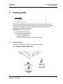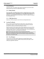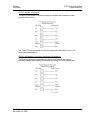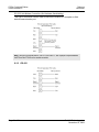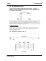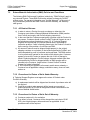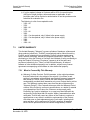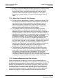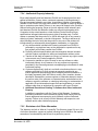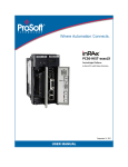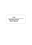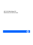
1
PC56 ControlLogix Platform In-Rack Industrial PC November 18, 2009 USER MANUAL PC56 Modules WARNING - EXPLOSION HAZARD - DO NOT DISCONNECT EQUIPMENT UNLESS POWER HAS BEEN SWITCHED OFF OR THE AREA IS KNOWN TO BE NON-HAZARDOUS. AVERTISSEMENT - RISQUE D'EXPLOSION - AVANT DE DÉCONNECTER L'EQUIPMENT, COUPER LE COURANT OU S'ASSURER QUE L'EMPLACEMENT EST DÉSIGNÉ NON DANGEREUX. Temp Code T5 II 3 G Ex nA IIC T5 X 0° C <= Ta <= 60° C II - Equipment intended for above ground use (not for use in mines). 3 - Category 3 equipment, investigated for normal operation only. G - Equipment protected against explosive gasses. Warnings ATEX Warnings and Conditions of Safe Usage: Power, Input, and Output (I/O) wiring must be in accordance with the authority having jurisdiction A B C D Warning - Explosion Hazard - When in hazardous locations, turn off power before replacing or wiring modules. Warning - Explosion Hazard - Do not disconnect equipment unless power has been switched off or the area is known to be non-hazardous. These products are intended to be mounted in an IP54 enclosure. The devices shall provide external means to prevent the rated voltage being exceeded by transient disturbances of more than 40%. This device must be used only with ATEX certified backplanes. DO NOT OPEN WHEN ENERGIZED. Electrical Ratings Backplane Current Load on PC56: 1A @ 5 V DC Backplane Current Load on IDE: 1A @ 5 V DC Operating Temperature: 0 to 60°C (32 to 140°F) Storage Temperature: -40 to 85°C (-40 to 185°F) Shock: 30g Operational; 50g non-operational; Vibration: 5 g from 10 to 150 Hz Relative Humidity 5% to 95% (non-condensing) All phase conductor sizes must be at least 1.3 mm(squared) and all earth ground conductors must be at least 4mm(squared). Markings: CSA/cUL C22.2 No. 213-1987 CSA CB Certified IEC61010 ATEX EN60079-0 Category 3, Zone 2 EN60079-15 243333 PC56™ Battery Warning PC56 CMOS BIOS settings are protected by a rechargeable battery during power-down situations. The battery must be fully charged before you change BIOS settings. You must keep the unit powered up for a full 20 hours in order to obtain full charge capacity. If the battery is not fully charged, changes to BIOS settings may be lost when the PC56 is removed from its power source. In this situation, the PC56 reverts to its default BIOS settings when power is reapplied. If the battery is discharged, or the battery enable jumper is removed, the BAT LED will be illuminated red. A fully charged battery should maintain the BIOS settings for 15 days without power. Your Feedback Please We always want you to feel that you made the right decision to use our products. If you have suggestions, comments, compliments or complaints about the product, documentation, or support, please write or call us. ProSoft Technology 5201 Truxtun Ave., 3rd Floor Bakersfield, CA 93309 +1 (661) 716-5100 +1 (661) 716-5101 (Fax) www.prosoft-technology.com [email protected] Copyright © ProSoft Technology, Inc. 2009. All Rights Reserved. PC56 User Manual November 18, 2009 ProSoft Technology ®, ProLinx ®, inRAx ®, ProTalk®, and RadioLinx ® are Registered Trademarks of ProSoft Technology, Inc. All other brand or product names are or may be trademarks of, and are used to identify products and services of, their respective owners. ProSoft Technology® Product Documentation In an effort to conserve paper, ProSoft Technology no longer includes printed manuals with our product shipments. User Manuals, Datasheets, Sample Ladder Files, and Configuration Files are provided on the enclosed CD-ROM, and are available at no charge from our web site: www.prosoft-technology.com Printed documentation is available for purchase. Contact ProSoft Technology for pricing and availability. North America: +1.661.716.5100 Asia Pacific: +603.7724.2080 Europe, Middle East, Africa: +33 (0) 5.3436.87.20 Latin America: +1.281.298.9109 Contents User Manual PC56 ♦ ControlLogix Platform In-Rack Industrial PC Contents PC56 Modules..................................................................................................................................... 2 Warnings ............................................................................................................................................. 2 PC56™ Battery Warning..................................................................................................................... 3 Your Feedback Please........................................................................................................................ 3 ProSoft Technology® Product Documentation....................................................................................3 1 Using This Manual 1.1 1.2 1.3 2 Who Should Use This Manual...................................................................................7 Reference Material .................................................................................................... 8 Product Specifications...............................................................................................8 Introducing PC56 2.1 3 3.1 3.2 4.1 4.2 5.1 19 FAQ .........................................................................................................................19 Reference 6.1 6.2 7 17 Overview .................................................................................................................17 Using the USB Ports ...............................................................................................18 Troubleshooting 6 15 Setting Jumpers ......................................................................................................15 Inserting The Module...............................................................................................16 Reset, Auxiliary Timers and PCI Information 5 11 PC56 Overview .......................................................................................................11 Installing PC56 4 7 21 Memory Map ...........................................................................................................21 Cable Connections ..................................................................................................21 Support, Service & Warranty 27 7.1 7.2 7.3 How to Contact Us: Technical Support ...................................................................27 Return Material Authorization (RMA) Policies and Conditions................................ 28 LIMITED WARRANTY.............................................................................................29 Index 33 ProSoft Technology, Inc. November 18, 2009 Page 5 of 34 PC56 ♦ ControlLogix Platform In-Rack Industrial PC Page 6 of 34 Contents User Manual ProSoft Technology, Inc. November 18, 2009 Using This Manual User Manual 1 PC56 ♦ ControlLogix Platform In-Rack Industrial PC Using This Manual In This Chapter 1.1 Who Should Use This Manual ................................................................. 7 Reference Material .................................................................................. 8 Product Specifications ............................................................................. 8 Who Should Use This Manual Use this manual if you are responsible for designing, installing, programming, or troubleshooting control systems that use the ProSoft Technology ControlLogix PC56 module. This manual is a guide for using the PC56. How you program PC56 or how your application functions depends on the software applications you install on PC56. Because of the variety of uses for the products, those responsible for the application and use of this control equipment must satisfy themselves that all necessary steps have been taken to assure that each application and use meets all performance and safety requirements, including any applicable laws, regulations, codes and standards. The illustrations, charts, sample programs and layout examples shown in the product literature are intended solely for purposes of example. Since there are many variables and requirements associated with any particular installation, ProSoft Technology does not assume responsibility or liability (to include intellectual property liability) for actual use. 1.1.1 Additional Documentation In addition to this manual there is a PC56 "Getting Started Guide". There are also API manuals for the various operating systems. The "Windows API Users Manual" comes on a CD packaged with each PC56. Each PC56 component ships with installation instructions. The user manuals and installation instructions are also available from the ProSoft Technology web site at www.prosoft-technology.com. ProSoft Technology, Inc. November 18, 2009 Page 7 of 34 PC56 ♦ ControlLogix Platform In-Rack Industrial PC 1.2 1.3 Using This Manual User Manual Reference Material This Document By: Has this ISBN # PC Systems Architecture Series MindShare, Inc. ISBN: 0-201-40993-3 PCI Systems Architecture Addison-Wesley Publishing Co. PC Systems Architecture Series MindShare, Inc. ISA Systems Architecture Addison-Wesley Publishing Co. PCI Hardware and Software Architecture and Design Edward Solari and George Willse ISBN: 0-201-40996-8 ISBN: 0-929392-28-0 Product Specifications 1.3.1 Hardware Specifications Specification CPU Processor Memory Compact Flash Ethernet Port Serial Port USB Port Connectors Battery Jumpers Switches LED/Display Real-Time Clock Timers Video Page 8 of 34 Description Embedded 500 MHz Processor 512 MB SDRAM System Memory, upgradeable to 1 GB 512 KB SRAM (Battery Backed) Compact Flash Type I or II socket 10/100T IEEE 802.3 Ethernet 1500 V rms at 50 Hz to 60 Hz for 60 s, applied as specified in section 5.3.2 of IEC 60950: 1991 Ethernet Broadcast Storm Resiliency = less than or equal to 5000 [ARP] frames-per-second and less than or equal to 5 minutes duration Isolated Serial RS-232 / RS-422 / RS-485 Two USB 2.0 / 1.1 High Speed Host VGA, 2 Ethernet, 2 USB Rechargeable Lithium Vanadium Pentoxide COM 1 Mode Selection Battery Enable/Clear CMOS Boot to SAFE STATE (default settings) Hardware Debugger Support Recessed Reset Switch 4-digit alphanumeric status display 3 Status LEDs 1 User LED Red, Green, Off Precision RTC accurate to +/- 4 minutes per year 82C54 Timer Clock 14 MHz - Interrupt Interval 1.67619 US VGA 1920 x 1440 1280 x 1024 256 1024 x 768 56K 800 x 600 16 M 43 Hz Interlaced 56 through 85 Hz Refresh Rates ProSoft Technology, Inc. November 18, 2009 Using This Manual User Manual PC56 ♦ ControlLogix Platform In-Rack Industrial PC 1.3.2 Environmental Specifications Item Specification Temperature Non-Operating: 0 to 80°C Operating: 0 to 60°C Note: Storage media may limit operating Form Factor Single-slot ControlLogix module Power Ratings 10 W Max power consumption (Backplane powered) 1.3.3 Operating System The PC56 modules are ordered and shipped with the selected operating system pre-installed on the module. Operating system versions are as follows: Windows XP Windows CE 5.0 1.3.4 Engineering Support ProSoft Technology. can provide additional technical support to ease and expedite the development and implementation of applications on the PC56. This support is available by ordering the PC56 Developer’s Support Kit. Contact ProSoft Technology for additional information. ProSoft Technology, Inc. November 18, 2009 Page 9 of 34 PC56 ♦ ControlLogix Platform In-Rack Industrial PC Page 10 of 34 Using This Manual User Manual ProSoft Technology, Inc. November 18, 2009 Introducing PC56 User Manual 2 PC56 ♦ ControlLogix Platform In-Rack Industrial PC Introducing PC56 In This Chapter 2.1 PC56 Overview ..................................................................................... 11 PC56 Overview The PC56 enables you to easily integrate PLC (Programmable Logic Controller) and PC (Personal Computer) programs in a single platform. Think of PC56 as a PC or industrial computer that fits into the Rockwell Automation@ 1756 ControlLogix® chassis. The differences between PC56 and a normal PC are the added functions to better address the needs of the industrial controls user. One of these is the PC56’s ability to directly communicate with the Rockwell Automation@ 1756 ControlLogix® back plane. Included with each PC56 are the APIs necessary to develop application code for a variety of Operating Systems. Currently supported Operating Systems include Windows CE and XP. ProSoft Technology, Inc. November 18, 2009 Page 11 of 34 PC56 ♦ ControlLogix Platform In-Rack Industrial PC Introducing PC56 User Manual Supports Windows CE or Windows XP Embedded 500MHz AMD processor Solid State, reliable operation 10/100 Base-T Ethernet Direct CLX processor read/write access Type II Compact Flash socket Stacking PCI Expansion Bus for high-speed connection to accessory modules Available 40 GB IDE Drive PCI Expansion Module 2.1.1 Key OEM Features The PC56 has several key features designed specifically to allow OEMs to develop the high performance applications needed in industrial automation applications: High Precision Real Time Clock Applications can be secured to module type and/or to module serial number Auxiliary timer (CE only) PowerFail Monitor (Allows data storage to BBRAM) 2.1.2 Benefits Provides easy data collection connectivity Rigidly integrates traditional PLC and PC technology Integrates multiple vendor programs in a single chassis Enhances the control functions of the ControlLogix platform by adding the openness and processing power of the PC Meets net control and information automation requirements Perfect for tightly integrated OEM applications Meets new IT requirements 2.1.3 PC56 Architecture The continuing advances in processor technology have influenced the PC56 architecture. The speed at which new processors are introduced helped determine that a sub-module approach be used in the design of the PC56. The PC56 module consists of a two board stack, the ControlLogix® board and the CPU board. The ControlLogix® board contains the components necessary to communicate with the 1756 backplane as well as all the physical interfaces on the front of the module. The PC56 interfaces with the ControlLogix® backplane through a shared memory window and uses a PCI interrupt. The memory window and interrupt are allocated by the system BIOS during the boot process. The CPU board houses the processor, the PCI chipset and connector and the Ethernet chipset. These components are most likely to change with new advances in component technology. Page 12 of 34 ProSoft Technology, Inc. November 18, 2009 Introducing PC56 User Manual PC56 ♦ ControlLogix Platform In-Rack Industrial PC 2.1.4 Compatibility Issues PC56 is compatible with the Rockwell Automation 1756 ControlLogix chassis, the processors, ControlLogix software, power supplies, and all ControlLogix® I/O modules. 2.1.5 PC56 Software Tools In each PC56 package there is a CD with the Windows APIs and its manual. There is also example code included as well as source code for common tasks. Refer to the API manual for information. ProSoft Technology, Inc. November 18, 2009 Page 13 of 34 PC56 ♦ ControlLogix Platform In-Rack Industrial PC Page 14 of 34 Introducing PC56 User Manual ProSoft Technology, Inc. November 18, 2009 Installing PC56 User Manual 3 PC56 ♦ ControlLogix Platform In-Rack Industrial PC Installing PC56 In This Chapter Setting Jumpers .................................................................................... 15 Inserting The Module............................................................................. 16 Review the locations of the communications ports. Use the illustration on the front door of the module to locate the communication ports. Review the drawings included in this chapter to locate the jumpers that must be checked and, or changed as your application requires. Important: Before you install PC56: 3.1 Turn off power to the chassis Look at the three jumper settings: o COM1 port mode setting o Battery Enable/CMOS Clear ® o ControlLogix Backplane shared memory allocation Setting Jumpers There are three jumpers to set, as your application requires. 3.1.1 Battery Enable/ CMOS Clear ProSoft Technology, Inc. November 18, 2009 Page 15 of 34 PC56 ♦ ControlLogix Platform In-Rack Industrial PC Installing PC56 User Manual Clearing CMOS Memory Insert the jumper in the CMOS Clear position momentarily if you want to clear CMOS memory and restore the default BIOS settings. 3.1.2 Battery Enable Place the jumper in the Battery Enable position to enable battery back-up of the system Real Time Clock, CMOS Memory, and 512 KByte battery-backed SRAM. If the PC56 is not going to be powered up for a long period of time, then it is advisable to remove the Battery Enable jumper to prevent complete discharge of the rechargeable battery. 3.1.3 COM1 Mode Select Used to set COM1 serial port to one of the three configurations listed. 3.2 Inserting The Module After you have checked the placement of the jumpers, insert PC56 into the ControlLogix® chassis. Use the same technique recommended by Rockwell Automation to remove and install ControlLogix® modules. Align the module with the top and bottom guides and slide into the rack until the module is firmly against the back plane connector. With a firm but steady push snap the module into place. Check that the holding clips on the top and bottom of the module are securely in the locking holes of the rack. Note: Improper insertion of the module can cause unpredictable system behavior. Note: If you are installing PC56 with other modules connected to the PCI bus. The peripheral modules will not have holding clips. Make sure all of the modules are aligned with their respective slots before you snap them into place. 3.2.1 Turn ON power The PC56 will go through a POST routine that will check RAM and when complete will set the OK LED to GREEN. All other LEDs will be blank or OFF, unless your application sets them. Page 16 of 34 ProSoft Technology, Inc. November 18, 2009 Reset, Auxiliary Timers and PCI Information User Manual 4 PC56 ♦ ControlLogix Platform In-Rack Industrial PC Reset, Auxiliary Timers and PCI Information In This Chapter 4.1 Overview ............................................................................................... 17 Using the USB Ports ............................................................................. 18 Overview In addition to the standard PC system hardware, PC56 contains the ControlLogix back plane interface circuitry with 512 MB SDRAM (upgradeable to 1 GB), an 82C54 timer, 512KBytes of battery-backed SRAM and a four character alphanumeric display. This chapter describes the functionality of the special hardware contained in the PC56 system. 4.1.1 Auxiliary Timer (WinCE Only) The 82C54 timer shares a single PCI interrupt with the backplane support hardware, therefore your software must support sharing of this interrupt if you are going to use the timer in an application requiring the timer to initiate an interrupt. The 82C54 timer can also be configured to use the Non-Maskable Interrupt instead of a PCI interrupt. When the timer is configured to use NMI, then interrupt sharing between the timer and back plane hardware is not required.. 4.1.2 RESET: Functional Description A hardware reset occurs when the PC56 is powered up or when the reset switch is depressed. When a hardware reset occurs, the ControlLogix interface circuitry is reset, and its interrupt is disabled. The 82C54 timer interrupt is also disabled. 4.1.3 PCI Configuration Base Addresses The PCI configuration space contains the addresses allocated to the shared RAM of the ControlLogix® interface circuitry and the SRAM as well as other PCI relevant addresses. The Vendor ID = 167Ch and Device ID = 0001h. 4.1.4 Four Character Alpha-Numeric Display One of the unique features of PC56 is the front panel four character alphanumeric display. This display can scroll ASCII messages or display simple error codes. Refer to the API manual for information on how to write to this display. ProSoft Technology, Inc. November 18, 2009 Page 17 of 34 PC56 ♦ ControlLogix Platform In-Rack Industrial PC 4.2 Reset, Auxiliary Timers and PCI Information User Manual Using the USB Ports PC56 has two high speed Universal Serial Bus 2.0 (USB) ports for connection to a variety of USB devices. USB device drivers are normally provided by the USB device manufacturer. Page 18 of 34 ProSoft Technology, Inc. November 18, 2009 Troubleshooting User Manual 5 PC56 ♦ ControlLogix Platform In-Rack Industrial PC Troubleshooting In This Chapter FAQ .......................................................................................................19 If the system has been working properly, verify that the configuration has not been modified. This includes peripheral PCI module installation, jumper settings, BIOS settings, and cable connections. If needed, a module swap will verify a faulty module. Make sure that the system configuration is correct, and that the module you are replacing the suspect one with is a proven good one. If the system has not been working properly, or you are installing the module for the first time, then review the jumper and BIOS settings. 5.1 FAQ Question: What do the LEDs mean? Answer: BAT - If this LED is ON if the battery is low, or if the Battery Enable jumper is not installed. As soon as power is applied to PC56, a low battery will begin to charge and the BAT LED will return to the OFF state within minutes. Twenty hours of continuous, powered-up operation will fully charge the battery. USR - This LED is under program control and can be set to RED, GREEN, or OFF. Review the installed software program guide for information and state definitions. OK - On power up, this LED is set to GREEN. During normal operation, if there is a problem communicating with the ControlLogix backplane it will be set to RED. This LED is under program and API control. It is sometimes referred to as the status LED. Refer to your application and the API manual for information. Question: How can I tell if a communications port is working properly? Answer: There are two LEDs associated with each communications port: the top one is green and the bottom one is yellow: ProSoft Technology, Inc. November 18, 2009 Page 19 of 34 PC56 ♦ ControlLogix Platform In-Rack Industrial PC Troubleshooting User Manual GREEN: Receive LED. This LED will momentarily turn ON when the serial port is receiving data from another device. YELLOW: Transmit LED. This LED will momentarily turn ON when the serial port is transmitting data to another device. Question: Is PC56 slot dependent? Answer: No, but some consideration should be given to making room for any peripheral modules you are plugging onto the PCI bus. Question: Does the order I plug the PC56 peripherals on to the PCI bus matter? Answer: The PC56-IDE module, if used, should always be installed in the first slot to the left of the PC56 (Slot 0). Slot locations are numbered 0 through 2 starting at the first slot location to the left of the PC56. The PCI slot assignment jumper for each PCI peripheral module should be installed to match its corresponding physical slot location. Question: What is the maximum number of peripheral PCI modules I can plug onto PC56? Answer: Three unless otherwise specified. Page 20 of 34 ProSoft Technology, Inc. November 18, 2009 Reference User Manual 6 PC56 ♦ ControlLogix Platform In-Rack Industrial PC Reference In This Chapter 6.1 Memory Map .........................................................................................21 Cable Connections ................................................................................ 21 Memory Map Address (hexadecimal) Size (Kbytes) Function 000000 to 09FFFF 640 System RAM 0A0000 to 0AFFFF 64 VGA Video Graphics RAM 0B0000 to 0BFFFF 32 VGA Enhanced Mode Graphics RAM 0B8000 to 0BFFFF 32 VGA Text RAM 0C0000 to 0CBFFF 48 VGA BIOS 0CC000 to CFFFFF 16 Free Memory 0D0000 to 0DFFFF 64 Free Memory when ControlLogix® configuration jumper is set to 32 bit position. 64 Kbyte allocated by PCI BIOS for dual port memory when ControlLogix® configuration jumper is set to 16 bit position. 6.2 0E0000 to 0EFFFFF 64 System BIOS 0F0000 to 0FFFFF 64 System BIOS 0100000 to 07FFFFFF 1 to 128 Mbyte System Extended Memory 080000000 to 0C0000000 Used to map memory windows requested by PCI peripherals 2 GByte to 3 GByte Cable Connections The application ports on the PC56 module support RS-232, RS-422, and RS-485 interfaces. Please inspect the module to ensure that the jumpers are set correctly to correspond with the type of interface you are using. Note: When using RS-232 with radio modem applications, some radios or modems require hardware handshaking (control and monitoring of modem signal lines). Enable this in the configuration of the module by setting the UseCTS parameter to 1. ProSoft Technology, Inc. November 18, 2009 Page 21 of 34 PC56 ♦ ControlLogix Platform In-Rack Industrial PC Reference User Manual 6.2.1 RS-232 Configuration/Debug Port This port is physically an RJ45 connection. An RJ45 to DB-9 adapter cable is included with the module. This port permits a PC based terminal emulation program to view configuration and status data in the module and to control the module. The cable for communications on this port is shown in the following diagram: 6.2.2 RS-232 Application Port(s) When the RS-232 interface is selected, the use of hardware handshaking (control and monitoring of modem signal lines) is user definable. If no hardware handshaking will be used, the cable to connect to the port is as shown below: Page 22 of 34 ProSoft Technology, Inc. November 18, 2009 Reference User Manual PC56 ♦ ControlLogix Platform In-Rack Industrial PC RS-232: Modem Connection This type of connection is required between the module and a modem or other communication device. The "Use CTS Line" parameter for the port configuration should be set to 'Y' for most modem applications. RS-232: Null Modem Connection (Hardware Handshaking) This type of connection is used when the device connected to the module requires hardware handshaking (control and monitoring of modem signal lines). ProSoft Technology, Inc. November 18, 2009 Page 23 of 34 PC56 ♦ ControlLogix Platform In-Rack Industrial PC Reference User Manual RS-232: Null Modem Connection (No Hardware Handshaking) This type of connection can be used to connect the module to a computer or field device communication port. Note: If the port is configured with the "Use CTS Line" set to 'Y', then a jumper is required between the RTS and the CTS line on the module connection. 6.2.3 RS-422 Page 24 of 34 ProSoft Technology, Inc. November 18, 2009 Reference User Manual PC56 ♦ ControlLogix Platform In-Rack Industrial PC 6.2.4 RS-485 Application Port(s) The RS-485 interface requires a single two or three wire cable. The Common connection is optional and dependent on the RS-485 network. The cable required for this interface is shown below: Note: Terminating resistors are generally not required on the RS-485 network, unless you are experiencing communication problems that can be attributed to signal echoes or reflections. In this case, install a 120-ohm terminating resistor on the RS-485 line. RS-485 and RS-422 Tip If communication in the RS-422/RS-485 mode does not work at first, despite all attempts, try switching termination polarities. Some manufacturers interpret +/and A/B polarities differently. 6.2.5 DB9 to RJ45 Adaptor (Cable 14) ProSoft Technology, Inc. November 18, 2009 Page 25 of 34 PC56 ♦ ControlLogix Platform In-Rack Industrial PC Page 26 of 34 Reference User Manual ProSoft Technology, Inc. November 18, 2009 Support, Service & Warranty User Manual 7 PC56 ♦ ControlLogix Platform In-Rack Industrial PC Support, Service & Warranty In This Chapter How to Contact Us: Technical Support.................................................. 27 Return Material Authorization (RMA) Policies and Conditions............... 28 LIMITED WARRANTY........................................................................... 29 ProSoft Technology, Inc. (ProSoft) is committed to providing the most efficient and effective support possible. Before calling, please gather the following information to assist in expediting this process: 1 2 3 Product Version Number System architecture Network details If the issue is hardware related, we will also need information regarding: 1 Module configuration and contents of file o Module Operation o Configuration/Debug status information o LED patterns 2 Information about the processor and user data files as viewed through and LED patterns on the processor. Details about the serial devices interfaced, if any. 3 7.1 How to Contact Us: Technical Support Internet Web Site: www.prosoft-technology.com/support E-mail address: [email protected] Asia Pacific +603.7724.2080, [email protected] Languages spoken include: Chinese, English Europe (location in Toulouse, France) +33 (0) 5.34.36.87.20, [email protected] Languages spoken include: French, English North America/Latin America (excluding Brasil) (location in California) +1.661.716.5100, [email protected] Languages spoken include: English, Spanish For technical support calls within the United States, an after-hours answering system allows pager access to one of our qualified technical and/or application support engineers at any time to answer your questions. Brasil (location in Sao Paulo) +55-11-5084-5178, [email protected] Languages spoken include: Portuguese, English ProSoft Technology, Inc. November 18, 2009 Page 27 of 34 PC56 ♦ ControlLogix Platform In-Rack Industrial PC 7.2 Support, Service & Warranty User Manual Return Material Authorization (RMA) Policies and Conditions The following RMA Policies and Conditions (collectively, "RMA Policies") apply to any returned Product. These RMA Policies are subject to change by ProSoft without notice. For warranty information, see "Limited Warranty". In the event of any inconsistency between the RMA Policies and the Warranty, the Warranty shall govern. 7.2.1 All Product Returns: a) In order to return a Product for repair, exchange or otherwise, the Customer must obtain a Returned Material Authorization (RMA) number from ProSoft and comply with ProSoft shipping instructions. b) In the event that the Customer experiences a problem with the Product for any reason, Customer should contact ProSoft Technical Support at one of the telephone numbers listed above (page 27). A Technical Support Engineer will request that you perform several tests in an attempt to isolate the problem. If after completing these tests, the Product is found to be the source of the problem, we will issue an RMA. c) All returned Products must be shipped freight prepaid, in the original shipping container or equivalent, to the location specified by ProSoft, and be accompanied by proof of purchase and receipt date. The RMA number is to be prominently marked on the outside of the shipping box. Customer agrees to insure the Product or assume the risk of loss or damage in transit. Products shipped to ProSoft using a shipment method other than that specified by ProSoft or shipped without an RMA number will be returned to the Customer, freight collect. Contact ProSoft Technical Support for further information. d) A 10% restocking fee applies to all warranty credit returns whereby a Customer has an application change, ordered too many, does not need, and so on. 7.2.2 Procedures for Return of Units Under Warranty: A Technical Support Engineer must approve the return of Product under ProSoft’s Warranty: a) A replacement module will be shipped and invoiced. A purchase order will be required. b) Credit for a product under warranty will be issued upon receipt of authorized product by ProSoft at designated location referenced on the Return Material Authorization. 7.2.3 Procedures for Return of Units Out of Warranty: a) Customer sends unit in for evaluation b) If no defect is found, Customer will be charged the equivalent of $100 USD, plus freight charges, duties and taxes as applicable. A new purchase order will be required. Page 28 of 34 ProSoft Technology, Inc. November 18, 2009 Support, Service & Warranty User Manual PC56 ♦ ControlLogix Platform In-Rack Industrial PC c) If unit is repaired, charge to Customer will be 30% of current list price (USD) plus freight charges, duties and taxes as applicable. A new purchase order will be required or authorization to use the purchase order submitted for evaluation fee. The following is a list of non-repairable units: o 3150 - All o 3750 o 3600 - All o 3700 o 3170 - All o 3250 o 1560 - Can be repaired, only if defect is the power supply o 1550 - Can be repaired, only if defect is the power supply o 3350 o 3300 o 1500 - All 7.3 LIMITED WARRANTY This Limited Warranty ("Warranty") governs all sales of hardware, software and other products (collectively, "Product") manufactured and/or offered for sale by ProSoft, and all related services provided by ProSoft, including maintenance, repair, warranty exchange, and service programs (collectively, "Services"). By purchasing or using the Product or Services, the individual or entity purchasing or using the Product or Services ("Customer") agrees to all of the terms and provisions (collectively, the "Terms") of this Limited Warranty. All sales of software or other intellectual property are, in addition, subject to any license agreement accompanying such software or other intellectual property. 7.3.1 What Is Covered By This Warranty a) Warranty On New Products: ProSoft warrants, to the original purchaser, that the Product that is the subject of the sale will (1) conform to and perform in accordance with published specifications prepared, approved and issued by ProSoft, and (2) will be free from defects in material or workmanship; provided these warranties only cover Product that is sold as new. This Warranty expires three years from the date of shipment (the "Warranty Period"). If the Customer discovers within the Warranty Period a failure of the Product to conform to specifications, or a defect in material or workmanship of the Product, the Customer must promptly notify ProSoft by fax, email or telephone. In no event may that notification be received by ProSoft later than 39 months. Within a reasonable time after notification, ProSoft will correct any failure of the Product to conform to specifications or any defect in material or workmanship of the Product, with either new or used replacement parts. Such repair, including both parts and labor, will be performed at ProSoft’s expense. All warranty service will be performed at service centers designated by ProSoft. ProSoft Technology, Inc. November 18, 2009 Page 29 of 34 PC56 ♦ ControlLogix Platform In-Rack Industrial PC Support, Service & Warranty User Manual b) Warranty On Services: Materials and labor performed by ProSoft to repair a verified malfunction or defect are warranteed in the terms specified above for new Product, provided said warranty will be for the period remaining on the original new equipment warranty or, if the original warranty is no longer in effect, for a period of 90 days from the date of repair. 7.3.2 What Is Not Covered By This Warranty a) ProSoft makes no representation or warranty, expressed or implied, that the operation of software purchased from ProSoft will be uninterrupted or error free or that the functions contained in the software will meet or satisfy the purchaser’s intended use or requirements; the Customer assumes complete responsibility for decisions made or actions taken based on information obtained using ProSoft software. b) This Warranty does not cover the failure of the Product to perform specified functions, or any other non-conformance, defects, losses or damages caused by or attributable to any of the following: (i) shipping; (ii) improper installation or other failure of Customer to adhere to ProSoft’s specifications or instructions; (iii) unauthorized repair or maintenance; (iv) attachments, equipment, options, parts, software, or user-created programming (including, but not limited to, programs developed with any IEC 61131-3, "C" or any variant of "C" programming languages) not furnished by ProSoft; (v) use of the Product for purposes other than those for which it was designed; (vi) any other abuse, misapplication, neglect or misuse by the Customer; (vii) accident, improper testing or causes external to the Product such as, but not limited to, exposure to extremes of temperature or humidity, power failure or power surges; or (viii) disasters such as fire, flood, earthquake, wind and lightning. c) The information in this Agreement is subject to change without notice. ProSoft shall not be liable for technical or editorial errors or omissions made herein; nor for incidental or consequential damages resulting from the furnishing, performance or use of this material. The user guide included with your original product purchase from ProSoft contains information protected by copyright. No part of the guide may be duplicated or reproduced in any form without prior written consent from ProSoft. 7.3.3 Disclaimer Regarding High Risk Activities Product manufactured or supplied by ProSoft is not fault tolerant and is not designed, manufactured or intended for use in hazardous environments requiring fail-safe performance including and without limitation: the operation of nuclear facilities, aircraft navigation of communication systems, air traffic control, direct life support machines or weapons systems in which the failure of the product could lead directly or indirectly to death, personal injury or severe physical or environmental damage (collectively, "high risk activities"). ProSoft specifically disclaims any express or implied warranty of fitness for high risk activities. Page 30 of 34 ProSoft Technology, Inc. November 18, 2009 Support, Service & Warranty User Manual PC56 ♦ ControlLogix Platform In-Rack Industrial PC 7.3.4 Intellectual Property Indemnity Buyer shall indemnify and hold harmless ProSoft and its employees from and against all liabilities, losses, claims, costs and expenses (including attorney’s fees and expenses) related to any claim, investigation, litigation or proceeding (whether or not ProSoft is a party) which arises or is alleged to arise from Buyer’s acts or omissions under these Terms or in any way with respect to the Products. Without limiting the foregoing, Buyer (at its own expense) shall indemnify and hold harmless ProSoft and defend or settle any action brought against such Companies to the extent based on a claim that any Product made to Buyer specifications infringed intellectual property rights of another party. ProSoft makes no warranty that the product is or will be delivered free of any person’s claiming of patent, trademark, or similar infringement. The Buyer assumes all risks (including the risk of suit) that the product or any use of the product will infringe existing or subsequently issued patents, trademarks, or copyrights. a) Any documentation included with Product purchased from ProSoft is protected by copyright and may not be duplicated or reproduced in any form without prior written consent from ProSoft. b) ProSoft’s technical specifications and documentation that are included with the Product are subject to editing and modification without notice. c) Transfer of title shall not operate to convey to Customer any right to make, or have made, any Product supplied by ProSoft. d) Customer is granted no right or license to use any software or other intellectual property in any manner or for any purpose not expressly permitted by any license agreement accompanying such software or other intellectual property. e) Customer agrees that it shall not, and shall not authorize others to, copy software provided by ProSoft (except as expressly permitted in any license agreement accompanying such software); transfer software to a third party separately from the Product; modify, alter, translate, decode, decompile, disassemble, reverse-engineer or otherwise attempt to derive the source code of the software or create derivative works based on the software; export the software or underlying technology in contravention of applicable US and international export laws and regulations; or use the software other than as authorized in connection with use of Product. f) Additional Restrictions Relating To Software And Other Intellectual Property In addition to compliance with the Terms of this Warranty, Customers purchasing software or other intellectual property shall comply with any license agreement accompanying such software or other intellectual property. Failure to do so may void this Warranty with respect to such software and/or other intellectual property. 7.3.5 Disclaimer of all Other Warranties The Warranty set forth in What Is Covered By This Warranty (page 29) are in lieu of all other warranties, express or implied, including but not limited to the implied warranties of merchantability and fitness for a particular purpose. ProSoft Technology, Inc. November 18, 2009 Page 31 of 34 PC56 ♦ ControlLogix Platform In-Rack Industrial PC Support, Service & Warranty User Manual 7.3.6 Limitation of Remedies ** In no event will ProSoft or its Dealer be liable for any special, incidental or consequential damages based on breach of warranty, breach of contract, negligence, strict tort or any other legal theory. Damages that ProSoft or its Dealer will not be responsible for included, but are not limited to: Loss of profits; loss of savings or revenue; loss of use of the product or any associated equipment; loss of data; cost of capital; cost of any substitute equipment, facilities, or services; downtime; the claims of third parties including, customers of the Purchaser; and, injury to property. ** Some areas do not allow time limitations on an implied warranty, or allow the exclusion or limitation of incidental or consequential damages. In such areas, the above limitations may not apply. This Warranty gives you specific legal rights, and you may also have other rights which vary from place to place. 7.3.7 Time Limit for Bringing Suit Any action for breach of warranty must be commenced within 39 months following shipment of the Product. 7.3.8 No Other Warranties Unless modified in writing and signed by both parties, this Warranty is understood to be the complete and exclusive agreement between the parties, suspending all oral or written prior agreements and all other communications between the parties relating to the subject matter of this Warranty, including statements made by salesperson. No employee of ProSoft or any other party is authorized to make any warranty in addition to those made in this Warranty. The Customer is warned, therefore, to check this Warranty carefully to see that it correctly reflects those terms that are important to the Customer. 7.3.9 Allocation of Risks This Warranty allocates the risk of product failure between ProSoft and the Customer. This allocation is recognized by both parties and is reflected in the price of the goods. The Customer acknowledges that it has read this Warranty, understands it, and is bound by its Terms. 7.3.10 Controlling Law and Severability This Warranty shall be governed by and construed in accordance with the laws of the United States and the domestic laws of the State of California, without reference to its conflicts of law provisions. If for any reason a court of competent jurisdiction finds any provisions of this Warranty, or a portion thereof, to be unenforceable, that provision shall be enforced to the maximum extent permissible and the remainder of this Warranty shall remain in full force and effect. Any cause of action with respect to the Product or Services must be instituted in a court of competent jurisdiction in the State of California. Page 32 of 34 ProSoft Technology, Inc. November 18, 2009 Support, Service & Warranty User Manual PC56 ♦ ControlLogix Platform In-Rack Industrial PC M Memory Map • 21 Index N No Other Warranties • 32 O A Additional Documentation • 7 All Product Returns: • 28 Allocation of Risks • 32 Auxiliary Timer (WinCE Only) • 17 B Battery Enable • 16 Battery Enable/ CMOS Clear • 15 Benefits • 12 C Cable Connections • 21 COM1 Mode Select • 16 Compatibility Issues • 13 Controlling Law and Severability • 32 D DB9 to RJ45 Adaptor (Cable 14) • 25 Disclaimer of all Other Warranties • 31 Disclaimer Regarding High Risk Activities • 30 E Engineering Support • 9 Environmental Specifications • 9 F FAQ • 19 Four Character Alpha-Numeric Display • 17 H Hardware Specifications • 8 How to Contact Us Technical Support • 27, 28 Operating System • 9 Overview • 17 P PC56 Architecture • 12 PC56 Modules • 2 PC56 Overview • 11 PC56 Software Tools • 13 PC56™ Battery Warning • 3 PCI Configuration Base Addresses • 17 Pinouts • 21, 25 Procedures for Return of Units Out of Warranty: • 28 Procedures for Return of Units Under Warranty: • 28 Product Specifications • 8 ProSoft Technology® Product Documentation • 3 R Reference • 21 Reference Material • 8 RESET Functional Description • 17 Reset, Auxiliary Timers and PCI Information • 17 Return Material Authorization (RMA) Policies and Conditions • 28 RS-232 Modem Connection • 23 Null Modem Connection (Hardware Handshaking) • 23 Null Modem Connection (No Hardware Handshaking) • 24 RS-232 Application Port(s) • 22 RS-232 Configuration/Debug Port • 22 RS-422 • 24 RS-485 and RS-422 Tip • 25 RS-485 Application Port(s) • 25 S I Inserting The Module • 16 Installing PC56 • 15 Intellectual Property Indemnity • 31 Introducing PC56 • 11 K Key OEM Features • 12 Setting Jumpers • 15 Support, Service & Warranty • 27 T Time Limit for Bringing Suit • 32 Troubleshooting • 19 Turn ON power • 16 U L Limitation of Remedies ** • 32 LIMITED WARRANTY • 29 ProSoft Technology, Inc. November 18, 2009 Using the USB Ports • 18 Using This Manual • 7 Page 33 of 34 PC56 ♦ ControlLogix Platform In-Rack Industrial PC Support, Service & Warranty User Manual W Warnings • 2 What Is Covered By This Warranty • 29, 31 What Is Not Covered By This Warranty • 30 Who Should Use This Manual • 7 Y Your Feedback Please • 3 Page 34 of 34 ProSoft Technology, Inc. November 18, 2009