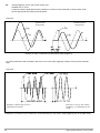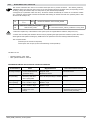
1
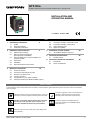
GTF-Xtra
POWER CONTROLLER WITH OVERCURRENT FAULT PROTECTION
INSTALLATION AND
OPERATION MANUAL
code 80994 - 10-2013 - ENG
INDEX
1 Preliminary instructions
1.1 Profile
1.2 General description
2
3.7 3.8
3.9
3.10
2 Installation and Connection
2.1 Electrical power supply
2.2 Notes on electrical safety and
4
4
Installation of serial network
1.3
2.3
2.4
2.5
2.6
3
Preliminary instructions 4.1“AUTOBAUD SERIAL” sequence
electromagnetic compatibility
Recommendations for correct installation for
purposes of EMC
Dimensions
Installation
General description GTF 25-60A
Electrical connections
3.1
3.2
3.3
3.4 3.5 3.6 Connection example: comunication ports
Connection example: power section
Option electronic fuse
Digital input (PWM)
23
5 Technical Characteristics
5.1 Derating Curves
25
6 Technical-Commercial information
6.1Accessories
6.2 Fuses / Fuseholders
28
10
Power connections
Connections input/output 25-120A
Functions of indicator leds
Control connectors
Configuration TTL port (GTF standars)
Serial comunication port Modbus RS485 (option)
GRAPHIC SYMBOLS
To differentiate the type and importance of the information in this User Manual, graphic reference symbols are used to make such information
easier to interpret.
Indicates contents of sections, general instructions, notes, and
other points to which the reader’s attention needs to be called.
Indicates a suggestion based on the experience of
GEFRAN’s Technical Personnel that could be
especially useful under certain circumstances.
Indicates a particularly delicate situation that could affect
the safety or correct operation of the controller, or an
instruction that MUST be followed to prevent hazards.
Indicates a reference to Detailed Technical
Documents available on the GEFRAN website
www.gefran.com.
Indicates a risk to the user’s safety due to high voltage at the
points indicated.
80994_MHW_GTF-Xtra_10-2013_ENG
1
1 • PRELIMINARY INSTUCTIONS
1.1
Profile
Device parameters can be configured from PC, by means of a sim-
ple configuration SW which lets you save all parameters in a con-
The Gefran GTF-Xtra power controller combines the functiona-
figuration file that is easy to manage and to copy to other devices.
controller with the benefits of the unique integrated overcurrent
Modbus RTU protocol to control currents, voltages, powers, load
The fault protection eliminates the need for extra-rapid fuses,
PLC.
lity of a single, two or three phase solid-state power unit and
Moreover, an RS485 serial connection of GTF is offered with
fault protection function.
status, and device status from the supervisor terminal (HMI) or
reducing machine downtime and the cost of replacing fuse fai-
The section contains general information and
warnings to be read before installing, configuring and
using the controller.
lures. It does so by instantaneously monitoring load current,
cutting the power if the load reaches a pre-set threshold and
isolating the power switching devices.
In applications susceptible to intermittent short-circuits and
overloads, the Gefran Xtra power controller can be programmed to restore power automatically when the fault has cleared,
preventing complete process shutdown and maintaining production.
Alternatively, power can be manually restored, locally or remotely.
A soft-start ramp is applied when the current is restored, to prevent system damage in the event that the fault is not effectively
cleared.
The GTF-Xtra controller is compact, modular and optimised to
control virtually any type of restive heating system in a wide
range of industrial applications.
Impressive functionality is assured by a comprehensive array of
1.2
General Description
GTF is single-zone advanced solid state power unit, extremely
compact, equipped with different optional functions; it offers an
exclusive combination of performance, reliability, and flexibility.
In particular, this new line of Gefran controllers is the ideal
solution for sectors demanding high performance and continuity
of service, such as:
• Metal heat treating furnaces
• Vacuum furnaces with graphite elements
• High-temperature furnaces
• Boosters for glass lines
options that are configurable with intuitive, guided-set-up, PCbased Windowstm software.
• Quick cutting on blow molding lines
Modbus RTU protocol to control currents, voltages, powers,
The modules series GTF controllers are based on an extremely
(HMI) or PLC
the best I/O configuration for your system.
GTF runs complete diagnostics of current, voltage, power, and
loads, including resistive loads with high and low temperature
• Machines and lines with unwanted current peaks and arcs
GTF-Xtra always provides an RS485 serial connection with
• “Fuse-free” solutions
load status, and device status from the supervisor terminal
versatile hardware and software platform, with options to select
temperature levels:
Current Diagnostics:
- Total and partial load interrupt alarm
- Self-learn function of alarm limit for interrupted load
- Alarm for SSR in short circuit
GTF is used for the power control of single-phase and 2-phase
coefficient, short wave IR lamps, or transformer primaries.
Attention: the description of programming and
co n fi g u r a ti o n p a ra me te rs a re co n ta i n e d i n
the “Programming and configuration” manual,
downloadable from the website www.gefran.com
- Alarm for load in short circuit or overcurrent
Voltage Diagnostics:
- Alarm for absence of phase
Temperature Diagnostics:
- Alarm for over temperature of power module
Power control with Soft start ramp limits load, optimizes the consumptions and increases the load operating duration.
This exclusive function is a resettable internal protection against
overcurrents: it eliminates the external (always problematic) use
of high-speed fuses and greatly reduces the length and cost of
machine downtime caused by a search for new fuses.
2
80994_MHW_GTF-Xtra_10-2013_ENG
1.3
Preliminary instruction
See paragraph 2.1 “ Dimensions and mounting” before installing
Read the following preliminary instructions before
installing and using the GTF modular power
controller.
This will make start-up faster and avoid some
problems that could be mistakenly interpreted as
To configure the PC use the SW Gefran GF-Express kit and the
malfunctions or limitations of the controller.
Immediately after unpacking the unit, check the order code
and the other data on the label attached to the outside of the
container.
Write them on the following table.
This data must always be available and given to Gefran
SN............................... (Serial number)
CODE......................... (Product code)
TYPE........................... (Order code)
SUPPLY...................... (Power Supply)
VERS. ......................... (Firmware version)
the GTF on the machine/host system control panel.
relative connection cable.
For the order code, see Section:
“Technical-Commercial Information”.
Users and/or system integrators who want detailed
information on serial communication between
Gefran standard and/or industrial PCs and Gefran
Programmable Instruments can access Technical
Reference Documents on serial communication
and MODBus protocol, etc., in Adobe Acrobat
format on the Gefran website www.gefran.com:
• Serial Communication
• MODBus Protocol
Before calling Gefran Customer Care in case of assumed
malfunctions, please see the Troubleshooting Guide in the
“Maintenance” section and, if necessary, the F.A.Q. (Frequently
Asked Questions) section on the Gefran website
www.gefran.com
Customer Care representatives are available if technical service
is needed. Check that the controller is in perfect condition,
was not damaged during shipment, and that the package also
contains the “Configuration and Programming” manual.
Immediately report any errors, shortages, or signs of damage to
your Gefran dealer.
Check that the order code matches the configuration requested
for the intended application by consulting the section:
“Technical-Commercial Information.”
Example: Model
GTF 60 - 480 - 0 - 1 - 0 - M
Nominal current
Nominal voltage
Control option, Absent
Diagnostic option: HB
Fuse: absent
Serial Modbus
80994_MHW_GTF-Xtra_10-2013_ENG
3
2 • INSTALLATION AND CONNECTION
This section contains the instructions needed for
correct installation of GTF controllers on the
machine/host system control panel and for correct
connection of the power supply, inputs, outputs and
interfaces.
CAREFULLY READ THE FOLLOWING WARNINGS
BEFORE INSTALLING THE INSTRUMENT!
Disregard of such warnings could create
electrical safety and electromagnetic
compatibility problems, as well as void the
warranty.
2.1
Electrical power supply
• the controller DOES NOT have an On/Off switch: the user
must install switch/isolator conforming to safety requisites (CE mark) to cut off the power supply up-line of the controller.
The switch must be installed in the immediate vicinity of the
controller in easy reach of the operator.
A single switch can be used for multiple devices.
2.3
Recommendations for Correct Installation
for purposes of EMC
2.3.1
Instrument power supply
• The power supply for the electronic instrumentation on the
panels must always come directly from a cut-off device with
fuse for the instrument part.
• Electronic instrumentation and electromechanical power
devices such as relays, contactors, solenoids, etc., MUST
ALWAYS be powered by separate lines.
• When the power supply line of electronic instruments is
heavily disturbed by switching of thyristor power groups or
by motors, you should use an isolation transformer only for
the controllers, grounding its sheathing.
• It is important for the system to be well-grounded:
- voltage between neutral and ground must not be > 1V
- Ohmic resistance must be < 6Ω;
• If the grid voltage is highly unstable, use a voltage stabilizer.
• In proximity of high-frequency generators or arc welders,
use adequate grid filters.
• The power supply lines must be separate from instrument
input and output lines.
•Supply from Class II or from limited energy source
* the earth connection must be made with a specific lead.
• if the product is used in applications with risk of harm to
persons or damage to machines or materials, it MUST be
equipped with auxiliary alarm devices.
It is advisable to provide the ability to check for tripped alarms
during regular operation.
DO NOT install the product in rooms with hazardous
(inflammable or explosive) atmosphere; it may be connected
to elements that operated in such atmosphere only by means
of appropriate interfaces that conform to current safety
standards.
2.2
Notes on electrical safety and
electromagnetic compatibility:
2.2.1 CE MARKING: EMC
(electromagnetic compatibility) conformity
in compliance with Directive 2004/108/CE and following
modifications.
Series GTF controllers are mainly intended for industrial
use, installed on panels or control panels of production
process machines or systems.
For purposes of electromagnetic compatibility, the most
restrictive generic standards have been adopted, as shown
on the table.
2.2.2
LV (low voltage) conformity
in compliance with Directive 2006/95/CE.
EMC compliance has been verified with respect to
the information in Tables 1 and 2.
4
2.3.2
Input and output connections
Before connecting or disconnecting any connection, always check
that the power and control cables are isolated from voltage
Appropriate devices must be provided: fuses or automatic
switches to protect power lines.
The fuses present in the module function solely as a protection
for the GTF semiconductors.
• Connected outside circuits must be doubly isolated.
• To connect analog inputs, strain gauges, linears, (TC, RTD),
you have to:
- physically separate the input cables from those of the
power supply, outputs, and power connections.
- use braided and shielded cables, with sheathing grounded
at a single point.
2.3.3
Installation notes
Install the voltage stabilizer enclosed with the product
(see Installation section).
- Moreover, the applications with solid-state units require a safety automatic switch to section the load power line.
To ensure maximum reliability, the device must be correctly
installed in the panel in such a way as to obtain adequate heat
exchange between the heat sink and the surrounding air under
conditions of natural convection..
Fit the device vertically (maximum angle 10° to the vertical
axis) see figure 3
• Vertical distance between a device and the panel wall
>100mm
• Horizontal distance between a device and the panel wall at
last 10mm
• Vertical distance between a device and the next one at last
300mm.
• Horizontal distance between a device and the next one at last
10mm.
80994_MHW_GTF-Xtra_10-2013_ENG
Check that the cable holder runners do not reduce these distances, in this case fit the cantilever units opposite the panel
so that the air can flow vertically on the dissipator without any
obstacles.
• dissipation of device thermic power with effects on installation
room temperature.
• thermal power dissipation with limits on installation room temperature.
• requires exchange with external air or an air conditioner to transfer dissipated power outside the panel.
• maximum limits of voltage and derived power of transients on
the line, for which the solid state power unit contains protective
devices (based on the model).
• presence of dispersion current in GTF in non-conducting state
(current of a few mA due to RC Snubber circuit to protect ).
GEFRAN S.p.A. assumes no liability for any damage to persons or property deriving from tampering, from incorrect or improper use, or from
any use not conforming to the characteristics of
the controller and to the instructions in this User
Manual.
Table 1 EMC Emission
AC semiconductor motor controllers and conductors for non-motor EN 60947-4-3
loads
Emission enclosure
EN 60947-4-3
compliant in firing mode single cycle and phase angle if external CISPR-11
filter fitted
EN 55011
Class A Group 2
Table 2 EMC Immunity
Generic standards, immunity standard for industrial environments
EN 60947-4-3
ESD immunity
EN 61000-4-2
4 kV contact discharge
8 kV air discharge
RF interference immunity
EN 61000-4-3 /A1
10 V/m amplitude modulated
80 MHz-1 GHz
10 V/m amplitude modulated
1.4 GHz-2 GHz
Conducted disturbance immunity
EN 61000-4-6
10 V/m amplitude modulated
0.15 MHz-80 MHz
Burst immunity
EN 61000-4-4
2 kV power line
2 kV I/O signal line
Surge immunity
EN 61000-4-4/5
Power line-line 1 kV
Power line-earth 2 kV
Signal line-earth 2 kV
Signal line-line 1 kV
Magnetic fields immunity
Test are not required.
Immunity is demonstrated by
the successful completion of
the operating capability test
Voltage dips, short interruptions and voltage immunity tests
EN 61000-4-11
100%U, 70%U, 40%U,
Table 3 LVD Safety
Safety requirements for electrical equipment for measurement,
control and laboratory use
EN 61010-1
UL 508
ATTENTION
This product has been designed for class A equipment. Use of the product in domestic environments may cause radio
interference, in which case the user may be required to employ additional mitigation methods.
EMC filters are required in PA mode (Phase Angle, i.e., SSR trigger with phase angle modulation).
The filter model and current level depend on the configuration and load used.
The power filter MUST by connected as close as possible to the GTF.
You can use a filter connected between the power line and GTF or an LC group connected between the GTF output and the load.
The CE declaration of conformity is available on request
80994_MHW_GTF-Xtra_10-2013_ENG
5
6
RAM
INPUT TA
7.5V
EEprom
DIGITAL INPUT
1KV
Main Processor
MAIN INPUT IN1
18...32Vdc
1KV
POWER SUPPLY
CPU
INPUTS
5V
DC / DC
1KV
OUT HB
MODBus RS485
LEDs
LOGIC
OUTPUTS
1KV
SSR
max 480Vac
POWER CONTROL
4KV
Connected to
90...480V
Connected to
5V (PORT 1)
Connected to
18...32Vdc
Connected to 7.5V
CPU
Legend
INSULATION DIAGRAM
80994_MHW_GTF-Xtra_10-2013_ENG
2.4
Dimensions
Fastening may be done on DIN guide (EN50022) or with (5MA). See figures 1 and 2.
All dimensions are expressed in mm.
Figure 1
GTF 25 (without fan)
GTF 40 (with fan)
GTF 50 (with fan)
GTF 60 (with fan)
Fan
Depht 143 mm
Depht 143 mm
Overvoltage
protector
Fastening may be done on DIN guide (EN50022) or with (5MA).
All dimensions are expressed in mm.
2.4.1
Template dimensions
W
Figure 2
M5
L (mm)
W(mm)
GTF 25-40-50A:
112
44
GTF 60A:
112
113
Models
80994_MHW_GTF-Xtra_10-2013_ENG
L
7
2.5
Installation
Attention: respect the minimum distances shown in figure 3 to provide adequate air circulation.
Figure 3
For correct attachment/release of the module on the DIN guide, do as follows:
- keep the attach/release cursor pressed
- insert/remove the module
- release the cursor
Figure 4
Figure 5
GTF
locked properly
to DIN bar
PHASE attachment
PHASE release
1
1
PRESS
PRESS
2
TURN
8
Figure 6
2
TURN
80994_MHW_GTF-Xtra_10-2013_ENG
2.6 General description GTF 25-60A
Figure 7
GTF Standard
80994_MHW_GTF-Xtra_10-2013_ENG
GTF with RS485 option
1. Supply/control connnector
2. HB key calibration
3. TTL port for configura-
tion
4. LED indicators
5. Power terminal “Line” (1/L1)
6. Power terminal “Load” (2/T1)
7. Heatsink
8. Attachment DIN bar
9. Switch serial line terminal
10.RS485 serial port connector
11.Address Rotary switch
12.GTF Surge protector
9
3 • ELECTRICAL CONNECTIONS
3.1 Power connections
RECOMMENDED WIRE GAUGES
Table 4
GTF CURRENT LEVEL
TERMINAL
25A
1/L1, 2/T1, PE
40A
1/L1, 2/T1, PE
50A
1/L1, 2/T1, PE
60A
1/L1, 2/T1, PE
-
3/L2 (Ref. Vline)
10
CABLE WIRE
wire terminal
tightening torque /
TOOL
4 mm²
Wire terminal / Eye
D. 6mm
2 ...2.5 Nm / Phillips screwdriver
PH2 - PH3
10 mm²
Wire terminal / Eye
D. 6mm
2 ...2.5 Nm / Phillips screwdriver
PH2 - PH3
10 mm²
Wire terminal / Eye
D. 6mm
2 ...2.5 Nm / Phillips screwdriver
PH2 - PH3
16 mm²
Wire terminal / Eye
D. 6mm
2 ...2.5 Nm / Phillips screwdriver
PH2 - PH3
wire terminal tip
0.5 ...0.6 Nm / Screwdriver blade
0.6 x 3.5 mm
10 AWG
7 AWG
7 AWG
5 AWG
0.25 ...2.5 mm²
23...14 AWG
80994_MHW_GTF-Xtra_10-2013_ENG
3.2 Connections Input/Output gtf 25-120a
Figure 8
Top view
WITH option Fieldbus
Top view
WithOUT option Fieldbus
Key HB
Key HB
J2
TTL port for
PC configuration
Address x 1
J3, J4
RJ10 connectors
RS485 serial line
Modbus
Address x 10
Switch for serial line
(GND)
Syncronous output for
Master/Slave connection
Input control signal (+)
Potentiometer output power supply (+5Vdc)
Digital input (PWM input)
Alarm output
(solid state relay - HB option)
Power supply terminal 24Vac/Vdc
J1
Power supply /control
connector
Key HB
Fixing screw
at heatsink
Green Led (RUN)
Yellow Led (STATUS)
Identification label
Red Led (Alarm output HB)
Yellow Led (Status digital input)
Fixing screw
at heatsink
Led: Green = Thyristor ON
Yellow = Temperature OVER
2/T1
Load connection
1/L1
LINE connection
3/L2
Reference connection
of line voltage
PE
EARTH
80994_MHW_GTF-Xtra_10-2013_ENG
11
3.4Functions of indicator leds
Description of LEDs
Table 5
LED
DESCRIPTION
COLOR
Flashing during normal operation
RUN
green
On steadily: according to FW setting (see SW manual)
Off : during normal operation
STATUS
yellow
On : according to FW setting (see SW manual)
ALARM
State HB alarm output / Power Fault Alarm / Fuse Open
red
DI
State digital input
yellow
.Green: SSR on control state
green
Yellow: ON SSR overtemperature alarm
yellow
ON / OVER-TEMP
The state of the LEDs matches the corresponding parameter, except in the following special cases:
- LED 1 (green) + LED 2 (yellow) both flashing rapidly: autobaud in progress
- LED 2 (yellow) flashing rapidly: SSR temperature sensor broken or SSR Over Heat or Rotation Error
or Load_short_protection
3.5
Control connector
3.5.1Connector J1
Figure 9
Table 6
Figure
10
0,2 - 2,5mm2
24-14AWG
0,25 - 2,5mm2
23-14AWG
Connection schema J1
Table 7
PIN
Name
Decription
OUT AL HB
OUT Alarm Switch (HB)
3
OUT_Master
Control output Slave (+7V)
4
GND
GND Control analog input
5
+ IN
+ Control analog input
1
2
12
6
+5V_POT
Output alim. potentiometer
7
IN_DIG
Digital input & PWM Input
8
24V Supply
9
24V Supply
Supply 18...32 Vac/Vdc
80994_MHW_GTF-Xtra_10-2013_ENG
3.6Configuration TTL port (GTF Standard)
Connector J2 GTF
Connector S1/S2
RJ10 4-4 pin
Nr. Pin
Nome
Description
1
GND
Ground
2
Rx_TTL
Data reception TTL from GTF
3
TX_TTL
Data transmission TTL to GTF
4
(Reserved Gefran)
DO NOT connect
4
3
2
Note
The use of this port is recommended
to configure parameters by Accessory
Gefran cable code F049095 (USB /
TTL)or Gefran cable code F043956
(RS232 / TTL) ONLY
1
Cable type: flat telephone cable for pin 4-4 conductor 28AWG
3.7Serial communication ports modbus rs485 (Option)
Connectors J3, J4 GTF
Connector S1/S2
RJ10 4-4 pin
4
3
2
Nr. Pin
Name
Description
Note
1
GND1 (**)
2
Tx/Rx+
Data reception/transmission (A+)
3
Tx/Rx+
Data reception/transmission (B-)
4
+V (reserved)
(*) Insert the RS485 line termination
in the last device on the Modbus line,
see dip-switches.
(**) Connect the GND signal between
Modbus devices with a line distance
> 100 m.
1
Cable type: flat telephone cable for pin 4-4 conductor 28AWG
3.8Connection example: communication ports
Integration of GTF with GEFLEX modules connected in RS485 Modbus
Figure 11
Flat
RS485
80994_MHW_GTF-Xtra_10-2013_ENG
13
3.9Connection example: Power section
Connection example GTF for 1 single-phase load, single-phase line (L1-N) or open delta (L1-L2)
Figure 12
Connection example GTF for 1 single-phase load with transformer single-phase line (L1-N) or open delta (L1-L2) .
Figure 13
14
80994_MHW_GTF-Xtra_10-2013_ENG
Connection example 2-phase (Master-Slave) GTF for one load 3-phase
Figure 14
Connection example 3-phase (Master-Slave with control on 3 lines) GTF for one load 3-phase
Figure 15
80994_MHW_GTF-Xtra_10-2013_ENG
15
Connection example GTF three-phase (3 master units) for single-phase loads, with division of maximum load with
isolators S1, S2, S3, maintaining balance of three-phase line.
Figure 16
Connection example GTF (with N. 3 GTF) for 3-phase star load with neutral
Figure 17
16
80994_MHW_GTF-Xtra_10-2013_ENG
NOTES: USE WITH INDUCTIVE LOADS AND TRANSFORMERS
a) b) c) d) e) f) g)
Connect a varistor (MOV) between each wire of the primary transformer and ground.
Varistor data: rated voltage 660Vrms,…, 1000Vrms; minimum energy 100J
The maximum current controllable by the device is less than the product’s rated value (see technical data).
In ZC and BF trigger mode, use the Delay-triggering function to limit peak magnetization current.
In PA trigger mode, use the Softstart function.
DO NOT use HSC trigger mode.
DO NOT connect RC snubbers in parallel to the transformer primary.
Select the inductive load using the Hd.1 parameter (ref. Software manual)
Trigger modes
The GTF has the following power control modes:
- modulation via variation of number of conduction cycles with zero crossing trigger.
- modulation via variation of phase angle.
Zero Crossing mode
This function eliminates EMC noise. This mode controls power on the load via a series of conduction ON and non
conduction OFF cycles.
ZC - constant cycle time (Tc ≥ 1 sec, settable from 1 to 200 sec)
Cycle time is divided into a series of conduction and non conduction cycles in proportion to the power value to
be transferred to the load.
Figure 18
For example, if Tc = 10sec, if the power value is 20% there is conduction for 2 sec (100 conduction cycles @ 50Hz)
and non conduction for 8 sec (400 non conduction cycles @ 50Hz).
BF - variable cycle time (GTT)
This mode controls power on the load via a series of conduction ON and non conduction OFF cycles.
The ratio of the number of ON cycles to OFF cycles is proportional to the power value to be supplied to the
load.
The CT repeat period is kept to a minimum for each power value (whereas in ZC mode the period is always
fixed and not optimized).
80994_MHW_GTF-Xtra_10-2013_ENG
17
Figure 19
parameter defines the minimum number of conduction cycles settable from 1 to 10.
In the following example, the parameter = 2.
HSC - Half single cycle
This mode corresponds to Burst Firing that manages ON and OFF half-cycles. It is useful for reducing the
flickering of filaments with short/medium-wave IR lamp loads. With these loads, to limit operating current with
low power, it is useful to set a minimum power limit (for example, Lo.p = 10%).
NB:This mode is NOT allowed with inductive loads (transformers) It is used with resistive loads in single
phase, star with neutral, or open delta configuration.
Figure 20
Example of operation in HSC mode with power at 33 and 66%.
Phase angle (PA)
This mode controls power on the load via modulation of trigger angle q
Example: if power to be transferred to the load is 100%, q = 180°
or
if power to be transferred to the load is 50%, q = 90°
Figure 21
Resistive load
18
Inductive load
80994_MHW_GTF-Xtra_10-2013_ENG
ADDITIONAL FUNCTIONS
Softstart
This type of start can be enabled either in phase control or pulse train mode and in zero-crossing mode (ZC, BF,
HSC).
In phase control, the increment of conduction angle q stops at the corresponding value of the power to be transferred
to the load.
Control of maximum peak current (useful in case of short circuit on the load or of loads with high temperature
coefficients to automatically adjust start time to the load) can be enabled during softstart. When the load shut-off time
(settable) is exceeded, the ramp is reactivated at the next power-on.
Figure 22
Example of firing ramp with phase Soft-Start
RMS current limit
The option for controlling the load current limit is available in all work modes.
If the current value exceeds the limit (settable in the nominal full-scale range) in mode PA the conduction
angle is limited, while in zero-crossing mode (ZC, BF, HSC) the cycle time conduction percentage is limited.
This limitation ensures that the RMS value (i.e., not the instantaneous value) of the load current does NOT
exceed the set RMS current limit.
Figure 23
Example of conduction angle limitation in PA mode to respect an RMS current limit below the nominal current of the
load.
80994_MHW_GTF-Xtra_10-2013_ENG
19
DT - “Delay triggering” (for ZC, BF control modes only)
Settable from 0° to 90°.
Useful for inductive loads (transformer primaries) to prevent current peak that in certain cases could
trip the high-speed fuses that protect the SCRs.
Figure 24
Transient with
Over-Current
Transient without
Over-Current
Example of firing of inductive load with/without delay-triggering.
To conduct inductive loads controlled in PA mode, do not use delay triggering; instead, use the phase Soft-Start
ramp.
Figure 25
Example of phase ramp to fire a
transformer in PA mode
Example of firing with DelayTriggering of a transformer in ZC
mode
Comparison of method to fire a transformer: Soft-Start Ramp (for PA mode) / Delay triggering (for ZC and BF mode)
20
80994_MHW_GTF-Xtra_10-2013_ENG
3.10Overcurrent fault protection
This function eliminates the need for an external extra-rapid fuse to protect the device. The SHORT_CIRCUIT_
CURRENT alarm trips when the peak current on the load exceeds maximum permitted value (corresponding to twice
the rating ) during the softstart ramp or at first power-on (with softstart ramp disabled).
If configured (Fr.n parameter other than zero), the device restarts automatically in softstart for a maximum number
Fr.n of attempts, beyond which it remains deactivated while waiting for manual reset with front panel key BUT or with
the control via serial (bit 16).
83
R/W
Fr.n
16
bit
Number of restarts in case of FUSE_OPEN
Reset alarms SHORT_CIRCUIT_CURRENT E FUSE_OPEN
R/W
OFF= ON = Reset alarms SHORT_CIRCUIT_CURRENT e FUSE_OPEN
- DOES NOT replace any of the safeties on the system (such as magnetothermic switches, delay fuses, etc.).
- Protects the controller (and therefore also the load) by replacing the high-speed fuse needed to protect the control
SCRs against faults (without creating any additional cost to replace the fuse and reducing machine downtime).
-Has 2 function states:
√ Normal (On-Off control of load power)
√ Fuse-Open: GTF is open (a short occurred during normal operation).
Conditions of use
-
-
Breaking capacity: 5 KA - 480V
Max. system inductance: 1000 uH
Differences among SHORT CIRCUIT protection devices
Characteristics
Fuses
Magnetothermics
Overcurrent Fault Protection
Opening technique
• Metal melting
• Contact withdrawal with
preloaded spring
• Thermal effect
• Magnetic effect
• Mechanical release
Arc quenching
• Arc in air / sand
• Quenching with silica
sand / spring effect
• Mechanical separation of 2 contacts • No arc in air (current shuts down
• Arc in air with quenching in chamber in silica)
Opening energy
(I²t of opening)
Depending on model:
• Low – medium – high
Depending on model:
• Medium – high
• Always very low
Opening time
Depending on model:
• Low – medium – high
Depending on model:
• Medium – high
• Always very low (micro-seconds)
Reset
• Replacement
• Labour cost + fuse
change
• Manual reset
• Manual reset
• Automatic reset (“FR.n” times)
• Remote reset (via serial)
80994_MHW_GTF-Xtra_10-2013_ENG
• Current threshold
• Device shutdown
21
3.11
Digital input (PWM)
This digital input can be used to receive information on the % of power to be supplied to the load.
The signal can be generated by a controller or external plc via digital outputs (logic output for Gefran instrumentation).
This is obtained by alternating the output in ON for time TON with the output in OFF for time TOFF.
The sum of TON+TOFF is constant, and is called CycleTime.
CycleTime= TON+TOFF
The power level is given by the ratio = TON/ CycleTime and is normally expressed in %.
The GTF digital input automatically adapts to the cycle time from 0.03Hz to 100Hz and obtains the power % to be supplied to the load from the TON/(TON+TOFF) ratio.
Connection example:
Temperature control with Gefran 600 with D type logic output (out2) (cycle time: 0.1sec), logic output can drive max 3 GTF in series (preferable), connection allowed only if GTFs do not have interconnected GNDs (if so, make parallel connection).
To use Digital PWM the GTF can be ordered with the configuration 5 -x - M or must be configured with the parameter dIG (digital input) = 7 (see Fig. 46, 47).
Figure 26
22
80994_MHW_GTF-Xtra_10-2013_ENG
4 • INSTALLATION OF THE SERIAL PORT
A network typically has a Master that “manages” communication by means of “commands,” and Slaves that carry out these
commands.
GTF modules are considered Slaves to the network master, which is usually a supervision terminal or a PLC.
It is positively identified by means of a node address (ID) set on rotary switches (tens + units).
A maximum of 99 GTF, modules can be installed in a serial network, with node address selectable from “01” to “99”
GTF modules have a ModBus serial (Optional)
The MODBUS RTU port 1 has the following factory settings (default):
Parameter
Default
Range
ID
1
1...99
BaudRate
19,2Kbit/s
1200...19200bit/s
Parity
None
Odd/Even/None
StopBits
1
-
DataBits
8
-
The following procedures are indispensable for the Modbus protocol.
Set the rotary switch at “0+0” for AutoBaud function
Parameter
AutoBaud
PLC / HMI
Position
rotary switches
tens unit
0
0
Allows setting of the
correct BaudRate value
automatically detecting
the master transmission
frequency
RS485 MODBUS RJ10 Cable
GTF with RS485
NOTE
The standard products DO NOT feature the comunication RS485 Modbus serial port, but can be configured via PC with Gefran
GF-Express Software, by connecting it to TTL port of GTF to PC, by means of TTL cable equipped with SW.
PC
RS232 or
USB
Gefran Adapter
F049095
F043956 or
TTL cable RJ10
GTF standard
NEVER connect TTL adaptator to RS485 serial port of GTF.
NEVER connect TTL connector or GTF to a RS485 serial web .
Danger of product damage!!
80994_MHW_GTF-Xtra_10-2013_ENG
23
4.1 “AUTOBAUD SERIAL 1” sequence
Function
Adapt the serial communication speed and parity of the GTF
modules to the connected supervision terminal or PLC.
The “RUN”and “STATUS” LEDs mentioned in the
procedure can vary its behavior based on on he
parameters Ld.1 e Ld.2
Procedure
1) Connect the serial cables for all modules on the network t
and to the supervision terminal.
2) Set the rotary switch on the GTF modules to be installed,
or on all modules present in case of first installation, to
position “0+0”.
3) Check that the “RUN” and “STATUS” LEDs flash at high
frequency (10Hz).
4) The supervision terminal must transmit a series of generic
“MODBUS” read messages to the network.
5) The procedure is over when all of the “RUN” and
“STATUS”LEDs on the GTF modules flash at a normal
frequency (2Hz) (if parameter 50 Ld.1 = 16 as default).
The new speed parameter is saved permanently in each GTF;
therefore, the “AUTOBAUD SERIAL” sequence does not have
to be run at subsequent power-ups.
When the rotary switch is turned, the green
“STATUS” LED stays on steadily for about 6
seconds, after which it resumes normal operation and
saves the address.
24
INSTALLATION OF
SERIAL NETWORK 1
ModBus
YES
?
The serial network communication
speed is the same as for
GTF.
NO
“AUTOBAUD”
SERIAL 1
SEQUENCE
“RUN and STATUS”
LEDs flashes at 10 Hz
SETTING
THE NODE
ADDRESS
OPERATIVE
FUNCTION
80994_MHW_GTF-Xtra_10-2013_ENG
5 • TECHNICAL CHARACTERISTICS
Inputs
IN1 Analogic control inputs
Function
Acquisition of control power
Max. error
1% f.s.+/- 1 scale point at ambient temperature of 25°C
Thermal drift
< 100 ppm/°C of f.s.
Sampling time
60 ms
Scale 0 -10V
Input impedance > 40 Kohms
Scale 0-5V
Input impedance > 40 Kohms
Scale 0-20mA or 4-20mA
Internal Shunt resistance: 125 ohm
Potentiometer input
Potentiometer resistance: from 1 Kohm to 47 Kohm
Potentiometer supply: +5V (supplied by GTF, max 10mA)
Linear input read scale
0 .... 100.0 %
INDIG Digital Input
Function
Power Disable input or PWM input
Voltage range
5-30V (max 7 mA)
State “0” read safe voltage
<2V
State “1” read safe voltage
> 5V
PWM input
Maximum frequency: (0.03Hz,...,100 Hz) maximum resolution 1% (0.1ms)
Measures voltage and line current
Function measures the load current
Measures RMS voltage by integral calculation of sampled values
Meas. range: 0 ... 2 * rated_product
Accuracy RMS current measurement
3 % f.s. at room temperature of 25°C
In PA mode with conduction angle >90° : 5% fs
Thermal drift: < 200 ppm/°C
RMS line current measurement function
RMS voltage meas. by integral calculation of sampled values
Work voltage range: 90...480Vac)
Accuracy RMS voltage measurement
1 % f.s. at room temperature of 25°C
Thermal drift: < 100 ppm/°C
Sampling time current/voltage
0,25 ms
Line frequency
50 / 60 Hz
CONTROL OUTPUT MASTER/SLAVE
Function
OUtputs
Control for synchronising another GTF or GTS slave (4 slave max.)
Voltage: 7.5V , max 25 mA
HB ALARM OUTPUT
Function
HB alarm output or of other configurable alarms
Type
Solid state relay (MOS opto)
Isolated contact, normally open
Imax: 150mA Vmax. 30 Vac / Vdc
Closing resistance < 15 ohm
RS485 Modbus (Optional)
COMMUNICATIONS PORTS
Function
Local serial communication
Protocol
ModBus RTU
Baudrate
Settable 1200 …19200 bit/s (default 19,2Kbit/s)
Node address
Settable with two rotary-switches (rotary-switches)
Type
RS485 - double connector RJ10 telephone type 4-4
Isolation
500V
TTL serial connector (Standard)
Function
For product initial configuration only, via PC.
Use a PC connected to GTF, ONLY via Gefran adapter
Code F049095 (PC with USB) or Code F043957 (PC with RS232)
Isolation
TTL serial NOT isolated of CPU
80994_MHW_GTF-Xtra_10-2013_ENG
25
POWER (Solid-state)
CATEGORY OF USE
(Tab. 2 EN60947-4-3)
AC 51 resistive or low inductance loads
AC 55b short wave infrared lamp (SWIR)
AC 56a: transformers, (Request application check)
Trigger mode
PA - Load management by adjusting the firing angle (only configuration single-phase
or delta open)
ZC - Zero Crossing with constant cycle time (settable in range 1-200sec)
BF - Burst Firing with variable cycle time (GTT) optimized minimum.
HSC - Half Single Cycle corresponds to Burst Firing that includes ON and
OFF half-cycles.
Useful for reducing flicker with short-wave IR loads (applied only to
single-phase resistive or 3-phase 6-wire open delta loads).
Feedback mode
V, V2: Voltage feedback proportional to RMS voltage value on load
(useful to compensate possible variations in line voltage).
I, I2: Current feedback: bound to RMS current value on load to
compensate variations in line voltage and/or variations in load impedance.
P:
Power feedback: proportional to real power value on load (useful to keep
constant values of electrical power assigned regardless of load impedance
or line voltage variations).
Max rated voltage
480Vac
Work voltage range
90…530Vac
Non-repetitive voltage
1200Vp
Rated frequency
50/60Hz auto-determination
MODEL GTF
Rated current AC51 -AC55b non-inductive or slightly
inductive loads, IR lamps (@ Tamb = 40°C)
25
Rated current AC56A permitted trigger modes: ZC, BF
con DT (Delay Triggering),PA with softstart (@ Tamb
=40 °C)
40
50
60
25A
40A
50A
60A
20A
32A
40A
50A
Overcurrent Fault Protection function
This option eliminates the need for an external extra-rapid fuse to protect the device.
In case of load short-circuit, the internal IGBT device is instantaneously switched off
and the alarm status is signaled.
Critical Dv/dt with output deactivated
1000V/μsec
Held nominal voltage of on the impulse
4KV
Breaking
5KA/480V
FUNCTION
Diagnostics
Detection of short load circuit
absence line voltage, HB alarm (partial breakage of load)
OPTIONS
Options
- Timed Soft-Start firing ramp, with or without peak current control
- Soft-Start firing ramp, specific for infrared lamps
- Timed shut-off ramp
- Limitation of RMS current in load
- 0-90° Delay-Triggering for firing inductive loads in ZC and BF mode
Diagnostic
- SSR in short circuit (presence of current with OFF control)
- Absence of SSR current when under load.
- Overtemperature alarm
Current read
• HB alarm interrupted or partially interrupted load
• Automatic calibration of HB alarm setpoint starting from current value in load
• Alarm for load in short circuit or overcurrent
Voltage read
• No line voltage
GENERAL DATA
Power supply
GTF 25-60A: 24 Vac 50-60 Hz / Vdc ± 25%, max 3VA
Power supply external fan
(only for 40, 50,60A model)
24 Vdc ± 10%, max 200mA
Signals
5 leds: RUN: run state of CPU
STATUS: operating state
ALARM: state of alarm output
DIGITAL INPUT: state of digital inputs
ON / OVER-TEMP.: state control tirystor / Alarm for overheating
Load type and connection
Single phase load
Independent single-phase load in open delta
3-phase load
3-phase load (star without neutral or closed triangle) with bi-phase control
26
80994_MHW_GTF-Xtra_10-2013_ENG
GENERAL DATA
Protection
IP20
Work/storage temperature
0…40°C (refer to dissipation curves) / -20 °C - +70 °C
average temperature over a period of 12:0 am not exceeding 35° C
(according to EN 60947-4-3 § 7.1.1)
Relative humidity
20…85% RH non-condensing
Ambient conditions for use
indoor use, altitude up to 2000m
Installation
DIN bar EN50022 or panel with screws
Installation requirements
Installation category II, pollution level 2, double isolation (only for model >120A):
- Max. temperature of air surrounding device 40°C; for temperature >40°C refer at
derating curves
- Device type: “UL Open Type”
Weight
GTF 25A
0,97 Kg
GTF 40, 50A
1,1 Kg
GTF 60A
1,5 Kg
5.1
Derating Curves
Figure 27
80994_MHW_GTF-Xtra_10-2013_ENG
27
6 • TECHNICAL / COMMERCIAL INFORMATION
This section contains information on order codes for
the Controller and its main accessories.
immediately identifies the unit’s hardware configuration.
Therefore, you must always give the order code when
contacting Gefran Customer Care for the solution to any
problems.
As mentioned in the Preliminary Instructions in this
User Manual, a correct reading of the Controller order code
GTF -
1
480
2
nominal current
FIELDBUS
25A
25
0
Absent
40A
40
M
MODBUS RTU
50A
50
60A
60
CONTROL OPTIONS
Note: All models have 480VAC nominal voltage and are equipped with a partial/
total load interrupt (HB) function)
1
Signal control (configurable)
10V (Default)
1
5V/Potentiometer
2
0-20mA
3
4-20mA
4
PWM/Digital input
5
B
0
Absent
1
Current limit
2
Current limit
and feedback V, I, P
M
Note:
Configurator Standard 1-B-M, if not differently
specified .
Substitution model:
GTS
GTF - X - 480 - 0 - 0 - 0 - 0 - 5 - Z - S
GTT
without load interrupted option
Trigger modes (configurable)
GTF - X - 480 - 0 - 0 - 0 - 0 - 1 - B - M
ZC
Z
BF (Default)
B
GTT
with load interrupted option
HSC
H
GTF - X - 480 - 0 - 1 - 0 - 0 - 1 - B - M
PA
P
Function type (configurable)
28
Master (Default)
M
Slave
S
Slave dual-phase
S2
80994_MHW_GTF-Xtra_10-2013_ENG
6.1
Accessories
CONFIGURATION KIT
KIT PC USB / RS485 o TTL
kit for PC via the USB port (Windows environment) for GTF standard configuration (TTL
port) for configuration of GTF with the RS485 option
Lets you read or write all of the parameters of a single GTF
A single software for all models
• Easy and rapid configuration
• Saving and management of parameter recipes
• On-line trend and saving of historical data
Component Kit:
- Connection cable PC USB <----> GTF port TTL
- Connection cable PC USB <----> GTF RS485 port
- Serial line converter
- CD SW GF Express installation
ORDERING CODE
GF_eXK-2-0-0....................................Cod. F049095
6.2Fuse GG
The electric protection device called FUSE GG must be done in order to grant the protection against the electric
cable short cirrcuit (see EN60439-1, par. 7.5 “Short-circuit protection and short-circuit with stand strength” and 7.6
“Switching devices and components installed in assemblies”, otherwise the equivalent EN61439-1 paragraphs)
80994_MHW_GTF-Xtra_10-2013_ENG
29