1
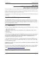
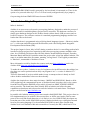
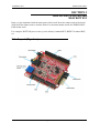
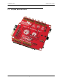
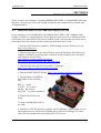
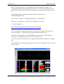
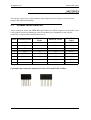
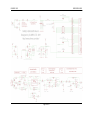
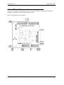
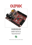
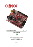
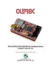
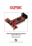
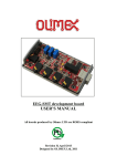
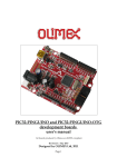
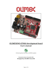
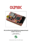
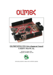
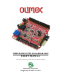
SHIELD-EKG-EMG bio-feedback shied
USER’S MANUAL
All boards produced by Olimex LTD are ROHS compliant
Initial release, Januray 2012
Designed by OLIMEX Ltd, 2011
OLIMEX© 2012
SHIELD-EKG-EMG
Disclaimer:
© 2012 Olimex Ltd. Olimex®, logo and combinations thereof, are registered trademarks of Olimex Ltd. Other
terms and product names may be trademarks of others.
The information in this document is provided in connection with Olimex products. No license, express or
implied or otherwise, to any intellectual property right is granted by this document or in connection with
the sale of Olimex products.
Neither the whole nor any part of the information contained in or the product described in this document may be
adapted or reproduced in any material from except with the prior written permission of the copyright holder.
The product described in this document is subject to continuous development and improvements. All particulars
of the product and its use contained in this document are given by OLIMEX in good faith. However all
warranties implied or expressed including but not limited to implied warranties of merchantability or fitness for
purpose are excluded.
This document is intended only to assist the reader in the use of the product. OLIMEX Ltd. shall not be liable
for any loss or damage arising from the use of any information in this document or any error or omission in such
information or any incorrect use of the product.
Thank you for purchasing the SHIELD-EKG-EMG - engineered and assembled by
Olimex LTD!
WARNING:
EKG DEVICE DISCLAIMER
IEC601 is a standard that specifies tests and requirements that medical devices must pass
before they can be used on humans. However, none of the devices built from these designs
have been tested according to these guidelines because of the costs involved. Therefore, a
device based on any of these designs may not be used for medical purposes as no medical
claims are made.
Note that CONNECTING A DEVICE VIA ELECTRODES TO HUMANS OR ANIMALS IS
POTENTIALLY HAZARDOUS AND MAY RESULT IN ELECTRIC SHOCK AND/OR
SEIZURE.
Page 2 of 18
OLIMEX© 2012
SHIELD-EKG-EMG
TABLE OF CONTENTS
SECTION 1 OVERVIEW .....……...……………………………….……4
SECTION 2 SETTING UP THE SHIELD-EKG-EMG BOARD ….........6
SECTION 3 SHIELD-EKG-EMG BOARD DESCRIPTION ...….….…..9
SECTION 4 INSTALLATION EXAMPLE ..….………….….….....…..11
SECTION 5 HARDWARE ..……………………………..…….……….13
SECTION 6 SCHEMATICS …...…………...……….....….……....……15
SECTION 7 REVISION HISTORY ………………………...……….….18
Page 3 of 18
OLIMEX© 2012
SHIELD-EKG-EMG
SECTION 1
OVERVIEW
Thank you for choosing the SHIELD-EKG-EMG prototype board from Olimex! This
document provides a User’s Guide for the Olimex SHIELD-EKG-EMG. As an overview, this
chapter gives the scope of this document and lists the board’s features. The document’s
organization is then detailed.
1.1
Scope
The SHIELD-EKG-EMG is an extension module for Olimex's ARDUINO compatible boards
– like OLIMEXINO-328, OLIMEXINO-STM32 and PIC32-PINGUINO, among others. The
shield is also compatible with ARDUINO boards including ARDUINO UNO. The board
comes with mounted connectors on it.
1.2
Features
• Stackable shield (pass-through headers) - up to 6 shields forming 6 channels; mounted
•
•
•
•
1.3
on top of each other and wired to A0-A6 analogue inputs
Calibration signal generation by D4/D9 digital output
Preciese Trimmer potentiometer for calibration (all boards are shipped completely
assembled, tested and calibrated so you should not do this unless you wat to see how
things work)
Input connector for passive or active electrodes
Works with both 3.3V and 5V Arduino boards
Similar boards
MOD-EEG-SMT - an inexpensive unit for electroencephalography (EEG) - recording of
electrical activity along the scalp: http://www.olimex.com/gadgets/eeg-smt.html
PROTO-SHIELD - If you seek a board which follows the DUINO shield dimensions
specification and offers prototype area and 2 buttons with filter capacitors and 2 LEDs. Web
page of the product: http://olimex.com/dev/proto-shield.html
SHIELD-LOL – If you are searching for a shield with 126 LED matrix (14x9) available in 4
colors and 4 different sizes of the LEDs. Web page: http://olimex.com/dev/shield-lol.html
Page 4 of 18
OLIMEX© 2012
1.4
SHIELD-EKG-EMG
Organization
Each section in this document covers a separate topic, organized as follow:
Section 1 is an overview of the board usage and features
Section 2 provides a guide for quickly setting up the board and introduces the user to
Arduino/Maple/Pinguino
Section 3 contains the general board diagram and layout
Section 4 show and example of setting up SHIELD-EKG-EMG with OLIMEXINO328
Section 5 covers the connector pinout, peripherals and jumper description
Section 6 provides the schematics
Section 7 contains the revision history
Page 5 of 18
OLIMEX© 2012
SHIELD-EKG-EMG
SECTION 2
SETTING UP THE SHIELD-EKGEMG PROTOTYPE BOARD
This section helps you set up the SHIELD-EKG-EMG development board for the first time.
Please consider first the electrostatic warning to avoid damaging the board, then discover the
hardware and software required to operate the board.
The procedure to power up the board is given, and a description of the default board behavior
is detailed.
2.1 Electrostatic Warning
The SHIELD-EKG-EMG development board is shipped in a protective anti-static package.
The board must not be exposed to high electrostatic potentials. A grounding strap or similar
protective device should be worn when handling the board. Avoid touching the component
pins or any other metallic element.
2.2 Requirements
In order to set up the SHIELD-EKG-EMG prototype board, the following items are required:
- SHIELD-EKG-EMG itself
- ARDUINO compatible board* (e.g. OLIMEXINO-328, OLIMEXINO-STM32, PIC32PINGUINO)
- Electrode cable**
*The pinout for the board strictly follows the DUINO extension specification. Best choice for
a board would be OLIMEXINO-328 or any DUINO board which utilizes the ATmega328
since we have working and tested examples for those MCUs, configuring them for
ATmega128 would require tweaking of the code.
**The cable features three electrodes – two data electrodes (1 channel) and DLR electrode
(feedback). If you use more than one SHIELD-EKG-EMG you can use cables without DLR
for every shield after the first.
IMPORTANT NOTE: The electrode cables for SHIELD-EKG-EMG and MOD-EEG-SMT
differ from each other.
In case you want to build a working SHIELD-EKG-EMG system without owning a DUNIO
board the best choice would be our board OLIMEXINO-328. This is the web page for the
board: http://www.olimex.com/dev/olimexino-328.html.
2.3 Powering up the board
Page 6 of 18
OLIMEX© 2012
SHIELD-EKG-EMG
The SHIELD-EKG-EMG board is powered by the host board it is mounted on. There is the
option to be powered either by 3.3V or 5.0V host board (configured easily by a jumper).
On powering the board PWR LED must become GREEN.
2.4 Arduino/Maple/Pinguino note
What is Arduino?
Arduino is an open-source electronics prototyping platform, designed to make the process of
using electronics in multidisciplinary projects more accessible. The hardware consists of a
simple open hardware design for the Arduino board with an Atmel AVR processor and onboard I/O support. The software consists of a standard programming language and the boot
loader that runs on the board.
Arduino hardware is programmed using a Wiring-based language (syntax + libraries), similar
to C++ with some simplifications and modifications, and a Processing-based Integrated
Development Environment (IDE).
The project began in Ivrea, Italy in 2005 aiming to make a device for controlling student-built
interaction design projects less expensively than other prototyping systems available at the
time. As of February 2010 more than 120,000 Arduino boards had been shipped. Founders
Massimo Banzi and David Cuartielles named the project after a local bar named Arduino. The
name is an Italian masculine first name, meaning "strong friend". The English pronunciation
is "Hardwin", a namesake of Arduino of Ivrea.
More information could be found at the creators web page http://arduino.cc/ and in the
Arduino Wiki http://en.wikipedia.org/wiki/Arduino
To make the story short - Arduino is easy for beginners who lack Electronics knowledge, but
also does not restrict professionals as they can program it in C++ or mix of Arduino/C++
language.
There are thousands of projects which makes it easy to startup as there is barely no field
where Arduino enthusiasts to have not been already.
Arduino has inspired two other major derivates - MAPLE and PINGUINO. Based on 8-bit
AVR technology the computational power of Arduino boards is modest, this is why a team
from MIT developed the MAPLE project which is based on ARM7 STM32F103RBT6
microcontroller. The board have same friendly IDE as Arduino and offers the same
capabilities as hardware and software but runs the Arduino code much faster. The Maple
project can be found at http://leaflabs.com
In parallel with Arduino another project was started called PINGUINO. This project chose its
first implementation to be with PIC microcontrollers, as AVRs were hard to find in some
parts of the world like South America so it is likely to see lot of PINGUINO developers are
from that part of the world. PINGUINO project founders decided to go with Python instead
Java for processing language. For the moment PINGUINO is much more flexible than
Arduino as it is not limited to 8bit microcontrollers. Currently the IDE, which has GCC in
Page 7 of 18
OLIMEX© 2012
SHIELD-EKG-EMG
background, can support 8-bit PIC microcontrollers, 32bit PIC32 (MIPS) microcontrollers
and ARM7/CORTEXM3 microcontrollers which makes PINGUINO very flexible because
once you make your project you can migrate easily through different hardware platforms and
not being bound to a single microcontroller manufacturer. The PINGUINO project can be
found at: http://www.pinguino.cc.
Page 8 of 18
OLIMEX© 2012
SHIELD-EKG-EMG
SECTION 3
SHIELD-EKG-EMG BOARD
DESCRIPTION
Here you get acquainted with the main parts of the board. Note the names used on the board
differ from the names used to describe them. For the actual names check the SHIELD-EKGEMG board itself.
For example: BUTTON (seen on the op view below) is named BUT; RESET is named RST;
etc
3.1 Layout (Top view):
Page 9 of 18
OLIMEX© 2012
SHIELD-EKG-EMG
3.2 Layout (Bottom view):
Page 10 of 18
OLIMEX© 2012
SHIELD-EKG-EMG
SECTION 4
INSTALLATION EXAMPLE
This is a step by step example of installing SHIELD-EKG-EMG on OLIMEXINO-328 using
Windows. You can refer to the tips keeping in mind that the example utilizes a board with
ATmega328 MCU.
4.1 SHIELD-EKG-EMG and OLIMEXINO-328
In this example we use OLIMEXINO-328; SHIELD-EKG-EMG; USB - USBmini cable;
Arduino 1.0 IDE; two external libraries for the IDE (the latest versions of TimerOnev9 and
FlexiTimer2); the latest FTDI VCP drivers (2.08.14), demo code provided by us that can be
downloaded from the web site and free monitoring software Electric Guru.
1. Download and extract the Arduino 1.0 IDE package from the Arduino web site:
http://www.arduino.cc/
2. Download and place the two timer libraries required(TimerOne, FlexiTimer2) in
\arduino-1.0\libraries by placing each of them in properly named folder (check the
other libraries for reference)
http://arduino.cc/playground/Code/Timer1
http://www.pjrc.com/teensy/td_libs_MsTimer2.html
3. Download the demo project from product’s web page:
http://www.olimex.com/dev/shield-ekg-emg.html
4. Download the FTDI VCP drivers: http://www.ftdichip.com/Drivers/VCP.htm
5. Set the jumpers of SHIELDEKG-EMG in the following
way:
REF_E – closed
3.3V/5V – 5V position
D4/D9 – D9 position
ANI_SEL – 1 position (channel)
6. Connect the shield to the
board
7.Connect OLIMEXINO-328 to
the USB
8. Install the VCP FTDI drivers by going in Device Manager; right-clicking over the
unrecognized device and choosing Update Driver and then pointing to the folder
where you downloaded and extracted the FTDI VCP driver.
Page 11 of 18
OLIMEX© 2012
SHIELD-EKG-EMG
Here it is advisable to go to Device Manager and from advanced settings of our
recognized USB Serial Port (COMx) device to set x to a free port between 1 and 4
(because the monitoring software in this example can read only from COM ports 1 to
4).
9. Start Arduino IDE 1.0 and open the provided by Olimex project
ShieldEkgEmgDemo.pde
10. Set Tools -> Board -> Arduino Duemilanove w/ ATmega328
Set Tools -> Serial port -> the COM we configured our board at
11. Click Upload (->)
12. Download, install and start the software from this page:
http://www.realization.org/page/topics/electric_guru.htm
13. It is advisable to adjust the settings in your ElecGuru program in Preferences->
Trace (waveform)… (depending how many channels/shields you use)
14. Choose the COM port your OLIMEXINO is connected to from Preferences ->
Serial port… (Remember you have to set it to COM 1 to 4)
15. You connect the electrodes to your right arm, left arm and the DLR to your right
leg
16. Start monitoring, adjust the settings until you receive an image like the one shown
on the picture
Page 12 of 18
OLIMEX© 2012
SHIELD-EKG-EMG
SECTION 5
HARDWARE
You can get a good view of the hardware observing the board. All pins, connectors and
jumpers are named individually.
5.1
Arduino shield connector
These connectors follow the ARDUINO specification for shield connection. The shield comes
with soldered connectors making it ready for mounting on compatible board with the
possibility to have another shield mounted on it.
Pin #
POWER CON1
1
RST
ANALOG
CON2
A0
D0
DIGITAL
CON4
D8
2
3.3V
A1
D1
D9
3
5V
A2
D2
D10
4
GND
A3
D3
D11
5
GND
A4
D4
D12
6
Vin
A5
D5
D13
7
-
-
D6
GND
8
-
-
D7
AREF
DIGITAL CON3
6-pin and 8-pin connectors mounted (CON1, CON2 and CON3, CON4):
Page 13 of 18
OLIMEX© 2012
5.2
SHIELD-EKG-EMG
Trimmer TR1
Trimmer TR1 is calibrated during the factory testing. However it may be adjusted for the
gain. Use at own risk.
5.3
Jumper description
The names of the jumpers on the board correspond to the bold names used below:
3.3V/5V
This jumper controls the power circuit. Whether powered by 3.3V or 5V board.
Default state is 3.3V.
REF_E
If you use only one shield this jumper has to be closed.
If you have multiple shields the first one should be closed; the respective REF_E jumpers on
every other shield above it should be open.
Default state is closed.
AIN_SEL
This jumper is responsible for which channel the current SHIELD-EKG-EMG would utilize.
If you have more than one shield one of them should have AIN_SEL in position 1, the second
in position 3, etc.
Default state is in position 1.
D4/D9
Controls pin D4/D9. Some processors utilize the default D9 pin so you have to switch to D4.
This jumper provides easy option to do so.
Default state is D9.
CAL
CAL jumper is used for feedback of the calibration and requires additional cable.
Default state is open.
Page 14 of 18
OLIMEX© 2012
SHIELD-EKG-EMG
SECTION 6
SCHEMATICS
6.1
Eagle schematics
SHIELD-EKG-EMG schematic is visible for reference here. But you can find it with better
resolution and stand-alone on the product’s web page: http://olimex.com/dev/shield-ekgemg.html. They are located in HARDWARE section.
The EAGLE schematic is situated on the next page for quicker reference.
Page 15 of 18
OLIMEX© 2012
SHIELD-EKG-EMG
Page 16 of 18
OLIMEX© 2012
6.2
SHIELD-EKG-EMG
Physical dimensions
As you can see below the dimensions follow the classic Arduino shield pin specification
making it compatible with all Olimex Duino boards.
Note: All dimensions are in inches!
Page 17 of 18
OLIMEX© 2012
SHIELD-EKG-EMG
SECTION 7
REVISION HISTORY
7.1
7.2
Document revision
Revision
Changes
Modified
Pages
A
Initial Creation
All
Web page of your device
The web page you can visit for more info on your device is
http://www.olimex.com/dev/shield-ekg-emg.html. There you can find more info and some
examples.
7.3
Ordering info
ORDER CODES:
SHIELD-EKG-EMG - completely assembled and tested
OLIMEXINO-328 – Arduino based board with ATmega328, fully compatible with SHIELDEKG-EMG
How to order?
You can order to us directly or to any of our distributors.
Check our webpage http://www.olimex.com/ for more info.
Page 18 of 18