1
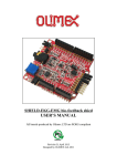
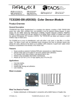
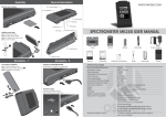
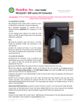
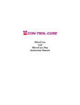
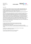
Color Sensor Module User Guide
Color Sensor Module Introduction
The Color sensor module base on TCS3200 which is a programmable color
light-to-frequency converter, it could filter RGB data from source light and
convert it to a square wave(50% duty cycle) with frequency directly
proportional to light intensity (irradiance). The full-scale output frequency can
be scaled by one of three preset values via two control input pins(SO, S1
Selectable Options 2%, 20%, 100% frequency),and pin S2, S3 control the filter
of RGB. Digital inputs and digital output allow interface to a microcontroller or
other logic circuitry directly. Output enable (OE) places the output in the
high-impedance state for multiple-unit sharing of a microcontroller input line. At
last, user can calculate the color of the light by RGB values.
Hardware and Software Preparation
Step1 Upload the Code
1.
2.
3.
4.
5.
Connect the Arduino UNO to PC with the Mini USB Cable.
Open the Arduino IDE1.0.X, and download code from our WIKI
If your IDE do not have TimerOne Library, please Download it from here
Choose the corresponding board and serial port
Compiling sketch until Done uploading appears
Step 2 Adjust the White Balance
1. We use TCS3200 chip for color sensor module.
2. The color sensor module power supply is from 3.27V to 5.5V
3. Connect the Arduino UNO and Color Sensor with Jumper Wire as below.
S0 connect to D6
S1 connect to D5
S2 connect to D4
S3 connect to D3
OUT connect to D2
VCC connect to VCC
GND connect to GND
OE connect to GND
4. Use white objects to perform white balance correction, after doing that, do
not move the color sensor module and light source to ensure the accuracy of
white balance value, therefore, we put the color sensor on the paper white part
like below.
5. Open Arduino IDE and click Serial Monitor and set the BaudRate as 9600
6. The Serial Monitor would display lots of parameter values, and we choose
some of them to explain to you.
� As the figure, the mark 1 is the RGB value at 1S period. The RGB value is
Red=1126 , Green=707 and Blue =774.
� Then the mark 2 is the scale factor.
� Then use the scale factor for adjusting the RGB value to 255 as Mark 3.
Step 3. Test colors with RGB value
1. The normal measurement distance is 0-2cm, so we put the color sensor
module on the paper another part.
2. Open the Serial Monitor, and now you have got the object’s RGB value like
(13 14 14 ), which means you have got the object color.
3.Open photoshop color picker, and the RGB value(13 14 14)means it is black.