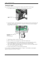
1
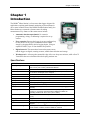
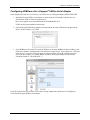
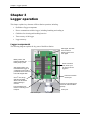
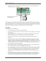
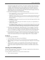
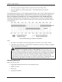
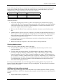
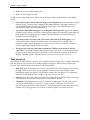
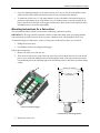
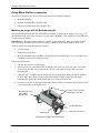
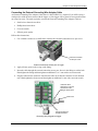
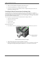
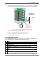
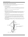
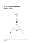
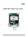
HOBO® Micro Station User’s Guide 7645-L Contact Information For support, please contact the company that you bought the product from: Onset Computer Corporation or an Onset Authorized Dealer. Onset Computer Corporation 470 MacArthur Blvd. Bourne, MA 02532 Mailing Address: P.O. Box 3450 Pocasset, MA 02559-3450 Phone: 1-800-LOGGERS (1-800-564-4377) or 508-759-9500 Fax: 508-759-9100 Customer Service Hours: 8AM to 5PM Eastern Time Technical Support Hours: 8AM to 8PM Eastern Time E-mail: [email protected] Main Onset Web site: www.onsetcomp.com WARNING: Fire, Explosion, and Severe Burn Hazard. Do not mix battery types, either by chemistry or age; batteries may rupture or explode. When replacing the batteries, read and follow their disposal instructions; dispose of lithium batteries according to local regulations. Do not dispose of batteries in fire. Never attempt to recharge a lithium or alkaline battery. Do not heat the batteries above 185°F (85°C). Do not mutilate or rupture the battery housing. Lithium batteries may explode if the logger is exposed to extreme heat or conditions that could damage or destroy the battery case. Do not expose the contents of the battery to water. WARNING: Severe shock hazard. Before installing tripod or mounting poles, ensure that there are no electrical power lines overhead. Do not install the system during any atmospheric electrical activity. Do not assemble or transport tripods, mounting poles, or other structures unless there is sufficient clearance from potential electrical sources or other obstructions. WARNING: Do not climb on or around the tripod (if using). The Micro Station and any of its associated hardware, towers, poles, etc. are not designed to support the weight of a person. Injury may result. WARNING: If using stakes to stabilize the tower, ensure that there are no underground wires or pipes under the Micro Station. WARNING: Do not use weather station as part of a critical control system. This system is not intended to be a fail-safe mechanism for anticipating life-threatening conditions, such as flash floods. © 2003–2014 Onset Computer Corporation, all rights reserved. Printed in the USA. Onset, HOBO, and HOBOware are registered trademarks of Onset Computer Corporation. Gore Vent is a trademark of W. L. Gore and Associates. All other trademarks are the property of their respective companies. ii HOBO Micro Station User’s Manual Table of Contents Chapter 1 Introduction................................................................................................................................ 1 Specifications ................................................................................................................................... 1 How to use this manual .................................................................................................................... 2 Smart sensors supported ................................................................................................................. 2 Chapter 2 Assembly and testing ............................................................................................................... 3 Items required .................................................................................................................................. 3 Logger and smart sensor setup instructions .................................................................................... 3 Testing the logger ............................................................................................................................ 6 Configuring HOBOware for a Keyspan® USB-to-Serial Adapter ..................................................... 7 Chapter 3 Logger operation ....................................................................................................................... 8 Logger components ......................................................................................................................... 8 Status lights ....................................................................................................................................... 9 Communicating with the logger ........................................................................................................ 9 Launching ........................................................................................................................................ 10 Selecting and installing batteries ................................................................................................... 11 Estimating battery life ...................................................................................................................... 12 Checking battery status ................................................................................................................... 13 Adding and removing sensors ....................................................................................................... 13 Time accuracy ................................................................................................................................ 14 Logger memory .............................................................................................................................. 15 Chapter 4 Field setup and mounting ....................................................................................................... 17 Guidelines for typical field setup .................................................................................................... 17 Guidelines for a tripod system setup ............................................................................................... 18 Guidelines for installing sensors ...................................................................................................... 18 Mounting instructions for a flat surface .......................................................................................... 19 Using Micro Station accessories .................................................................................................... 20 Mounting the logger with the Mast Mounting Kit .............................................................................. 20 Connecting the External Grounding Wire Adapter Cable ................................................................ 21 Connecting the External Communications Port Adapter Cable ....................................................... 22 Field preparation checklist ............................................................................................................. 23 Set up the tripod, cross arm, and sensors ..................................................................................... 26 Chapter 5 Troubleshooting ...................................................................................................................... 28 Chapter 6 Maintenance ............................................................................................................................. 30 Maintenance ................................................................................................................................... 30 Performing a visual inspection ......................................................................................................... 30 Cleaning the Micro Station .............................................................................................................. 30 Checking the desiccant pack ........................................................................................................... 31 Replacing the batteries .................................................................................................................... 31 Verifying the sensor accuracy.......................................................................................................... 31 HOBO Micro Station User’s Guide iii Chapter 1: Introduction Chapter 1 Introduction The HOBO® Micro Station is a four-sensor data logger designed for applications requiring multi-channel monitoring of microclimates in one or more locations. Part of the HOBO Weather Station family, the Micro Station uses a network of smart sensors for taking measurements. Key features of the smart sensors include: • Automatic detection upon launch. No extensive programming, wiring, or calibrating is required to set up sensors. • Easy expansion. Because the logger is not pre-configured, up to four sensors of any type or combination can be added simply by plugging them in before logging begins. Using an expansion chassis, up to 15 data channels are possible. • Digital network. The connections between the smart sensors and the logger are digital, ensuring accurate, reliable data collection and storage. • Weatherproof. A silicone gasket around the edge of the case keeps out moisture, while a Gore™ Vent allows the case to breathe while also keeping moisture out. Specifications HOBO Micro Station Operating Range Sensor Inputs Communication Dimensions Weight Memory Memory Modes Operational Indicators Logging Interval Battery Life Battery Type Time Accuracy Data Type Logger Start Modes Data Communication Environmental Rating -20° to 50°C (-4° to 122°F) with alkaline batteries, -40° to 70°C (-40° to 158°F) with lithium batteries Up to four smart sensors (including multiple-parameter sensors) 3.5 mm serial port or use serial-to-USB adapter cable (ADAP-SER-USB) to connect to a USB port on the computer 8.9 cm H x 11.4 cm D x 5.4 cm W (3.5 x 4.5 x 2.125 inches) 0.36 kg (0.8 lb) 512K nonvolatile flash data storage Stop when full, wrap around when full Seven lights provide logging and sensor network status 1 second to 18 hours, user-specified interval 1 year typical use (up to 4 sensors with 1 minute or longer logging interval) Four standard AA alkaline batteries included (for operating conditions -20° to 50°C [-4° to 122°F]); optional AA lithium batteries available for operating conditions of -40° to 70°C (-40° to 158°F) 0 to 2 seconds for the first data point and ±5 seconds per week at 25°C (77°F) Supports measurement averaging for select sensors Immediate, push-button, or delayed start options Current reading while logging, offload while logging, or offload when stopped TM Weatherproof, with Gore Vent and silicone gasket for deployment in harsh weather conditions, tested to NEMA 4x and IP66 HOBO Micro Station User’s Guide 1 Chapter 1: Introduction HOBO Micro Station Mounting Enclosure Access Sensor Network Cable Length Part Number Mount vertically on flat surface 18 cm (3.5 inches) or wider; optional mast mounting kit for use on 4.1 cm (1 5/8 inches) diameter masts Cover secured by four screws 100 m (328 ft) maximum H21-002 The CE Marking identifies this product as complying with all relevant directives in the European Union (EU). How to use this manual This manual covers the steps to set up, operate, and maintain the Micro Station, including: • Assembling the logger and perform an initial test • Operating the logger • Setting up the Micro Station in the field • Troubleshooting problems • Maintaining the Micro Station and getting service and support It is important that you test your system using the steps in Chapter 2 before continuing with other chapters in the manual and installing the Micro Station on site. Smart sensors supported The Micro Station supports a range of smart sensors, including: • Temperature • Temperature/relative humidity • Rain • Soil moisture • Wind speed • Wind direction • Barometric pressure (part # S-BPB-CM50 only) • Solar radiation • Photosynthetic active radiation (PAR) • 0-5 Volt Input Adapter • 4-20 mA Input Adapter • Pulse Input Adapter (contact closure and electronic switch) Refer to www.onsetcomp.com for a current list of compatible sensors. Refer to the manuals provided with the sensors for sensor specifications, mounting information, and recommended maintenance. 2 HOBO Micro Station User’s Manual Chapter 2: Assembly and testing Chapter 2 Assembly and testing The HOBO Micro Station is shipped partially assembled. This section explains how to assemble the logger, connect the smart sensors, and perform a quick test. Items required To configure the Micro Station you will need the following: • One to four smart sensors • Phillips-head screwdriver • Slotted screwdriver or small coin • Pen, pencil, or other blunt instrument • Adjustable 8 inch or 10 inch crescent wrench • Utility or pocket knife • PC interface cable (CABLE-PC-3.5) for serial ports; USB serial adapter (ADAP-SER-USB) if no serial port is available • Computer with logger software installed • Silicone grease tube Logger and smart sensor setup instructions 1. Insert four AA alkaline or lithium batteries. For more details on which type of batteries to use, see the Selecting and installing batteries section in Chapter 3 on page 11. 2. Place the battery strap on the batteries. Battery strap HOBO Micro Station User’s Guide 3 Chapter 2: Assembly and testing 3. With a crescent wrench, remove the dome nut from the stuffing gland in the sensor port. Dome nut Stuffing gland slit insert Stuffing gland on sensor port 4. Push the slit insert out from the inside of case. You may need to push the slit insert out using a pen (capped end), pencil (eraser end), or other blunt instrument. 5. Some sensors have an anti-snag device on the connector as shown below. If any of your sensors has this device, check that the connector fits through the stuffing gland. Anti-snag device on some external sensor connectors If the connector does not fit through the stuffing gland, you will need to trim the anti-snag device with a knife so that the connector looks like the one below. Anti-snag device removed from the external sensor connector 4 HOBO Micro Station User’s Manual Chapter 2: Assembly and testing 6. Insert the sensor connectors through the dome nut. The threaded side of the dome nut should be facing towards the connector. Then, slide the cables through the stuffing gland and through the hole in the case. Push the cables into the slit insert. Note: The electronics on some older temperature sensors are housed in a tube that is close to the sensor connector. If you have any of these sensors, be sure to insert them first because they will need more room inside the logger. Adjust the sensor as needed so that the tube with the electronics fits inside the logger without too much unnecessary bending of the cable. Stuffing gland on sensor port O-ring cord to fill empty holes Slit insert Dome nut Sensor cable and connector 7. Plug the sensors into the logger. Adjust the cable length as necessary so there isn’t excess cable inside the case. 8. If you are using fewer than four sensors, add the o-ring cord(s) to plug the empty hole(s) in the slit insert. 9. Apply some silicone grease to the slits on the insert. 10. Push the slit insert back into the stuffing gland. Pushing the slit insert in at a slight angle and with a slight twist may help it slide in more smoothly. 11. Screw the dome nut onto the stuffing gland, tighten by hand, and then an additional ½ to ¾ turn with an adjustable wrench. The dome nut must be snug, but shouldn’t be overtightened. 12. From the back side of the stuffing gland, fill the void inside with silicone grease from the package. 13. Remove the desiccant pack from its foil pouch and place inside the logger enclosure to minimize internal condensation. 14. Apply silicone grease to the outside rim of the case where the cover meets up with the housing. The grease should be applied sparingly in this location. 15. Screw the clear cover back onto the case. Use a Phillips-head screwdriver to tighten the four cover screws. HOBO Micro Station User’s Guide 5 Chapter 2: Assembly and testing Testing the logger It is recommended that you test the logger before setting it up in the field. To test the logger: 1. Use a slotted screwdriver or small coin to unscrew the data access port cover. Data access port cover 2. Insert the PC interface cable through the data access port and plug it into the communications port on the logger. If the computer does not have a serial port, refer to the next section on using the Keyspan USB-to-Serial Adapter. PC interface cable plugged into communications port 3. Using the logger software, select the Launch icon. 4. Make sure all the sensors you plugged in are visible in the Launch screen. 5. Choose a logging interval of a few seconds so that your test will yield enough data to look at. Select the Start Logging Now option, and click the Start button to launch the logger. 6. After a couple of minutes, read out the logger. You can choose to either stop the logger and read it out or let it continue logging while reading out. 7. Check the data and make sure it appears normal for all sensors. For more details on launching and logger operation, see Chapter 3. For information on mounting the logger and setting it up in the field, see Chapter 4. 6 HOBO Micro Station User’s Manual Chapter 2: Assembly and testing Configuring HOBOware for a Keyspan® USB-to-Serial Adapter If the computer does not have a serial port, you will need to use a Keyspan adapter (ADAP-SER-USB). 1. Install the Keyspan USB-to-serial adapter software from the CD included with the device or download the software from the Support tab at: http://www.tripplite.com/en/products/model.cfm?txtModelID=3914 Follow the Keyspan installation instructions. 2. Open the Keyspan USB Serial Adapter Assistant and the note the COM number assigned to the device. In this example, it is COM4. 3. Open HOBOware. From the File menu on Windows or from the HOBOware menu on Mac, select Preferences. Under Communications, click the arrow to open Device Types. Make sure “USB and serial devices” is selected. Click the arrow to open Serial Ports. Select the COM port noted in Step 2 (in this example, it is COM4). Note: On a Mac, the Keyspan adapter will be listed as something similar to “USA19H1d1P1.1.” Click OK in the Preferences window to save these settings. HOBOware should now be configured to work with the Keyspan USB-to-serial adapter. HOBO Micro Station User’s Guide 7 Chapter 3: Logger operation Chapter 3 Logger operation This chapter explains key elements of Micro Station operation, including: • Definition of logger components • How to communicate with the logger, including launching and reading out • Guidelines for selecting and installing batteries • Time accuracy of the logger • Logger memory Logger components The following diagram explains the key parts of the Micro Station. Status lights, see table in this section for details on each of the seven lights Battery holder, with batteries installed and battery strap in place Sensor connection ports, where up to four sensors can be plugged in Start logging button; use this button when logger is configured to launch with a push button start. Press and hold until all lights flash External connection access port Gore™ Vent, along with silicone gasket, allows case to breathe without allowing in moisture Connector for grounding wire and remote communications (optional) Communications port; used for connecting to a computer Sensor port Data access port 8 HOBO Micro Station User’s Manual Chapter 3: Logger operation Status lights There are seven lights on the Micro Station that indicate logger activity and status. The following table explains the function of these lights. This light: Blinks when: Notes Sensor Activity There is activity on the sensor network. The logger has been configured to launch at a specific date/time; will continue blinking until the defined start date/time. The logger has been configured to start with a push button start; will continue blinking until you press and hold the button on the logger for a couple of seconds. Every two seconds while the logger is recording data from sensors. The battery power is less than 25% capacity. Network activity is defined as communication from the logger to the sensor or vice versa. The logger will not record measurements while this light is blinking. Sensors can be added at this time. Delay Start Button Start OK Bat Low Mem Low Less than 25% of memory is available for saving data. Error There is or has been a sensor communication failure. The logger will not record measurements while this light is blinking. Sensors can be added at this time. Sensors cannot be added at this time. The logger will continue to run. However, you should read out the logger and then replace the batteries soon. The logger will continue to run until all memory is used. This light will only blink if the logger is configured to stop logging when memory fills. If this light is blinking in conjunction with the OK light, there was a communication failure. The system has recovered, but you may have an intermittent problem. If this is the only blinking light, then at least one sensor is currently not communicating. Immediate investigation is recommended. In general, it is recommended that you read out any data when this light is blinking, investigate the problem, and re-launch the logger. Communicating with the logger You can launch, read out, or check the status of the Micro Station with a computer or HOBO U-Shuttle (U-DT-1). 1. Use a slotted screwdriver or small coin to unscrew the data access port cover. Data access port cover HOBO Micro Station User’s Guide 9 Chapter 3: Logger operation 2. Insert the PC interface cable or shuttle cable through the data access port and plug it into the communications port on the logger. Cable plugged into communications port Once connected to the computer, use the logger software to configure the launch, read out the logger, or simply check the status. See the following sections for general information on launching and reading out. Refer to the HOBOware® user’s guide for detailed information. Refer to the HOBO U-Shuttle manual for instructions on launching, reading out, or checking status with a HOBO U-Shuttle. Launching To launch the logger with HOBOware: 1. Connect the logger to the computer and open HOBOware. 2. Select Launch from the Device menu or click the Launch icon on the toolbar to open the Launch Logger window. 3. In the Description field, type a description for the launch. This description will be used as the default file name when you read out and save the data recorded by the logger. 4. In the User Notes field, type up to 2,000 characters of information about the deployment (optional). 5. Select each sensor you want to include in the deployment. Only the sensors that are currently plugged in or built into the logger are listed. Sensors are listed in ascending order by serial number, regardless of their physical position in the logger. If you add or remove sensors, click the Refresh button to make sure your changes are seen by the logger and displayed in this list. 6. Type in a label for each sensor (optional). 7. Click the Filters button to create any additional filtered series, such as average temperature per day, automatically when you read out the logger and plot the data. 8. Select a logging interval, which is how often the logger will record data. You can choose either one of the preset logging intervals or specify a custom logging interval. The minimum logging interval is one second and the maximum for most loggers is 18 hours, 12 minutes, and 15 seconds. The shorter the logging interval, the more quickly memory fills and battery power is consumed. 9. Select a sampling interval, if applicable. The sampling interval allows you to take multiple measurements within the logging interval, then average them together to create a single logged measurement. The sampling interval is optional and is valid only for sensors that support 10 HOBO Micro Station User’s Manual Chapter 3: Logger operation measurement averaging. Refer to the sensor's user manual to determine whether measurement averaging is available on the sensor. If you have at least one sensor that supports measurement averaging, click the Enable button, then set the sampling interval at less than or equal to the logging interval (up to four minutes). Rapid sampling (faster than one minute) will reduce the logger's battery life. If you do not have any sensors with measurement averaging or wish to turn off the sampling interval, click the Disable button. 10. Select when to start logging. You can choose to launch the logger: • Now. Logging begins as soon as you click the Start button. If you do not have at least one sensor attached, the logger will not launch. • At Interval. Logging will begin at an exact interval (for example 9:00:00 rather than 8:47:00 when you choose a one-hour logging interval). The exact start time depends on the logging interval you choose. • Push Button. Logging will not start until you press the button on the logger and hold it down for at least three seconds. • On Date/Time. Logging will begin at a date and time you specify, up to approximately six months from the present. • Save Settings in Logger. Logging will not start, but the launch settings will be saved so that you do not have to re-enter them when you are ready to launch at a later time. The next time you view the Launch window for this logger, the settings you entered will still be in place. 11. Select when to stop Logging, either “when memory fills” or “never (wrapping).” If you select “when memory fills,” then the logger will stop recording data once the memory is full. If you select “never (wrapping),” the logger will record data continuously until either the logger battery runs out or you stop it. Once the logger is full, the newest data will overwrite the oldest data. 12. Click the Start button when you are finished choosing the launch settings. Note that the text on the Start button varies depending on when you chose logging to begin. HOBOware displays the progress of the launch and warns you not to unplug the logger while it is being configured. Reading out To read out the logger with HOBOware: 1. Connect the logger to the computer and open HOBOware. 2. Select Readout from the Device menu or click the Readout icon on the toolbar. If the Micro Station is logging, you can choose to either stop the logger before reading out or to let it continue logging. 3. After the readout is complete, you can plot the data. Note that readout speed depends on the method used to connect to the logger and the device being used. Typically, a readout via PC interface cable with the computer will take about six minutes for a full Micro Station (512K of data). Selecting and installing batteries The Micro Station requires four 1.5 volt AA batteries. The logger is shipped with four alkaline batteries, but it is also compatible with lithium batteries. For most applications, alkaline batteries are the preferred solution because: • They are relatively inexpensive HOBO Micro Station User’s Guide 11 Chapter 3: Logger operation • The battery gauge in the logger software will provide an accurate battery status • They have slightly more usable capacity than 1.5 Volt lithium batteries in temperate environments In cold applications (below 0°C [32°F]) and hot applications (above 40°C [104°F]), lithium batteries will generally outperform alkaline batteries. Alkaline batteries will still work in temperatures ranging from 40° to 50°C (104° to 122°F) and from -20° to 0°C (-4° to 32°F), however, they may not be the best choice. At temperatures lower than -20°C (-4° F) and higher than 50°C (122°F), alkaline batteries are unsuitable; use lithium instead. If the temperature is variable across the extremes, use lithium batteries. Use the following figure to help you choose the battery type based on the expected temperature range in your deployment. Lithium Alkaline = Recommended in this temperature range = Works in this temperature range, but not best choice Recommended battery type based on temperature Notes: • The logger is not designed to run with rechargeable or Carbon Zinc “Heavy Duty” batteries. • Using battery types other than 1.5 Volt alkaline or lithium may result in poor battery performance and erroneous battery state indication. WARNING: Fire, Explosion, and Severe Burn Hazard. Do not mix battery types, either by chemistry or age; batteries may rupture or explode. When replacing the batteries, read and follow their disposal instructions; dispose of lithium batteries according to local regulations. Do not dispose of batteries in fire. Never attempt to recharge a lithium or alkaline battery. Do not heat the batteries above 185°F (85°C). Do not mutilate or rupture the battery housing. Lithium batteries may explode if the logger is exposed to extreme heat or conditions that could damage or destroy the battery case. Do not expose the contents of the battery to water. Estimating battery life Battery life will vary with: 12 • Logging and sampling intervals in use (most important factor) • Number of sensors • Battery type • Operating environment HOBO Micro Station User’s Manual Chapter 3: Logger operation Use the following table to help you estimate how long the batteries will last (the run time) based on the logging interval. Note: The run times in this table assume that the recommended battery type for the temperature range is being used and up to four sensors are connected. Logging interval Sampling Interval Typical battery run time 1 second 1 minute 10+ minutes Off Off 1 minute 30 to 50 days About 12 months 12 months or more Additional guidelines: • Turn off the sampling interval unless you have sensors that support measurement averaging, which includes the 12-bit Temperature, Photosynthetically Active Radiation, and Solar Radiation smart sensors and the 4-20 mA and 0-5 Volt input adapters. Check the sensor manual to see if your sensor supports measurement averaging. • Make sure the “Use Before” date on the battery housing is at least two years from the current date. • Alkaline batteries will lose up to 10% of capacity a year sitting on a hot shelf and can lose up to 50% or more if “cooked” repeatedly (for example, stored on a car dashboard). Keeping batteries in the refrigerator can reduce self-discharge to 1 to 2% per year, however, be sure to avoid condensation forming on the batteries. • Use new batteries if you expect the deployment to require a substantial portion of battery life based on the table above. • Batteries are relatively inexpensive; don’t take a chance with suspect batteries. Checking battery status There are two ways to check the battery status of the logger: • Check the Bat Low light on the logger. This light blinks when the battery has 25% or less capacity remaining. • Check the status with logger software. For alkaline batteries, the status is displayed in the percentage of capacity remaining. Lithium battery voltage is either listed as “good,” which represents anywhere from 25 to 100% of capacity remaining, or “empty,” which represents 0 to 25% of capacity remaining. Lithium batteries have a relatively flat discharge curve, which means the voltage does not vary much with use until they fail. Because of the uncertainty in capacity, it is recommended that you start new launches with fresh lithium batteries that you know are at 100% rather than relying on old ones. It is always recommended that you read out the logger before replacing batteries. If you replace the batteries while the Micro Station is logging, it will stop recording data. The data will not be overwritten, however, until the next launch. Adding and removing sensors Smart sensors plug into the logger and collect data about various weather parameters. Before you bring the logger and sensors to the field, it is important that you gather and test all the sensors. Specifically, you should: • Plug in all the sensors you plan to use, HOBO Micro Station User’s Guide 13 Chapter 3: Logger operation • Make sure they are communicating, and • Make sure the readings are valid. To add a sensor, simply plug it into a sensor port on the logger. Follow these guidelines when adding sensors: • Never add or remove sensors while the logger is recording data. Sensors should only be added while the logger is stopped, when configuring the launch parameters with logger software, or after configuration but before the start of logging (if the logger was configured to start on a specific date or time or by a push button start). • Any sensors added while the logger is recording data will be ignored. Logging will continue normally for other sensors. If a sensor is removed while logging, the Sensor Error status light will blink when the next logging interval is reached. The data for that sensor will then display as missing or erroneous in readouts. • You cannot replace one sensor with a new sensor of the same type while logging. If you would like to replace a sensor with another sensor of the same type (for example, swap a temperature sensor with a new temperature sensor), it is necessary to read out the current data from the logger and re-launch with the new sensor. • The logger can work with a maximum of 100 meters (328 feet) of smart sensor network cable, which is the digital communications portion of the sensor cables. If you are using multiple sensors, be sure to check the length of each smart sensor network cable reported in the Sensor Manuals. Add them together and make sure they do not exceed 100 meters (328 feet). Time accuracy Upon launch, the Micro Station’s clock is set in Coordinated Universal Time (UTC), which is determined from the clock on your computer. Once the Micro Station is logging, it will keep fairly accurate time. However, there are three main sources of errors with time reporting. 14 • Host clock error. A common source of error is an incorrect time in the computer used to launch the logger. Make sure the clock on your computer is set to the correct date and time before launching the logger. One resource for calculating accurate time settings for UTC (colloquially known as Greenwich Mean Time or GMT) is the www.time.gov web site. • Start-up error. The logger can lose as much as 2 seconds when it is launched. This is a one-time error that occurs as part of the start-up sequence and cannot be avoided. • Clock drift. The long-term time accuracy is a function of temperature. The worst-case error is ±8 parts per million (PPM) a week at 25°C, which is about 5 seconds per week. The error increases as the temperature deviates from 25°C (see the figure below). If the temperature were a constant -20°C, the logger time error could be as much as 35ppm (21 seconds per week). HOBO Micro Station User’s Manual Chapter 3: Logger operation Worst case time error Reading out the logger and relaunching it will reset the logger’s clock. This is useful when your logger has been running for a while and its clock needs to be reset. Just be sure the computer clock is set accurately before relaunching. Logger memory The logger uses non-volatile memory, which means it retains data indefinitely once power runs out. Specifically, the logger uses a high-capacity Flash memory to store data, which can retain the data even when the batteries are removed. This type of memory is very durable. If the logger dies in the field from dead batteries, replace them and read out the logger immediately. Do not relaunch the logger until the data has been recovered. If your logger is damaged, contact Onset Computer because there is a chance the data can be recovered. Refer to Chapter 6 for information about returning loggers for data recovery. The logger contains 512K bytes of memory. Up to 10K of this memory is used to store the launch configuration and deployment notes, leaving at least 502K bytes for data storage. The logger software automatically estimates how long the logger will record data until the memory is full (the run time) based on the logging interval and the number and type of sensors connected. In general, adding sensors decreases running time while increasing the logging interval increases running time. In most applications, battery life limits the duration of the data logging before memory capacity. The following figure shows the expected run time for several logging intervals based on the total number of bits in place, which is determined by adding together the bits per sample for each sensor measurement parameter in your system. For example, a Micro Station with the following sensors is using 56 total bits. 1 Temperature X 8 = 8 1 Wind Speed X 16 = 16 2 Temperature/RH X 16 = 32 Total number of bits HOBO Micro Station User’s Guide 56 15 Chapter 3: Logger operation At a logging interval of 5 minutes, the memory run time for a Micro Station using 56 bits would be approximately 250 days (based on the following figure). See the sensor’s manual for the number of bits each type of sensor uses. Memory run time 16 HOBO Micro Station User’s Manual Chapter 4: Field setup and mounting Chapter 4 Field setup and mounting This chapter explains how to set up the Micro Station in the field, both with and without the optional accessories. This includes: • Guidelines for typical field setup • Mounting instructions • Using Micro Station accessories • Tripod setup Guidelines for typical field setup Use the following guidelines to help you choose an appropriate site for setting up the Micro Station and protecting against field hazards. • WARNING: Severe shock hazard. Do not set up the HOBO Micro Station near power lines. Contact between the HOBO Micro Station and power lines may result in a fatal shock, electrocution, or death. • IMPORTANT: The logger must be mounted vertically so that cables hang down (preventing moisture from entering the connection) and to allow for proper ventilation of the case through the Gore Vent. • Avoid placing the logger in extremely hot locations (such as on a dashboard or the roof of a greenhouse) and chronically wet locations (such as in a well or any place that is wet most or all of the time). Also avoid rising water and flood zones. • Mount the logger so that it faces away from the sun (facing north in the northern hemisphere) to avoid the sun causing excessive internal heating. • Conduit is recommended when placing a sensor in or near the ground to protect against animals, lawn mowers, tractors, exposure to chemicals, etc. • Beware of rodents, birds, cattle, and other animals that can bite, peck, or trample the Micro Station. • An External Grounding Wire Adapter Cable (Part # CABLE-HWS-G) is required if you will be using a wind speed or wind direction sensor with the logger. Both an External Grounding Wire Adapter Cable and a Grounding Kit (Part # M-GKA) are recommended if the logger will be placed in an exposed location on a tripod or tower. • If possible, avoid sites immediately adjacent to radio/television/microwave towers and equipment. In rare situations, strong electromagnetic interference may result in sensor network errors. • Take note of the mounting considerations in the Sensor Manuals for additional guidelines relative to the particular sensors you are using. • If mounting the logger to a post or wall, note that it is 60 x 103 mm (2.37 x 4.06 inches) between the center of the holes on the back of the logger. See Figure 10 on page 18. HOBO Micro Station User’s Guide 17 Chapter 4: Field setup and mounting • Onset offers a 1.5 meter mast (Part # M-MPB), which is especially useful when you are trying to minimize the size and visibility of the Micro Station. Guidelines for a tripod system setup In addition to the guidelines above, adhere to the following guidelines for using the Micro Station with a tripod: • If you will be using a rain gauge or wind sensor, select a location away from trees and buildings. Place the rain bucket at a distance away from obstructions that is equal to at least three times the height of the nearest tree, building, or other obstruction, and the wind speed or wind direction sensor at a distance away from obstructions that is equal to at least five times the height of the obstruction. • WARNING: Severe shock hazard. Do not set up the Micro Station near power lines. Contact between the Micro Station and power lines may result in a shock, electrocution, or death. • For areas with winds greater than 50 mph, to stabilize a tall mast, or if the rain gauge is attached to the top of the mast, use the Guy Wire Kit (Part # M-GWA) and 1/2 inch Stake Kit (Part # MSKA) to secure the system. • Either an External Grounding Wire Adapter Cable (Part # CABLE-HWS-G) or an External Communications Port Adapter Cable (Part # CABLE-HWS-F) is required if you will be using a wind speed or wind direction sensor with the logger or if the logger will be placed in an exposed location. In addition, the Grounding Kit (Part # M-GKA) is recommended if the logger will be outdoors in an exposed location. Electrically ground the logger to its mounting mast, which in turn must be connected to a ground rod to reduce the chance of damage from atmospheric electrical activity. • 2 meter Tripod Tower Assembly (Part # M-TPB): You must set up the tower on level ground; there should be no ground slope. The legs on the 2 meter tower are non-adjustable. If the site you are using is not level, then you will need to either level it or use shims to level the tripod. Be prepared to dig if necessary. Suggested Mounting: Use 1/4 inch Stake Kit (Part #M-SKB). • 3 meter Tripod Tower Assembly (Part # M-TPA): The maximum ground slope is 13 degrees. The legs on the 3 meter tower allow for limited adjustment on uneven ground. Be prepared to dig if necessary if the slope is significant. Suggested Mounting: Use 1/2 inch Stake Kit (Part # MSKA). • It is recommended that two people set up most tripod systems. Some assemblies are heavy and are easier to handle with two people. • Be sure to stabilize, level, and secure the tripod on firm ground. It may be necessary to adapt the installation to the existing site conditions as necessary (for example, if mounting the tripod on ice or rock, you may need to use a masonry clamp to secure it). Guidelines for installing sensors 18 • If running cables along the ground, we recommend running them through conduit to protect them from animals (some animals like to chew on the cables), lawn mowers, and being tripped on. • For information on protecting the sensors properly, refer to the Sensor Manuals. • Leave enough slack in the cables so that they can be routed into the logger. HOBO Micro Station User’s Manual Chapter 4: Field setup and mounting • If you are deploying multiples of the same sensor type, be sure to note the serial number on the cable associated with each measurement location so you can interpret the data later. • To mount the 4-20 mA or 0-5 Volt input adapters, use the self-adhesive hook-and-loop tape to mount the input adapter on top of the battery cover. If another sensor is already mounted on the battery door, then use the back of the logger enclosure door. Refer to the sensor manual for more information on how to use the input adapter. Mounting instructions for a flat surface You can mount the Micro Station to a flat surface without any optional accessories. IMPORTANT: The logger must be mounted vertically so that cables hang down (preventing moisture from entering the connection) and to allow for proper ventilation of the case through the Gore Vent. To mount the logger to a flat surface, such as a 2x4 pressure-treated stud or plank, you will need: • Phillips-head screwdriver • Four Phillips-head screws (shipped with logger) Follow these instructions: 1. Remove the clear cover from the case. 2. There are four holes next to each of the four screw holes used to attach the clear cover as shown below. Screw in the four Phillips-head screws through the inside of the case into the flat surface. Use the dimensions in the following figures for determining where to drill holes on the mounting surface. 90 mm (3.5 inches) 114 mm (4.5 inches) 103 mm (4.06 inches) 60 mm (2.37 inches) Holes for mounting logger Dimensions for mounting pattern 3. Replace the clear cover. HOBO Micro Station User’s Guide 19 Chapter 4: Field setup and mounting Using Micro Station accessories This section explains how to use the following accessories with the Micro Station: • Mast Mounting Kit • External Grounding Wire Adapter Cable • External Communications Port Adapter Cable Mounting the logger with the Mast Mounting Kit An optional Mast Mounting Kit (Part # M-MKA) is available for mounting the logger to a 4.1 cm (1 5/8 inch) diameter mast, such as the optional 1.5 m mast (Part # M-MPB), or 2 m tripod (Part #-M-TPB) and 3 m tripod (Part # M-TPA). IMPORTANT: The logger must be mounted vertically so that cables hang down (preventing moisture from entering the connection) and to allow for proper ventilation of the case through the Gore Vent. The tools required to mount the logger to a mast are: • 1/2 inch wrench • Phillips-head screwdriver • Mast Mounting Kit (Part # M-MKA), which includes one mounting plate, two 1-5/8 inch U-bolt assemblies, and four 6x38 flat head screws. Follow these instructions: 1. Unscrew the clear cover on the logger. 2. Place the four screws provided in this kit through each of the four holes next to the screw holes used to attach the clear cover. Screw in the four screws through the inside of the case to the mounting plate. 3. Using the two 1-5/8 inch U-bolt assemblies and the mounting plate, mount the logger upright to the mast. Place the U-bolts around the mast and install the saddle clamps. Place the logger mounting plate against the saddle clamps and screw on the U-bolt hex nuts. 4. Screw the cover back on the logger when done. Make sure there is adequate silicone grease on the cover gasket before replacing the cover. Insert four screws in holes to mount logger to the plate Mounting plate from optional Mast Mounting Kit U-bolt saddle clamp U-bolt hex nut U-bolt (mast not shown) Mounting the logger with the Mount Kit 20 HOBO Micro Station User’s Manual Chapter 4: Field setup and mounting Connecting the External Grounding Wire Adapter Cable An External Grounding Wire Adapter Cable (Part # CABLE-HWS-G) is required if you will be using a wind speed or wind direction sensor with the logger or if the logger will be placed in an exposed location on a tripod or tower. The tools required to connect the External Grounding Wire Adapter Cable are: • Small coin or slotted screwdriver • Phillips-head screwdriver • Crescent wrench • Silicone grease packet Follow these instructions: 1. Use a slotted screwdriver or small coin to unscrew the external connection access port cover. External connection access port cover External connection access port on logger 2. Apply silicone grease to the o-ring on the fitting. 3. Insert the cable through the external connection access port. Screw in the fitting to seal the hole. Hand-tighten the fitting and then tighten an additional ½ to ¾ turn with a crescent wrench. 4. Plug the cable into the connector. Note that the cable can fit into the connector in one direction only. Hand-tighten the dome nut and then tighten an additional ½ turn with a crescent wrench. Insert the cable through the hole and then screw in this fitting as shown here Dome nut Plug grounding wire into this connector Grounding wire plugged into logger HOBO Micro Station User’s Guide 21 Chapter 4: Field setup and mounting 5. Fill the void in the backside of the gland nut with silicone grease. 6. Connect the grounding wire to a clamp on the mast or tripod. 7. Screw the cover back on the logger. Make sure there is adequate silicone grease on the cover gasket before replacing the cover. Connecting the External Communications Port Adapter Cable An optional External Communications Port Adapter cable (Part # CABLE-HWS-F) is available for connecting the logger to a serial extension cable. This cable includes a grounding wire, which is required if you will be using a wind speed or wind direction sensor with the logger or if the logger will be placed in an exposed location on a tripod or tower. The tools required to connect the External Communications Port Adapter Cable are: • Small coin or slotted screwdriver • Phillips-head screwdriver • Crescent wrench • Silicone grease packet Follow these instructions: 1. Use a slotted screwdriver or small coin to unscrew the external connection access port cover. External connection access port cover External connection access port on logger 2. Apply silicone grease to the o-ring on the fitting to be inserted. 3. Insert the cable through the external connection access port. Screw in the fitting to seal the hole. Hand-tighten the fitting and then tighten an additional ½ to ¾ turn with a crescent wrench. 22 HOBO Micro Station User’s Manual Chapter 4: Field setup and mounting 4. Plug the cable into the connector. Note that the cable can fit into the connector in one direction only. Hand-tighten the dome nut and then tighten an additional ½ turn with a crescent wrench. Insert the cable through the hole and then screw in this fitting as shown here Dome nut External communications port connector; plug in adapter cable here External communications port adapter cable plugged into logger 5. Fill the back side of the gland nut with silicone grease. 6. Connect the communications end of the cable to the serial cable. 7. Connect the grounding wire to a clamp on the mast or tripod. 8. Screw the cover back on the logger. Field preparation checklist Use the following checklist to make sure you have all the necessary materials for setting up a Micro Station with accessories from the HOBO Weather Station family of products. Task Check that you received all the parts for your Micro Station system as ordered. Configure the logger. Set up the logger for launch; install batteries and battery strap. For details, see Chapters 2 and 3. If you are using the External Grounding Wire Adapter Cable or External Communication Port Adapter Cable, install them now. See the instructions on pages 21 and 22. If you opened any parts: Double-check the packing lists to make sure you haven’t lost any pieces. If you are using the Mast Mounting Kit, mount the logger now. See the instructions on page 20. If you are using the Solar Radiation Shield: Set up the Temperature and Temperature/RH sensors. There are several small pieces required to connect these sensors to the shield that could easily get lost in the field. It is strongly recommended you install these sensors in the solar HOBO Micro Station User’s Guide 23 Chapter 4: Field setup and mounting Task radiation shield before going to the field. See the solar radiation shield manual. Repack the logger and sensors for transit. It is strongly recommended that you use the original packaging when possible because it is custom-designed to protect the Micro Station and its components. Gather the tools required for setup. Use the following checklists to make sure you have the necessary tools to set up the Micro Station in the field. The items marked “optional” depend on your site needs. Logger Item Rain Gauge Sensor Phillips-head screwdriver Item Adjustable 8 inch or 10 inch crescent wrench (if using mast mounting kit) Pen, pencil, or other blunt instrument Small coin or slotted screwdriver Utility or pocket knife Mast level (Part # M-MLA) (optional; for mounting on separate mast) Sledgehammer or post driver (optional; for mounting on separate mast) Eye protection—safety glasses (if using sledgehammer/post driver) Slotted screwdriver Conduit (optional) Light Sensor Wind Speed or Wind Direction Sensor Item Item 7/16 inch wrench Ladder (if deploying sensor above eye level) Light sensor level (Part #M-LLA) Crescent wrench (or second 7/16 inch wrench) 1.06 inch/2.00 inch hose clamps (if mast mounting without cross arm) Phillips head screwdriver #1 Compass Gather the tools required for setup (continued) Soil Moisture Sensor Item Temperature/RH or Temp Sensor Trenching shovel, spade, or flat bar Item Water (optional) Phillips head screwdriver #1 (if sensors are not already installed) Conduit (optional) 4-20 mA Input Adapter Pulse Input Adapter Item Hook and loop tape Item Two wire nuts 0-5 Volt Input Adapter Item 24 HOBO Micro Station User’s Manual Chapter 4: Field setup and mounting Task Hook and loop tape 3 m or 2 m Tripod with Mast (M-TPA or M-TPB) Item Cross Arm (M-CAA) or (M-CAB) Item 1/2 inch wrench Mast level (Part # M-MLA) Medium size wire cutters Crescent wrench 1/2 inch wrench Crescent wrench Redimix cement (optional) Stake Kit (M-SKA) or (M-SKB) Shovel (optional) Item All purpose grease Tape measure Tie wraps Sledgehammer Eye protection—safety glasses 3 m Mast (M-MPA) 1.5 m Mast (M-MPB) Item Item 1/2 inch wrench Sledgehammer or post driver Eye protection—safety glasses (if using sledgehammer/post driver) Mast level (Part # M-MLA) Redimix cement (optional) Shovel (optional) All purpose grease Tape measure Sledgehammer or post driver Eye protection—safety glasses Mast level (Part # M-MLA) Grounding Kit (M-GKA) Guy Wire Kit (M-GWA) Item Item Phillips head screw driver #2 1/2 inch wrench Medium size wire cutters Crescent wrench Solar Radiation Shield (M-RSA) Light Sensor Bracket (M-LBB) 1/2 inch wrench Phillips head screwdriver #1 (if sensors aren’t already installed) HOBO Micro Station User’s Guide Redimix cement (optional) Shovel (optional) All purpose grease Tape measure 1/2 inch wrench Sledgehammer Eye protection—safety glasses Medium size wire cutters Item Item 1/2 inch wrench 25 Chapter 4: Field setup and mounting Set up the tripod, cross arm, and sensors You can mount the HOBO Micro Station on a tripod with a cross arm. Follow this general procedure. Refer to the Tripod Setup Guide and sensor manuals for detailed steps. 1. Set up the tripod lower mast. 2. Install the grounding kit. 3. Before installing the upper mast on the tripod, consider attaching the cross arm and sensors that will go at the top of the mast as it will be easier to mount them while the upper mast is lower to the ground. 4. Install any other smart sensors and solar radiation shield, if applicable. 5. Mount the upper mast to the lower mast 6. Mount the logger to the upper mast. Position the logger enclosure so that it will not be in the way of the guy wires. If you are using the External Grounding Wire Adapter Cable or External Communications Port Adapter Cable, attach the grounding wire to the mounting plate U-bolt. 7. Install the guy wire kit 8. Set the final position of all sensors and plug them into the logger if you haven’t already done so. Check that the batteries are securely seated in their holder with the battery strap in place. 9. Use cable ties to secure all sensor cables to the cross arm, bracket, mast, and tripod legs. The sensor cables should run below the cross arm and brackets to minimize the chance of birds pecking and damaging the cables. Cable ties should be spaced no more than .3 m (1 foot) apart. Some examples are: 10. Gather the excess cable and attach the cable ties to the upper mast behind the logger. Leave about a 5 cm (2 inch) drip loop of cable below the logger. All cables should be neatly secured to the mast when complete. Sensor cables Cable ties Mounting plate from Mount Kit Drip loop 26 HOBO Micro Station User’s Manual Chapter 4: Field setup and mounting 11. Recheck that all the U-bolts, nuts, and clamps are secure for the entire system. 12. The logger is ready to begin logging. • If you configured the logger to launch with a push button start, the Button Start light should be blinking. To start logging, press and hold the button inside the logger enclosure for a second until all lights flash (the logger cover must be off to access the button). • If you configured the logger to start on a specific date/time, the Delay Start light should be blinking. The logger will start automatically at the date/time you entered. • If you did not set up the logger with a button or delayed start, connect the logger to the computer to launch it. See Chapter 3 for details on connecting to the logger and launching. 13. Once the logger is launched, make sure the OK status light is blinking. This indicates the logger is recording data properly. You may need to cup your hand over the top of the logger to see the lights in full sunlight. 14. Screw on the logger cover if you removed it earlier, making sure the desiccant pack is inside the logger enclosure to minimize internal condensation (remove desiccant pack from its foil pouch before installing). Make sure all logger openings are covered and the sensor dome nut is secure. HOBO Micro Station User’s Guide 27 Chapter 5: Troubleshooting Chapter 5 Troubleshooting The following chart lists common problems you may encounter with the HOBO Micro Station and possible resolutions. Problem Resolution Individual sensors are not found or are missing in the Launch Logger window in HOBOware • If a sensor is removed and then immediately re-inserted, it may not be auto-detected and therefore will not appear in the Launch Logger window. Click the Refresh button in the Launch Logger window. • Check for a loose connection between the sensor and the logger. • Make sure you haven’t exceeded 100 meters (328 ft) of network cable. All sensors are missing in the Launch Logger window in HOBOware Remove all but one sensor, then check if the sensor appears in the Launch Logger window. Continue to remove and re-insert the sensors one at a time until you find the bad sensor. If you find a bad sensor or if none of the sensors communicate, contact your Onset dealer or Onset Computer Corporation. The error status light is blinking • If the error light is blinking in conjunction with the OK light, there was a communication failure. The system has recovered, but you may have an intermittent problem. Try checking the sensors one at a time to make sure they are all communicating. If you find a bad sensor or if no sensor communicates, contact your Onset dealer or Onset Computer Corporation. • If the error light is the only light blinking, then at least one sensor is currently not communicating. Immediate investigation is recommended. Look for a loose connection, which could cause bad electrical contact with a sensor. If found, remove the offending sensor and check its wires and connector for damage and/or signs of moisture. • In general, it is recommended that you read out any data when this light is blinking, investigate the problem, and re-launch the logger. • Check the polarity; make sure the batteries are installed properly. It is possible one cell is reversed. • Make sure you aren’t using a combination of alkaline and lithium batteries. Never mix battery types. • Check the battery expiration date; make sure it is at least two years from the current date. Batteries can lose significant capacity if stored at elevated temperatures. • Check the voltage with a voltmeter. Alkaline batteries should be at least 1.5 volt per cell when new; lithium batteries should be 1.6 volt per cell. The battery low light is blinking after the batteries were replaced 28 HOBO Micro Station User’s Manual Chapter 5: Troubleshooting Problem Resolution Batteries die prematurely • Check for excessive moisture in the logger enclosure. Severe and/or repeated condensation in the logger enclosure can lead to short circuits and battery failure. It may be necessary to add additional sealing and/or desiccant to the logger enclosure to prevent condensation. • Check to make sure that both the logging and sampling intervals are set for at least 1 minute or greater. Sampling/Logging intervals faster than 1 minute will rapidly deplete the battery. See the section on Estimating battery life for more details. • Check for damaged wiring and/or sensors. Damaged cables or connectors can result in complete or partial sort circuits that will rapidly drain batteries. • The lights are very faint. In direct sunlight, shield the sun and check again. • Make sure the batteries are not dead. Batteries should have at least 1 volt per cell. • The memory may be full. Read out (offload) data from the logger and relaunch. • The logger may not have been launched. Check the status with the logger software. No status lights are flashing OK status light is not flashing Make sure the logger is launched. If you configured the logger to start logging on a specific date/time, check the date and time you selected and make sure the Delay Start light is flashing. If you configured the logger to launch with a push button start, press and hold the button on the logger for a second until all the lights flash. Data file contains errors If you are missing data for a particular sensor, check that the sensor was properly installed. Remove and re-insert the sensor, and check that it can take current readings. If you find that it is not communicating, it may be a bad sensor. Contact your Onset dealer or Onset Computer Corporation. Data file can’t be opened The data file may have become corrupted. In rare circumstances, the data file may have errors. Offload the logger again and try opening the file again. If that does not work, contact your Onset dealer or Onset Computer Corporation. Logger is not found • Check and replace the batteries. • Check communications cable connections. HOBO Micro Station User’s Guide 29 Chapter 6: Maintenance, support, and service Chapter 6 Maintenance This chapter explains: • Recommended maintenance for the Micro Station Maintenance Regular maintenance on the HOBO Micro Station is essential because it extends the life of the components and helps to ensure the accuracy of recorded measurements. When the Micro Station is deployed in the field, potential damage can come from numerous sources, such as rodents, birds, vandals, and heavy storms. Periodic check-ups in the field allow you to: • Check that the station is still set up and functioning as you intended • Check for damage • Minimize the impact of any damage found This is particularly important if the Micro Station is being deployed for a long period of time, such as several months or a year. Regular checkups will help ensure that you are continuing to gather data as expected. Performing a visual inspection Periodically perform a visual inspection of the Micro Station tower and logger enclosure. Check that: • Cables and wires are not damaged, cracked, cut, split, or broken • All the screws and bolts are tightly secured • The mast is still level (if in use) • The ground attachments are fastened to the tripod and logger (if in use) • There is no excess rust; replace rusty parts as necessary Cleaning the Micro Station The logger enclosure does not require regular cleaning. However, it is recommended that in dusty locations you regularly clean these items: 30 • Solar radiation shield. Wash with soap and water. Dirt/cobwebs obstruct air flow. Discoloration can cause increased solar absorption, which can result in increased errors. Do not get the temperature/RH sensor wet; see the temperature/RH sensor manual for instructions on cleaning it. • Light sensor. Make sure the drain hole is not plugged. If you need to clean the sensor head, see the sensor manual for details and cautions on proper cleaning. • Rain gauge. Make sure there are no leaves or debris in the collector. Make sure the funnel is not plugged; use a cotton swab if necessary to clean. HOBO Micro Station User’s Manual Chapter 6: Maintenance, support, and service • Anemometer on wind speed sensor. Make sure the cups do not have any dirt/dust/cobwebs. Clean if necessary. • Logger enclosure. Remove dust with compressed air. Do not get water inside the enclosure. • Tower. Hose with fresh water if necessary. Checking the desiccant pack The desiccant pack included with the Micro Station is an indicating desiccant pack, which means it changes color from blue to pink when it is no longer absorbing moisture. If the desiccant pack is blue, it is still good. If it is pink, it is bad and needs to be reconditioned. To recondition a desiccant pack, place it in a warm, dry spot until it turns blue. For example, place the desiccant pack in an oven set to 50 to 70°C (122 to 158°F) for 24 hours. Once it turns blue again, you can place it back in the logger. If the desiccant pack is pink, also check for condensation within the logger. If there is condensation, check that the fittings are still tight and secure and the cover’s rubber gasket is clean and has an even coating of silicone grease, or consider moving the logger to a drier location. Replacing the batteries Batteries are cheap insurance. Replace them at least once a year to prevent any loss of data. Be sure to read out the logger before replacing the batteries. For more details, refer to the Selecting and installing batteries section in Chapter 3. Verifying the sensor accuracy For most sensors, it is recommended that you test sensor measurement accuracies once a year. Onset Computer can verify the accuracy of all sensors and recalibrate some sensors. For more details on verifying sensor accuracy, refer to the Sensor Manuals included with the sensors. HOBO Micro Station User’s Guide 31