1
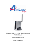
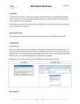
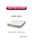
300N Multi-Function Wireless Router
Model # AR686WV2
User’s Manual
Ver. 1A
Copyright
Copyright © Airlink101, 2014. The contents of this publication may not be reproduced in
any part or as a whole, stored, transcribed in an information retrieval system, translated
into any language, or transmitted in any form or by any means, mechanical, magnetic,
electronic, optical, photocopying, manual, or otherwise, without the prior written
permission.
Trademarks
All products, company, brand names are trademarks or registered trademarks of their
respective companies. They are used for identification purpose only. Specifications are
subject to be changed without prior notice.
FCC Interference Statement
This equipment has been tested and found to comply with the limits for a Class B digital
device pursuant to Part 15 of the FCC Rules. These limits are designed to provide
reasonable protection against radio interference in a commercial environment. This
equipment can generate, use and radiate radio frequency energy and, if not installed and
used in accordance with the instructions in this manual, may cause harmful interference
to radio communications. Operation of this equipment in a residential area is likely to
cause interference, in which case the user, at his own expense, will be required to take
whatever measures are necessary to correct the interference.
Table of Contents
COPYRIGHT ..............................................................................................................................................................2
FCC INTERFERENCE STATEMENT .....................................................................................................................2
CHAPTER 1 PRODUCT INFORMATION ..............................................................................................................1
1.1 INTRODUCTION AND SAFETY INFORMATION .............................................................................................. 1
1.2 PACKAGE CONTENTS ............................................................................................................................. 2
1.3 FAMILIAR WITH YOUR NEW GREEN ROUTER ............................................................................................ 3
CHAPTER 2 CONFIGURE THE ROUTER ............................................................................................................5
2.1 CONNECT THE ROUTER TO YOUR NETWORK ............................................................................................ 5
2.2 CONFIGURE THE ROUTER WITH QUICK SETUP......................................................................................... 7
2.2.1 INTERNET CONNECTION TYPE ............................................................................................................. 8
2.2.2 W IRELESS SETUP............................................................................................................................... 9
2.3 CONNECT TO ROUTER W IRELESSLY ..................................................................................................... 10
CHAPTER 3 ADVANCED ROUTER CONFIGURATION .................................................................................. 11
3.1 STATUS ............................................................................................................................................... 12
3.2 NETWORK ........................................................................................................................................... 12
3.2.1 WAN .......................................................................................................................................... 13
3.2.2 LAN ............................................................................................................................................ 19
3.2.3 IPTV ........................................................................................................................................... 21
3.2.4 Address Reservation ................................................................................................................. 21
3.2.5 Operation Mode ......................................................................................................................... 23
3.3 W IRELESS........................................................................................................................................... 23
3.3.1 Wireless Settings ....................................................................................................................... 24
3.3.2 MAC Filtering ............................................................................................................................. 33
3.3.3 WPS Setting .............................................................................................................................. 35
3.3.4 Multiple SSID ............................................................................................................................. 37
3.4 BANDWIDTH CONTROL ......................................................................................................................... 39
3.5 FORWARDING ...................................................................................................................................... 42
3.5.1 Virtual Server ............................................................................................................................. 42
3.5.2 DMZ ........................................................................................................................................... 44
3.5.3 UPnP ......................................................................................................................................... 46
3.5.4 Port Triggering ........................................................................................................................... 46
3.6 ACCESS CONTROL .............................................................................................................................. 46
3.6.1 IP Filtering ................................................................................................................................. 47
3.6.2 MAC Filtering ............................................................................................................................. 50
3.6.3 Domain Filtering ........................................................................................................................ 52
3.7 DYNAMIC DNS .................................................................................................................................... 54
3.8 SYSTEM TOOLS ................................................................................................................................... 56
3.8.1 Firmware Upgrade ..................................................................................................................... 56
3.8.2 Backup & Restore ..................................................................................................................... 57
3.8.3 Diagnostic Tools ........................................................................................................................ 58
3.8.4 Remote Management ................................................................................................................ 59
3.8.5 Time Settings ............................................................................................................................. 60
3.8.6 Password ................................................................................................................................... 60
3.8.7 Statistics .................................................................................................................................... 62
3.8.8 System Log................................................................................................................................ 63
3.8.9 System Restart .......................................................................................................................... 63
3.8.10 Factory Default ........................................................................................................................ 63
CHAPTER 4 APPENDIX ......................................................................................................................................... 64
4.1 HARDWARE SPECIFICATION.................................................................................................................. 64
TECHNICAL SUPPORT .......................................................................................................................................... 65
Chapter 1 Product Information
1.1 Introduction and safety information
Congratulations on your purchase of the Airlink101® AR686WV2 Wireless N 300 Green
Router. This Router is recommended to be used with AirLink101® Wireless N 300
products to provide the best performance. The high bandwidth combined with extended
wireless coverage delivers fast and reliable connections for all of your networking
applications. The built-in gigabit switch highly increases the wired Ethernet speed.
The Green power saving technology intelligently reduces power consumption when no
network activity is detected. A full range of security features such as WEP, WPA-PSK,
and WPA2-PSK provide the highest level of wireless network security. The bundled EZ
Setup Wizard allows you to set up the router with an easy-to-use user interface. Best of
all, AR686WV2 works with all 802.11n / g / b network devices which ensures
compatibility with the existing wireless products.
Other features of this router including:
•
Support high wireless data rate of up to 300Mbps* with 802.11n standard
•
Built-in 4-port full-duplex 10/100Mbps Switch to connect your wired network up to
Fast Ethernet speeds, with cable length and link down power saving
•
•
•
Support virtual server, ALG, DMZ and UPnP for various networking applications
Support multiple sessions IPSec, L2TP and PPTP VPN pass-through
Advanced NAT+SPI firewall with DoS detection prevents your network from
outside attacks
•
Wirelessly connect to another 4 AR686WV2 routers with WDS (Wireless
Distribution System) supported
•
Establish secured wireless connection via Easy Setup Button(WPS compatible)
•
QoS (Quality of Service) designed for prioritizing multimedia data transmission
(i.e. VoIP, online gaming or movie streaming, etc.)
1
1.2 Package Contents
Before you start using this router, please check if there is anything missing in the
package, and contact your dealer of purchase to claim for missing items:
1. Wireless N 300 Green Router with 2 un-detachable Antennas
2. Power Adapter
3. Quick Installation Guide
4. Ethernet Cable
2
1.3 Familiar with your new Green Router
A. Front Panel
LEDs
Power
Easy-Setup Button
System
Wireless LAN
Wide-Area
Network
LAN Ports 1 - 4
Status
Description
On
Power On
Off
Power Off
Blinking
WPS Active
Off
WPS Inactive
Blinking
System Function Normal
Steady On / Off
System Loading / Malfunction
Flashing
Wireless Data Transmitting
Off
Wireless Inactive
On
WAN Active
Flashing
WAN Data Transmitting
Off
WAN Inactive / Malfunction
On
LAN Port Active
Flashing
LAN Data Transmitting
Off
LAN Port Inactive / Malfunction
3
B. Back Panel
Button
Description
Easy-Setup
Press and hold until the WPS™ light begins to blink. This
Button
will initiate WPS™ search on your router in order to
(WPS™
quickly create a secure network connection with other
compatible)
WPS™-compatible devices.
Reset
Press this button and hold for 7 seconds to restore
factory default settings.
Port
Description
LAN 1 - 4
Connect Ethernet devices using the LAN ports.
WAN Port
Connect to your ISP modem for Internet Access.
4
Chapter 2 Configure the Router
2.1 Connect the Router to your network
Note: Prior to connecting the router, be sure to power off your computer, DSL/Cable
modem, and the router.
Step 1 Connect one end of a network cable to the WAN port of the router and connect
the other end of the cable to the DSL/Cable modem.
Step 2 Power on the modem.
Step 3 With another network cable, connect one end of the cable to your computer’s
Ethernet port and connect the other end to one of the LAN ports of the router, as shown
in the following figure. (After setup finishes, you can remove the network cable between
the computer and router if you want to use wireless connection.)
5
Step 4 Plug the power adapter to the router and connect it to an electrical outlet.
Step 5 Power on your computer.
Step 6 Check LEDs of the router: make sure Status, WAN, W.LAN, and the LAN port
that the computer is connected to are ON.
6
2.2 Configure the Router with Quick Setup
Setting up the router is made easy with the Quick Setup page. Here you can configure
the most basic aspects of your router.
Step 1 Open the web browser (i.e. Internet Explorer or Mozilla Firefox) of the computer
connected to the router and type 192.168.2.1 or the IP address you assigned to this
router in the address bar and press Enter.
Step 2 You will be taken to the Quick Setup page.
7
2.2.1 Internet Connection Type
Select the WAN type associated with your ISP.
For Cable Users:
Please select DHCP (Dynamic Host Configuration Protocol).
If your ISP has assigned you a Static IP:
Please select Static IP and enter the IP information provided by your ISP. Press Save to
apply changes.
If your ISP uses PPP over Ethernet(PPPoE):
Enter the Account and Password provided by your ISP. Press Save to apply changes.
Note: Depending on the ISP, you may need to include the domain name with your user
name.
Example: [email protected]
8
2.2.2 Wireless Setup
Here you can instantly set up your Wireless Network.
SSID (Network Name):
Choose a name for your wireless network. Make sure to use a name that you can easily
remember. The default SSID is set to Airlink101. Press Save to after you have chosen
your own unique network name.
Security:
The default security uses WPA/WPA2-PSK encryption and is always enabled. If you’d
like an open network, you disable the security and Save your changes. We strongly
recommend leaving the Security enabled.
Password:
The factory default password is ‘password.’ Make sure to set your own password in order
to protect your network. The password must be at least 8-characters long. We
recommend using a mix of letters and numbers. Press Save to apply the new password.
Congratulations! Your router is ready for basic use. You can plug devices in
directly through one of the LAN ports or connect wirelessly. Please go to
section 2.3 if you require assistance with Connecting Wirelessly to the network.
9
2.3 Connect to Router Wirelessly
In this section, you can find the instructions of how to connect to the router wirelessly
with your Windows 7 computer. You can also refer to the manual of your wireless
adapter on how to connect to the router.
Step 1 Click on the wireless icon in the system tray on your desktop. A list of available
network will pop up. Select the SSID that you set in the previous section then press
Connect.
Step 2 Enter the password you configured for the network if you have enabled the
wireless security, then click OK. Or, you can push the Easy Setup Button on the router
and wireless adapter for wireless security synchronization (only works for devices with
WPS™). The wireless connection should now be established.
10
Chapter 3 Advanced Router Configuration
You can make advanced configurations on this router to meet your network’s needs,
such as: Virtual Server, Access Control, Network Security, etc. If you have already gone
through the Setup Wizard, you do NOT need to configure anything here for you to start
using the Internet.
In order to enter the Web Configuration Utility of your router, you need to first log into the
router from your web browser. Please follow the steps below:
Step 1 From the computer that is connected to the router, open the web browser (i.e.
Internet Explorer or Mozilla Firefox) and type 192.168.2.1 or the IP address you assigned
to this router in the address bar and press Enter.
Step 2 Click on the Advanced Menu icon in the upper right-hand corner.
11
3.1 Status
The status page shows the current router configurations. You can find detailed
information about your wired and wireless network here as well as the WAN connection.
3.2 Network
Here you can configure the Networking properties of the router.
12
3.2.1 WAN
3.2.1.1 WAN Type – Wired Access
Select Wired Access if you are connecting to your Modem using an Ethernet cable.
Under WAN Settings select the WAN Connection Type used by your ISP.
A. Dynamic IP Address: Click on Dynamic IP if you are connecting to Internet
through a cable modem.
B. Static IP Address: Click on Static IP Address if your ISP (Internet Service
Provider) has provided you a set of IP addresses for your Internet connection.
C. PPP over Ethernet (PPPoE): Click on PPP over Ethernet if you are connecting to
Internet through a DSL modem.
Note: For DSL users, your WAN type is either Dynamic IP Address or PPP over Ethernet. If
you are not sure which one you are using, it is suggested to select PPP over Ethernet for your
WAN type, and if you cannot connect to the Internet with this setting, try to select Dynamic IP
instead. Otherwise, you can call your ISP to confirm which WAN type you are using.
D. Russia PPPoE: Use Russia PPPoE if using the router in Russia.
E. Unifi PPPoE: For use when attempting to connect to the Unifi network.
F. Maxis PPPoE: For use when attempting to connect to the Maxis Network.
G. PPTP/Russia PPTP: Some ISPs require the use of PPTP to connect to their
services.
H. L2TP: Some ISPs require the use of L2TP to connect to their services
13
Please see the following instructions for settings for the 3 most common WAN types:
A) DHCP
DHCP WAN is the common among cable ISP’s. There is no configuration necessary.
Click on Advanced if you’d like to manually set the DHCP
Parameter
Description
MAC Address
Please input MAC address of your computer here if your ISP only
permits computer with certain MAC address to access Internet. If
you are using the computer which used to connect to Internet via
cable modem, you can simply press ‘Clone MAC’ button to fill the
WAN’s MAC address field with the MAC address of your
computer.
Primary DNS
This feature allows you to assign a Primary DNS Server. You can
obtain this information from your ISP. If your ISP does not provide
this information, you can leave it blank.
Secondary DNS
This feature allows you to assign a Secondary DNS Server. You
can obtain this information from your ISP. If your ISP does not
provide this information, you can leave it blank.
After you’ve finished all settings, click Save to save the setting. The change will take
effect after the router automatically reboots.
14
B) Static IP Address
Enter the WAN IP address, WAN Subnet Mask, WAN Gateway, Primary DNS , and
Secondary DNS addresses provided by your ISP.
After you’ve finished all settings, click Save to save the setting. The change will take
effect after the router automatically reboots.
D) PPP Over Ethernet (PPPoE)
PPPoE is most common among DSL providers. Enter your Username and Password
and press Save.
If you require further configurations, press Advanced for more options.
15
Parameter
Description
Username
Enter the User Name for your DSL account, you can obtain this
information from your ISP.
Password
Enter the Password for your DSL account, you can obtain this
information from your ISP.
MAC Address
Please input MAC address of your computer here if your ISP only
permits computer with certain MAC address to access Internet. If
you are using the computer which used to connect to Internet via
cable modem, you can simply press ‘Clone MAC’ button to fill the
WAN’s MAC address field with the MAC address of your
computer.
16
MTU (Maximum Transmission Unit)
The most common MTU value is 1480. You can configure it as
your ISP suggested.
Server Name
Enter the DSL service company. This is optional.
PPPoE AC Name
Enter name of the Access Concentrator you’d like to connect to.
Leave it blank for automatic configuration.
Primary DNS
This feature allows you to assign a Primary DNS Server. You can
obtain this information from your ISP. If your ISP does not provide
this information, you can leave it blank.
Secondary DNS
This feature allows you to assign a Secondary DNS Server. You
can obtain this information from your ISP. If your ISP does not
provide this information, you can leave it blank.
Connection Control
There are 3 modes for you to control the Internet connection:
Connect Automatically: Router will keep the connection to the
ISP after the connection is established.
Connect on Demand: Router will connect to the ISP when its
clients send outgoing packets.
Maximum Idle Time: This feature allows you to set up the
amount of time of inactivity before disconnecting your PPPoE
session. Set it to zero or enable Auto-reconnect to disable this
feature
Connect Manually: Router will not connect to the ISP until user
clicks the Connect button on the Status-page.
After you’ve finished all settings, click Save to save the setting. The change will take
effect after the router automatically reboots.
3.2.1.2 WAN Type – Wireless Access
Step 1 Select Wireless Access if you’d like to use an existing Wireless Network as your
input connection rather than the traditional WAN Port.
17
Step 2 Press AP Scan to view a list of available networks. Alternatively, you may
manually enter the SSID of the network you’d like to connect to.
Step 2 Select the network you’d like to connect to by marking the circle on the right of the
network. Press Connect when your network has been selected. If you do not see your
network, press Refresh to rescan for available networks.
Step 3 If the network is protected by a password, enter the password associated with the
Network. If you manually entered the SSID, you will need to select the Authentication
Type and select the Encryption Type before entering the password.
18
Step 4 Select the WAN Connection Type of the network you are connecting to. Enter
the configurations for the connection type associated with the network you are
connecting to. Please see Section 3.2.1.1 for information on how to configure the
individual connection types.
Step 5 After you’ve finished all settings, click Save. The change will take effect after the
router automatically reboots. Please allow 2-5 minutes for the connection to establish.
3.2.2 LAN
19
Enter the LAN configurations in order to adjust the settings of your Local Area Network.
Parameter
Description
IP Address
The local IP address of this router. You can change it if
necessary.
Subnet Mask
Enter the Password for your DSL account, you can obtain this
information from your ISP.
DHCP Status
Select Disable or Enable the DHCP server.
Start IP Address/End IP Address
Whenever there is a request from a network client, the DHCP
server will automatically allocate an unused IP address from the
IP address pool to the requesting computer. You must specify a
range by entering the starting / ending address of the IP address
pool.
Client List
Active clients on the DHCP server will be listed here.
20
3.2.3 IPTV
If your television service uses IPTV, you can configure the settings here. Please consult
your TV service providers for more details on how to configure the IPTV settings.
3.2.4 Address Reservation
When using a DHCP server you may find situations where you want to reserve an IP
address for a certain network device.
Step 1 Enter a brief description of the Network Device.
21
Step 2 Enter the IP Address you would like to reserve. Make sure the IP address is
configured statically to the Network Device you are using.
Step 3 Enter the MAC Address of the network device.
Step 4 Click Add to finish reserving the IP Address. The client will now appear in the
Address Reservation List.
22
3.2.5 Operation Mode
Select which mode you would like to run in:
Router Mode: Router mode will allow the AR686WV2 to act as a normal router with
its own DHCP server and IP Address.
Bridge Mode: Turn the AR686WV2 into a bridge by selecting Bridge Mode and
pressing Save.
NOTE: If would like to return the AR686WV2 from Bridge Mode to Router Mode, you will
need to perform a factory reset by holding the reset button for 10 seconds with the power
attached.
3.3 Wireless
Here you can configure the Networking properties of the router.
23
3.3.1 Wireless Settings
Parameters
Description
Wireless Status
Enable or disable wireless function.
MAC Address
Displays the MAC Address of the Wireless portion of the
AR686WV2.
Radio Mode
Select the function of the wireless radio. See Section
3.3.1.1 for more information on the different Radio
Modes.
3.3.1.1 Radio Modes
The wireless radio on the AR686WV2 is capable of different functions. Select the mode
based on the function you need.
A. Access Point
This is the standard wireless mode. Wireless devices will be able to connect to the
wireless network when the AR686WV2 is in Access Point mode.
24
Parameters
Wireless Mode
Description
Please select the wireless mode from one of the
following options:
11b/g/n mixed: 2.4GHz band, allows 802.11b, 802.11g,
and 802.11n wireless network clients to connect to this
router (maximum transfer rate 11Mbps for 802.11b
clients, maximum 54Mbps for 802.11g clients, and
maximum 300Mbps for 802.11n clients*).
11b Only: 2.4GHz band, only allows 802.11b wireless
network clients to connect to this router (maximum
transfer rate 11Mbps*).
11g Only: 2.4GHz band, only allows 802.11g wireless
network clients to connect to this router (maximum
transfer rate 54Mbps*).
11n Only: 2.4GHz band, only allows 802.11n wireless
network clients to connect to this router (maximum
transfer rate 300Mbps*).
SSID (Network Name)
This is the name of your wireless network. You can type
any alphanumeric characters here, maximum 32
characters. SSID is used to identify your own wireless
router from others when there are multiple wireless
routers in the same area. We recommend you change it
to something you can easily remember and identify.
25
SSID Broadcast
Select Enable to broadcast the SSID so that your
wireless client can detect it on the available wireless
network list.
Region
Select the region you live in.
Channel
Please select a channel from the drop-down list of
‘Channel Number’ for broadcasting. You can let the
router automatically choose a channel or manually
assign one yourself.
Channel Width
Choose between 20MHz or 40MHz(default).
Control Sideband
Choose whether the extension channel is offset above or
below the wireless channel.
AP Security Settings
We recommend setting a security measure on your wireless network. Please review the
different Authentication Types to find the best option for securing your network.
WEP
Note: IEEE802.11n only supports WPA2-PSK or WPA-PSK AES encryption. If you use WEP as
your encryption, wireless data rate will drop to 54Mbps (802.11g standard).
Key Length:
Select 64 bits or 128 bits key length.
26
Key Mode:
Select HEX or ASCII. You can select ASCII (alphanumeric format)
or Hexadecimal (in the “a~f” and “0~9” range) for the key format.
Password:
Set a WEP Key you wish to use and enter the key value.
- If you select HEX and 64 bits, enter a 10-digit Hex key, for
-
example, “12345abcde”.
If you select ASCII and 64 bits, enter a 5-digit ASCII key, for
example, “xyz01”.
If you select HEX and 128 bits, enter a 26-digit Hex key, for
example, “12345abcde67890bcdef123456”.
If you select ASCII and 128 bits, enter a 13-digit ASCII key, for
example, “wepkeyexample”.
WPA-PSK / WPA2-PSK
Wi-Fi Protected Access (WPA) is an advanced security standard. You can use a
pre-shared key (PSK) to authenticate wireless stations and encrypt data during
communication, so the encryption key is not easy to be broken by hackers. This can
greatly improve your wireless security.WPA2-PSK AES is the most secured setting for
general users.
Encryption Type:
Select either AES or TKIP. It is suggested to select AES
if all your wireless devices support this encryption mode.
Note: IEEE802.11n only supports AES encryption. If you use TKIP as your encryption, wireless
data rate will drop to 54Mbps (802.11g standard).
27
Password:
Enter 8~63 characters as the security key of your
wireless network.
B. Repeater
Repeater mode takes the wireless signal from another router and broadcasts it as its
own. You can extend the range of your existing router by using Repeater mode.
Step 1 Scan for existing wireless networks by pressing AP Scan.
Step 2 Select the network you’d like to repeat and then press Connect.
28
Step 3 Enter the password of the network you are trying to replicate.
Step 4 Press Save and wait for 2-5 minutes to allow the AR686WV2 to pick up the signal
from the router whose network you are repeating.
C. AP+WDS
This function is very similar to Repeater mode in that the router will take its input
signal from a pre-existing network. The difference is that when using AP+WDS, the
AR686WV2 is able to broadcast its own unique SSID and network. Repeater mode
creates an extension of your base router, while AP+WDS creates a separate
network using the signal of your base router. Both achieve a similar function, but
AP+WDS allows you to distinguish between the base router and the “repeating”
router.
29
Step 1 Select AP+WDS as the Radio Mode.
Step 2 Set the SSID for the network. This will be the name of your network, so make
sure it is easy to remember and recognizable. As usual, the default will be Airlink101.
30
Step 3 Press AP Scan to bring up a list of available networks.
Step 4 Just like in Repeater mode and W-ISP, the AR686WV2 will source its Internet
connection from this base network. Select the network you’d like to use and press
Connect to continue.
Step 5 Enter the Password of the network you are connecting to.
31
Step 6 Setup the security settings for your new network. Please see AP Security
Settings in the Access Point section for more details. The factory default is ‘password’.
We recommend changing that to something that only you will know.
Step 7 Press Save to apply the changes and initiate the AP+WDS function. Please allow
2-5 minutes before attempting to access the new network.
C. WDS
WDS mode is nearly identical is form and function to Repeater mode. Both achieve
the same goal, but WDS mode will only connect to another WDS-compatible device.
The connection between two WDS devices will be marginally stronger than in
Repeater mode.
Please see section 3.3.1.1 B for instructions on how to setup WDS mode.
32
D. Client
Client mode takes the signal from an existing network and routes it to a single
device on the LAN. This application is good if you have a computer or device that
does not have wireless capabilities or if the devices internal wireless card is not
strong enough for your purposes. Setup is very similar to Repeater and WDS mode
with the difference being that the AR686WV2 will NOT repeat the wireless signal
from the existing network. This is similar to Bridge mode, with the difference being
that Client mode will only output signal to a single device on the LAN.
Please see section 3.3.1.1 B for instructions on how to setup Client mode.
3.3.2 MAC Filtering
MAC Filtering allows you to control who can connect to your wireless network. Every
wireless device has its own unique MAC address. With MAC filtering you can choose
who can or who cannot join your network.
33
Step 1 Enable or Disable the MAC Filter.
Step 2 Choose whether or not the clients on the list are denied or granted exclusive
access to the wireless network.
Step 3 Press Save to continue.
Step 4 Enter a quick description of the device you want to filter.
Step 5 Enter the MAC address of the device you want to filter.
34
Step 6 Press Add to create the client profile.
Your full clientelle will be listed below on the Wireless MAC Filtering List.
3.3.3 WPS Setting
WPS is a way to connect a wireless device to the network with the press of a button or by
entering a PIN.
Connecting to the Router
Press Enable WPS in order to activate the WPS function.
35
Easy Push Button
After WPS has been enabled, press the WPS button on the router for 2 seconds and
then press the WPS button on your device in order to establish a wireless
connection. See your devices User Manual for specific push-button protocol.
PIN Code
Use the PIN code generated by the router to connect with your device. Press Gen
New PIN if you’d like to create a new PIN for the router.
Connecting From the Router
Press Add Device.
PIN Code
Enter the PIN given by the device you’d like to add to the network. Press
Connect to start the connection.
Push Button
You can digitally activate the Easy Push Button by selecting the button option and
pressing Connect.
36
3.3.4 Multiple SSID
The AR686WV2 is able to broadcast up to 3 additional wireless networks.
Step 1 Choose which SSID you’d like to configure
Step 2 Press Enable to activate the AP selected in the previous step.
Step 3 Set the SSID for the new network. Make sure to name the network differently
from the main wireless network.
37
Step 4 Enable or Disable the SSID Broadcast to control whether or not the network is
detectable by other network devices.
Step 5 Set the Access Control of the new network.
Step 6 Choose the Authentication Type. Please see section 3.3.1.1 part A for further
instructions on securing the network.
Step 7 Press Save to apply the changes.
38
3.4 Bandwidth Control
Bandwidth Control allows you to control the amount of data used by the network. This is
especially useful if you have Bandwidth limitations set by your ISP or if a particular
network device is taking up too much of your available bandwidth.
Step 1 Enable Bandwidth control to activate the function.
Step 2 Set the Uplink and Downlink limit for the router.
Step 3 Press Save to apply the change.
39
Step 4 Set a Description for the device or devices associated with the Bandwidth rule
you are setting.
Step 5 Enable or Disable the control rule you are setting.
Step 6 Choose the devices that the rule will apply to. You can select all the devices on
the network, or use set a rule for a specific device using the IP address or subnet.
Step 7 Set Guaranteed Bandwidth Limitation if you want the device(s) in the rule to be
allotted a certain amount of bandwidth. This will prioritize the device(s) in the rule over
other clients on the network.
40
Step 8 Set Restricted Bandwidth Limitation if you want to limit the bandwidth allotted
to device(s) in the rule. This will restrict how much data the device(s) in the rule can use.
Step 9 Press Add to activate the rule.
To view or modify the active rules, look at the Bandwidth Control List.
41
3.5 Forwarding
This section covers all the Forwarding functions of your router.
3.5.1 Virtual Server
The Virtual Server allows external devices to communicate with devices inside your
network over the internet. Set the server rules to control which devices are granted
remote access. This feature is also known as Port Forwarding.
Step 1 Enter a quick description for the network device.
Step 2 Enter the IP Address of the device you wish to forward. If you are unsure of the
IP Address, you can check your DHCP Client List covered in section 3.2.2.
Step 3 Select the Protocol you’d like to use for the forwarding service. Select All if you
are unsure or if there are multiple protocols required for your device.
42
Step 4 Set the External Port number or range. This will be the port number needed to
access the device from the outside.
Step 5 Set the Internal Port number or range. In most cases the Internal and External
ports will be the same.
Step 6 Press Add to add the new rule to the Virtual Server.
Server Rules can be seen and modified in the Virtual Servers List.
43
3.5.2 DMZ
The DMZ (Demilitarized Zone) function allows unregulated communication for a specific
device on the network. We don’t recommend using DMZ unless the device you are using
will not work behind a Firewall.
There are two different types of DMZ connections:
1. DMZ – Regular DMZ where the IP address assigned will have unregulated
communication with outside devices.
Step 1 Select Enable to activate the DMZ function.
Step 2 Enter the IP Address of the device that you’d like to place in the DMZ.
44
Step 3 Press Save to apply the change.
2. Super DMZ – Super DMZ assigns the WAN IP address to the device. This may
affect other clients on your LAN.
Step 1 Select Enable to activate the Super DMZ function.
Step 2 Enter the MAC Address of the network device that will be set to the Super
DMZ. The device will be assigned the WAN IP Address.
Step 2 Press Save to apply the change.
45
3.5.3 UPnP
UPnP (Universal Plug and Play) is automatically enabled. Here you can enable or
disable UPnP function.
3.5.4 Port Triggering
Port Triggering is very similar to Port Forwarding and is used for special applications.
Please see section 3.5.1 for more information on how to configure Port Triggering Rules.
3.6 Access Control
You can control how or when clients in the network communicate with each other and
with the internet.
46
3.6.1 IP Filtering
IP Filtering allows you to control who can connect to your wireless network. This is
similar to the MAC filtering covered in Section 3.3.2, but the devices are identified by
their IP addresses and you can schedule specific times for the rules you set.
Step 1 Enable or Disable the IP Filter.
Step 2 Choose whether or not the clients on the list are denied or granted exclusive
access to the wireless network.
Step 3 Press Save to continue.
47
Step 4 Enter a quick description of the device you want to filter.
Step 5 Set the whether or not the new Rule allows or denies access.
Step 6 Enter the IP information of the device you want to filter.
48
Step 7 Set the Day(s) and Time(s) you’d like the rule to be active.
Step 8 Press Add to create the client profile.
Your full clientelle will be listed below on the IP Filtering List.
49
3.6.2 MAC Filtering
MAC Filtering allows you to control who can connect to your wireless network. This is
similar to the MAC filtering covered in Section 3.3.2 with the addition of scheduling
options.
Step 1 Enable or Disable the MAC Filter.
Step 2 Choose whether or not the clients on the list are denied or granted exclusive
access to the wireless network.
Step 3 Press Save to continue.
Step 4 Enter a quick description of the device you want to filter.
50
Step 5 Set the whether or not the new Rule allows or denies access.
Step 6 Enter the MAC address of the device you want to filter.
Step 7 Set the Day(s) and Time(s) you’d like the rule to be active.
Step 8 Press Add to create the client profile.
Your full clientelle will be listed below on the MAC Filtering List.
51
3.6.3 Domain Filtering
Domain Filtering allows you to control which websites clients can or cannot access
based on key words.
Step 1 Enable or Disable the function.
Step 2 Choose whether or not the domains will be denied or granted access.
Step 3 Press Save to apply the changes.
Step 4 Enter a quick description of the domain you want to filter.
52
Step 5 Choose whether the rule will Permit or Deny access to websites in the rule.
Step 6 Enter the Keywords for the domains you’d like to filter. Any website name
containing the Keywords will be affected by the filter.
Step 7 Set the Day(s) and Time(s) you’d like the rule to be active
Step 8 Press Add to create the new Domain rule.
53
Your Domain rules will be listed below on the Domain Filtering List.
3.7 Dynamic DNS
You may set up DDNS access to the router in order to reach the router from outside the
network.
Step 1 Choose to Enable or Disable the DDNS feature.
Step 2 Select the DDNS Service Provider that you use.
54
Step 3 Enter the Username and Password associated with your DDNS account.
Step 4 Enter the Domain Name(web address) registered to your DDNS account.
Step 5 Press Save to apply the changes and check your connection in the Connection
Status box.
55
3.8 System Tools
Use the System Tools for general Router maintenance and configuration.
3.8.1 Firmware Upgrade
Firmware Upgrades can be done within the System Tools. It is recommended to connect
directly to the router through one of the LAN ports when performing a Firmware Upgrade.
Step 1 Select Browse to select the new firmware file.
Step 1 Press Upgrade in order to start the upgrade.
56
3.8.2 Backup & Restore
You may save your configurations here or load a previously saved router configuration.
Step 1 Select Backup in order to save your current router configuration.
Step 2 Use the Browse button to search for saved configurations.
Step 3 Press Restore in order to load the configuration that you have chosen.
57
3.8.3 Diagnostic Tools
Diagnostic Tools allow you to perform simple troubleshooting to see if the router is
connected to the internet.
Step 1 Select which type of diagnostic test you’d like to perform.
Step 2 Enter the IP Address or website that you would like to test.
Step 3 Click on Start to begin the diagnostic test. Press End if you’d like to end the test.
58
3.8.4 Remote Management
Remote Management allows you to access your router via the internet. This is useful to
check on your network when away from home or to allow someone else in to help you
configure your router. For security reasons, this feature is disabled by default and we do
not recommend leaving this feature on unless you have set a new username and
password on the router. Even if you have a complex login for the router, we recommend
to only turn this feature on when needed.
Step 1 Enable the function to begin Remote Management.
Step 3 Set a port for the Remote Access. We recommend leaving it to 8080 unless your
firewall requires the use of a different port.
Step 3 Click Save apply the change.
Step 4 Use the Port Number you set in Step 2 at the end of you external IP. For
example, if my external IP address is http://65.125.145.301, I will use
http://65.125.145.301:8080 to reach the router.
59
3.8.5 Time Management
Adjust the internal clock of your Router. This is a very important step if you have enabled
any rules that run on a schedule. Select the NTP (Network Time Protocol) of your time
zone or manually enter the time yourself. If you have your own NTP server, you may also
use that to set your router’s clock.
3.8.6 Password
It is recommended that you set a Username and Password on the router in order to
protect your privacy and make sure no one tampers with your configurations. This is
especially important if you have enabled Remote Access to the router through features
such as DDNS or Remote Management.
Step 1 Set the username you wish to use. Please note that the username is
case-sensitive.
60
Step 2 Type the password that you would like to use. Please note that the password is
case-sensitive.
Step 3 Confirm your new password by retyping the password in the box.
Step 4 Save your changes.
61
3.8.7 Statistics
View router activity and performance here. Press Refresh in order to update the page.
Parameter
Description
System Uptime
Displays the amount of time the router has been running.
CPU Usage
Displays the current use of the processor (CPU).
Memory Usage
Displays the current use of the memory (RAM).
LAN
View data usage of all devices connected to the LAN ports of the
router.
WAN
View data usage of the WAN connection to your ISP.
WLAN
View data usage of all devices connected to the wireless network.
62
3.8.8 System Log
View past events on the System Log. The Log is active as long as the router is running.
You may scroll pages to see older events or delete the history by selecting Delete All.
3.8.9 System Restart
Restart the entire router here. Simply press Restart and the router will shut itself down
before automatically powering back up. Make sure the power chord remains attached or
the router will not restart.
3.8.10 Factory Default
You can reset the router to factory conditions by using the Factory Default function.
Please note that this will wipe any and all prior configurations you may have made.
Press Restore and wait for the router to reset. Do no unplug the power during this
process.
63
Chapter 4 Appendix
4.1 Hardware Specification
Standards
•
•
Advanced Features
IEEE 802.11b / g / n
IEEE 802.3, 802.3u, 802.3ab
Frequency
•
•
•
•
NAT session
SPI Firewall
DoS Protection
•
Static and Dynamic route
2.4GHz
System Requirement
Ports
•
•
1 x 10/100Mbps WAN port
4 x 10/100Mbps LAN port
•
Windows®, Mac®, or Linux®
operating system
•
•
Installed Ethernet adapter
Recommended use with Airlink101®
Wireless N 300 products
Antenna type
•
Two 1.8dBi un-detachable dipole
antennas
Power
•
DC 5V / 1A
Operation Modes
•
•
•
AP
WDS
AP+WDS
Dimensions
•
•
Repeater
Client
Temperature
•
•
156 x 110 x 22 mm (L x W x H)
Operating: 0ºC to 40ºC
Humidity
• Operating: 10% to 90%
Non-Condensing
Security
•
WEP 64/128-bit
•
WPA, WPA2, WPA2-PSK, WPA-PSK
Warranty
LEDs
•
•
Power, Status, WAN, WLAN,
LAN1~4
Limited 1-year warranty
Certification
•
64
FCC, CE
Technical Support
E-mail: [email protected]
Toll Free:
Website:
1-888-746-3238
www.airlink101.com
*Theoretical maximum wireless signal rate derived from IEEE standard 802.11 specifications. Actual data
throughput will vary. Network conditions and environmental factors, including volume of network traffic,
building materials and construction, mix of wireless products used, radio frequency interference (e.g.,
cordless telephones and microwaves) as well as network overhead lower actual data throughput rate.
Compatibility with 802.11n devices from other manufactures is not guaranteed. Specifications are subject
to change without notice. Photo of product may not reflect actual content. All products and trademarks are
the property of their respective owners. Copyright ©2014 Airlink101®
TM
**Wi-Fi® is a registered trademark and WPS
is a trademark of the Wi-Fi alliance®
65