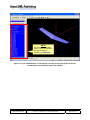
1
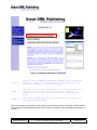
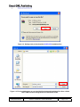
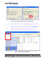
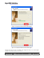
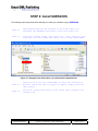
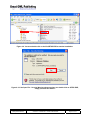
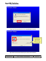
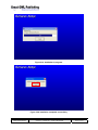
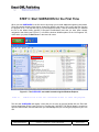
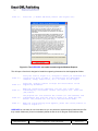
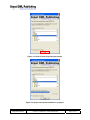
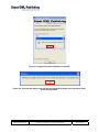
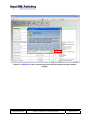
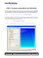
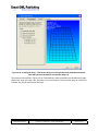
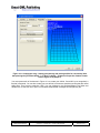
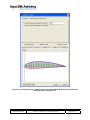
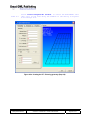
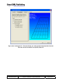
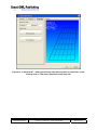
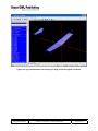
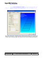
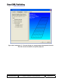
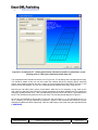
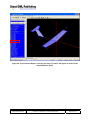
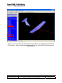
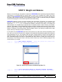
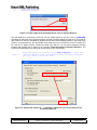
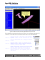
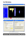
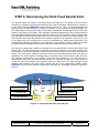
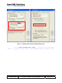
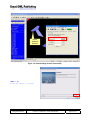
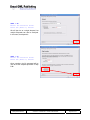
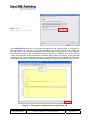
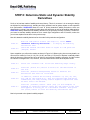
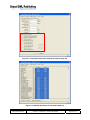
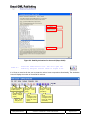
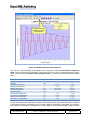
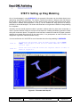
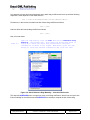
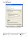
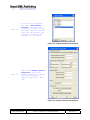
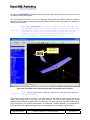
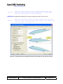
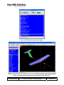
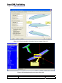
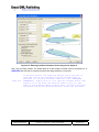
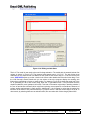
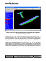
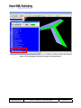
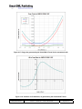
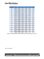
SURFACES
My First Model
A Dedicated Help for the First Time User
August 2009
SURFACES – My First Model
Abbreviations ................................................................................................................ 3 INTRODUCTION ............................................................................................................. 4 STEP 1: Download and Extract SURFACES Installation Files .................................. 5 STEP 2: Install SURFACES ......................................................................................... 11 STEP 3: Start SURFACES for the First Time ............................................................. 15 STEP 4: Creating a Simple Model with SURFACES ................................................. 20 STEP 5: Weight and Balance ...................................................................................... 34 STEP 6: Determining the Stick Fixed Neutral Point ................................................. 41 STEP 7: Trimming the Model for a Level Flight ........................................................ 45 STEP 8: Determine Static and Dynamic Stability Derivatives ................................. 51 STEP 9: Setting up Drag Modeling ............................................................................ 56 Document
Title
Page Numbers
VLMmyfirstmodel.docx
Surfaces – User Manual – Vortex-Lattice Module
Page 2 of 70
Abbreviations
You may encounter the following abbreviations in this text and images. These are their translations.
AOA
AOY
AR
b
EULA
CG
HT
LE
MAC
NACA
S
TR
VT
Angle-Of-Attack
Angle-Of-Yaw
Aspect Ratio
Wing span
End User License Agreement
Center of Gravity
Horizontal Tail
Leading Edge
Mean Aerodynamic Chord
National Advisory Committee for Aeronautics
Wing area
Taper Ratio
Vertical Tail
Math Objects
AOA
AOY
Bht
Bvt
Bw
Href
Pmac
Sht
Svt
Sw
Vcas
Vtas
Vht
Vinf
Vvt
Xcg, Ycg, Zcg
Xneu
Angle-of-Attack
Angle-of-Yaw
HT span
VT span
Wing span
Reference altitude
Percentage of MAC. Variable used for CG location analysis.
HT area
VT area
Wing area
Calibrated airspeed
True airspeed
HT volume
Far-field airspeed
VT volume
VT volume
Stick-fixed neutral point
Document
Title
Page Numbers
VLMmyfirstmodel.docx
Surfaces – User Manual – Vortex-Lattice Module
Page 3 of 70
INTRODUCTION
Thank you for trying out SURFACES.
This document is a dedicated step-by-step instruction manual that helps you to install and explore the
capabilities of SURFACES by building a simple aircraft. The design is a small T-tail straight wing aircraft,
and once complete, you will learn to extract critical information about it, just as you would for your own
design. This document is intended for simplicity of use – in fact you can stop right here and jump into the
first step.
We are certain you will find SURFACES priceless for your aircraft design projects. SURFACES was
developed in a real aircraft design environment and is loaded with highly developed tools that give you
answers quickly and reliably. We consider the program analogous to an extremely sophisticated airplane
calculator. Create a model of your aircraft and then use SURFACES to extract hard-to-get information
about it. Stability derivatives, loads, performance parameters are just the beginning of your discoveries.
You can extract in a matter of seconds some super complicated parameters that would take trained
aerospace engineer weeks to calculate using classical methods. Use the extra time to study variations of
your design to make it even better for its intended mission. Whatever the design task, SURFACES will
save you weeks if not months of work.
SURFACES is the ultimate tool for anyone designing subsonic aircraft, whether it be a professional
aerospace engineer or the designer of homebuilt aircraft. SURFACES is not just user friendly, it provides
you with very powerful features to help design your aircraft.
SURFACES uses a Three-Dimensional Vortex Lattice Method (VLM) to solve the airflow around an
aircraft and extract an incredible amount of information from the solution. Plot the flow solution to better
understand how the flow behaves around the airplane.
SURFACES is the perfect solution in any preliminary design environment, or to reverse engineer existing
airplanes. It allows you to quickly extract loads and stability and control data.
SURFACES allows you to swiftly model any aircraft. Do you have a three-view drawing of your favorite
aircraft? Simply import it in to the environment and scale it up. No pencils, rulers, or calculators are
needed for scaling up the model. You do it all from within SURFACES. It’s as easy as clicking a mouse
button.
SURFACES determines most stability derivatives and, when used with the built-in Aircraft Datasheet
feature, allows you to perform very sophisticated dynamic stability analyses. Import stability derivatives
directly from your Vortex-Lattice analyses into an Aircraft Datasheet and plot the aircraft’s Short Period,
Phugoid, Spiral Stability, Rolling Convergence, and Dutch Roll modes. You can even simulate the
dynamic response of the aircraft in real time!
SURFACES allows you to incorporate all the details of your design, such as airfoil properties, wing twist,
dihedral, multiple lifting surfaces, asymmetric geometries, winglets, deflection of control surfaces and high
lift devices. SURFACES even allows you to account for engine forces as functions of angle-of-attack,
airspeed and altitude, whose properties are taken into account when determining trim or stability
derivatives.
SURFACES allows you to extract surface pressures, forces and moments, force and moment
coefficients, distributed loads, section lift coefficients, and create shear, moment and torsion diagrams on
the model.
Document
Title
Page Numbers
VLMmyfirstmodel.docx
Surfaces – User Manual – Vortex-Lattice Module
Page 4 of 70
STEP 1: Download and Extract SURFACES Installation
Files
The following step-by-step instructions will help you download your evaluation copy of SURFACES and
properly install it.
STEP 1.1
Using an internet browser like Windows Internet Explorer, Safari,
Chrome, Firefox, etc., go to http://www.greatowlpublishing.com/.
You should see something resembling Figure 1-1 in your browser.
STEP 1.2
Press the button titled: [Surfaces] (see the red box in Figure 11).
This will take you to a new webpage dedicated to the Surfaces software. This is shown in Figure 1-2.
Figure 1-1: The homepage of Great OWL Publishing.
Document
Title
Page Numbers
VLMmyfirstmodel.docx
Surfaces – User Manual – Vortex-Lattice Module
Page 5 of 70
Figure 1-2: Webpage dedicated for SURFACES.
STEP 1.3
Press the link “DOWNLOAD EVALUATION PROGRAM!” shown inside the
red box in Figure 1-2. Pressing it will cause the warning in
Figure 1-3 to appear. Go to the next step.
STEP 1.4
Press the [Save] button (see red box in Figure 1-3). This will
open the form in Figure 1-4 and allow you to save the
installation files to a suitable location on your hard disk
drive.
STEP 1.5
When ready to download, press the [Save] button in Figure 1-4.
The download should begin.
The time to download will depend on the speed of your internet connection, but the file is almost 65MB in
size and will take somewhere between 5 and 30 minutes to complete. Once the download completes, go
to Step 1.6.
Document
Title
Page Numbers
VLMmyfirstmodel.docx
Surfaces – User Manual – Vortex-Lattice Module
Page 6 of 70
Figure 1-3: Getting ready to download the SURFACES installation files.
Figure 1-4: Find a suitable place on your hard disk for the zipped installation files. Here a folder
called TEMP has been designated as the destination folder.
Document
Title
Page Numbers
VLMmyfirstmodel.docx
Surfaces – User Manual – Vortex-Lattice Module
Page 7 of 70
Figure 1-5: The same form during and after download completes.
STEP 1.6
Once the download completes a new form appears, similar to the
one in Figure 1-5. Press the [Open] button to extract the files.
STEP 1.7
Pressing the [Open] button in Step 1.6 will probably open a
window similar to the one in Figure 1-6. Go to File->Extract All…
and unzip all the installation files. Figures 1-7 through 1-10
show the Compressed Folders Extraction Wizard. When the
extraction completes, press the [Finish] button as shown in
Figure 1-10.
Figure 1-6: Extracting the installation files.
Document
Title
Page Numbers
VLMmyfirstmodel.docx
Surfaces – User Manual – Vortex-Lattice Module
Page 8 of 70
Figure 1-7: Compressed Folders Extraction Wizard page 1.
Figure 1-8: Compressed Folders Extraction Wizard page 2.
Document
Title
Page Numbers
VLMmyfirstmodel.docx
Surfaces – User Manual – Vortex-Lattice Module
Page 9 of 70
Figure 1-9: Compressed Folders Extraction Wizard page 3.
Figure 1-10: Compressed Folders Extraction Wizard page 4.
Following these steps will leave the installation files unzipped and ready for the actual program
installation. The next step will show you how to do this.
Document
Title
Page Numbers
VLMmyfirstmodel.docx
Surfaces – User Manual – Vortex-Lattice Module
Page 10 of 70
STEP 2: Install SURFACES
The following step-by-step instructions will help you install your evaluation copy of SURFACES.
STEP 2.1
Open Windows Explorer and navigate to the folder where you
extracted the SURFACES installation files (see Figure 2-1).
STEP 2.2
Locate the “Setup” folder (see Figure 2-2). Scroll down the right
hand side file list window and locate a file called “SETUP.EXE”
Figure 2-1: Navigate to the folder where you extracted the installation files.
STEP 2.3
Double-click on the file “SETUP.EXE” to start the installation
process. Should the form in Figure 2-3 appear, simply press the
[Run] button.
STEP 2.4
Follow the instructions shown on the screen and in Figures 2-4a
through 2-4d.
Document
Title
Page Numbers
VLMmyfirstmodel.docx
Surfaces – User Manual – Vortex-Lattice Module
Page 11 of 70
Figure 2-2: You must double-click on the file SETUP.EXE to start the installation.
Figure 2-3: If the Open File – Security Warning shows up when you double-click on SETUP.EXE,
simply press the Run button.
Document
Title
Page Numbers
VLMmyfirstmodel.docx
Surfaces – User Manual – Vortex-Lattice Module
Page 12 of 70
Figure 2-4a: The setup welcome form. Press the [OK] button to proceed.
Press this button only
if you really want to
install in a folder
different from the
default one. This is
not recommended.
Figure 2-4b: Press the button indicated by the red box to start installation.
Document
Title
Page Numbers
VLMmyfirstmodel.docx
Surfaces – User Manual – Vortex-Lattice Module
Page 13 of 70
Figure 2-4c: Installation in progress.
Figure 2-4d: Installation completed successfully.
Document
Title
Page Numbers
VLMmyfirstmodel.docx
Surfaces – User Manual – Vortex-Lattice Module
Page 14 of 70
STEP 3: Start SURFACES for the First Time
When you start SURFACES for the first time it will prompt you to install additional supporting documents.
These documents include tutorial videos, shape files (airfoils), and others. This is only done the first time
the program is run. This step will help you to accomplish this easily. It will be assumed that you installed
the file to the default folder (typically C:\Program Files\Surfaces) and that you have either already
navigated to that folder (see Figure 3-1) or found the shortcut Windows places in the “All Programs” list,
visible when you press the Start button in the lower left corner.
.
Figure 3-1: The SURFACES executable located using the Windows Explorer.
STEP 3.1
Double-click on the file “Surfaces2-8.exe” to start the program.
This will start SURFACES and display a form that you are soon to become familiar with; the End User
License Agreement (EULA) (see Figure 3-2). Pressing the [I ACCEPT THE EULA] button is required to
open the main window, but with that action you acknowledge that you are using the program at your own
risk.
Document
Title
Page Numbers
VLMmyfirstmodel.docx
Surfaces – User Manual – Vortex-Lattice Module
Page 15 of 70
STEP 3.2
Press the [I ACCEPT THE EULA] button (see Figure 3-2).
Figure 3-2: The SURFACES executable located using the Windows Explorer.
This will open a form that is designed to install the supporting documents into their appropriate folders.
STEP 3.3
Using the form in Figure 3-3, navigate to where you extracted the
installation files in STEP 2. You should see the subfolders
(Samples, Setup, Shape Files, etc.) as shown in the figure.
STEP 3.4
Press the [Install] button to begin the installation of the
supporting documents.
STEP 3.5
When the installation completes, you will see a small form
acknowledging a successful install (see Figure 3-5). Press the
[OK] button.
STEP 3.6
The program will now evaluate the license (or lack thereof) and
acknowledges this with the form in Figure 3-6. Press the [OK]
button. The program will now run in the Evaluation Mode.
STEP 3.7
When the Tip-of-the-Day form appears, press the [Close] button as
shown in Figure 3-7.
SURFACES is now ready for use. Note that now you can delete the extracted setup folders and the files
they contain. Make sure you do not mistakenly delete the files in the C:\Program Files\Surfaces folder.
Document
Title
Page Numbers
VLMmyfirstmodel.docx
Surfaces – User Manual – Vortex-Lattice Module
Page 16 of 70
Figure 3-3: Form to install supporting documents.
Figure 3-4: Support document installation in progress.
Document
Title
Page Numbers
VLMmyfirstmodel.docx
Surfaces – User Manual – Vortex-Lattice Module
Page 17 of 70
Figure 3-5: Support document installation completed.
Figure 3-6: This form will appear each time the user starts the program in the evaluation mode.
Press the [OK] button.
Document
Title
Page Numbers
VLMmyfirstmodel.docx
Surfaces – User Manual – Vortex-Lattice Module
Page 18 of 70
Figure 3-7: SURFACES is now up and running. Press the [Close] button to begin using the
program.
Document
Title
Page Numbers
VLMmyfirstmodel.docx
Surfaces – User Manual – Vortex-Lattice Module
Page 19 of 70
STEP 4: Creating a Simple Model with SURFACES
The following model is designed to allow the novice user to quickly become familiar with SURFACES.
Pay close attention to which options and checks are made in each form below before proceeding to the
next step. Additionally, it is assumed you are starting with the program running after completing STEP 3.
STEP 4.1
Start a new project by selecting File->New Project…
This will open a small form on which you need to specify the type of project to create. Press the button
labeled ‘Surfaces Worksheet’ to open a blank worksheet. Maximize the window for added convenience.
Then move on to create surfaces to represent the wing.
STEP 4.2
Select Insert->Trapezoidal Surface…
STEP 4.3
Create the WING using the numbers in the dialog in Figure 4-1a
through 4-1d.
Figure 4-1a: Creating the wing – Entering geometry (Step 4.3).
Document
Title
Page Numbers
VLMmyfirstmodel.docx
Surfaces – User Manual – Vortex-Lattice Module
Page 20 of 70
Figure 4-1b: Creating the wing – This tab will help you create geometrically dependent formulas.
Note the selected checkboxes and options (Step 4.3).
The purpose of the options in Figure 4-1b is to automatically create formulation that calculates wing span,
aspect ratio, wing area, taper ratio, and other for your convenience. There are other ways to create such
formulas, but you will learn these at later time.
Document
Title
Page Numbers
VLMmyfirstmodel.docx
Surfaces – User Manual – Vortex-Lattice Module
Page 21 of 70
Figure 4-1c: Creating the wing – Setting panel density and picking airfoils for root and tip. Note
that pressing the [Pick Root Airfoil…] or [Pick Tip Airfoil…] buttons will open the Camber Creator
form in Figure 4-1d (Step 4.3).
You must press each of the buttons in Figure 4-1c to create your airfoils. If an airfoil is not recognized, a
flat plat is assumed. You can also create your own airfoils, but these are stored as text files that are called
shape files. They have the extension .SHP. You can navigate to the /Surfaces/Shape Files folder and
double-click on one such file to open it in Windows Notepad and investigate how simple they are.
Document
Title
Page Numbers
VLMmyfirstmodel.docx
Surfaces – User Manual – Vortex-Lattice Module
Page 22 of 70
Figure 4-1d: Creating the wing – Picking airfoil. Here select NACA 4416 for the root airfoil and
NACA 4410 for the tip (Step 4.3).
Document
Title
Page Numbers
VLMmyfirstmodel.docx
Surfaces – User Manual – Vortex-Lattice Module
Page 23 of 70
NOTE:
This list contains the Math
Objects, which are algebraic
expressions used for
everything in SURFACES.
Figure 4-2: If you followed Steps 4.1 through 4.3 correctly, the wing will appear as shown,
containing the selected airfoils, twist, and dihedral.
Document
Title
Page Numbers
VLMmyfirstmodel.docx
Surfaces – User Manual – Vortex-Lattice Module
Page 24 of 70
STEP 4.4
Select Insert->Trapezoidal Surface… to create the HORIZONTAL TAIL
(HT). Fill in the form using the numbers in the dialog in Figures
4-3a through 4-3c.
Figure 4-3a: Creating the HT – Entering geometry (Step 4.4).
Document
Title
Page Numbers
VLMmyfirstmodel.docx
Surfaces – User Manual – Vortex-Lattice Module
Page 25 of 70
Figure 4-3b: Creating the HT – This tab will help you create geometrically dependent formulas.
Note the selected checkboxes and options (Step 4.4).
Document
Title
Page Numbers
VLMmyfirstmodel.docx
Surfaces – User Manual – Vortex-Lattice Module
Page 26 of 70
Figure 4-3c: Creating the HT – Setting panel density. Note that no airfoils are picked here, so the
resulting airfoil is a flat plate (symmetrical airfoil) (Step 4.4).
Document
Title
Page Numbers
VLMmyfirstmodel.docx
Surfaces – User Manual – Vortex-Lattice Module
Page 27 of 70
Figure 4-4: If you followed Step 4.4 correctly, the wing and HT will appear as shown.
Document
Title
Page Numbers
VLMmyfirstmodel.docx
Surfaces – User Manual – Vortex-Lattice Module
Page 28 of 70
STEP 4.5
Select Insert->Trapezoidal Surface… one more time and create the
VERTICAL TAIL (VT) by filling the form using the numbers in the
dialog in Figures 4-5a through 4-5c.
Figure 4-5a: Creating the VT – Entering geometry. Note the option selected in the “Create Surface
in Plane” frame is now the X-Z plane, and not the X-Y plane used for the Wing and HT (Step 4.5).
Document
Title
Page Numbers
VLMmyfirstmodel.docx
Surfaces – User Manual – Vortex-Lattice Module
Page 29 of 70
Figure 4-5b: Creating the VT – This tab will help you create geometrically dependent formulas.
Note the selected checkboxes and options (Step 4.5).
Document
Title
Page Numbers
VLMmyfirstmodel.docx
Surfaces – User Manual – Vortex-Lattice Module
Page 30 of 70
Figure 4-5c: Creating the VT – Setting panel density. Note that no airfoils are picked here, so the
resulting airfoil is a flat plate (symmetrical airfoil) (Step 4.5).
Your completed model should look like the one in Figure 4-6; a T-tail design with a straight tapered wing.
You should be aware of that you can also create the surfaces directly by dropping points, stretching
vectors, and inserting surfaces, but this is shown in the accompanying tutorial videos. However, in the
interest of time and simplicity, the user can create trapezoidal surfaces more easily using this tool.
Note that you can hide points, vectors, and surfaces. While this is not necessary, it may clean up the
view. Here let’s hide the points. Do this by clicking somewhere on the black background. This ensures the
workspace (image) has the focus. Then, simultaneously press Shift and P (for Points). This selects all the
points. Then simultaneously press Ctrl and H (for Hide). The resulting image appears in Figure 4-7.
As you can see identified by the red box in Figure 4-6, the wing span (Bw) is 18 ft and wing area (Sw) is
45 ft². Similarly, you can see identified by red boxes in Figure 4-7 the horizontal and vertical tail volumes
should be 0.8496 and 0.0826, respectively. Now let’s add weight to the model using the specialized tools
in SURFACES.
Document
Title
Page Numbers
VLMmyfirstmodel.docx
Surfaces – User Manual – Vortex-Lattice Module
Page 31 of 70
Figure 4-6: If you followed Step 4.5 correctly, the wing, HT, and VT will appear as shown in the
completed basic model.
Document
Title
Page Numbers
VLMmyfirstmodel.docx
Surfaces – User Manual – Vortex-Lattice Module
Page 32 of 70
Figure 4-7: The basic model after the points have been hidden. Also, highlighted are the HT and
VT tail volumes, which are important parameters that one can use to ensure the tail surfaces are
adequately sized.
Document
Title
Page Numbers
VLMmyfirstmodel.docx
Surfaces – User Manual – Vortex-Lattice Module
Page 33 of 70
STEP 5: Weight and Balance
While you can certainly get aerodynamic results from SURFACES without specifying weight and balance
(CG-location), it is recommended you specify these as soon as you complete your model. One of the
reasons is that SURFACES calculates aerodynamic moments about the CG. An incorrectly specified CG
will clearly yield incorrect moments. This is important to keep in mind, in particular when you compare
results from the program to wind tunnel experiments and other testing.
SURFACES features a built-in tool that calculates the total weight, CG-location, and moments and
products of inertia. Setting up this feature is very simple to do. The information, which is stored in math
objects like Wref, Ixx, Iyy, etc., is used when the airplane is trimmed for level flight, or for stability and
control analyses. The simplest way to specify these is to explicitly enter the values, if known, as formulas.
However, the problem in real aircraft design projects is that the moments and products of inertia are far
harder to obtain than the weight. What compounds the problem is that these also change with the CG
location. Choosing to enter these directly would inevitably result in you having to update all the math
objects, which you would soon find too cumbersome.
It is far easier to have SURFACES take care of all of these for you and use the built-in functionality. That
way, when you move the CG around, the program will instantly and automatically update these important
inertia parameters for you. The program uses two types of weight entities to do this; point weights and
distributed weights. Point weights are used to represent components like the engine or fuel tanks, or the
pilot. Distributed weights are used for components that have volume or areas, such as the wing or
horizontal tail. This will become clear in this step, which will show you how to effectively apply the two
weight entities to your model.
STEP 5.1
Select Edit->Select Surfaces... Press the [Select All] button and
then the [OK] button (see Figure 5-1).
Figure 5-1: Selecting all surfaces simultaneously (Step 5-1).
STEP 5.2
Select Tools->Distribute Weight on Selected Surfaces and Nodes...
Enter 400 in the entry box and press the [OK] button (see Figure
5-2).
Document
Title
Page Numbers
VLMmyfirstmodel.docx
Surfaces – User Manual – Vortex-Lattice Module
Page 34 of 70
Figure 5-2: Enter weight of the selected surfaces, here as 400 lbs (Step 5-2).
This will distribute a total weight of 400 lbs onto the model based on the area. That is, SURFACES
calculates the total area of the selected surfaces and then computes weight per total area. The weight of
each surface will then be calculated as (weight per total area of the selected surfaces) x (the area of the
surface). As a consequence, the total weight of the wings turns out to be 293.3 lbs, the HT weighs 58.2
lbs, and the VT weighs 48.5 lbs. Clearly, this adds up to 400 lbs. You can check weight by selecting
surfaces and pressing the F6 button (or by selecting Tools->Properties of Selected Surfaces). The
results will be displayed on the Status bar on the bottom of the main window.
STEP 5.3
Make sure the CG is visible. Select Tools->Options... Check the
‘Show CG, Neutral Point, Aerodynamic Center’ checkbox and press
the [OK] button (see Figure 5-3).
Figure 5-3: Confirm the “Show CG, …” checkbox is marked so you can see the CG in the
workspace (Step 5-3).
Document
Title
Page Numbers
VLMmyfirstmodel.docx
Surfaces – User Manual – Vortex-Lattice Module
Page 35 of 70
The CG is too far aft.
One would expect it to
be closer to the wing’s
quarter-chord.
Figure 5-4: We can see the CG location (black-white circle) is too far aft.
When completed, your model should look like the one in Figure 5-4. It is immediately evident that the CG
is too far aft. To fix this and to allow us to control the location of the CG, let’s create a ballast point.
STEP 5.4
Press the X-Y tab on the bottom of the workspace.
This will display the model projected onto the XY plane.
STEP 5.5
Press the sketch-mode icon to display the sketch
toolbar.
STEP 5.6
Press the Insert a point icon and drop a point
somewhere in front of the wing, near the X-axis,
similar to what is shown in Figure 5-5. Rightclick to go back to neutral mode.
STEP 5.7
Select the point by clicking on it and press the
Insert a node point icon to convert it to a node.
This will open a dialog box to allow user to
enter additional data. Enter the information
shown in Figure 5-6. Once completed, press the
[OK] button.
Document
Title
Page Numbers
VLMmyfirstmodel.docx
Surfaces – User Manual – Vortex-Lattice Module
Page 36 of 70
This point will
be converted to
a Node.
Figure 5-5: Drop the point (to be converted to a node) in a location similar as shown (Step 5.6).
Figure 5-6: Information entered with Step 5.7.
Document
Title
Page Numbers
VLMmyfirstmodel.docx
Surfaces – User Manual – Vortex-Lattice Module
Page 37 of 70
Return to the 3-D view by pressing the X-Y-Z tab (see the bottom of Figure 5-5). When completed your
model should look like the one in Figure 5-7. To see what the true location of the CG is at this point,
locate the math objects Pmac and Xcg in the object list on the left hand side (Pmac is highlighted in
Figure 5-7). The variable Pmac stores the CG location as a percentage of the Mean Aerodynamic Chord
(Cref, found under the REFERENCE PARAMETERS block in the Math Object list). We see the CG is
located at 13.967% MAC or 0.47 ft. Often it is necessary to specify directly the location of the CG.
SURFACES features a tool to help you accomplish that. The following steps show how to move the CG to
25% MAC.
Wref variable
Select this node
with Step 5.8.
Pmac variable
Figure 5-7: The model with ballast point defined.
STEP 5.8
Click once on the Ballast node you created to select it (see
Figure 5-7). We will move it using a special tool. Note that
SURFACES will only move the selected node (or nodes), when
adjusting the CG location. If none are selected a warning message
appears.
STEP 5.9
Select Tools->Specify a CG Location… Select the option “Xcg in
terms of %MAC, Pmac” and enter the value shown in Figure 5-8.
STEP 5.10
Press the [Adjust] button. Respond to the warning that appears by
pressing [Yes]. Then, press [Close] button to exit the form.
Document
Title
Page Numbers
VLMmyfirstmodel.docx
Surfaces – User Manual – Vortex-Lattice Module
Page 38 of 70
When completed, your node will be closer to the wing than before, or but SURFACES has automatically
changed its X location from -4 to -3.347556 ft, moving the CG in the process (i.e. to the 25% MAC). Now
let’s ensure SURFACES calculates the moments and products of inertia.
Figure 5-8: Specifying a CG location (Step 14).
STEP 5.11
Select Edit->Establish Geometric Relationships… This opens the
form in Figure 5-9. Select the tab labeled ‘Inertia’.
STEP 5.12
Press the [Compute Wref, Ixx,…,Iyz using Model Weight] button.
When the geometric-inertia relationships have been created the
form of Figure 5-10 appears. Press the [OK] button. Press the
[Close] button on the original form to close it.
SURFACES will now calculate the moments and products of inertia based on the point weight and
distributed weight you have entered. If you inspect the math objects used for inertia you’ll see they have
the following formulas.
Variable
Wref
Ixx
Iyy
Izz
Ixy
Ixz
Iyz
Formula
[Wref]
[Ixx]
[Iyy]
[Izz]
[Ixy]
[Ixz]
[Iyz]
Remark
Reference weight.
Moment of inertia about the x-axis.
Moment of inertia about the y-axis.
Moment of inertia about the z-axis.
Product of inertia in the xy-plane.
Product of inertia in the xz-plane.
Product of inertia in the yz-plane.
When SURFACES evaluates the math objects, it will look for bracketed functions. When it finds functions
like Wref, it will assign the weight it computes anyway to that object.
Document
Title
Page Numbers
VLMmyfirstmodel.docx
Surfaces – User Manual – Vortex-Lattice Module
Page 39 of 70
Figure 5-9: Press the button to establish inertia-geometry relations.
Figure 5-10: Inertia-geometry relations have been established.
Document
Title
Page Numbers
VLMmyfirstmodel.docx
Surfaces – User Manual – Vortex-Lattice Module
Page 40 of 70
STEP 6: Determining the Stick Fixed Neutral Point
This step will answer the question: “How far aft can the CG safely go?” The answer is crucial to a safe
operation of our airplane and will set the farthest aft limit of the CG envelope. Unfortunately, the answer to
it is not simple, although SURFACES can help determine this for you. Figure 6-1 shows parameters that
typically go into the determination of a viable CG envelope. If you are a serious airplane designer it is
your responsibility to ensure that a viable CG envelope be established. This will simply result in a far safer
airplane. In the opinion of this editor, some designers of homebuilt airplanes have done a really bad job at
this and designed airplanes which operate with the CG far too aft. This manifests itself in airplanes with
very light stick forces and requires piloting more like what one would expect from unstable aircraft. This
may have been done under the pretense that it makes the airplane more “responsive” and “fun to fly”, but
it is far likelier this is the consequence of a lack of understanding of stability and control theory. The
corresponding airplanes are dangerous. The customers of such airplanes are often unaware of the risks
involved in flying such airplanes and sometimes pay dearly. Make sure you don’t fall into this trap.
The first step in determining a viable CG envelope lies in the determination of the so-called Stick-Fixed
Neutral Point. The name comes from the fact that it assumes the elevator is immovable, typically in the
neutral-position. This point is generally a good indicator of how far aft the CG can go, but is not the final
answer. Two other points, called the Stick-Free Neutral Point and Maneuvering Point, must also be
determined. The former requires knowledge about the elevator hinge moment and the latter about the
pitch damping characteristics of our airplane. Each adds more challenge to our work and will be
considered at a later time. The forward points will also be considered at a later time. These points fall
around the viable CG envelope and eventually dictate the usable limit. The viable envelope should
generally offer between 3-5% MAC buffer, forward and aft of the corresponding stability points.
SURFACES can be used to determine these points, although your knowledge is required to guide the
process.
Balked landing limit
T-O rotation limit
Elevator stall limit
Stick-Fixed neutral point
Viable
CG
Limit
3-5%
Buffer
Maneuvering point
3-5%
Buffer
Stick-Free neutral point
Figure 6-1: Factors that affect the viable CG limit.
Document
Title
Page Numbers
VLMmyfirstmodel.docx
Surfaces – User Manual – Vortex-Lattice Module
Page 41 of 70
Anyway, let’s determine the Stick-Fixed Neutral Point per the following steps.
STEP 6.1
Press the VLM Console icon. This will open the
Vortex-Lattice Method Console (VLM Console) shown
in Figure 6-2.
Figure 6-2: The VLM Console (Step 6.1).
Note that when you create a new project, SURFACES has preset values for a multitude of variables.
Among those are the airspeed variables (Vcas, Vtas, Vinf), altitude (Href), and angle-of-attack (AOA).
Naturally, you can change these with ease, but currently Vcas=100 knots, Href=0 ft, and AOA=2°. In
interest of saving time for this demo, let’s assume these will suffice for our analysis.
STEP 6.2
Select Tasks->Determine Neutral Point… Press the [Analyze] button
to begin, and after a few seconds, once done, review the results
in Figure 6-3.
Document
Title
Page Numbers
VLMmyfirstmodel.docx
Surfaces – User Manual – Vortex-Lattice Module
Page 42 of 70
Figure 6-3: Determining neutral point (Step 6.2).
The complete report is displayed below. SURFACES uses two methods to compute the neutral point.
Generally you should pick the neutral point with the lower value of Xneu, here this implies Method 2. Let’s
transfer the resulting value to the variable Xneu in the model, which currently has the initial value 0.
==========================================================================================
NEUTRAL POINT ANALYSIS
==========================================================================================
Filename ........ : SimplePlane(03162009).SRF
Date ............ : 03-16-2009
Time ............ : 21:17:00
ANALYSIS VALUES:
----------------------------------------------------ID
XCG
AOA
CL
CMY
----------------------------------------------------1
7.5032e-01
2.0000° 3.8059e-01 -1.1761e-01
2
1.7503e+00
2.0000° 3.8059e-01 3.2670e-02
3
7.5032e-01
3.0000° 4.6946e-01 -1.5413e-01
4
1.7503e+00
3.0000° 4.6946e-01 3.1248e-02
--------------------------------------------------------------------------------------------------------METHOD 1
----------------------------------------------------Calculates Xneu from the expression:
Xneu = Xcg - Cref·dCm/dCL
= 0.75032 - (2.534505)·(-0.036512)/(0.088875)
= 1.791557 (66.08247% MAC)
----------------------------------------------------METHOD 2
----------------------------------------------------Calculates Xneu by evaluating changes of CG and AOA on Cm:
Function 1 (degrees): -0.036512·AOA - 0.044590
Document
Title
Page Numbers
VLMmyfirstmodel.docx
Surfaces – User Manual – Vortex-Lattice Module
Page 43 of 70
Function 1 (radians): -2.091979·AOA - 0.044590
Function 2 (degrees): -0.001422·AOA - 0.154126
Function 2 (radians): -0.081474·AOA - 0.154126
Xneu = 1.790844 (66.05433% MAC)
Total time:0h:00m:05s
STEP 6.3
Press the [Transfer] button and select the option ‘Neutral point
using Method 2’. This displays a notification. Press the [OK]
button to close it. Press the [Close] button on the form to close
it as well.
Note the [Copy Report] button in the form in Figure 6-3. It allows you to copy the entire text in the form to
the clipboard. It is a good practice to copy and paste it as a comment under Edit->Remark… in the main
worksheet for future reference.
This result says that the airplane becomes statically unstable about the longitudinal axis (with the elevator
fixed) if the CG is moved farther aft than 66% MAC. As a rule of thumb, one can expect the Stick-Free
Neutral Point to be approximately 5-8% MAC ahead of the Stick-Fixed point. Here, until we know better,
let’s pick 8%. If we further consider the application of a 5% buffer for the aft limit, a preliminary location of
the aft CG limit can be set at 66 – 8 – 5 = 53% MAC. Now, the reader must keep in mind that this does
not include the effect of a fuselage, which destabilizes the airplane and moves the neutral points farther
forward.
Document
Title
Page Numbers
VLMmyfirstmodel.docx
Surfaces – User Manual – Vortex-Lattice Module
Page 44 of 70
STEP 7: Trimming the Model for a Level Flight
In stability and control theory, a trimmed airplane means that the controls are deflected for a stable level
flight. For the pilot this usually means that the stick-force required for a level flight at a given airspeed is
zero. Trimming can be accomplished by a number of means. Reversible control systems usually use trim
tabs to help deflect a control surface (which the pilot adjusts until stick forces are zero). Irreversible ones,
such as hydraulic control systems, may simply use brute force.
The importance of trimming cannot be over-emphasized. The characteristics of a trimmed airplane are
denoted by its airspeed, AOA, and elevator deflection. The user must recognize that trimming the airplane
not only requires the elevator to be deflected, but that the action of deflecting the elevator will effectively
result in a geometry that is different from the original one. Consequently, trimming the airplane requires a
different mathematical solution than the original one. A trimmed airplane is, from a certain point of view, a
“version” of the original aircraft that results in the desired lift and a zero pitching moment at a given
airspeed. SURFACES will automatically trim the airplane for you by deflecting the elevator as it seeks this
equilibrium condition. You will learn how to do this correctly in this step, and we will trim the airplane to
carry 700 lbf at 100 KCAS. First, however, we must tell the program which surfaces serve as the
elevators. Start by returning back to the worksheet where the model is.
STEP 7.1
Double-click on one of the two surfaces that serve as the
horizontal tail. This opens the dialog box shown in Figure 7-1.
Select the ‘Edge Deflections’ tab. Set number of chord wise
panels on the aft edge to deflect to 2.
STEP 7.2
In the same dialog select the ‘Reference’ tab. Check the ‘Surface
is used for Pitch Control’. Press the [OK] button. If a warning
appears stating there’s already a VLM solution in memory, just
press the [Yes] button.
STEP 7.3
Repeat Steps 7.1 and 7.2 for the other horizontal surface. Then
move to Step 7.4.
Also, by now, it would be a good idea to save the work. Here, we select File->Save As… and call it
SIMPLE DEMO.SRF. You should do the same.
You have now given SURFACES information it can use to automatically deflect the elevators to trim the
model for level flight. You can try the functionality out by displaying the VLM Console and select the
‘Controllers’ tab. For instance, enter -20 in the Pitch control textbox and press the [Set] button to see the
model regenerate with that deflection, as shown in Figure 7-2. Once done, press the [Reset] button to
return the elevators to a neutral deflection (0°) and get ready to trim the model.
Document
Title
Page Numbers
VLMmyfirstmodel.docx
Surfaces – User Manual – Vortex-Lattice Module
Page 45 of 70
Figure 7-1: Setting up elevator functionality (Steps 19-21).
STEP 7.4
Select Tasks->Trimmed Level Flight... to display the Trim wizard.
Follow the steps shown in the subsequent steps of images in Step
7.5.
Document
Title
Page Numbers
VLMmyfirstmodel.docx
Surfaces – User Manual – Vortex-Lattice Module
Page 46 of 70
Notice
deflected
elevators
Figure 7-2: Demonstrating elevator functionality.
STEP 7.5a:
Press the [Next >>] button.
Document
Title
Page Numbers
VLMmyfirstmodel.docx
Surfaces – User Manual – Vortex-Lattice Module
Page 47 of 70
STEP 7.5b:
Ensure the selection shown.
Press the [Next >>] button.
We will just trim to a single airspeed, but
multiple airspeeds can also be analyzed.
In this case, the airspeed is
STEP 7.5c:
Ensure the selection shown.
Press the [Next >>] button.
Once complete, the lift generated will be
700 lbs at the airspeed specified in Step
7.5b.
Document
Title
Page Numbers
VLMmyfirstmodel.docx
Surfaces – User Manual – Vortex-Lattice Module
Page 48 of 70
STEP 7.5d:
Ensure the selection shown.
Press the [Next >>] button.
Here we allow 30 iterations before a
solution will be declared as unachievable.
If solution is found, the resulting lift will be
700 ±1 lbf and the moment 0 ±1 ft·lbf. As a
rule of thumb, acceptable accuracy is
provided by specifying 1% of the weight.
Here, the accuracy is closer to 0.14%.
STEP 7.5e:
Ensure the selection shown.
Press the [Next >>] button.
Note that solution files can be created and
saved using the file name entered as a
seed.
Document
Title
Page Numbers
VLMmyfirstmodel.docx
Surfaces – User Manual – Vortex-Lattice Module
Page 49 of 70
STEP 7.5f:
Press the [Trim!] button.
Once SURFACES begins to trim, you can follow the progress on the ‘Progress Table’ or ‘Progress Plot’
tabs (see Figure 7-3). The time to trim largely depends on the number of panels in the model and
accuracy desired. The model presented here took 16 iterations and 31 seconds to trim. Press ‘Summary’
tab to read the results for each completed trim speed. In this case, the model will fly level at an AOA of
3.3449° and will require an elevator deflection of -4.3966° (trailing edge up) to balance. The lift generated
is 699.587 lbf (OK, 700 lbf) and moment about the y-axis (located at the CG) is 0.287698 ft·lbf. The model
is automatically set to the resulting AOA and elevator deflection. Press the [Close] button to exit the form.
Figure 7-3: Trim progress is displayed on the ‘Progress Plot’ tab.
Document
Title
Page Numbers
VLMmyfirstmodel.docx
Surfaces – User Manual – Vortex-Lattice Module
Page 50 of 70
STEP 8: Determine Static and Dynamic Stability
Derivatives
So far, a lot has been made of stability and control theory. This is for a reason. It is not enough to design
an airplane for performance only; handling and flying qualities have far greater impact on safe operation
than performance. SURFACES allows the user to quickly determine stability derivatives, which are
determined to evaluate if the airplane is stable about the three axes as well as its handling characteristics.
SURFACES always determines the stability derivatives of the geometry currently in memory. Therefore, if
you intend to evaluate stability derivatives for a certain flight configuration and CG location, make sure
you trim the airplane first as done in the previous step.
Next let’s determine stability derivatives for the model in this particular configuration.
STEP 8.1
With the VLM Console visible (see Step 6.1) select Tasks>Determine Stability Derivatives... to display the Stability
Derivatives form.
STEP 8.2
Check and uncheck the boxes shown in Figure 8-1 and press the
[Analyze] button.
Upon completion you will see the results as shown in Figure 8-2. Without going into too many details, we
can see from values for Cma (-2.119), Clb (-0.105), and Cnb (0.172) that our airplane is statically stable
about all three axes. What we don’t know at this time are its dynamic stability properties. And this is what
we intend to investigate next. First, however, we must transfer these results to the airplane model.
STEP 8.3
Select the ‘Transfer’ tab. Follow the remaining steps closely.
STEP 8.4
Press the [Select All] button to select all the derivatives in
the list.
STEP 8.5
Press the [Deselect Nonrequested] button to deselect the
derivatives that were not calculated.
STEP 8.6
In addition, uncheck the following variables: CL, CDi, CD, CDa,
hcg, and hn (see Figure 8-3). This will prevent them from being
overwritten, but they already contain algebraic expressions that
we don’t want to be deleted.
STEP 8.7
Press the [Transfer] button. Press [Yes] (in this example) if
prompted to overwrite formulas. Press the [OK] button on the form
that appears to notify you of a successful transfer. Then press
the [Close] button to close the Stability Derivatives form.
Now let’s proceed to the dynamic stability analysis.
Document
Title
Page Numbers
VLMmyfirstmodel.docx
Surfaces – User Manual – Vortex-Lattice Module
Page 51 of 70
Figure 8-1: Preparing to determine stability derivatives (Step 23).
Figure 8-2: Stability derivatives for the model (Step 23).
Document
Title
Page Numbers
VLMmyfirstmodel.docx
Surfaces – User Manual – Vortex-Lattice Module
Page 52 of 70
Figure 8-3: Stability derivatives for the model (Steps 24-28).
STEP 8.7
Press the STAB Console icon. This will open the
Stability Analysis Console shown in Figure 4-29.
It is left as an exercise for the user to press the various icons to experience functionality. The simulation
icons will display the motion of the aircraft in real time.
Longitudinal stability
analysis (report)
Lateral/directional
stability analysis
(report)
Root
locus
analysis tool
Short period and
Phugoid
mode
(plots)
Spiral
convergence, Roll
convergence, and
Dutch roll modes
(plots)
Short period and
Phugoid
mode
(simulation)
Spiral
convergence, Roll
convergence, and
Dutch roll modes
(simulation)
Document
Title
Page Numbers
VLMmyfirstmodel.docx
Surfaces – User Manual – Vortex-Lattice Module
Page 53 of 70
Press this icon to
display the Dutch
roll response.
Figure 8-4: Stability analysis module (Step 29.
You can get a report detailing the properties of the response by selecting View->Show Comparison
Table. The resulting table is shown below. This is but one of many ways to extract information from the
STAB module. Also try Analysis->Create Analysis Report… to get a more detailed dynamic stability
report.
Description
Airspeed
Altitude
Period of oscillation
Damping coefficient
Natural frequency
Damped frequency
Damping Ratio
Time to 0.5 Amplitude
Cycles to 0.5 Amplitude
Time to 0.1 Amplitude
Cycles to 0.1 Amplitude
Symbol
Vtas
Href
T
n
Wn
Wd
Zeta
t½
N½
t0.1
N0.1
Unit
KTAS
ft
sec/cycle
1/sec
cycles/sec
cycles/sec
sec
cycles
sec
cycles
SIMPLE DEMO.SRF
100
0
2.450
-0.0612
2.5648
2.5641
0.0238
11.3324
4.6246
37.6454
15.3626
Among interesting results is that while the Dutch roll damping is stable (Zeta is 0.0238) and the oscillation
is convergent, however, this damping is so low that it would be considered unacceptable if this airplane
was intended for occupants. Documents such as MIL-HDBK-1797 recommend damping ratios in excess
Document
Title
Page Numbers
VLMmyfirstmodel.docx
Surfaces – User Manual – Vortex-Lattice Module
Page 54 of 70
of 0.10. Federal Aviation Regulations 23.181 requires the airplane’s amplitude to dampen to 1/10th of the
initial amplitude in no more than 7 cycles. This airplane requires over 15 cycles. We clearly have
additional work to do on this plane in order to improve the Dutch roll damping. But for now, let’s save the
work done so far.
STEP 8.9
Press the Save icon.
Document
Title
Page Numbers
VLMmyfirstmodel.docx
Surfaces – User Manual – Vortex-Lattice Module
Page 55 of 70
STEP 9: Setting up Drag Modeling
One of the advantages in using SURFACES is the geometric information can be utilized directly when
determining aerodynamic parameters. For instance, consider the balance a designer must find between
lift and drag. A large wing area results in a lower stalling speed, but greater drag and structural weight.
Being able to evaluate such parameters on the fly, as one modifies the wing (and thus its area) is
priceless to the aircraft designer. This section will show how to use geometric relations in drag modeling
for our airplane.
Generally, the user should prepare models for geometric relations after they have been constructed, in
order to prevent relations to become corrupt as a consequence of adding and deleting geometric entities
during the construction phase. This particular model has been created such that all the proper geometric
relations were created along the way. By the same token, it is a good practice to check for errors in the
assignment of geometric references before solving.
You can read Section 9 in VLM.PDF for more information about the drag modeling in SURFACES.
STEP 9.1
If starting the program, open the demo airplane. Select File>Open… and navigate to find the file SIMPLE DEMO.SRF. Doubleclick to open.
STEP 9.2
Select the X-Y-Z view and orient the airplane similar to what is
shown in Figure 9-1.
Figure 9-1: The model after Step 9.2.
Document
Title
Page Numbers
VLMmyfirstmodel.docx
Surfaces – User Manual – Vortex-Lattice Module
Page 56 of 70
Let’s assume we have done some homework on the basic drag coefficient and come up with the following
expression, which depends on both AOA and AOY:
CDo = 0.001+0.05*(AOA*Pi/180)^2+0.02*(AOY*Pi/180)^2
Furthermore, in this context, let’s define the skin friction drag coefficient as follows:
CDf = [CDf]
And let’s define the induced drag coefficient as follows:
CDi = [CDi]
Now, let’s enter these:
STEP 9.3
Open the VLM Console. From the Edit menu select Reference Drag
Modeling… (See Figure 9-2). This opens the dialog box shown in
Figure 9-3. Enter the above drag coefficients and other
information as shown in the figure. When done, press the [OK]
button to store the entered information and close the form.
Figure 9-2: Select Reference Drag Modeling… from the VLM Console.
This step tells SURFACES how to compute our three crucial drag coefficients. We will now set up the skin
friction modeling for the surfaces and tell SURFACES how exactly to compute the skin friction drag.
Document
Title
Page Numbers
VLMmyfirstmodel.docx
Surfaces – User Manual – Vortex-Lattice Module
Page 57 of 70
Figure 9-3: Step 9.3 calls for this form to be filled out as shown.
Document
Title
Page Numbers
VLMmyfirstmodel.docx
Surfaces – User Manual – Vortex-Lattice Module
Page 58 of 70
STEP 9.4
Go back to the worksheet
and select Edit->Select
Surfaces… The press the
[Select All] button in the
form that opens up and then
press the [OK] button (see
Figure 9-4). Now all the
surfaces are selected.
Figure 9-4: A quick selection of all surfaces.
STEP 9.5
Then select Modify->Surface
Properties… Select the
option ‘Use Curve A1 and A2
skin friction drag’ as
shown in Figure 9-5. Press
[OK].
Figure 9-5: A quick selection of all surfaces.
Document
Title
Page Numbers
VLMmyfirstmodel.docx
Surfaces – User Manual – Vortex-Lattice Module
Page 59 of 70
This step tells SURFACES to calculate the skin friction drag using information we have yet to enter for the
A1 and A2 curves of the surfaces.
First, let’s assume the HT and VT are to be designed using laminar flow airfoils capable of sustaining
50% laminar flow. Let’s also assume the wing will sustain laminar flow as discussed in the example of
Section 9.3 of VLM.PDF.
STEP 9.6
Select all the vectors as shown in Figure 9-6. Make sure you use
the rubberband when selecting the centerline vectors as there are
really three vectors (or airfoils) there; two belonging to the HT
root and one to the VT tip. The following assumes you did this
correctly. Note that if the vectors do not highlight, press
Ctrl+Q do display all objects and then try again.
There are 3
vectors here!
Figure 9-6: A1 and A2 curves have been selected for all surfaces to be included.
STEP 9.7
Select Tools->Distribute Laminar Transition for Selected Vectors…
from the worksheet.
This opens the form shown in Figure 9-7. As said earlier, we are assuming here that the airfoils can
sustain 50% laminar flow on the upper and lower surfaces. This case is often checked by aircraft
designers and is especially prepared here for quick entry. You can simply press the buttons labeled [0%],
[25%], and [50%] to set up these special cases. This assumes a constant transition (i.e. independent of
AOA) throughout the operational range, which is not necessarily true, but handy for quick-studies.
Document
Title
Page Numbers
VLMmyfirstmodel.docx
Surfaces – User Manual – Vortex-Lattice Module
Page 60 of 70
STEP 9.8
Press the [50%] button to fill in the textboxes in the form.
Select the option ‘Smooth molded composite’ for surface type.
Press the [OK] button to accept the editing.
SURFACES is equipped with a handy tool to help you visualize your work. Let’s turn it on.
STEP 9.9
Open the VLM Console. Select the ‘Panel Results’ tab find and
check the option ‘Upper surface laminar region’ (see Figure 9-8).
View the results in Figure 9-9).
Figure 9-7: Entering laminar-to-turbulent transition information for the selected vectors.
Document
Title
Page Numbers
VLMmyfirstmodel.docx
Surfaces – User Manual – Vortex-Lattice Module
Page 61 of 70
Figure 9-8: Display laminar-turbulent regions.
Figure 9-9: Image shows the laminar flow region (green) on the HT and VT.
Document
Title
Page Numbers
VLMmyfirstmodel.docx
Surfaces – User Manual – Vortex-Lattice Module
Page 62 of 70
Note that at computation time, SURFACES will compare the aircraft AOA to the ones filled in Figure 9-7
and estimate the transition locations at that angle-of-attack. If the AOA is less than the value AOA1 then
the transition values entered for the low angle-of-attack condition will be used. If the AOA is larger than
AOA2 then the values entered for the high angle-of-attack condition will be used. With that in mind, let’s
set up the mixed boundary-layer conditions on the wing.
STEP 9.10
Select the wing tip vectors as shown in Figure 9-10.
STEP 9.11
Select Tools->Distribute Laminar Transition for Selected Vectors…
from the worksheet. Enter the information shown in Figure 9-11.
STEP 9.12
Select the wing root vectors as shown in Figure 9-12. Again, make
sure you use the rubberband when selecting the centerline vectors
as there are two vectors there. The following assumes you did
this correctly.
STEP 9.13
Select Tools->Distribute Laminar Transition for Selected Vectors…
from the worksheet. Enter the information shown in Figure 9-13.
Figure 9-10: Selecting the wing tip vector in Step 9.10.
Document
Title
Page Numbers
VLMmyfirstmodel.docx
Surfaces – User Manual – Vortex-Lattice Module
Page 63 of 70
Figure 9-11: Entering transition information for the wing tip in Step 9.11.
There are 2
vectors here!
Figure 9-12: Selecting the wing root vector in Step 9.12.
Document
Title
Page Numbers
VLMmyfirstmodel.docx
Surfaces – User Manual – Vortex-Lattice Module
Page 64 of 70
Figure 9-13: Entering transition information for the wing root in Step 9.13.
Now, only one thing remains. The wetted area for all the surfaces involved must be accounted for, or
SURFACES won’t be able to compute the skin friction drag coefficient. Let’s do this.
STEP 9.14
In the math objects list under the Objects tab on the pane in
left hand side of the worksheet, find the variable Swet. It
should be in a block of variables under the title “REFERENCE
PARAMETERS”. Double-click on it to open the variable editor (see
Figure 9.10-1) and enter the function [Swet(1,2,3,4,5)] (the
order of the arguments doesn’t matter here). This will calculate
the wetted area of the selected surfaces. Press [OK] when done.
Document
Title
Page Numbers
VLMmyfirstmodel.docx
Surfaces – User Manual – Vortex-Lattice Module
Page 65 of 70
Figure 9-14: Editing variable Swet.
That’s it. The model is now ready to be used for drag estimation. The model with the entered laminar flow
regions is shown in Figure 9-15. The reported total wetted area is 123.73 ft². The skin friction drag
coefficient for the entire aircraft is 0.00829, but this yields a skin friction drag of a 12.65 lbf. But there is
more. SURFACES allows us to take a closer look at some other details about the skin friction drag. From
the VLM Console’s Panel Results tab you can select to have the program display the resulting skin
friction drag coefficients or forces on each surface. For instance, Figure 9-16 shows that each half of the
HT is generating 0.9 lbf of skin friction drag, while the VT generates some 1.3 lbf (remember that the
airplane modeled is small, perhaps UAV sized). This kind of information might help in deciding whether if
the use of laminar-flow surfaces (which might end up being more expensive to manufacture because of
surface quality requirements) is really worth it. Additionally, it is of interest in noting that by setting the
transition of all airfoils to 0% (turbulent airfoils) CDf jumps to 0.01077 and skin friction drag to 16.42 lbf. In
other words, by selecting laminar over turbulent airfoil, we can reduce skin friction drag by about 30%!
Document
Title
Page Numbers
VLMmyfirstmodel.docx
Surfaces – User Manual – Vortex-Lattice Module
Page 66 of 70
Figure 9-15: The model displaying the extent of laminar flow regions after Step 9.15 has been
completed (green panels). Note the magnitude of the CDf for the entire aircraft is 0.00628. This
generates a skin friction drag of 9.57 lbf.
Furthermore, now that we have created a drag model for the airplane, we can learn a number of
performance related things about it. This is done by creating the drag polar for the full airplane using the
Virtual Wind Tunnel, which can be found on the VLM Console. The VWT creates a table for a sweep (for
instance an “alpha”-sweep is when you change only the angle-of-attack) containing 159 parameters.
Among those are the drag coefficients. The results from this effort are shown in Figures 9-17 through 919. Note that elevator deflection was set to 0° prior to running the wind tunnel.
Another important performance parameter is the L/D curve in Figure 9-18. From it we learn that the
expected maximum L/D is 35.34 at an AOA of 3°. While an impressive glide ratio, we know to take it with
a grain of salt as it does not include contributions from a fuselage or landing gear and so on. Also, this
simplified example assumes the amount of laminar flow stays constant with AOA, which is unlikely, and
the basic drag coefficient is probably too low as well, especially at higher AOAs. At any rate, we have now
a reasonable first stab at the drag properties of our airplane. The procedure for your original aircraft will
be similar to the one shown here.
Document
Title
Page Numbers
VLMmyfirstmodel.docx
Surfaces – User Manual – Vortex-Lattice Module
Page 67 of 70
Figure 9-16: Displaying the skin friction drag on component basis.
Document
Title
Page Numbers
VLMmyfirstmodel.docx
Surfaces – User Manual – Vortex-Lattice Module
Page 68 of 70
Figure 9-17: Drag polar generated by the Virtual Wind Tunnel for the example aircraft.
Figure 9-18: Variation of L/D with AOA, as generated by the Virtual Wind Tunnel.
Document
Title
Page Numbers
VLMmyfirstmodel.docx
Surfaces – User Manual – Vortex-Lattice Module
Page 69 of 70
Figure 9-19: Data generated by the Virtual Wind Tunnel used for Figures 9-17 and 9-18.
END OF DOCUMENT.
Document
Title
Page Numbers
VLMmyfirstmodel.docx
Surfaces – User Manual – Vortex-Lattice Module
Page 70 of 70