1
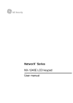
GE
Security
NetworX Series
TM
NX-1750 ProxPad
Installation manual
g
imagination at work
Symbol Legend
Indicates a procedure, practice, condition, or statement that, if not strictly
observed, could result in personal injury.
* This symbol indicates electrical warnings and cautions.
Warning
Indicates a procedure, practice, condition, or statement that, if not strictly
observed, could result in damage to or destruction of equipment or property.
** This symbol indicates general warnings and cautions.
Caution
Indicates an essential or important procedure, instruction, condition, or
statement.
Note
Tip
&
Indicates a user tip. Provides helpful information that is not normally defined in
regular use, but from an experienced user.
Indicates a key or button should be pressed to enter data.
Enter
NX-1750 Installation manual
Page 2
18/02/05
CONTENTS
CONTENTS ............................................................................................................................................................................3
GENERAL DESCRIPTION.......................................................................................................................................................4
ORDERING INFORMATION ..................................................................................................................................................4
INSTALLATION AND WIRING...............................................................................................................................................5
ENROLLING...........................................................................................................................................................................5
ADDRESSING ........................................................................................................................................................................6
LED DESCRIPTIONS ..............................................................................................................................................................7
PROGRAMMING....................................................................................................................................................................8
USING THE LED KEYPAD....................................................................................................................................................8
Entering the Program Mode............................................................................................................................................................. 8
Entering the Module Address ........................................................................................................................................................... 8
Programming a Location ................................................................................................................................................................. 8
Exiting the Program Mode:............................................................................................................................................................... 9
USING THE LCD KEYPAD .................................................................................................................................................10
PROGRAMMING DATA TYPES ..........................................................................................................................................10
USER CARDS .......................................................................................................................................................................10
Adding One User ............................................................................................................................................................................ 11
Adding Multiple Users with Auto-Increment.................................................................................................................................. 11
Activate One User (Single User) ...................................................................................................................................................... 12
De-Activate One User ..................................................................................................................................................................... 12
Delete / Reset One User.................................................................................................................................................................. 12
PROGRAMMING LOCATIONS.............................................................................................................................................13
Location 0
Programming the Scan Functions ....................................................................................................................... 13
Location 1
Programming the X-10 Address for the Scan Functions .................................................................................... 13
Location 2
Programming the Reader option........................................................................................................................ 14
Location 3
Programming the Zones ..................................................................................................................................... 16
Location 4
Programming the Various Reader Timers .......................................................................................................... 16
Location 5
Programming the Opening Time for Schedule 1 ................................................................................................ 16
Location 6
Programming the Closing Time for Schedule 1 .................................................................................................. 17
Location 7
Programming the Days for Schedule 1 .............................................................................................................. 17
Locations 8-28 Programming the Schedules 2 - 8.................................................................................................................... 17
Location 29
Programming the Date of Holidays in January .................................................................................................. 17
Locations 30-40 Programming the Date of Holidays from February to December .................................................................... 17
Location 41
Programming Activation Data for User Cards 1 through 120 ............................................................................ 18
Location 42
Programming Activation Data for User Cards 121 through 240 ........................................................................ 18
NX-1750 PROGRAMMING WORKSHEETS .........................................................................................................................19
TECHNICAL SPECIFICATIONS ............................................................................................................................................26
TECHNICAL SPECIFICATIONS NX-1750....................................................................................................................................26
NX-1750 Installation manual
Page 3
18/02/05
GENERAL DESCRIPTION
The NX-1750 ProxPad is the combination of a proximity card reader and a keypad. The NX1750 ProxPad allows to control an access door and to show the system status. The NX-1750
ProxPad can be added to the NetworX range of panels. The NX-1750 features include:
•
microprocessor controlled door control module
•
includes a flexible programmable changeover relay contact output, which can be used to
control a door strike
•
treated as a normal keypad
•
up to 8 readers per partition
•
can be programmed to control access in any or all partitions
•
up to 3 scan functions (single beep, double beep and triple beep)
•
LED’s for indication of armed status, ready to arm status and alarm
•
LED’s for up to 8 zones status indication
•
Fire alarm LED
•
Spare terminal to support easy wiring of a door contact to the panel zone input
•
Compatible with TAG1750 series of tags
•
Tamper protection against opening and pry off.
•
Wall or recess mounting, fits a standard electrical box.
•
Removable screw terminals for easy wiring.
ORDERING INFORMATION
For detailed ordering information and part numbers, please refer to the EMEA Distribution
price list of the Caddx product range.
NX-1750 Installation manual
Page 4
18/02/05
INSTALLATION AND WIRING
Connection Terminal
TERMINAL
SPARE
RELAY NO
RELAY COM
RELAY NC
EGRESS
DATA
COM (0V)
POS (12V)
DESCRIPTION
Spare terminal to interconnect the panel zone input to a door contact.
Relay output. The contact is normally open when the relay is not activated.
Relay output. Common of the relay contact.
Relay output. The contact is normally closed when the relay is not activated.
This is an optional EGRESS input. To use this feature, connect the normally
open egress switch between this terminal and COM. If this feature is not
used, there is no need to connect this wire.
Connect to the NetworX control panel DATA terminal. This wire is the datasignaling terminal to all the devices on the buss.
Connect to the NetworX control panel COMMON terminal. This wire supplies
the common side of the power to the ProxPad board.
Connect to the NetworX control panel AUX POWER + terminal. This wire
supplies power to the ProxPad board.
ENROLLING
The NetworX control panels have the ability to automatically find and store in memory the presence of all
keypads, zone expanders, wireless receivers, output modules, and any other device on the keypad buss. This
allows these devices to be supervised by the control panel. To enroll the devices, enter the Program Mode using
the procedure outlined in the control panel Installation Manual. When the Program Mode is exited, the control
panel will automatically enroll the devices. The enrolling process takes about 12 seconds. User codes will not be
accepted during the enrolling process. Once a module is enrolled, if it is not detected by the control panel, a
service condition (*2) will occur.
NX-1750 Installation manual
Page 5
18/02/05
ADDRESSING
The ProxPad must be set to the correct address and partition number before it can be used on the system. The
following describes the procedure for viewing and modifying the address of a ProxPad:
•
Enter Program Mode using the procedure outlined in the control panel Installation
Manual.
•
Present and hold a card at the ProxPad until a chime is heard. The “Fire” ICON and
“Armed” ICON will flash. The zone LED corresponding to the current ProxPad number will
also be illuminated.
•
Present a card briefly to advance the ProxPad number. If the ProxPad number is 8,
presenting a card briefly will reset the ProxPad number back to 1.
•
Continue presenting a card briefly until the desired ProxPad number is displayed.
•
Present and hold a card at the ProxPad until a chime is heard. The “Armed” ICON will stop
flashing and the “Ready” ICON will flash. The zone LED corresponding to the current
ProxPad partition will also be illuminated.
•
Present a card briefly as in steps 3 and 4 until the desired partition number is displayed.
•
Present and hold a card at the ProxPad until a chime is heard. The “Fire” ICON and the
“Ready” ICON will stop flashing and the display will return to normal operation.
The table below shows the addresses that will be set according to ProxPad number and partition
ProxPad#
1
2
3
4
5
6
7
8
Part1
192
200
208
216
224
232
240
248
Part2
193
201
209
217
225
233
241
249
Part3
194
202
210
218
226
234
242
250
Part4
195
203
211
219
227
235
243
251
Part5
196
204
212
220
228
236
244
252
Part6
197
205
213
221
229
237
245
253
Part7
198
206
214
222
230
238
246
254
Part8
199
207
215
223
231
239
247
255
When the Program Mode is exited, the control panel automatically enrolls the devices.
The enrolling process takes about 12 seconds during which time a service message appears on the LCD display.
User codes are not accepted during the enrolling process. Once a module is enrolled and if not detected by the
control panel, a service condition (*2) will occur.
When a new reader is added to a system using already installed readers it will be updated with the card
information of the system by activating the card of an existing user. See Activating a User.
NX-1750 Installation manual
Page 6
18/02/05
LED DESCRIPTIONS
g NetworX
Front view
ICON / LED
(red)
(green)
(red)
(green)
Zone 1 .. 8
(green)
Note
DESCRIPTION
ON
OFF
Flashing
ON
OFF
Flashing
ON
OFF
Flashing
ON
OFF
Flashing
ON
OFF
Flashing slow
Flashing fast
System armed
1
System not armed
System in alarm
1
System Ready to arm
System Not Ready to arm
System Ready to Force arm
Fire alarm
Normal
Fire trouble
Mains and battery ok
Mains trouble
Battery trouble
Zone bypassed
Normal
Zone in alarm / Zone open
Zone tamper
In case of Fire, the “Fire” Icon will be ON and the NX-1750 buzzer will sound.
Badging any valid card will silence the buzzer. To clear the “Fire“ Icon
indication, badge and hold the card in front of the reader. After the fourth
beep, the “Fire” Iconwill be cleared.
Note
When the communication with the control panel fails, the “Fire” Icon will be
flashing. Typically this is caused by a fault in the databus wiring, e.g. loose
databus wire.
Note
When service is required (e.g. a system trouble condition exists), all four Icon’s
will flash once every 2.5 seconds.
NX-1750 Installation manual
Page 7
18/02/05
PROGRAMMING
USING THE LED KEYPAD
Only NX-13xx keypad series allow to program user cards.
ACTION
RESULT
Entering the Program Mode
&Á_
& [Go To Program Code]
Factory Default is `^XZ
xxxxxxxx
Enters the Program Mode.
Stay, Chime, Exit, Bypass & Cancel LEDS will flash.
xxxxxxxx
If the "Go To Program Code" is valid, the "Service"
LED will flash and the 5 function LEDs will illuminate
steady. You are now in the Program Mode and
ready to select the module address.
xxxxxxxx
Enters the module address. Refer to the table on
page 6 for the assigned address.
Entering the Module Address
& XYW #
(example only)
The Armed LED will illuminate while it is waiting for a
programming location to be entered.
Programming a Location
If an attempt is made to program an invalid entry for a particular segment, the keypad
sounder will emit a triple error beep (beep, beep, beep), and remain in that segment
awaiting a valid entry.
NX-1750 Installation manual
Page 8
18/02/05
To Enter a Location:
&
[location] #
xxxxxxxx
The Armed LED will flash. If the location is valid, the
"Armed" LED will extinguish, the "Ready" LED will
illuminate, and the zone LED’s will show the data for
the first segment of this location.
xxxxxxxx
The "Ready" LED will flash to indicate a data change
in process and will continue until the data is saved.
The new data is saved.
The keypad will increment and display the next
segment’s data.
To Change Location Data:
& [changed data]
& À
xxxxxxxx
NOTE: Repeat these steps until the last
segment is reached.
To Exit a Location:
&#
xxxxxxxx
Exits from this location. The “Ready” LED will
extinguish. The "Armed" LED will illuminate waiting
for a new programming location to be entered.
xxxxxxxx
The Armed LED will flash. If the location is valid, the
"Armed" LED will extinguish, the "Ready" LED will
illuminate, and the zone LED’s will show the data for
the first segment of this location.
xxxxxxxx
(Do not enter data.)
The next segment is displayed. Each time À is
pressed, the data of the next segment will be
displayed for review.
To Review The Data:
&
[location] #
&À
Shortcuts:
&
&
&
Previous location.
Same location.
Next sequential location.
Exiting the Program Mode:
& EXIT EXIT
NX-1750 Installation manual
xxxxxxxx
Page 9
Exits this programming level.
18/02/05
USING THE LCD KEYPAD
All steps required for programming are the same as the aforementioned LED keypad. The LCD keypad display will
prompt you for the data required. While in the programming mode, and not in a location, the number in
parenthesis is the location you were previously changing. For example, if the display reads "Enter location, then #
(5)", it is reminding you that location 5 was the last location you programmed. In feature selection data, the
numbers of the enabled features will be displayed. The features not enabled will display a hyphen (-).
PROGRAMMING DATA TYPES
Numerical Data
Numerical data can take on values from 0-255 or 0-15 depending on the segment size.
Feature Selection
Feature selection data is used to turn features on or off.
USER CARDS
Adding and de-activating users is done through a combination of entering information at the keypad and
scanning cards. Before a card can be entered, one reader on the system must be programmed with User Card
Programming enabled (Location 2, Segment 1, Option 1, page 14).
It is recommended that only one reader on the system be enabled to modify user cards and
that this reader be located near a keypad. This reader will transfer information to all other
readers in the system once programming is finished.
Adding/deleting user cards from a reader causes the code for the user number used to
become invalid. It is necessary to re-enter user code 2 after programming cards.
Only a master user can add or delete users.
Once a reader is enabled to modify users, it must be placed into one of the following five modes:
1) Add One User
2) Add Multiple Users w/ Auto-Increment
3) Activate One User
4) De-Activate One User
5) Delete/Reset One User.
Modifying users on a ProxPad is similar to modifying user codes at a keypad.
ACTION
RESULT
&À\
& [master code]
Factory Default is XYZ[
Accesses Code Programming
xxxxxxxx
If the code is valid, the Ready LED will flash.
User Number 2 is used to program user cards, so…
& W Y if the control is an NX-8
& W W Y if the control is an NX-8E
NX-1750 Installation manual
xxxxxxxx
xxxxxxxx
Page 10
Unit is now ready for you to choose one of the User
Card Programming modes (as if user code 2):
1)
2)
3)
4)
5)
Add One User
Add Multiple Users (w/ Auto-Increment)
Activate Single User
De-activate One User
Delete / Reset One User
18/02/05
Adding One User
ACTION
RESULT
& [STAY]
& [3-digit user number]
xxxxxxxx
Accesses Activation mode
xxxxxxxx
If a valid user number is entered, LED1 on any
enabled readers will begin to flash.
Example: X Y [ if 4-digit user code
or W W X Y [ if 6-digit user codes
Scan the card designated for the user
entered in the previous step.
1)
xxxxxxxx
2)
If the user card is not already in the system,
it will be added and mapped to the entered
user number. The “Ready” ICON stops
flashing.
If the card is already in the system, the
reader will triple beep and “Ready” ICON
will continue flashing; the user number is
not incremented in this case.
Adding Multiple Users with Auto-Increment
ACTION
& [CANCEL]
& [3-digit user number]
RESULT
on NX-148E; use [NIGHT] on NX-1248E
xxxxxxxx
Accesses Activation mode
xxxxxxxx
If a valid user number is entered, LED1 on any
enabled readers will begin to flash.
X Y [ if 4-digit user code
or W W X Y [ if 6-digit user codes
Example:
Scan the card designated for the user
entered in the previous step.
xxxxxxxx
Continue scanning user cards until the
desired number of cards has been added.
xxxxxxxx
1)
If the user card is not already in the system, it
will be added and mapped to the entered user
number and the “Ready” ICON will continue
flashing indicating that the next user card can
be scanned for the next user number.
2) If the card is already in the system, the reader
will triple beep and the “Ready” ICON will
continue flashing; the user number is not
incremented in this case.
After about 40 seconds without a card being
scanned, all the readers in the system will be
updated with the new user card information.
By default, user cards are added and activated. In order to add a user card and
de-activate it at the same time, scan and hold the card to be added until two
beeps are sounded at the reader.
NX-1750 Installation manual
Page 11
18/02/05
Activate One User (Single User)
ACTION
& [CHIME]
& [3-digit user number]
(not available on NX-1248E)
RESULT
xxxxxxxx
xxxxxxxx
Accesses Activation mode
If a valid user number is entered, the “Ready” ICON
on any enabled readers will begin to flash.
Example: X Y [ if 4-digit user code
or W W X Y [ if 6-digit user codes
Scan any card.
xxxxxxxx
The card information for the user entered in the
previous step will be activated, and the “Ready”
ICON will stop flashing. After about 40 seconds, all
the readers in the system will be updated.
De-Activate One User
ACTION
& [BYPASS]
& [3-digit user number]
RESULT
xxxxxxxx
xxxxxxxx
Accesses De-activation mode
If a valid user number is entered, LED1 on any
enabled readers will begin to flash.
Example: X Y [ if 4-digit user code
or W W X Y [ if 6-digit user codes
Scan any card
xxxxxxxx
The card information for the user entered in the
previous step will be cleared, and the “Ready” ICON
will stop flashing. After about 40 seconds, all the
readers in the system will be updated.
Delete / Reset One User
ACTION
& [EXIT]
& [3-digit user number]
RESULT
xxxxxxxx
xxxxxxxx
Accesses De-activation mode
If a valid user number is entered, the “Ready” ICON
on any enabled readers will begin to flash.
Example: X Y [ if 4-digit user code
or W W X Y [ if 6-digit user codes
Scan any card
xxxxxxxx
The card information for the user entered in the
previous step will be cleared, and the “Ready” ICON
will stop flashing. After about 40 seconds, all the
readers in the system will be updated.
ACTIVATING / DE-ACTIVATING / RESETTING USERS
If User Number 0 is entered, the desired function will be performed on the
user associated with the card scanned.
NX-1750 Installation manual
Page 12
18/02/05
PROGRAMMING LOCATIONS
Location 0
Programming the Scan Functions
(3 segments of binary data) Location 0 is used to select the particular function(s) that are activated when a card is
scanned. More than one function may be selected. If more than one function is selected, they will execute in order
from function 1 to function 8.
Functions 1-6 will be performed based on the user’s authority as programmed by the [À] [6]
function (refer to keypad user manual).
Segment 1
Single Beep Function
Program the functions that are performed when a card is scanned once. The buzzer will sound once.
LED1 LED2 LED3 LED4 LED5 LED6 LED7 LED8 -
Segment 2
"On" to send Code Entry function to the control panel.
"On" to activate the Armed Away mode.
"On" to activate the Armed Stay mode.
"On" to send the Disarm function to the control panel.
"On" to send Auxiliary/Keyfob Function #1 to the control panel.
"On" to send Auxiliary/Keyfob Function #2 to the control panel.
"On" to broadcast an X-10 function (see Location 1 for programming).
"On" to send a Request To Exit (RTE); and activate the onboard relay output. (Default is
Location 3, Segment 2 must be programmed with a valid zone number for the RTE
“On”)
to be sent.
Double Beep Function
Program the functions that are performed when a card is scanned and held at the reader for the duration of the
Scan time. The buzzer will sound twice. Location 4, Segment 1 programs the length of time between beeps. The
descriptions of the options are the same as for Single Beep Function. Default is 8.
Segment 3
Triple Beep Function
Program the functions that are performed when a card is scanned and held at the reader for the duration of 2
times the Scan time. The buzzer will sound three times. Location 4, Segment 1 programs the length of time
between beeps. The descriptions of the options are the same as for Single Beep Function. Default is 8.
Location 1
Programming the X-10 Address for the Scan Functions
(5 segments of numerical data)
Segment 1
Program a number from 0 -15 to represent the corresponding X-10 Module Number from the following table.
Default is 0.
Module
Seg 1
NX-1750 Installation manual
1
0
2
1
3
2
4
3
5
4
6
5
Page 13
7
6
8
7
9 10 11 12 13 14 15 16
8 9 10 11 12 13 14 15
18/02/05
Segment 2
Program a number from 0-15 to represent the corresponding X-10 House code from the following table.
Default is 0.
X-10 ADDRESS CODES
4=E
8=I
5=F
9=J
6=G
10=K
7=H
11=L
0=A
1=B
2=C
3=D
Segment 3
12=M
13=N
14=O
15=P
Single Beep Function
Program the X-10 function that is performed when a card is scanned once (one beep). This location only needs to
be programmed if Location 0, Segment 1, Option 7 is set. Use the following table. Default is 2.
Function #
0
1
2
3
Segment 4
Function performed
All units off
All lights on
On
Off
Function #
4
5
6
All others
Function performed
Dim
Bright
All lights off
Reserved
Double Beep Function
Program the X-10 function that is performed when a card is scanned and held at the reader for the duration of
the Scan time (two beeps). Location 4, Segment 1 programs the length of time between beeps. The descriptions of
the function codes are the same as for Single Beep Function. This location only needs to be programmed if
Location 0, Segment 2, Option 7 is set. Use the above table. Default is 3.
Segment 5
Triple Beep Function
Program the X-10 function that is performed when a card is scanned and held at the reader for the duration of 2
times the Scan time (three beeps). Location 4, Segment 1 programs the length of time between beeps. The
descriptions of the function codes are the same as for Single Beep Function. This location only needs to be
programmed if Location 0, Segment 3, Option 7 is set. Use the above table. Default is 2.
Location 2
Programming the Reader option
(4 segments of binary data)
Segment 1
LED1 LED2 LED3 LED4 LED5 LED6 LED7 LED8 -
System Options:
"On" if reader is enabled for User Card Programming.
"On" if tamper is enabled.
"On" if reader buzzer is to follow typical keypad buzzing. (Default is “On”)
"On" if ding-dong chime enabled (dependent on both Option 3 and chime being enabled).
“On” if an RTE from a scanned card is to be logged as Code Entry.
“On” if an RTE from a zone or the Egress input is to be logged as Code Entry.
Reserved
Reserved
NX-1750 Installation manual
Page 14
18/02/05
Segment 2
LED1 LED2 LED3 LED4 LED5 LED6 LED7 LED8 -
Segment 3
LED1 LED2 LED3 LED4 LED5 LED6 LED7 LED8 -
Segment 4
LED1 LED2 LED3 LED4 LED5 LED6 LED7 LED8 -
Segment 5
LED1 LED2 LED3 LED4 LED5 LED6 LED7 LED8 -
System Options (cont’d):
Reserved.
Bypass Hide. When system is armed, all bypassed zone LED’s will be off.
Reserved.
Reserved.
Reserved.
Reserved
Reserved
Reserved
Enabling the Schedules for the Onboard Relay Output:
“On" if output follows Schedule 1.
"On" if output follows Schedule 2.
"On" if output follows Schedule 3.
"On" if output follows Schedule 4.
"On" if output follows Schedule 5.
"On" if output follows Schedule 6.
"On" if output follows Schedule 7.
"On" if output follows Schedule 8.
Door Options
"On" if locking mechanism is a Maglock or Drop Bolt.
"On" if access is allowed regardless of Armed status of the system.
"On" if the door is not to be latched unlocked during an open schedule.
"On" if onboard relay output only triggers during an open schedule.
“On” if onboard relay output only triggers during a close schedule.
“On” if Forced Entry Alarm is logged.
“On” if access allowed without an RTE.
"On" if the Egress input is to be disabled when the NX-1750 partition is armed.
Door Options (cont’d):
”On” when relay option is inverted
“On” will disable relay operation when the NX-1750 partition is disarmed.
Reserved.
Reserved.
Reserved.
Reserved
Reserved
Reserved
Maglock/Drop Bolt
When a door zone is programmed and this option is checked, then the relay output uses the different kind of logic for
setting the lock. To prevent a door from slamming shut due to a maglock or from not getting shut at all with a
premature lock of a drop bolt, the reader monitors the door zone and waits for the door to be shut for a couple of
seconds before activating the lock. Therefore, this option is to be set when controlling a maglock or drop bolt. Loc.3,
Seg.1 must be programmed for this option to work.
No Unlock Latch
This is used in conjunction with scheduling and controlling a door lock via the relay output. If this option is NOT
selected and scheduling is enabled then the door will remain unlocked after the first unlock within an open schedule
and will relock upon closing. If this option is selected, then the door will not remain unlocked, but will follow the
programmed relay driver time.
NX-1750 Installation manual
Page 15
18/02/05
Location 3
Programming the Zones
(3 segments of numerical data)
Segment 1
Door Shunt Zone
Program the zone that will be monitored as a door for access control. This location must be programmed with a
valid zone for monitored access control functions to work properly. (Default is 0)
Additionally, this zone must be configured in the control panel as an “access control” zone by
programming an unused Zone Type Characteristic in locations 111-169 (Seg 4, Opt 4).
Segment 2
Request To Exit (RTE) Zone
Program the zone that will be monitored to signal an RTE. If this segment is programmed with a valid zone and the
zone is faulted, the reader will activate its onboard relay output and send the RTE. (Default is 0)
Additionally, this zone must be configured in the control panel as an RTE zone by programming an
unused Zone Type Characteristic in locations 111-169 (Seg 4, Opt 3).
Segment 3
Zone start number
Program the systems starting zone number for this ProxPad. Default value is 1 which sets it to show the zone
status of up to the first 8 zones of the partition that this ProxPad is programmed to. The starting zone can be any
zone number within the range of the control panel.
When the starting zone number is set above the last zone of the system, the zone indication LED’s will
remain OFF.
Location 4
Programming the Various Reader Timers
(4 segment of numerical data)
Segment 1
Scan Time
Enter the amount of time required to hold a card between beeps to activate the functions programmed in Location
0, Segments 2 and 3. This timer is timed in 1/100-second increments from 0 to 2.55 seconds. (Default is 100 = 1
second).
Segment 2
Relay Active Time
Enter the amount of time the onboard relay output is energized once activated. This timer is timed in 1/10 second
increments from 0 to 25.5 seconds. (Default is 10 = 10 seconds).
Segment 3
Door Fault Warning Time
Enter the amount of time a monitored zone (see Location 3, Segment 1) must be faulted before sounding a
warning (local buzzer). The door fault warning is timed in 1-second increments from 0 to 255 seconds. (Default is
30 = 30 seconds).
Segment 4
Door Fault Alarm Time
Enter the amount of time a monitored zone (see Location 3, Segment 1) must be faulted before sending an alarm
condition to the control panel. The door fault alarm is timed in 1-second increments from 0 to 255 seconds.
(Default is 60 = 60 seconds).
Location 5
Programming the Opening Time for Schedule 1
(2 segments of numerical data)
Segment 1
Segment 2
Program the hour of the opening time in 24-hour format. (Default is 8 = 8:00 AM)
Program the minutes after the hour of the opening time for Schedule 1. (Default is 0)
NX-1750 Installation manual
Page 16
18/02/05
Location 6
Programming the Closing Time for Schedule 1
(2 segments of numerical data)
Segment 1
Program the hour of the closing time in 24-hour format. (Default is 20 = 8:00 PM)
Segment 2
Program the minutes after the hour of the closing time for Schedule 1. (Default is 0)
Location 7
Programming the Days for Schedule 1
(1 segment of binary data)
LED1 =
LED2 =
LED3 =
LED4 =
LED5 =
LED6 =
LED7 =
LED8 =
"On" if schedule is active on Sunday.
"On" if schedule is active on Monday.
"On" if schedule is active on Tuesday.
"On" if schedule is active on Wednesday.
“On” if schedule is active on Thursday.
“On” if schedule is active on Friday.
“On” if schedule is active on Saturday.
“On” if schedule is disabled on holidays.
Locations 8-28 Programming the Schedules 2 - 8
Locations 8 – 28 are used to program the opening times, closing times, and days for Schedules 2 - 8. Each
schedule has three locations that are programmed with the same steps as Schedule 1 described previously. Refer
to Schedule 1 (Location 5) for specific instructions.
Location 8 – Opening Time for Schedule 2
Location 9 – Closing Time for Schedule 2
Location 10 – Days for Schedule 2
Location 11 – Opening Time for Schedule 3
Location 12 – Closing Time for Schedule 3
Location 13 – Days for Schedule 3
Location 14 – Opening Time for Schedule 4
Location 15 – Closing Time for Schedule 4
Location 16 – Days for Schedule 4
Location 17 – Opening Time for Schedule 5
Location 18 – Closing Time for Schedule 5
Location 19 – Days for Schedule 5
Location 29
Location 20 – Opening Time for Schedule 6
Location 21 – Closing Time for Schedule 6
Location 22 – Days for Schedule 6
Location 23 – Opening Time for Schedule 7
Location 24 – Closing Time for Schedule 7
Location 25 – Days for Schedule 7
Location 26 – Opening Time for Schedule 8
Location 27 – Closing Time for Schedule 8
Location 28 – Days for Schedule 8
Programming the Date of Holidays in January
(8 segments of numerical data) Program the day of the month in January that the Opening time in a schedule is
suppressed. For example, if the opening should not occur on January 1, program a “1” in Segment 1. This feature
can be repeated up to a maximum of 8 holidays per location (month). (Default is No holidays)
Locations 30-40 Programming the Date of Holidays from February to December
(8 segments of numerical data) Locations 30 - 40 are used to program the day of each month, from February to
December, in which the Opening time in a schedule is suppressed. Each location will accommodate up to a
maximum of 8 holidays, and programmed with the same steps as Location 271 described previously.
Location 30 – February holidays
Location 31 – March holidays
Location 32 – April holidays
Location 33 – May holidays
Location 34 – June holidays
Location 35 – July holidays
NX-1750 Installation manual
Location 36 – August holidays
Location 37 – September holidays
Location 38 – October holidays
Location 39 – November holidays
Location 40 – December holidays
Page 17
18/02/05
Location 41
Programming Activation Data for User Cards 1 through 120
(15 segments of binary data)
This location is used to select which user cards 1 through 120 are activated. If the LED is “on”, the card is active.
Each segment has 8 LEDs corresponding to the 8 possible user cards. Example: Segment 4, LED 2 indicates that
user card 26 is active.
Segment 1
Segment 2
Segment 3
Segment 4
Segment 5
Segment 6
Segment 7
Segment 8
Location 42
User Cards 1 - 8
User Cards 9 - 16
User Cards 17 - 24
User Cards 25 - 32
User Cards 33 - 40
User Cards 41 - 48
User Cards 49 - 56
User Cards 57 - 64
Segment 9
Segment 10
Segment 11
Segment 12
Segment 13
Segment 14
Segment 15
User Cards 65 - 72
User Cards 73 - 80
User Cards 81 - 88
User Cards 89 - 96
User Cards 97 - 104
User Cards 105 - 112
User Cards 113 - 120
LED1 = Card 1
LED2 = Card 2
LED3 = Card 3
LED4 = Card 4
LED5 = Card 5
LED6 = Card 6
LED7 = Card 7
LED8 = Card 8
Programming Activation Data for User Cards 121 through 240
(15 segments of binary data)
This location is used to select which user cards 121 through 240 are activated. If the LED is “on”, the card is active.
Each segment has 8 LEDs corresponding to the 8 possible user cards. Example: Segment 15, LED 8 indicates that
user card 240 is active.
Segment 1
Segment 2
Segment 3
Segment 4
Segment 5
Segment 6
Segment 7
Segment 8
User Cards 121 - 128
User Cards 129 - 136
User Cards 137 - 144
User Cards 145 - 152
User Cards 153 - 160
User Cards 161 - 168
User Cards 169 – 176
User Cards 177 - 184
NX-1750 Installation manual
Segment 9
Segment 10
Segment 11
Segment 12
Segment 13
Segment 14
Segment 15
Page 18
User Cards 185 - 192
User Cards 193 - 200
User Cards 201 - 208
User Cards 209 - 216
User Cards 217 - 224
User Cards 225 - 232
User Cards 233 - 240
LED1 = Card 1
LED2 = Card 2
LED3 = Card 3
LED4 = Card 4
LED5 = Card 5
LED6 = Card 6
LED7 = Card 7
LED8 = Card 8
18/02/05
NX-1750 PROGRAMMING WORKSHEETS
(Factory defaults are in bold italic text)
LOC
PG
0
13
1
13
DESCRIPTION
DEFAULT
YOUR DATA
SCAN FUNCTIONS
Seg 1
SINGLE BEEP FUNCTION
8
1=
"On" to send Code Entry function to the control panel.
2=
"On" to activate the Armed Away mode.
3=
"On" to activate the Armed Stay mode.
4=
"On" to send the Disarm function to the control panel.
5=
"On" to send Auxiliary Function #1 to the control panel.
6=
"On" to send Auxiliary Function #2 to the control panel.
7=
"On" to broadcast an X-10 function (Loc 241 for programming).
8=
"On" to send an RTE; and activate the onboard relay output.
Seg 2
DOUBLE BEEP FUNCTION
8
1=
"On" to send Code Entry function to the control panel.
2=
"On" to activate the Armed Away mode.
3=
"On" to activate the Armed Stay mode.
4=
"On" to send the Disarm function to the control panel.
5=
"On" to send Auxiliary Function #1 to the control panel.
6=
"On" to send Auxiliary Function #2 to the control panel.
7=
"On" to broadcast an X-10 function (Loc 241 for programming).
8=
”On" to send an RTE; and activate the onboard relay output.
Seg 3
TRIPLE BEEP FUNCTION
8
1=
"On" to send Code Entry function to the control panel.
2=
"On" to activate the Armed Away mode.
3=
"On" to activate the Armed Stay mode.
4=
"On" to send the Disarm function to the control panel.
5=
"On" to send Auxiliary Function #1 to the control panel.
6=
"On" to send Auxiliary Function #2 to the control panel.
7=
"On" to broadcast an X-10 function (Loc 241 for programming).
8=
"On" to send an RTE; and activate the onboard relay output.
X-10 ADDRESS
Seg 1
MODULE NUMBER
Seg 2
HOUSE CODE
(see chart)
Seg 3
NX-1750 Installation manual
0
X-10 ADDRESS CODES
0=A
4=E
8=I
12=M
1=B
5=F
9=J
13=N
2=C
6=G
10=K
14=O
3=D
7=H
11=L
15=P
SINGLE BEEP FUNCTION
0 = All units off
1 = All lights on
2 = On
3 = Off
4 = Dim
5 = Bright
6 = All lights off
Page 19
0
2
18/02/05
LOC
PG
1
13
2
14
DESCRIPTION
DEFAULT
Seg 4
DOUBLE BEEP FUNCTION
0 = All units off
1 = All lights on
2 = On
3 = Off
4 = Dim
5 = Bright
6 = All lights off
3
Seg 5
TRIPLE BEEP FUNCTION
0 = All units off
1 = All lights on
2 = On
3 = Off
4 = Dim
5 = Bright
6 = All lights off
2
YOUR DATA
READER OPTIONS
Seg 1
SYSTEM OPTIONS
3, 4
1 = "On" if enabled for User Card Programming
2 = "On" if optical tamper enabled
3 = "On" if buzzer follows keypad buzzing
4 = "On" if ding-dong chime enabled (Opt 3 & chime must be enabled)
5 = “On” if an RTE from a scanned card is to be logged as Code Entry
6 = ”On” if an RTE from a zone or the Egress input is to be logged as Code Entry.
7 = Reserved
8 = Reserved
Seg 2
SYSTEM OPTIONS
0
1 = Reserved
2 = Bypass Hide. When system is armed, all bypassed zone LED’s will be OFF
3 = Reserved
4 = Reserved
5 = Reserved
6 = Reserved
7 = Reserved
8 = Reserved
Seg 3
SCHEDULES FOR RELAY OUTPUT
1, 2, 3, 4, 5, 6, 7, 8
1 = "On" if relay output follows Schedule 1.
2 = "On" if relay output follows Schedule 2.
3 = "On" if relay output follows Schedule 3.
4 = "On" if relay output follows Schedule 4.
5 = "On" if relay output follows Schedule 5.
6 = "On" if relay output follows Schedule 6.
7 = "On" if relay output follows Schedule 7.
8 = "On" if relay output follows Schedule 8.
NX-1750 Installation manual
Page 20
18/02/05
LOC
PG
2
14
3
4
5
6
16
16
16
17
DESCRIPTION
DEFAULT
Seg 4
DOOR OPTIONS
0
1 = "On" if locking mechanism is a Maglock or Drop Bolt.
2 = "On" if access is allowed regardless of Armed status of the system.
3 = "On" if the door is not to be latched unlocked during an open schedule.
4 = "On" if onboard open collector output only triggers during an open schedule.
5 = “On” if onboard open collector output only triggers during a close schedule.
6 = “On” if Forced Entry Alarm is logged.
7 = “On” if access allowed without an RTE.
8 = "On" if the Egress input is to be disabled if the ProxPad partition is disarmed
Seg 5
DOOR OPTIONS
0
1 = "On" when relay operation is inverted
2 = Disable relay operation when the ProxPad partition is disarmed
3 = Reserved
4 = Reserved
5 = Reserved
6 = Reserved
7 = Reserved
8 = Reserved
PROGRAMMING THE ZONES
Seg 1 Door Shunt Zone
Seg 2 Request to Exit (RTE) Zone
Seg 3 Zone Start number
0 = Disabled
0 = Disabled
1 = Zone 1
READER TIMES
Seg 1
Scan Time (1/100 seconds)
100 = 1 second
Seg 2
Relay Active Time (seconds)
10 = 10 seconds
Seg 3
Door Fault Warning Time (seconds)
30 = 30 seconds
Seg 4
Door Fault Alarm Time (seconds)
60 = 60 seconds
OPENING TIME FOR SCHEDULE 1
Seg 1 Hour of Opening Time (24-hr format)
Seg 2 Minutes after Hour of Opening
8 = 8 AM
0
CLOSING TIME FOR SCHEDULE 1
Seg 1 Hour of Closing Time (24-hr format)
Seg 2 Minutes after Hour of Closing
20 = 8 PM
0
7
17
DAYS FOR SCHEDULE 1
1 = “On” if schedule is active on Sunday.
2 = “On” if schedule is active on Monday.
3 = “On” if schedule is active on Tuesday.
4 = “On” if schedule is active on Wednesday.
5 = “On” if schedule is active on Thursday.
6 = “On” if schedule is active on Friday.
7 = “On” if schedule is active on Saturday.
8 = “On” if schedule is disabled on holidays.
8
17
OPENING TIME FOR SCHEDULE 2
Seg 1 Hour of Opening Time (24-hr format)
Seg 2 Minutes after Hour of Opening
8 = 8 AM
0
CLOSING TIME FOR SCHEDULE 2
Seg 1 Hour of Closing Time (24-hr format)
Seg 2 Minutes after Hour of Closing
20 = 8 PM
0
9
17
YOUR DATA
NX-1750 Installation manual
Page 21
18/02/05
LOC
PG
10
17
DAYS FOR SCHEDULE 2
1 = “On” if schedule is active on Sunday.
2 = “On” if schedule is active on Monday.
3 = “On” if schedule is active on Tuesday.
4 = “On” if schedule is active on Wednesday.
5 = “On” if schedule is active on Thursday.
6 = “On” if schedule is active on Friday.
7 = “On” if schedule is active on Saturday.
8 = “On” if schedule is disabled on holidays.
11
17
OPENING TIME FOR SCHEDULE 3
Seg 1 Hour of Opening Time (24-hr format)
Seg 2 Minutes after Hour of Opening
8 = 8 AM
0
CLOSING TIME FOR SCHEDULE 3
Seg 1 Hour of Closing Time (24-hr format)
Seg 2 Minutes after Hour of Closing
20 = 8 PM
0
12
17
DESCRIPTION
DEFAULT
13
17
DAYS FOR SCHEDULE 3
1 = “On” if schedule is active on Sunday.
2 = “On” if schedule is active on Monday.
3 = “On” if schedule is active on Tuesday.
4 = “On” if schedule is active on Wednesday.
5 = “On” if schedule is active on Thursday.
6 = “On” if schedule is active on Friday.
7 = “On” if schedule is active on Saturday.
8 = “On” if schedule is disabled on holidays.
14
17
OPENING TIME FOR SCHEDULE 4
Seg 1 Hour of Opening Time (24-hr format)
Seg 2 Minutes after Hour of Opening
8 = 8 AM
0
CLOSING TIME FOR SCHEDULE 4
Seg 1 Hour of Closing Time (24-hr format)
Seg 2 Minutes after Hour of Closing
20 = 8 PM
0
15
17
16
17
DAYS FOR SCHEDULE 4
1 = “On” if schedule is active on Sunday.
2 = “On” if schedule is active on Monday.
3 = “On” if schedule is active on Tuesday.
4 = “On” if schedule is active on Wednesday.
5 = “On” if schedule is active on Thursday.
6 = “On” if schedule is active on Friday.
7 = “On” if schedule is active on Saturday.
8 = “On” if schedule is disabled on holidays.
17
17
OPENING TIME FOR SCHEDULE 5
Seg 1 Hour of Opening Time (24-hr format)
Seg 2 Minutes after Hour of Opening
8 = 8 AM
0
CLOSING TIME FOR SCHEDULE 5
Seg 1 Hour of Closing Time (24-hr format)
Seg 2 Minutes after Hour of Closing
20 = 8 PM
0
18
17
NX-1750 Installation manual
Page 22
YOUR DATA
18/02/05
LOC
PG
19
17
DAYS FOR SCHEDULE 5
1 = “On” if schedule is active on Sunday.
2 = “On” if schedule is active on Monday.
3 = “On” if schedule is active on Tuesday.
4 = “On” if schedule is active on Wednesday.
5 = “On” if schedule is active on Thursday.
6 = “On” if schedule is active on Friday.
7 = “On” if schedule is active on Saturday.
8 = “On” if schedule is disabled on holidays.
20
17
OPENING TIME FOR SCHEDULE 6
Seg 1 Hour of Opening Time (24-hr format)
Seg 2 Minutes after Hour of Opening
8 = 8 AM
0
CLOSING TIME FOR SCHEDULE 6
Seg 1 Hour of Closing Time (24-hr format)
Seg 2 Minutes after Hour of Closing
20 = 8 PM
0
21
17
DESCRIPTION
DEFAULT
22
17
DAYS FOR SCHEDULE 6
1 = “On” if schedule is active on Sunday.
2 = “On” if schedule is active on Monday.
3 = “On” if schedule is active on Tuesday.
4 = “On” if schedule is active on Wednesday.
5 = “On” if schedule is active on Thursday.
6 = “On” if schedule is active on Friday.
7 = “On” if schedule is active on Saturday.
8 = “On” if schedule is disabled on holidays.
23
17
OPENING TIME FOR SCHEDULE 7
Seg 1 Hour of Opening Time (24-hr format)
Seg 2 Minutes after Hour of Opening
8 = 8 AM
0
CLOSING TIME FOR SCHEDULE 7
Seg 1 Hour of Closing Time (24-hr format)
Seg 2 Minutes after Hour of Closing
20 = 8 PM
0
24
17
25
17
DAYS FOR SCHEDULE 7
1 = “On” if schedule is active on Sunday.
2 = “On” if schedule is active on Monday.
3 = “On” if schedule is active on Tuesday.
4 = “On” if schedule is active on Wednesday.
5 = “On” if schedule is active on Thursday.
6 = “On” if schedule is active on Friday.
7 = “On” if schedule is active on Saturday.
8 = “On” if schedule is disabled on holidays.
26
17
OPENING TIME FOR SCHEDULE 8
Seg 1 Hour of Opening Time (24-hr format)
Seg 2 Minutes after Hour of Opening
8 = 8 AM
0
CLOSING TIME FOR SCHEDULE 8
Seg 1 Hour of Closing Time (24-hr format)
Seg 2 Minutes after Hour of Closing
20 = 8 PM
0
27
17
NX-1750 Installation manual
Page 23
YOUR DATA
18/02/05
LOC
PG
28
17
29
30
31
32
33
34
35
36
37
38
39
40
17
17
17
17
17
17
17
17
17
17
17
17
41
18
DESCRIPTION
DAYS FOR SCHEDULE 8
1 = “On” if schedule is active on Sunday.
2 = “On” if schedule is active on Monday.
3 = “On” if schedule is active on Tuesday.
4 = “On” if schedule is active on Wednesday.
5 = “On” if schedule is active on Thursday.
6 = “On” if schedule is active on Friday.
7 = “On” if schedule is active on Saturday.
8 = “On” if schedule is disabled on holidays.
HOLIDAYS IN JANUARY (8 max)
HOLIDAYS IN FEBRUARY (8 max)
HOLIDAYS IN MARCH (8 max)
HOLIDAYS IN APRIL (8 max)
HOLIDAYS IN MAY (8 max)
HOLIDAYS IN JUNE (8 max)
HOLIDAYS IN JULY (8 max)
HOLIDAYS IN AUGUST (8 max)
HOLIDAYS IN SEPTEMBER (8 max)
HOLIDAYS IN OCTOBER (8 max)
HOLIDAYS IN NOVEMBER (8 max)
HOLIDAYS IN DECEMBER (8 max)
ACTIVATION DATA FOR USER CARDS 1 - 120
1 = User Cards 1 – 8
2 = User Cards 9 – 16
3 = User Cards 17 – 24
4 = User Cards 25 – 32
5 = User Cards 33 – 40
6 = User Cards 41 – 48
7 = User Cards 49 – 56
8 = User Cards 57 – 64
9 = User Cards 65 – 72
10 = User Cards 73 – 80
11 = User Cards 81 – 88
12 = User Cards 89 – 96
13 = User Cards 97 – 104
14 = User Cards 105 – 112
15 = User Cards 113 – 120
NX-1750 Installation manual
Page 24
DEFAULT
No holidays
No holidays
No holidays
No holidays
No holidays
No holidays
No holidays
No holidays
No holidays
No holidays
No holidays
No holidays
YOUR DATA
_
_
_
_
_
_
_
_
_
_
_
_
_
_
_
_
_
_
_
_
_
_
_
_
_
_
_
_
_
_
_
_
_
_
_
_
_
_
_
_
_
_
_
_
_
_
_
_
_
_
_
_
_
_
_
_
_
_
_
_
_
_
_
_
_
_
_
_
_
_
_
_
_
_
_
_
_
_
_
_
_
_
_
_
_
_
_
_
_
_
_
_
_
_
_
_
LED1 = Card 1
LED2 = Card 2
LED3 = Card 3
LED4 = Card 4
LED5 = Card 5
LED6 = Card 6
LED7 = Card 7
LED8 = Card 8
18/02/05
LOC
PG
42
18
DESCRIPTION
ACTIVATION DATA FOR USER CARDS 121 - 240
1=
User Cards 121 – 128
2=
User Cards 129 – 136
3=
User Cards 137 – 144
4=
User Cards 145 – 152
5=
User Cards 153 – 160
6=
User Cards 161 – 168
7=
User Cards 169 – 176
8=
User Cards 177 – 184
9=
User Cards 185 – 192
10 =
User Cards 193 – 200
11 =
User Cards 201 – 208
12 =
User Cards 209 – 216
13 =
User Cards 217 – 224
14 =
User Cards 225 – 232
15 =
User Cards 233 – 240
NX-1750 Installation manual
Page 25
DEFAULT
YOUR DATA
LED1 = Card 1
LED2 = Card 2
LED3 = Card 3
LED4 = Card 4
LED5 = Card 5
LED6 = Card 6
LED7 = Card 7
LED8 = Card 8
18/02/05
TECHNICAL SPECIFICATIONS
Technical specifications NX-1750
Power supply voltage
Current consumption
- Nominal
- Maximum
Relay contact rating
Operating temperature
Humidity
Dimensions WxHxD
Weight
NX-1750 Installation manual
10.5 - 14Vdc supplied by keypad bus
30mA
120mA
1A/24Vdc resistive load
0 - 49° C
Max 93% non condensating
Approx. 80 x 80 x 15 mm
55g
Page 26
18/02/05
X
X
X
X
X
Approved in / Permis en / Toegestaan in / Permesso in
Austria
X
Iceland
X
Norway
Belgium
X
Ireland
X
Portugal
Denmark
X
Italy
X
Spain
Finland
Liechtenstein
X
Sweden
France
X
Luxembourg
Switzerland
Germany
X
Netherlands
X
United Kingdom
Greece
www.gesecurity.com
EMEA Distribution is a division of GE Security EMEA bvba
COPYRIGHT ©2005
© GE Security EMEA bvba. All rights reserved. GE Security EMEA bvba grants the right to reprint this manual for
internal use only. GE Security EMEA bvba reserves the right to change information without notice.
NX-1750 Installation manual
Page 27
18/02/05