1
2.1 Connection by plug & play cable
Follow the following steps to connect the system to the wire harness of
vehicle.
1. Remove fuel tank and airbox;
2. Unplug the connector from a ignition coil (we recommend to disconnect
one of the outer cylinder);
3. Plug the connector A of plug & play cable to the coil previously
disconnected.
4. Plug the connector A of plug & play cable to the connector previously
disconnected from the coil.
5. Connect the black wire of the plug & play cable to the negative pole of battery or to the frame.
6. Relocate the airbox and the tank.
7. Connect the GRIPONE ECU to plug & play cable through 5-pole
connector;
8. Secure the unit using fixing tape included
2.2 Connecting by universal cable
Please follow the following steps for electrical connection.
1. Be sure that the bike is off and battery is disconnected.
2. Place the GRIPONE ecu by the special tape included into the kit.
Please choose a position far from hot please (engine, exhaust pipe).
Near to head pipe or tachometer are recommended.
3. Connect the included cable to GRIPONE ecu by the “superseal” 5
pole connector.
4. Connect the black wire to the frame by the included ring tongues. Be
sure that the chosen point is electrically connected to negative pole of
battery.
5. Find the positive pole of ignition coil (or single injector for cylinder).
To find the positive pole the user can check all the wire of all ignition
coils (or injector). The one that is common to all coils is the positive
pole.
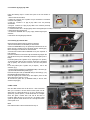
6. Cut the positive pole of ignition coil (on injector) near to the
connector. (fig.1)
7. Connect the red and blue wire (of GRIPONE cable) to the A end (fig.
1) by the heatshrincable head junction (fig. 2).
8. Connect the yellow wire (of GRIPONE cable) to the B end (fig. 1) by
the heatshrincable head junction (fig. 3).
9. Cut the negative pole of other coil (or other injector). Don’t use the
same coil chosen in steps 6, 7 and 8.
10. Connect the green wire (of GRIPONE cable) to the two ends
created in step 9 (fig.4)
2.3 Main switch
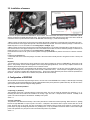
Onto the cable included into the kit there is a lever switch that
allow you to activate or not the traction control system. On the
switch there is a thread that allow you to fix it to the stirrup in a
specific way (see the picture ). On the thread there is a elongate
furrow who guide a washer with a tab. Tab fix the verse of
mounting. When the lever is set to the left the traction control
system is operative. When the lever is set to the right the traction
control system is off.
NOTE
Even with the traction control unactive the ECU stay on.