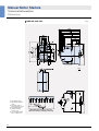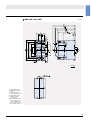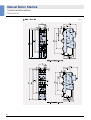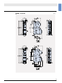
1
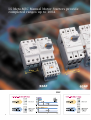
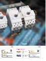
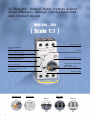
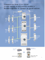
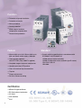
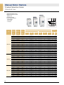
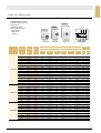
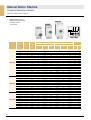
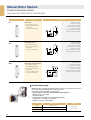
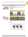
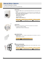
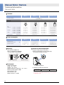
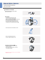
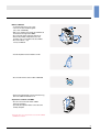
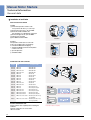
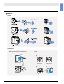
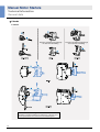
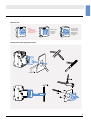
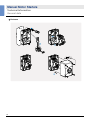
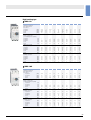
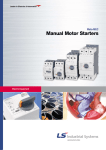
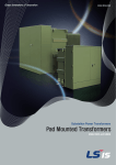
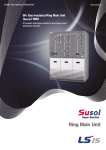
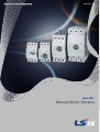
www.lsis.com
Meta-MEC
Manual Motor Starters
LS Meta-MEC Manual Motor Starters provide
completed ranges up to 100A
m
45 m
m
55 m
32AF
2
mm
45
m
70 m
63AF
100AF
3
LS Meta-MEC Manual Motor Starters deliver
more efficiency through various functions
and compact design
Finger safe terminals
Front mounted auxiliary
contact
Dial cover
Easy mounting onto DIN-rails
Large scale for current setting
Handle Lock device(Off position)
Auxiliaries are just snapped on:
easy, fast, without tools
Three position operator handle:
ON-OFF-TRIP
(Only 100AF is applied)
Dial cover lock device
Test trip device for checks of the
trip mechanism
Identification labels
45 mm
Handle Lock
4
Dial cover
Terminals
MMS-32
MMS-63
MMS-100
Screw
Lug
Lug
Common use from 32 to 100AF
A wide variety of accessories enables a
flexible response to changes in specifications
Front mounting
auxiliary switch
Dial cover
(FX)
Side mounting
Shunt release
Side
mounting
auxiliary
switch
(LX)
(RS)
(LX)
Side mounting
Undervoltage
release
Side
mounting
auxiliary
switch
Side
mounting
alarm
switch
(Any time)
(LX)
(LA)
(RU)
Side mounting
Undervoltage
release with
Switch
(RUX)
Side
mounting
alarm
switch
Side mounting
alarm switch
(Instantaneous)
(LX)
(LAM)
Direct adaptor
(Mini-MC)
Mini-MC (9~16A)
Direct adaptor
(Metasol/Susol-MC)
Metasol : MC-6a~100a
Susol-MC : 9~95
5
Function
�
Protection of group installation
�
Protection of circuits
�
Motor protection
�
Starter protection
�
Wide range of ambient
temperature compensation
�
Phase failure protection
Feature
�
45mm width up to 32A, 55mm width up to
63A and 70mm width rated to 100amps
�
Three position operator :
ON-OFF-TRIP (Only 100AF is applied)
�
Complete range of common accessories
�
Handle lock in the OFF position
�
Class 10 overload trip characteristics
�
Trip test
�
Finger safe terminal
�
Din rail & Screw mounting
Certification
6
�
KEMA CB type certificate
�
EC-Declaration of conformity
�
UL listed
�
CSA certified
�
CCC
Standard
�
Comply with the specifications in accordance with
IEC 60947-2 & IEC 60947-4-1
UL508 (Manual motor controller)
UL508 (Combination motor controller type E starter)
CSA C22.2 NO.14
GB14048
Contents
Product Selection Guide
Quick selection table ... IEC rating
8
Standard type
10
High breaking type
11
Instantaneous type
12
Accessories
13
Technical Information
General data
18
IEC performance data (Motor protection)
27
Manual motor controller
(UL 508, CSA C22.2 as Manual motor controllers)
31
Manual Motor Controller (UL508)
33
Type '2' coordination according to IEC 947-4-1
35
Time/Current characteristic
36
Thermal limit on short circuit for MMS
37
Dimensions
40
7
Manual Motor Starters
Product Selection Guide
Quick selection table ... IEC rating
Frame
Type
32AF
Current adjustable type
Instantaneous type
Breaking capacity
Handle Type
Number of poles
Rated operational voltage (Ue)
Rated frequency
Rated insulation voltage (Ui)
Rated impulse voltage (Uimp)
Utilization category
IEC 60 947-2 (Breaker)
IEC 60 947-4 (Motor starter)
Mechanical endurance (Operating)
Electrical endurance (Cycles)
Max operating frequency per hour (Ope./h)
Temperature compensation (Operation)
Instantaneous short circuit release
Overload protection
Phase failure function
Trip indicating function
Test function
Weight (g)
Rated
Thermal release
Rated operational
breaking
Adjustment
current (Ie)
range (A)
capacity
(kA)
0.16
0.25
0.4
0.63
1
1.6
2.5
4
6
8
10
13
17
22
26
32
40
50
63
65
75
90
100
8
0.1~0.16
0.16~0.25
0.25~0.4
0.4~0.63
0.63~1
1~1.6
1.6~2.5
2.5~4
4~6
5~8
6~10
9~13
11~17
14~22
18~26
22~32
28~40
34~50
45~63
47~65
55~75
70~90
80~100
MMS-32S
Standard
Toggle
MMS-32H
MMS-32HI
High breaking
Rotary
3
Up to 690V
50/60 Hz
690V
6kV
Cat. A
AC 3
100,000
100,000
25
-20 ~ +60℃
13 × Ie max.
�
�
×
�
3
Up to 690V
50/60 Hz
690V
6kV
Cat. A
AC 3
100,000
100,000
25
-20 ~ +60℃
13 × Ie max.
�
�
×
�
320
220V
240V
230V
415V
400V
360
460V
440V
525V
500V
690V
600V
220V
240V
230V
415V
400V
460V
440V
525V
500V
690V
600V
Icu
Ics
Icu
Ics
Icu
Ics
Icu
Ics
Icu
Ics
Icu
Ics
Icu
Ics
Icu
Ics
Icu
Ics
Icu
Ics
100
100
100
100
100
100
100
100
100
100
100
100
50
40
40
30
20
-
100
100
100
100
100
100
100
100
100
100
100
100
38
30
30
22
15
-
100
100
100
100
100
100
100
100
100
100
50
50
20
15
15
15
10
-
100
100
100
100
100
100
100
100
100
100
38
38
15
11
11
11
8
-
100
100
100
100
100
100
100
50
15
15
15
10
10
8
8
6
5
-
100
100
100
100
100
100
100
38
11
11
11
8
8
6
6
4
3
-
100
100
100
100
100
100
50
15
10
10
6
6
6
6
5
5
4
-
100
100
100
100
100
100
38
11
8
8
5
5
5
5
4
4
3
-
100
100
100
100
100
3
3
3
3
3
3
3
3
3
3
3
2
-
100
100
100
100
100
3
3
3
3
3
3
3
3
3
3
3
2
-
100
100
100
100
100
100
100
100
100
100
100
100
100
100
100
100
100
-
100
100
100
100
100
100
100
100
100
100
100
100
100
100
100
100
100
-
100
100
100
100
100
100
100
100
100
100
100
100
50
50
50
50
40
-
100
100
100
100
100
100
100
100
100
100
100
100
38
38
38
38
30
-
100
100
100
100
100
100
100
100
100
50
50
50
20
20
20
20
15
-
100
100
100
100
100
100
100
100
100
38
38
38
15
15
15
15
11
-
100
100
100
100
100
100
100
100
100
50
50
42
10
10
10
10
8
-
100
100
100
100
100
100
100
100
100
38
38
32
8
8
8
8
6
-
100
100
100
100
100
100
8
8
6
6
6
6
4
4
4
4
3
-
100
100
100
100
100
100
8
8
6
6
6
6
4
4
4
4
3
-
63AF
100AF
MMS-63S
Standard
Rotary
MMS-63H
MMS-63HI
High breaking
Rotary
MMS-100S
Standard
Rotary
MMS-100H
MMS-100HI
High breaking
Rotary
3
Up to 690V
50/60 Hz
1,000V
8kV
Cat. A
AC 3
50,000
25,000
25
-20 ~ +60℃
13 × Ie max.
�
�
×
�
3
Up to 690V
50/60 Hz
1,000V
8kV
Cat. A
AC 3
50,000
25,000
25
-20 ~ +60℃
13 × Ie max.
�
�
×
�
3
Up to 690V
50/60 Hz
1,000V
8kV
Cat. A
AC 3
50,000
25,000
25
-20 ~ +60℃
13 × Ie max.
�
�
�
�
3
Up to 690V
50/60 Hz
1,000V
8kV
Cat. A
AC 3
50,000
25,000
25
-20 ~ +60℃
13 × Ie max.
�
�
�
�
1,000
220V
240V
230V
415V
400V
460V
440V
1,000
525V
500V
690V
600V
220V
240V
230V
415V
400V
460V
440V
2,200
525V
500V
690V
600V
220V
240V
230V
415V
400V
460V
440V
2,200
525V
500V
690V
600V
220V
240V
230V
415V
400V
460V
440V
525V
500V
690V
600V
Icu Ics Icu Ics Icu Ics Icu Ics Icu Ics Icu Ics Icu Ics Icu Ics Icu Ics Icu Ics Icu Ics Icu Ics Icu Ics Icu Ics Icu Ics Icu Ics Icu Ics Icu Ics Icu Ics Icu Ics
- - - - - - - - - - - - - - - - - - - - - - - - - - - - - - - - - - - - - - - - - - - - - - - - - - - - - - - - - - - - - - - - - - - - - - - - - - - - - - - - - - - - - - - - - - - - - - - - - - - - - - - - - - - - - - - - - - - - - - - - - - - - - - - - - - - - - - - - - - - - - - - - - - - - - - - - - - - - - - - - - - - - - - - - - - - - - - - - - - - - - - - - - - - - - - - - - - - - - - - - - - - - - - - - - - - - - - - - - - - - - - - - - - - - - - - - - - - - - - - - - - - - - - - - - - - - - - - - - - - - - - - - - - - - - - - - - - 100 100 100 100 15 12 10 8 4 3 100 100 100 100 50 38 50 38 6 5
- - - - - - - - - - - - - - 100 100 50 38 10 8 6 5 4 3 100 100 100 100 50 38 42 32 6 5
100
50
50
50
50
50
50
50
-
100
38
38
38
38
38
38
38
-
25
25
25
25
25
25
25
25
-
19
19
19
19
19
19
19
19
-
10
10
10
10
10
10
10
10
-
8
8
8
8
8
8
8
8
-
6
6
6
6
6
6
6
6
-
5
5
5
5
5
5
5
5
-
4
4
4
4
4
4
4
4
-
3
3
3
3
3
3
3
3
-
100
100
100
100
100
100
100
75
-
100
100
100
100
100
100
100
50
-
50
50
50
50
50
50
50
35
-
50
50
50
50
50
50
50
27
-
50
50
35
35
35
35
35
25
-
38
38
27
27
27
27
27
19
-
12
12
12
10
10
10
10
6
-
9
9
9
8
8
8
8
5
-
5
5
5
5
5
5
5
3
-
5
5
5
5
5
5
5
3
-
100
100
100
100
100
100
100
100
100
100
100
100
100
100
100
100
100
100
100
100
50
50
50
50
50
50
50
50
50
50
38
38
38
38
38
38
38
38
38
38
40
40
40
40
40
40
40
40
40
40
30
30
30
30
30
30
30
30
30
30
25
25
25
15
15
12
12
8
8
8
19
19
19
11
11
9
9
6
6
6
10
10
10
10
6
6
6
5
5
5
8
8
8
8
5
5
5
4
4
4
100
100
100
100
100
100
100
100
100
100
100
100
100
100
100
100
100
100
100
100
100
100
100
100
100
100
100
75
75
75
100
50
50
50
50
50
50
50
50
50
50
50
50
50
50
50
50
50
50
50
38
38
38
38
38
38
38
38
38
38
35
35
35
25
20
15
15
12
12
12
27
27
27
19
15
11
11
9
9
9
12
12
12
12
12
10
8
6
6
6
9
9
9
9
9
8
6
6
6
6
9
Manual Motor Starters
Product Selection Guide
Standard type
∙Adjustable thermal release
∙Magnetic release 13 Ie max.
∙Trip class 10
∙Protective function
∙Phase-failure protection
- phase-failure
- short circuit
- overload
MMS-32S
Type
MMS-32S
MMS-63S
MMS-100S
10
Rated
Thermal
Magnetic
operational
release
release
current
Adjustment Operating
Ie
range
current
[A]
[A]
[A]
MMS-63S
MMS-100S
Switching of 3 phase AC motors, AC-2, AC-3
3-phase [kW] (50/60Hz)
3-phase [HP] (60Hz)
230V
400V
690V
230V
460V
400/415V
575V
Icu
Ics
[kA]
[kA]
0.16
0.1...0.16
2.1
-
0.02
-
-
-
-
100
100
0.25
0.16...0.25
3.3
0.03
0.06
-
-
-
-
100
100
0.4
0.25...0.4
5.2
0.06
0.09
-
-
-
-
100
100
0.63
0.4...0.63
8.2
0.09
0.12
0.25
-
-
-
100
100
1
0.63...1.0
13
0.12
0.25
0.55
-
1/2
1/2
100
100
1.6
1.0...1.6
20.8
0.25
0.55
1.1
1/3
3/4
1
100
100
2.5
1.6...2.5
32.5
0.37
0.75
1.5
1/2
1½
1½
100
100
4
2.5...4.0
52
0.75
1.5
3
1
2
3
100
100
6
4...6
78
1.5
2.2
4
1½
5
5
100
100
8
5...8
104
1.5
3
5.5
2
5
5
100
100
10
6...10
130
3
4
7.5
3
7½
10
50
38
13
9...13
169
3
5.5
11
3
7½
10
50
38
17
11...17
221
4
7.5
11
5
10
15
20
15
22
14...22
286
4
7.5
15
7½
15
20
15
11
26
18...26
338
5.5
11
18.5
7½
15
20
15
11
32
22...32
416
7.5
15
22
10
20
30
15
11
40
28~40
520
7.5
18.5
30
15
30
40
10
8
10
6~10
130
3
4
7.5
3
7½
10
100
100
13
9~13
169
3
5.5
11
3
7½
10
50
38
17
11~17
221
4
7.5
11
5
10
15
25
19
22
14~22
286
4
7.5
15
7½
15
20
25
19
26
18~26
338
5.5
11
18.5
10
20
25
25
19
32
22~32
416
7.5
15
22
10
25
30
25
19
40
28~40
520
7.5
18.5
30
15
30
40
25
19
50
34~50
650
11
22
45
15
40
50
25
19
63
45~63
819
15
30
55
20
50
60
25
19
65
47~65
845
15
30
55
20
50
60
25
19
17
11~17
221
4
7.5
11
5
10
15
50
38
22
14~22
286
4
7.5
15
7½
15
20
50
38
26
18~26
338
5.5
11
18.5
10
20
25
50
38
32
22~32
416
7.5
15
22
10
25
30
50
38
40
28~40
520
7.5
18.5
30
15
30
40
50
38
50
34~50
650
11
22
45
15
40
50
50
38
63
45~63
819
15
30
55
20
50
60
50
38
75
55~75
975
22
37
63
25
60
75
50
38
90
70~90
1170
30
45
75
30
75
100
50
38
100
80~100
1300
30
45
90
40
75
100
50
38
High breaking type
∙Adjustable thermal release
∙Magnetic release 13 Ie max.
∙Trip class 10
∙Protective function
∙Phase-failure protection
- phase-failure
- short circuit
- overload
MMS-32H
Type
MMS-32H
MMS-63H
MMS-100H
Rated
Thermal
operational
release
current
Adjustment
Ie
range
[A]
[A]
Magnetic
release
Operating
current
[A]
MMS-63H
MMS-100H
Switching of 3 phase AC motors, AC-2, AC-3
3-phase [kW] (50/60Hz)
3-phase [HP] (60Hz)
230V
400V
690V
230V
460V
400/415V
575V
Icu
Ics
[kA]
[kA]
0.16
0.1...0.16
2.1
-
0.02
-
-
-
-
100
100
0.25
0.16...0.25
3.3
0.03
0.06
-
-
-
-
100
100
0.4
0.25...0.4
5.2
0.06
0.09
-
-
-
-
100
100
0.63
0.4...0.63
8.2
0.09
0.12
0.25
-
-
-
100
100
1
0.63...1.0
13
0.12
0.25
0.55
-
1/2
1/2
100
100
1.6
1.0...1.6
20.8
0.25
0.55
1.1
1/3
3/4
1
100
100
2.5
1.6...2.5
32.5
0.37
0.75
1.5
1/2
1½
1½
100
100
4
2.5...4.0
52
0.75
1.5
3
1
2
3
100
100
6
4...6
78
1.5
2.2
4
1½
5
5
100
100
8
5...8
104
1.5
3
5.5
2
5
5
100
100
10
6...10
130
3
4
7.5
3
7½
10
100
100
13
9...13
169
3
5.5
11
3
7½
10
100
100
17
11...17
221
4
7.5
11
5
10
15
50
38
22
14...22
286
4
7.5
15
7½
15
20
50
38
26
18...26
338
5.5
11
18.5
7½
15
20
50
38
32
22...32
416
7.5
15
22
10
20
30
50
38
40
28~40
520
7.5
18.5
30
15
30
40
40
30
10
6~10
130
3
4
7.5
3
7½
10
100
100
13
9~13
169
3
5.5
11
3
7½
10
100
100
17
11~17
221
4
7.5
11
5
10
15
50
50
22
14~22
286
4
7.5
15
7½
15
20
50
50
26
18~26
338
5.5
11
18.5
10
20
25
50
50
32
22~32
416
7.5
15
22
10
25
30
50
50
40
28~40
520
7.5
18.5
30
15
30
40
50
50
50
34~50
650
11
22
45
15
40
50
50
50
63
45~63
819
15
30
55
20
50
60
50
50
65
47~65
845
15
30
55
20
50
60
35
27
17
11~17
221
4
7.5
11
5
10
15
100
100
22
14~22
286
4
7.5
15
7½
15
20
100
50
26
18~26
338
5.5
11
18.5
10
20
25
100
50
32
22~32
416
7.5
15
22
10
25
30
100
50
40
28~40
520
7.5
18.5
30
15
30
40
100
50
50
34~50
650
11
22
45
15
40
50
100
50
63
45~63
819
15
30
55
20
50
60
100
50
75
55~75
975
22
37
63
25
60
75
75
50
90
70~90
1170
30
45
75
30
75
100
75
50
100
80~100
1300
30
45
90
40
75
100
75
50
11
Manual Motor Starters
Product Selection Guide
Instantaneous type
∙Without thermal releases
∙Magnetic release 13 Ie max.
∙Protective function
- short circuit
MMS-32HI
Type
MMS-32HI
MMS-63HI
MMS-100HI
12
Rated
Thermal
operational
release
current
Adjustment
Ie
range
[A]
[A]
Magnetic
release
Operating
current
[A]
MMS-63HI
MMS-100HI
Switching of 3 phase AC motors, AC-2, AC-3
3-phase [kW] (50/60Hz)
3-phase [HP] (60Hz)
230V
400V
690V
230V
460V
400/415V
575V
Icu
Ics
[kA]
[kA]
0.16
-
2.1
-
0.02
-
-
-
-
100
100
0.25
-
3.3
0.03
0.06
-
-
-
-
100
100
0.4
-
5.2
0.06
0.09
-
-
-
-
100
100
0.63
-
8.2
0.09
0.12
0.25
-
-
-
100
100
1
-
13
0.12
0.25
0.55
-
1/2
1/2
100
100
1.6
-
20.8
0.25
0.55
1.1
1/3
3/4
1
100
100
2.5
-
32.5
0.37
0.75
1.5
1/2
1½
1½
100
100
4
-
52
0.75
1.5
3
1
2
3
100
100
6
-
78
1.5
2.2
4
1½
5
5
100
100
8
-
104
1.5
3
5.5
2
5
5
100
100
10
-
130
3
4
7.5
3
7½
10
100
100
13
-
169
3
5.5
11
3
7½
10
100
100
17
-
221
4
7.5
11
5
10
15
50
38
22
-
286
4
7.5
15
7½
15
20
50
38
26
-
338
5.5
11
18.5
7½
15
20
50
38
32
-
416
7.5
15
22
10
20
30
50
38
40
28~40
520
7.5
18.5
30
15
30
40
40
30
10
-
130
3
4
7.5
3
7½
10
100
100
13
-
169
3
5.5
11
3
7½
10
100
100
17
-
221
4
7.5
11
5
10
15
50
50
22
-
286
4
7.5
15
7½
15
20
50
50
26
-
338
5.5
11
18.5
10
20
25
50
50
32
-
416
7.5
15
22
10
25
30
50
50
40
-
520
7.5
18.5
30
15
30
40
50
50
50
-
650
11
22
45
15
40
50
50
50
63
-
819
15
30
55
20
50
60
50
50
65
47~65
845
15
30
55
20
50
60
35
27
100
17
-
221
4
7.5
11
5
10
15
100
22
-
286
4
7.5
15
7½
15
20
100
50
26
-
338
5.5
11
18.5
10
20
25
100
50
32
-
416
7.5
15
22
10
25
30
100
50
40
-
520
7.5
18.5
30
15
30
40
100
50
50
-
650
11
22
45
15
40
50
100
50
63
-
819
15
30
55
20
50
60
100
50
75
-
975
22
37
63
25
60
75
75
50
90
-
1170
30
45
75
30
75
100
75
50
100
-
1300
30
45
90
40
75
100
75
50
Accessories (Electrical Auxiliaries)
Type
FX...
Description
Auxiliary Switch
Connection diagram
1NO1NC
2NO
2NC
1NO1NC
2NO
2NC
∙Front mounting
∙2-pole
∙One front mounting module
per circuit breaker
LX...
Auxiliary Switch
∙Side mounting on the left
∙2-pole
∙One side mounting module
per circuit breaker
LA...
Any Trip Alarm Switch
1NO1NC
2NC
∙Operates in case of trip
∙Side mounting on the left
∙2-pole
∙Set LA first in case of using
LX together
(MMS-63 can not accept
LX and LA together)
∙For MMS-32 and MMS-63/100
products are separated.
LAM...
Magnetic Trip Alarm Switch
1NO1NC
2NO
2NC
∙Operates in case of short circuit
accidents that is over 20 times of the
rated current
∙Side mounting on the left
∙2-pole
∙Set LAM first in case of using
LX together
13
Manual Motor Starters
Product Selection Guide
Accessories (Electrical Auxiliaries)
Type
RS...
Description
Connection diagram
24V 50Hz / 28V 60Hz
110V 50Hz / 120V 60Hz
200V 50Hz / 200~220V 60Hz
220~230V 50Hz / 240~260V 60Hz
240V 50Hz / 277V 60Hz
380~400V 50Hz / 440~460V 60Hz
415~440V 50Hz / 460~480V 60Hz
Shunt release
∙Side mounting on the right
∙One side mounting module per
circuit breaker.
∙Can not use with RU or RUX
RU...
24V 50Hz / 28V 60Hz
Undervoltage release
110V 50Hz / 120V 60Hz
∙Side mounting on the right
200V 50Hz / 200~220V 60Hz
∙One side mounting module per
220~230V 50Hz / 240~260V 60Hz
circuit breaker.
240V 50Hz / 277V 60Hz
∙Can not use with RU or RUX
380~400V 50Hz / 440~460V 60Hz
415~440V 50Hz / 460~480V 60Hz
RUX...
24V 50Hz / 28V 60Hz
Undervoltage release with Switch
110V 50Hz / 120V 60Hz
∙Side mounting on the right
200V 50Hz / 200~220V 60Hz
∙Include 2NO Auxiliary contact
220~230V 50Hz / 240~260V 60Hz
∙One side mounting module per
240V 50Hz / 277V 60Hz
circuit breaker.
380~400V 50Hz / 440~460V 60Hz
∙Can not use with RU or RUX
415~440V 50Hz / 460~480V 60Hz
∙Can not attach to MMS-32S
� E-Handle (Rotary-type)
MMS E-Handle is a Rotary-type Handle accessory which can be attached to the front to
control and verify the ON, TRIP, OFF condition of Manual
Motor Starters under the situation of closing panel.
∙Application Model : MMS-32H/HI,MMS-63S/H/HI, MMS-100S/H/HI
∙Operation temp. : -20~ +60°C
∙CE and UL certified
∙Degree of protection : IP65 or UL 50 Type 3R(Separately)
∙Locking device : Lockable in on/off position
∙Material of insulation : Plastic(PA66)
Type
Application MMS
MEH-32
MMS-32H, 32HI
MEH-63
MMS-63S, 63H, 63HI
MEH-100
MMS-100S, 100H, 100HI
Remarks
Length of shaft :
115 or 315mm
14
� Phase Bus System
It is a device for a parallel connection with power terminals in the circuit lined up by MMS,
and it can provides the solution "Simple wiring”and“Compact wiring space”.
∙Application Model : MMS-32, 63
∙CE and UL certified
∙Safety Cover built-in
∙RoHS compliance
Type
Number of
Terminals
Application MMS
PB-322
2
PB-323
3
Rated
current
PBPC-32
MMS-32S, 32H, 32HI
63A
PB-324
4
PB-325
5
PB-632
(32for S, H)
2
MMS-63S, 63H, 63HI
108A
PB-633
LTB-32
PB-325
Safety cover
attached
PBPC-63
3
Model
LTB-32
Pole
3P
Mounting location
Upstream
IP degree of protection
IP20 according to IEC 60529
Rated insulation voltage (Ui)
690V according to IEC 60947-1
Rated operational current (Ie)
63A
Terminal torque
1.7 N.m- on screw clamp terminals
� Diagram
L1 L2 L3
1
2
3
5
4
M
6
7
9
11
8
10
M
12
13
15 17
14
16
18
M
15
Manual Motor Starters
Product Selection Guide
Accessories (Electrical Auxiliaries)
� Enclosure
Case cover of MMS enclosure is specifically designed with dust-proof and corrosive-proof
structure.
Therefore, it is the optimum product to use in dusty areas such as cement plants, cotton
mills as well as in the presence of corrosive gas or liquid (excl. explosive, flammable gas)
such as fertilizer, refinery, and plating plant.
∙Application Model: MMS-32H/HI
∙Operation temp. : -20~ +60℃
∙CE and UL certified
∙Degree of protection : IP65
∙Material of insulation :Plastic(ABS)
Type
Application MMS
Remarks
EPH-32
MMS-32H, 32HI
Surface mount
Dial Cover
� Dial Cover
Dial cover is used to protect the set value from the operation that is not intended.
It is supplied as standard for all MMS.
∙Application Model : MMS-32, 63,100 (All types)
Sealing
� Insulation Barrier
Insulation barrier is used to enlarge the creepage distance and clearance to meet the
requirement of UL.
∙Application Model : MMS-100
Type
Application MMS
IB100
MMS-100S, 100H, 100HI
� Screw mounting holder
32AF MMS is only for DIN rail mountable by itself. Screw mounting holder is used to
mount MMS on a panel by screws.
∙Application Model : MMS-32
16
Type
Application MMS
Remarks
MP-32
MMS-32S, 32H, 32HI
For M4 screw
� Direct adaptor and Mounting unit
Direct adaptor , DA
Direct adaptor is used to connect MMS directly with a contactor
Mounting unit , MU
This device is attached module to connect joined MMS with a contactor
∙Application Model : MMS+ Susol contactor(MC-9~95), Mini contactor
Direct adaptor
Frame
DA-16
DA-18
Name
Mounting
unit
DA-16SA
MMS-32S + GMC-6M~16M
DA-16SD
MMS-32S + GMD-6M~16
DA-16HA
MMS-32H + GMC-6M~16M
DA-16HD
MMS-32H + GMD-6M~16M
DA-18SA
MMS-32S + MC-6a~18a
DA-18SD
MMS-32S + MC-6a~18a DC
DA-18HA
MMS-32H + MC-6a~18a
DA-18HD
MU-45
DA-22SA
DA-22
DA-32
DA-63
MMS-32H + MC-6a~18a DC
DA-22SD
MMS-32S + MC-9b~22b DC
DA-22HA
MMS-32H + MC-9b~22b
DA-22HD
MMS-32H + MC-9b~22b DC
DA-32SA
MMS-32S + MC-9~32(32a, 40a)
DA-32SD
MMS-32S + MC-9~32(32a, 40a) DC
DA-32HA
MMS-32H + MC-9~32(32a, 40a)
DA-32HD
MMS-32H + MC-9~32(32a, 40a) DC
DA-63A
MMS-63AF + MC-35~63 (50a, 65a)
DA-95A
Applying
Contactor
Mini-MC
Metasol MC
MMS-32S + MC-9b~22b
MU-55
DA-63D
DA-95
Combined devices
MMS-63AF + MC-35~63 (50a, 65a) DC
MU-70
DA-95D
MMS-100AF + MC-65~95 (75a, 85a, 100a)
MMS-100AF + MC-65~95 (75a, 85a, 100a) DC
Susol,
Metasol MC
Susol,
Metasol MC
(Lug Type
Only)
MMS-100
MMS-63
MMS-32
MC-95
MC-63
MC-32
Note) MMS and Contactor connected with Direct adaptor.
17
Manual Motor Starters
Technical Information
General data
� Terminals
MMS32S
MMS32H
Conformity to standards
MMS63S, 63H
MMS100S, 100H
IEC60947
UL508, UL508 Type E
Approvals
CE, UL
Terminal parts
Wire
Single-core
Stranded
Flexible
1 conductor
[㎟] / [AWG]
1...10 / 18...8
1...10 / 18...8
0.75...35 / 18...2
2.5...70 / 12...2/0
2 conductor
[㎟] / [AWG]
1...6 / 18...10
1...6 / 18...10
0.75...25 / 18...4
2.5...50 / 12...1/0
1 conductor
[㎟] / [AWG]
1...6 / 18...10
1...6 / 18...10
0.75...35 / 18...2
2.5...70 / 12...2/0
2 conductor
[㎟] / [AWG]
1...6 / 18...10
1...6 / 18...10
0.75...25 / 18...4
2.5...50 / 12...1/0
1 conductor
[㎟] / [AWG]
1...6 / 18...10
1...6 / 18...10
0.75...25 / 18...4
2.5...50 / 12...1/0
2 conductor
[㎟] / [AWG]
0.75...4 / 18...10
0.75...4 / 18...10
0.75...16 / 18...6
2.5...35 / 10...2
[Nm] / [Ib-in]
0.8...2.5 / 7...22
0.8...2.5 / 7...22
3...4.5 / 26...39
4...6 / 35...53
MMS32S
MMS32H
MMS63S, 63H
MMS100S, 100H
Tightening torque
� Power consumption
Total power loss Pv
Circuit breaker at rated load
[W]
operating temperature
In = 0.16~1.6A : 4.4
In = 0.16~1.6A : 4.4
In = 10~22A : 10.2
In = 17~32A : 15
In = 2.5~26A : 7.4
In = 2.5~26A : 7.4
In = 26~63A : 9.7
In = 40~63A : 21.8
In = 32A
In = 32A
: 4.0
� Mounting
In = 75~100A : 17.8
� Caution for thermal adjustments
35mm DIN rail for MMS32~63
35mm or 75mm DIN rail for MMS100
- use 15mm depth for 35mm DIN rail
Operating positions
: 4.0
1.Keep the setting range as shown below.
2.Moving counterclockwise out of the setting range
may cause the damage of the device.
DIN rail mounting
� Environment
Ambient air temperature
storage : - 50…+ 80 �C
operation : - 20…+ 60 �C
Ambient temperature compensation : - 20…+ 60 �C
Maximum operating altitude : 2000m
Protection degree : IP20
Shock resistance : 25g
Vibration resistance : 5~150Hz
18
Dial setting method
3. Calibration by ambient air temperature
A : set to one
point lower
-20℃
B : set to one
point higher
Calibrated automatically
-5℃
+40℃
+60℃
In case of using out of the standard air temperature range(-5°C~+40°C) it needs to
be calibrated by one point
� Auxiliaries
Auxiliary contacts for front
mounting
FX...
Auxiliary contacts for left side
mounting
LX...
Alarm switch for left side
mounting
LA...
Rated thermal current / th
at 40℃ ambient temperature
[A]
5
10
10
at 60℃ ambient temperature
[A]
3
6
6
Contact class coordination
according to NEMA
(UL/CSA-Standards)
AC
A600
A600
A600
DC
Q300
Q300
Q300
Back-up fuses gG, gL
[A]
Rated supply current
[V]
-
240
24
240
24
AC-15:
[A]
-
3
6
4
6
4
DC-13:
[V]
24
220
24
220
24
220
[A]
1
0.1
2
0.25
2
Weight (g)
16
16
18
16
30
240
0.25
40
Terminal parts
Wire
Single-core
Stranded
Pozidriv size 2
1 conductor
[㎟] / [AWG]
2 conductor
1 conductor
2 conductor
Tightening torque
0.5...2.5 / 20...14
0.5...2.5 / 20...14
[㎟] / [AWG]
-
0.5...2.5 / 20...14
[㎟] / [AWG]
0.5...4 / 20...10
0.5...4 / 20...10
[㎟] / [AWG]
0.75...2.5 / 18...14
0.75...2.5 / 18...14
[Nm] / [Ib-in]
0.8...1.2 / 7...10
0.8...1.2 / 7...10
Undervoltage release
for right side mounting
RU...
Undervoltage release with 2 auxiliary
contacts for right side mounting
RUX...
Shunt release
for right side mounting
RS...
Actuating voltage
Pull-in
0.7...1.1×Us
Drop-out
0.85...1.1×Us
0.85...1.1×Us
0.7...0.35×Us
0.7...0.35×Us
Rated control voltage
min.:
24V 50Hz / 28V 60Hz
24V 50Hz / 28V 60Hz
24V 50Hz / 28V 60Hz
max.:
415~440V 50Hz / 460~480V 60Hz
415~440V 50Hz / 460~480V 60Hz
415~440V 50Hz / 460~480V 60Hz
Coil rating
Pull-in
8.5VA, 6W
8.5VA, 6W
8.5VA, 6W
Hold
3VA, 1.2W
3VA, 1.2W
3VA, 1.2W
-
20
20
18
30
40
Opening time (ms)
Weight (g)
Terminal parts
Wire
Single-core
Stranded
Tightening torque
Pozidriv size 2
1 conductor [㎟] / [AWG]
0.5...2.5 / 20...14
2 conductor [㎟] / [AWG]
0.5...2.5 / 20...14
1 conductor [㎟] / [AWG]
0.5...4 / 20...10
2 conductor [㎟] / [AWG]
0.75...2.5 / 18...14
[Nm] / [Ib-in]
0.8...1.2 / 7...10
19
Manual Motor Starters
Technical Information
General data
� Installation of auxiliaries
Be sure to turn off the main switch of MMS
before any other action.
MMS-32S/H/HI
�To install FX remove the cover ① first.
�2 each of LX can be installed together.
�Only one of auxiliaries among RU, RS and RUX can
be mounted on the right side of MMS.
�Do not give trip signal to RS longer than 10 sec.
�Refer to the possible combination chart for the
mounting of LX, LA and LAM on left side of MMS.
�Push the trip button before installation of LAM
�Remove the indicated part in the fig.
before the additional installation of LX
Separation of auxiliaries from MMS
�be sure to turn off the main switch of MMS
before the separation.
�push softly the separation button on the side
of the auxiliary and pull it.
※Please make sure to choose proper LA before use because LA for MMS-32
and MMS-63/100 is different.
20
MMS-63, 100S/H/HI
�To install FX remove the cover ① first.
�2 each of LX can be installed together.
(only 1 each for MMS-63)
�Only one of auxiliaries among RU, RS and RUX can
be mounted on the right side of MMS.
�Do not give trip signal to RS longer than 10 sec.
�Refer to the possible combination chart for the
mounting of LX, LA and LAM on left side of MMS.
�Do not use with LA-... (32)
It is only for MMS-32.
�Push the trip button before installation of LAM
�Do not install LA in the status of TRIP of MMS-100
�Remove the indicated part as shown in the above fig.
before the additional installation of LX
Separation of auxiliaries from MMS
�be sure to turn off the main switch of MMS
before the separation.
�push softly the separation button on the side of the
auxiliary and pull it.
※Please make sure to choose proper LA before use because LA for MMS-32
and MMS-63/100 is different.
21
Manual Motor Starters
Technical Information
General data
� Installation of auxiliaries
How to Install and reset RUX
Installing
(1) Check if the trip button of RUX is "UP" .
If not, push the side lever ① to come it up.
(2) Fit the both lower hooks ② into the MMS.
(3) Rotate the handle of MMS to the
20 to 30 degree ③ to ON direction and keep it.
(4) Fit the both upper hooks ④into the MMS.
(5) Input power to the RUX.
(6) Turn ON the handle of MMS.
Insulation
Resetting
The trip button of RUX does not come "UP"
in the event of tripping due to undervoltage.
To turn ON the MMS after the tripping
① turn OFF the MMS and check if the trip button
of RUX comes "UP" .
② push the trip button
③ turn ON the MMS
Insulation barrier
* Only for MMS-100
Reset
Dial cover
* For all MMS
Combination with mini contactors
Adaptor
MMS
+
Contactor model
DA-16SA
MMS-32S
+ GMC-6M~16M
DA-16SD
MMS-32S
+ GMD-6M~16M
DA-16HA
MMS-32H, 32HI
+ GMC-6M~16M
DA-16HD
MMS-32H, 32HI
+ GMD-6M~16M
DA-18SA
MMS-32S
+ MC-6a~18a
DA-18SD
MMS-32S
+ MC-6a~18a DC
DA-18HA
MMS-32H
+ MC-6a~18a
DA-18HD
MMS-32H
+ MC-6a~18a DC
DA-22SA
MMS-32S
+ MC-9b~22b
DA-22SD
MMS-32S
+ MC-9b~22b DC
DA-22HA
MMS-32H, 32HI
+ MC-9b~22b
DA-22HD
MMS-32H, 32HI
+ MC-9b~22b DC
DA-32SA
MMS-32S
+ MC-9~32(32a, 40a)
DA-32SD
MMS-32S
+ MC-9~32(32a, 40a) DC
DA-32HA
MMS-32H, 32HI
+ MC-9~32(32a, 40a)
DA-32HD
MMS-32H, 32HI
+ MC-9~32(32a, 40a) DC
DA-63A
MMS-63S, 63H, 63HI
+ MC-35~63(50a, 65a)
DA-63D
MMS-63S, 63H, 63HI
+ MC-35~63(50a, 65a) DC
DA-95A
MMS-100S, 100H, 100HI + MC-65~95(75a, 85a, 100a) /
DA-95D
MMS-100S, 100H, 100HI + MC-65~95(75a, 85a, 100a)
Lug Type Only
Note)
* RUX : can not attach to MMS-32S
Note)
DC / Lug Type Only
Possible combination chart
Please read this chart completely before installing the
auxiliaries.
Improper combination can cause electric
failure or accident.
22
Note) LA(32 on 63/100 is a sparate).
� E-Handle
Structure
Locking Device
When opening the panel door at ON position
Locking
Installation at OF, OFF position
Setting to regular position through turning the handle
Open Panel Door
On Position
(Vertical State)
Pushing
Off Position
(Horizontal State)
Locking
Releasing
23
Manual Motor Starters
Technical Information
General data
� E-Handle
Installation
Projection should be passed through
the hole when assembling
Restricted fact of Assembling
Assembling is available for MMS-63/100 with 4 holes on the main cover
which is produced after June, 2007 based on manufacturing date.
24
Projection should be passed through
the hole when assembling
Operating Test
※Caution
If trying to open the
door at ON or Trip
position, locking knob
can be damaged.
At On position
Panel door
can not be
opened
At Trip position
Panel door can
not be opened.
At Off position
Panel door can
be opened
Cutting off the shaft & applying the handle
25
Manual Motor Starters
Technical Information
General data
� Enclosure
26
IEC performance data (Motor protection)
Standard type
� MMS 32S
Rated operational current Ie
Switching of standard
three-phase motors
AC-2, AC-3
230/240V
400/415V
500V
690V
Back-up fuses
gG, gL,, only if Icc>Icu
( * = No back up fuse required)
230/240V
400/415V
440/460V
500V
690V
Ultimate short-circuit
breaking capacity Icu
230/240V
400/415V
440/460V
500V
690V
Rated service short-circuit
breaking capacity Ics
230/240V
400/415V
440/460V
500V
690V
[A]
0.16
0.25
0.4
0.63
1
1.6
2.5
4
6
8
10
13
17
22
26
32
40
[kW]
[kW]
[kW]
[kW]
0.02
-
0.03
0.06
-
0.06
0.09
-
0.09 0.12 0.18/0.25 0.37 0.55/0.75 1.1/1.5 1.5
0.12 0.18/0.25 0.37/0.55 0.75 1.1/1.5 2.2
3
0.25 0.37 0.55/0.75 1.1 1.5/2.2 3
3.7
0.25 0.37/0.55 0.75/1.1 1.5 2.2/3 3.7/4 5.5
2.2/3
3.7/4
4/5.5
7.5
3
5.5
7.5
11
3.7/4
7.5
11
11
4
7.5
11
15
5.5
11
15
18.5
7.5
15
18.5
22
7.5
18.5
22
30
[A]
[A]
[A]
[A]
[A]
*
*
*
*
*
*
*
*
*
*
*
*
*
*
*
*
*
*
*
*
*
*
*
*
*
*
*
*
*
20
*
*
*
50
35
*
*
50
40
40
*
*
50
50
50
*
*
63
63
63
*
80
63
63
63
*
80
80
80
63
*
100
80
80
63
125
100
100
80
63
125
100
100
80
63
125
100
100
80
63
160
125
100
80
63
[kA]
[kA]
[kA]
[kA]
[kA]
100
100
100
100
100
100
100
100
100
100
100
100
100
100
100
100
100
100
100
100
100
100
100
100
100
100
100
100
100
3
100
100
100
50
3
100
100
50
15
3
100
100
15
10
3
100
100
15
10
3
100
50
15
6
3
100
50
10
6
3
50
20
10
6
3
40
15
8
6
3
40
15
8
6
3
30
15
6
5
3
20
10
5
4
2
[kA]
[kA]
[kA]
[kA]
[kA]
100
100
100
100
100
100
100
100
100
100
100
100
100
100
100
100
100
100
100
100
100
100
100
100
100
100
100
100
100
3
100
100
100
38
3
100
100
38
11
3
100
100
11
8
3
100
100
11
8
3
100
38
11
5
3
100
38
8
5
3
38
15
8
5
3
30
11
6
5
3
30
11
6
5
3
22
11
4
4
3
15
8
3
3
2
� MMS 63S
Rated operational current Ie
Switching of standard
three-phase motors
AC-2, AC-3
230/240V
400/415V
500V
690V
Back-up fuses
gG, gL,, only if Icc>Icu
( * = No back up fuse required)
230/240V
400/415V
440/460V
500V
690V
Ultimate short-circuit
breaking capacity Icu
230/240V
400/415V
440/460V
500V
690V
Rated service short-circuit
breaking capacity Ics
230/240V
400/415V
440/460V
500V
690V
[A]
10
13
17
22
26
32
40
50
63
65
[kW]
[kW]
[kW]
[kW]
2.2/3
3.7/4
4/5.5
7.5
3
5.5
7.5
11
3.7/4
7.5
11
11
4
7.5
11
15
5.5
11
15
18.5
7.5
15
18.5
22
7.5
18.5
22
30
11
22
30
45
15
30
37
55
15
30
37
55
[A]
[A]
[A]
[A]
[A]
*
*
80
80
63
*
80
80
80
63
*
100
100
80
63
125
125
100
80
63
125
125
100
80
63
160
125
100
80
63
160
125
100
80
63
160
160
100
80
63
200
160
125
80
80
200
180
125
80
60
[kA]
[kA]
[kA]
[kA]
[kA]
100
100
15
10
4
100
50
10
6
4
100
25
10
6
4
50
25
10
6
4
50
25
10
6
4
50
25
10
6
4
50
25
10
6
4
50
25
10
6
4
50
25
10
6
4
50
25
10
6
4
[kA]
[kA]
[kA]
[kA]
[kA]
100
100
12
8
3
100
38
8
5
3
100
19
8
5
3
38
19
8
5
3
38
19
8
5
3
38
19
8
5
3
38
19
8
5
3
38
19
8
5
3
38
19
8
5
3
38
19
8
5
3
27
Manual Motor Starters
Technical Information
IEC performance data (Motor protection)
Standard type
� MMS 100S
Rated operational current Ie
Switching of standard
three-phase motors
AC-2, AC-3
230/240V
400/415V
500V
690V
Back-up fuses
gG, gL,, only if Icc>Icu
( * = No back up fuse required)
230/240V
400/415V
440/460V
500V
690V
Ultimate short-circuit
breaking capacity Icu
230/240V
400/415V
440/460V
500V
690V
Rated service short-circuit
breaking capacity Ics
230/240V
400/415V
440/460V
500V
690V
[A]
17
22
26
32
40
50
63
75
90
100
[kW]
[kW]
[kW]
[kW]
3.7/4
7.5
11
11
4
7.5
11
15
5.5
11
15
18.5
7.5
15
18.5
22
7.5
18.5
22
30
11
22
30
45
15
30
37
55
22
37
45
63
30
45
55
75
30
45
63
90
[A]
[A]
[A]
[A]
[A]
*
100
100
100
63
*
125
125
100
80
*
125
125
100
80
*
125
125
100
80
*
160
125
100
80
*
160
125
100
80
*
160
160
100
80
*
160
160
125
100
*
160
160
125
125
*
160
160
125
125
[kA]
[kA]
[kA]
[kA]
[kA]
100
50
40
25
10
100
50
40
25
10
100
50
40
25
10
100
50
40
15
10
100
50
40
15
6
100
50
40
12
6
100
50
40
12
6
100
50
40
8
5
100
50
40
8
5
100
50
40
8
5
[kA]
[kA]
[kA]
[kA]
[kA]
100
38
30
19
8
100
38
30
19
8
100
38
30
19
8
100
38
30
11
8
100
38
30
11
5
100
38
30
9
5
100
38
30
9
5
100
38
30
6
4
100
38
30
6
4
100
38
30
6
4
High breaking type
� MMS 32H
Rated operational current Ie
Switching of standard
three-phase motors
AC-2, AC-3
230/240V
400/415V
500V
690V
Back-up fuses
gG, gL,, only if Icc>Icu
( * = No back up fuse required)
230/240V
400/415V
440/460V
500V
690V
Ultimate short-circuit
breaking capacity Icu
230/240V
400/415V
440/460V
500V
690V
Rated service short-circuit
breaking capacity Ics
230/240V
400/415V
440/460V
500V
690V
[A]
0.16
0.25
0.4
0.63
[kW]
[kW]
[kW]
[kW]
0.02
-
0.03
0.06
-
0.06
0.09
-
0.09 0.12 0.18/0.25 0.37 0.55/0.75 1.1/1.5 1.5
0.12 0.18/0.25 0.37/0.55 0.75 1.1/1.5 2.2
3
0.25 0.37 0.55/0.75 1.1 1.5/2.2 3
3.7
0.25 0.37/0.55 0.75/1.1 1.5 2.2/3 3.7/4 5.5
[A]
[A]
[A]
[A]
[A]
*
*
*
*
*
*
*
*
*
*
*
*
*
*
*
*
*
*
*
*
*
*
*
*
*
*
*
*
*
*
*
*
*
*
35
*
*
*
*
40
*
*
*
*
50
[kA]
[kA]
[kA]
[kA]
[kA]
100
100
100
100
100
100
100
100
100
100
100
100
100
100
100
100
100
100
100
100
100
100
100
100
100
100
100
100
100
100
100
100
100
100
8
100
100
100
100
8
[kA]
[kA]
[kA]
[kA]
[kA]
100
100
100
100
100
100
100
100
100
100
100
100
100
100
100
100
100
100
100
100
100
100
100
100
100
100
100
100
100
100
100
100
100
100
8
100
100
100
100
8
Note) * = Short circuit proof up to 50 or 100kA. No back up fuse required.
28
1
1.6
2.5
4
6
8
10
13
17
22
26
32
40
2.2/3
3.7/4
4/5.5
7.5
3
5.5
7.5
11
3.7/4
7.5
11
11
4
7.5
11
15
5.5
11
15
18.5
7.5
15
18.5
22
7.5
1.8
22
30
*
*
80
63
63
*
*
80
80
63
*
*
80
80
63
*
100
80
80
63
*
125
100
80
63
*
125
100
80
63
*
125
100
80
63
*
160
125
100
80
100
100
100
100
6
100
100
50
50
6
100
100
50
50
6
100
100
50
42
6
100
50
20
10
4
100
50
20
10
4
100
50
20
10
4
100
50
20
10
4
100
40
15
8
3
100
100
100
100
6
100
100
38
38
6
100
100
38
38
6
100
100
38
32
6
100
38
15
8
4
100
38
15
8
4
100
38
15
8
4
100
38
15
8
4
100
30
11
6
3
High breaking type
� MMS 63H
Rated operational current Ie
Switching of standard
three-phase motors
AC-2, AC-3
230/240V
400/415V
500V
690V
Back-up fuses
gG, gL,, only if Icc>Icu
( * = No back up fuse required)
230/240V
400/415V
440/460V
500V
690V
Ultimate short-circuit
breaking capacity Icu
230/240V
400/415V
440/460V
500V
690V
Rated service short-circuit
breaking capacity Ics
230/240V
400/415V
440/460V
500V
690V
[A]
10
13
17
22
26
32
40
50
63
65
[kW]
[kW]
[kW]
[kW]
2.2/3
3.7/4
4/5.5
7.5
3
5.5
7.5
11
3.7/4
7.5
11
11
4
7.5
11
15
5.5
11
15
18.5
7.5
15
18.5
22
7.5
18.5
22
30
11
22
30
45
15
30
37
55
15
30
37
55
[A]
[A]
[A]
[A]
[A]
*
*
100
100
63
*
*
100
100
63
*
100
100
100
63
*
125
125
100
80
*
125
125
100
80
*
125
125
100
80
*
160
125
100
80
*
160
125
100
80
*
160
160
100
80
*
160
160
100
80
[kA]
[kA]
[kA]
[kA]
[kA]
100
100
50
50
6
100
100
50
42
6
100
50
50
12
5
100
50
50
12
5
100
50
35
12
5
100
50
35
10
5
100
50
35
10
5
100
50
35
10
5
100
50
35
10
5
75
35
25
6
3
[kA]
[kA]
[kA]
[kA]
[kA]
100
100
38
38
5
100
100
38
32
5
100
50
38
9
5
100
50
38
9
5
100
50
27
9
5
100
50
27
8
5
100
50
27
8
5
100
50
27
8
5
100
50
27
8
5
50
27
19
5
3
Note) * = Short circuit proof up to 50 or 100kA. No back up fuse required.
� MMS 100H
Rated operational current Ie
Switching of standard
three-phase motors
AC-2, AC-3
230/240V
400/415V
500V
690V
Back-up fuses
gG, gL,, only if Icc>Icu
( *= No back up fuse required)
230/240V
400/415V
440/460V
500V
690V
Ultimate short-circuit
breaking capacity Icu
230/240V
400/415V
440/460V
500V
690V
Rated service short-circuit
breaking capacity Ics
230/240V
400/415V
440/460V
500V
690V
[A]
17
22
26
32
40
50
63
75
90
100
[kW]
[kW]
[kW]
[kW]
3.7/4
7.5
11
11
4
7.5
11
15
5.5
11
15
18.5
7.5
15
18.5
22
7.5
18.5
22
30
11
22
30
45
15
30
37
55
22
37
45
63
30
45
55
75
30
45
63
90
[A]
[A]
[A]
[A]
[A]
*
*
125
100
80
*
*
125
125
80
*
*
125
125
80
*
*
160
125
80
*
*
160
160
80
*
*
160
160
100
*
*
200
160
100
*
*
200
160
125
*
*
200
160
160
*
*
200
160
160
[kA]
[kA]
[kA]
[kA]
[kA]
100
100
50
35
12
100
100
50
35
12
100
100
50
35
12
100
100
50
25
12
100
100
50
20
12
100
100
50
15
10
100
100
50
15
8
100
75
50
12
6
100
75
50
12
6
100
75
50
12
6
[kA]
[kA]
[kA]
[kA]
[kA]
100
100
38
27
9
100
50
38
27
9
100
50
38
27
9
100
50
38
19
9
100
50
38
15
9
100
50
38
11
8
100
50
38
11
6
100
50
38
9
6
100
50
38
9
6
100
50
38
9
6
Note) * = Short circuit proof up to 50 or 100kA. No back up fuse required.
29
Manual Motor Starters
Technical Information
IEC performance data (Motor protection)
High breaking type
� MMS 32HI
Rated operational current Ie
AC-2, AC-3
230/240V
400/415V
500V
690V
Back-up fuses
gG, gL,, only if Icc>Icu
( * = No back up fuse required)
230/240V
400/415V
440/460V
500V
690V
Ultimate short-circuit
breaking capacity Icu
230/240V
400/415V
440/460V
500V
690V
Rated service short-circuit
breaking capacity Ics
230/240V
400/415V
440/460V
500V
690V
[A]
0.16
0.25
0.4
0.63
1
1.6
2.5
4
6
8
10
13
17
22
26
32
40
[kW]
[kW]
[kW]
[kW]
0.02
-
0.03
0.06
-
0.06
0.09
-
0.09
0.12
0.25
0.25
0.12
0.18/0.25
0.37
0.37/0.55
0.18/0.25
0.37/0.55
0.55/0.75
0.75/1.1
0.37
0.75
1.1
1.5
1.5
3
3.7
5.5
2.2/3
3.7/4
4/5.5
7.5
3
5.5
7.5
11
3.7/4
7.5
11
11
4
7.5
11
15
5.5
11
15
18.5
7.5
15
18.5
22
7.5
18.5
22
30
[A]
[A]
[A]
[A]
[A]
*
*
*
*
*
*
*
*
*
*
*
*
*
*
*
*
*
*
*
*
*
*
*
*
*
*
*
*
*
*
*
*
*
*
35
*
*
*
*
40
*
*
*
*
50
*
*
80
63
63
*
*
80
80
63
*
*
80
80
63
*
100
80
80
63
*
125
100
80
63
*
125
100
80
63
*
125
100
80
63
*
160
125
100
80
[kA]
[kA]
[kA]
[kA]
[kA]
100
100
100
100
100
100
100
100
100
100
100
100
100
100
100
100
100
100
100
100
100
100
100
100
100
100
100
100
100
100
100
100
100
100
8
100
100
100
100
8
100
100
100
100
6
100
100
50
50
6
100
100
50
50
6
100
100
50
42
6
100
50
20
10
4
100
50
20
10
4
100
50
20
10
4
100
50
20
10
4
100
40
15
8
3
[kA]
[kA]
[kA]
[kA]
[kA]
100
100
100
100
100
100
100
100
100
100
100
100
100
100
100
100
100
100
100
100
100
100
100
100
100
100
100
100
100
100
100
100
100
100
8
100
100
100
100
8
100
100
100
100
6
100
100
38
38
6
100
100
38
38
6
100
100
38
32
6
100
38
15
8
4
100
38
15
8
4
100
38
15
8
4
100
38
15
8
4
100
30
11
6
3
[A]
10
13
17
22
26
32
40
50
63
65
[kW]
[kW]
[kW]
[kW]
2.2/3
3.7/4
4/5.5
7.5
3
5.5
7.5
11
3.7/4
7.5
11
11
4
7.5
11
15
5.5
11
15
18.5
7.5
15
18.5
22
7.5
18.5
22
30
11
22
30
45
15
30
37
55
15
30
37
55
[A]
[A]
[A]
[A]
[A]
*
*
100
100
63
*
*
100
100
63
*
100
100
100
63
*
125
125
100
80
*
125
125
100
80
*
125
125
100
80
*
160
125
100
80
*
160
125
100
80
*
160
160
100
80
*
160
160
100
80
[kA]
[kA]
[kA]
[kA]
[kA]
100
100
50
50
6
100
100
50
42
6
100
50
50
12
5
100
50
50
12
5
100
50
35
12
5
100
50
35
10
5
100
50
35
10
5
100
50
35
10
5
100
50
35
10
5
75
35
25
6
3
[kA]
[kA]
[kA]
[kA]
[kA]
100
100
38
38
5
100
100
38
32
5
100
50
38
9
5
100
50
38
9
5
100
50
27
9
5
100
50
27
8
5
100
50
27
8
5
100
50
27
8
5
100
50
27
8
5
50
27
19
5
3
[A]
17
22
26
32
40
50
63
75
90
100
[kW]
[kW]
[kW]
[kW]
3.7/4
7.5
11
11
4
7.5
11
15
5.5
11
15
18.5
7.5
15
18.5
22
7.5
18.5
22
30
11
22
30
45
15
30
37
55
22
37
45
63
30
45
55
75
30
45
63
90
[A]
[A]
[A]
[A]
[A]
*
*
125
100
80
*
*
125
125
80
*
*
125
125
80
*
*
160
125
80
*
*
160
160
80
*
*
160
160
100
*
*
200
160
100
*
*
200
160
125
*
*
200
160
160
*
*
200
160
160
[kA]
[kA]
[kA]
[kA]
[kA]
100
100
50
35
12
100
100
50
35
12
100
100
50
35
12
100
100
50
25
12
100
100
50
20
12
100
100
50
15
10
100
100
50
15
8
100
75
50
12
6
100
75
50
12
6
100
75
50
12
6
[kA]
[kA]
[kA]
[kA]
[kA]
100
100
38
27
9
100
50
38
27
9
100
50
38
27
9
100
50
38
19
9
100
50
38
15
9
100
50
38
11
8
100
50
38
11
6
100
50
38
9
6
100
50
38
9
6
100
50
38
9
6
0.55/0.75 1.1/1.5
1.1/1.5 2.2
1.5/2.2
3
2.2/3 3.7/4
� MMS 63HI
Rated operational current Ie
AC-2, AC-3
230/240V
400/415V
500V
690V
Back-up fuses
gG, gL,, only if Icc>Icu
( * = No back up fuse required)
230/240V
400/415V
440/460V
500V
690V
Ultimate short-circuit
breaking capacity Icu
230/240V
400/415V
440/460V
500V
690V
Rated service short-circuit
breaking capacity Ics
230/240V
400/415V
440/460V
500V
690V
� MMS 100HI
Rated operational current Ie
AC-2, AC-3
230/240V
400/415V
500V
690V
Back-up fuses
gG, gL,, only if Icc>Icu
( * = No back up fuse required)
230/240V
400/415V
440/460V
500V
690V
Ultimate short-circuit
breaking capacity Icu
230/240V
400/415V
440/460V
500V
690V
Rated service short-circuit
breaking capacity Ics
230/240V
400/415V
440/460V
500V
690V
30
Manual motor controller (UL 508, CSA C22.2 as Manual motor controllers)
Combination Motor Controller
- Group lnstallation
- Type E starter
� MMS 32S
Rated operational current Ie
[A]
0.16
0.25
0.4
0.63
1
1.6
2.5
4
6
8
10
13
17
22
26
32
40
240V
[kA]
100
100
100
100
100
100
100
100
100
100
50
50
40
30
30
20
20
480V
[kA]
50
50
50
50
50
50
50
50
25
25
10
10
10
10
7.5
7.5
7.5
600V
[kA]
10
10
10
10
10
10
10
5
5
5
5
5
5
5
5
5
5
115V
[HP]
-
-
-
-
-
-
-
1/8
1/4
1/3
1/2
1/2
1
1½
2
2
3
230V
[HP]
-
-
-
-
-
1/10
1/6
1/3
1/2
1
1½
2
3
3
3
5
7½
Max. short-circuit current
Motor load
1 Phase
3 Phase
200V
[HP]
-
-
-
-
-
-
1/2
3/4
1
2
2
3
3
5
7½
7½
10
230V
[HP]
-
-
-
-
-
-
1/2
3/4
1½
2
3
3
5
7½
7½
10
10
460V
[HP]
-
-
-
-
-
3/4
1
2
3
5
5
7½
10
15
15
20
30
575V
[HP]
-
-
-
-
1/2
3/4
1½
3
5
5
7½
10
15
20
20
30
30
Max. fuse size
[A]
1
1
1
1
3
6
10
15
20
30
40
50
60
80
100
125
125
Max. breaker size
[A]
15
15
15
15
15
15
15
15
20
30
40
50
60
80
100
125
125
� MMS 63S
Rated operational current Ie
[A]
10
13
17
22
26
32
40
50
63
65
240V
[kA]
100
100
100
100
100
100
100
100
100
100
480V
[kA]
50
50
40
40
40
40
40
40
40
40
600V
[kA]
10
10
10
10
10
10
10
10
10
10
Max. short-circuit current
Motor load
1 Phase
3 Phase
115V
[HP]
1/2
1/2
1
1½
2
2
3
3
5
5
230V
[HP]
1½
2
3
3
3
5
7½
10
10
10
200V
[HP]
2
3
3
5
7½
7½
10
15
20
20
230V
[HP]
3
3
5
7½
7½
10
10
15
20
20
460V
[HP]
5
7½
10
15
15
20
30
30
40
40
575V
[HP]
7½
10
15
20
20
30
30
40
60
60
[A]
600
600
600
600
600
600
600
600
600
600
[A]
17
22
26
32
40
50
63
75
90
100
240V
[kA]
100
100
100
100
100
100
100
100
100
100
480V
[kA]
50
50
50
50
50
50
40
40
40
40
600V
[kA]
10
10
10
10
10
10
10
10
10
10
Maximum rated current
of fuse or breaker
� MMS 100S
Rated operational current Ie
Max. short-circuit current
Motor load
1 Phase
3 Phase
115V
[HP]
1
1½
2
2
3
3
5
5
7½
10
230V
[HP]
3
3
3
5
7½
10
10
15
20
20
200V
[HP]
3
5
7½
7½
10
15
20
20
25
30
230V
[HP]
5
7½
7½
10
10
15
20
25
30
30
460V
[HP]
10
15
15
20
30
30
40
50
60
75
575V
[HP]
15
20
20
30
30
40
60
60
75
100
1000
1000
1000
1000
1000
1000
1000
1000
1000
1000
Maximum rated current
[A]
In case of 1-phase use
in series as shown below
of fuse or breaker
31
Manual Motor Starters
Technical Information
Manual motor controller (UL 508, CSA C22.2 as Manual motor controllers)
Combination Motor Controller
- Group lnstallation
- Type E starter
� MMS 32H
Rated operational current Ie
[A]
0.16
0.25
0.4
0.63
1
1.6
2.5
4
6
8
10
13
17
22
26
32
40
240V
[kA]
100
100
100
100
100
100
100
100
100
100
100
100
100
100
100
100
100
480V
[kA]
65
65
65
65
65
65
65
65
65
65
65
65
30
30
30
30
30
600V
[kA]
25
25
25
25
25
25
25
25
25
25
25
25
10
10
10
10
10
115V
[HP]
-
-
-
-
-
-
-
1/8
1/4
1/3
1/2
1/2
1
1½
2
2
3
230V
[HP]
-
-
-
-
-
1/10
1/6
1/3
1/2
1
1½
2
3
3
3
5
7½
Max. short-circuit current
Motor load
1 Phase
3 Phase
200V
[HP]
-
-
-
-
-
-
1/2
3/4
1
2
2
3
3
5
7½
7½
10
230V
[HP]
-
-
-
-
-
-
1/2
3/4
1½
2
3
3
5
7½
7½
10
10
460V
[HP]
-
-
-
-
-
3/4
1
2
3
5
5
7½
10
15
15
20
30
575V
[HP]
-
-
-
-
1/2
3/4
1½
3
5
5
7½
10
15
20
20
30
30
500
500
500
500
500
500
500
500
500
500
500
500
500
500
500
500
500
Maximum rated current
[A]
of fuse or breaker
� MMS 63H
Rated operational current Ie
[A]
10
13
17
22
26
32
40
50
63
65
240V
[kA]
100
100
100
100
100
100
100
100
100
100
480V
[kA]
65
65
50
50
50
50
50
50
50
50
600V
[kA]
25
25
10
10
10
10
10
10
10
10
Max. short-circuit current
Motor load
1 Phase
3 Phase
115V
[HP]
1/2
1/2
1
1½
2
2
3
3
5
5
230V
[HP]
1½
2
3
3
3
5
7½
10
10
10
200V
[HP]
2
3
3
5
7½
7½
10
15
20
20
230V
[HP]
3
3
5
7½
7½
10
10
15
20
20
460V
[HP]
5
7½
10
15
15
20
30
30
40
40
575V
[HP]
7½
10
15
20
20
30
30
40
60
60
[A]
600
600
600
600
600
600
600
600
600
600
[A]
17
22
26
32
40
50
63
75
90
100
240V
[kA]
100
100
100
100
100
100
100
100
100
100
480V
[kA]
65
65
65
65
65
65
50
50
50
50
600V
[kA]
25
25
25
20
20
20
10
10
10
10
Maximum rated current
of fuse or breaker
� MMS 100H
Rated operational current Ie
Max. short-circuit current
Motor load
1 Phase
3 Phase
115V
[HP]
1
1½
2
2
3
3
5
5
7½
10
230V
[HP]
3
3
3
5
7½
10
10
15
20
20
200V
[HP]
3
5
7½
7½
10
15
20
20
25
30
230V
[HP]
5
7½
7½
10
10
15
20
25
30
30
460V
[HP]
10
15
15
20
30
30
40
50
60
75
575V
[HP]
15
20
20
30
30
40
60
60
75
100
1000
1000
1000
1000
1000
1000
1000
1000
1000
1000
Maximum rated current
of fuse or breaker
32
[A]
In case of 1-phase use
in series as shown below
Manual Motor Controller (UL508)
� MMS 32S
Rated operational current Ie
[A]
0.16
0.25
0.4
0.63
1
1.6
2.5
4
6
8
10
13
17
22
26
32
40
240V
[kA]
100
100
100
100
100
100
100
100
100
100
50
50
40
30
30
20
20
480V
[kA]
50
50
50
50
50
50
50
50
25
25
10
10
10
10
7.5
7.5
7.5
600V
[kA]
10
10
10
10
10
10
10
5
5
5
5
5
5
5
5
5
5
115V
[HP]
-
-
-
-
-
-
-
1/8
1/4
1/3
1/2
1/2
1
1½
2
2
3
230V
[HP]
-
-
-
-
-
1/10
1/6
1/3
1/2
1
1½
2
3
3
3
5
7½
Max. short-circuit current
Motor load
1 Phase
3 Phase
200V
[HP]
-
-
-
-
-
-
1/2
3/4
1
2
2
3
3
5
7½
7½
10
230V
[HP]
-
-
-
-
-
-
1/2
3/4
1½
2
3
3
5
7½
7½
10
10
460V
[HP]
-
-
-
-
-
3/4
1
2
3
5
5
7½
10
15
15
20
30
575V
[HP]
-
-
-
-
1/2
3/4
1½
3
5
5
7½
10
15
20
20
30
30
Max. fuse size
[A]
1
1
1
1
3
6
10
15
20
30
40
50
60
80
100
125
150
Max. breaker size
[A]
15
15
15
15
15
15
15
15
20
30
40
50
60
80
100
125
150
� MMS 63S
Rated operational current Ie
[A]
10
13
17
22
26
32
40
50
63
65
240V
[kA]
100
100
100
100
100
100
100
100
100
100
480V
[kA]
25
25
25
25
25
25
25
25
25
25
600V
[kA]
10
10
10
10
10
10
10
10
10
10
Max. short-circuit current
Motor load
1 Phase
115V
[HP]
1/2
1/2
1
1½
2
2
3
3
5
5
230V
[HP]
1½
2
3
3
3
5
7½
10
10
10
200V
[HP]
2
3
3
5
7½
7½
10
15
20
20
230V
[HP]
3
3
5
7½
7½
10
10
15
20
20
460V
[HP]
5
7½
10
15
15
20
30
30
40
40
575V
[HP]
7½
10
15
20
20
30
30
40
60
60
Max. fuse size
[A]
40
50
60
80
100
125
150
200
250
250
Max. breaker size
[A]
40
50
60
80
100
125
150
200
250
250
[Ie]
17
22
26
32
40
50
63
75
90
100
240V
[kA]
100
100
100
100
100
100
100
100
100
100
480V
[kA]
25
25
25
25
25
25
25
25
25
25
600V
[kA]
10
10
10
10
10
10
10
10
10
10
3 Phase
� MMS 100S
Rated operational current Ie
Max. short-circuit current
Motor load
1 Phase
115V
[HP]
1
1½
2
2
3
3
5
5
7½
10
230V
[HP]
3
3
3
5
7½
10
10
15
20
20
3 Phase
200V
[HP]
3
5
7½
7½
10
15
20
20
25
30
3 Phase
230V
[HP]
5
7½
7½
10
10
15
20
25
30
30
460V
[HP]
10
15
15
20
30
30
40
50
60
75
575V
[HP]
15
20
20
30
30
40
60
60
75
100
Max. fuse size
[A]
60
80
100
125
150
200
250
300
350
400
Max. breaker size
[A]
60
80
100
125
150
200
250
300
350
400
In case of 1-phase use
in series as shown below
33
Manual Motor Starters
Technical Information
Manual Motor Controller (UL508)
� MMS 32H
Rated operational current Ie
[A]
0.16
0.25
0.4
0.63
1
1.6
2.5
4
6
8
10
13
17
22
26
32
40
240V
[kA]
100
100
100
100
100
100
100
100
100
100
100
100
100
100
100
100
100
480V
[kA]
50
50
50
50
50
50
50
50
50
50
50
50
30
30
30
30
30
600V
[kA]
10
10
10
10
10
10
10
10
10
10
10
10
10
10
10
10
10
115V
[HP]
-
-
-
-
-
-
-
1/8
1/4
1/3
1/2
1/2
1
1½
2
2
3
230V
[HP]
-
-
-
-
-
1/10
1/6
1/3
1/2
1
1½
2
3
3
3
5
7½
Max. short-circuit current
Motor load
1 Phase
3 Phase
200V
[HP]
-
-
-
-
-
-
1/2
3/4
1
2
2
3
3
5
7½
7½
10
230V
[HP]
-
-
-
-
-
-
1/2
3/4
1½
2
3
3
5
7½
7½
10
10
460V
[HP]
-
-
-
-
-
3/4
1
2
3
5
5
7½
10
15
15
20
30
575V
[HP]
-
-
-
-
1/2
3/4
1½
3
5
5
7½
10
15
20
20
30
30
Max. fuse size
[A]
1
1
1
1
3
6
10
15
20
30
40
50
60
80
100
125
150
Max. breaker size
[A]
15
15
15
15
15
15
15
15
20
30
40
50
60
80
100
125
150
� MMS 63H
Rated operational current Ie
[A]
10
13
17
22
26
32
40
50
63
65
240V
[kA]
100
100
100
100
100
100
100
100
100
100
480V
[kA]
50
50
50
50
50
50
50
50
50
50
600V
[kA]
10
10
10
10
10
10
10
10
10
10
Max. short-circuit current
Motor load
1 Phase
115V
[HP]
1/2
1/2
1
1½
2
2
3
3
5
5
230V
[HP]
1½
2
3
3
3
5
7½
10
10
10
200V
[HP]
2
3
3
5
7½
7½
10
15
20
20
230V
[HP]
3
3
5
7½
7½
10
10
15
20
20
460V
[HP]
5
7½
10
15
15
20
30
30
40
40
575V
[HP]
7½
10
15
20
20
30
30
40
60
60
Max. fuse size
[A]
40
50
60
80
100
125
150
200
250
250
Max. breaker size
[A]
40
50
60
80
100
125
150
200
250
250
[Ie]
17
22
26
32
40
50
63
75
90
100
240V
[kA]
100
100
100
100
100
100
100
100
100
100
480V
[kA]
50
50
50
50
50
50
50
50
50
50
600V
[kA]
10
10
10
10
10
10
10
10
10
10
3 Phase
� MMS 100H
Rated operational current Ie
Max. short-circuit current
Motor load
1 Phase
3 Phase
34
115V
[HP]
1
1½
2
2
3
3
5
5
7½
10
230V
[HP]
3
3
3
5
7½
10
10
15
20
20
200V
[HP]
3
5
7½
7½
10
15
20
20
25
30
230V
[HP]
5
7½
7½
10
10
15
20
25
30
30
460V
[HP]
10
15
15
20
30
30
40
50
60
75
575V
[HP]
15
20
20
30
30
40
60
60
75
100
Max. fuse size
[A]
60
80
100
125
150
200
250
300
350
400
Max. breaker size
[A]
60
80
100
125
150
200
250
300
350
400
In case of 1-phase use
in series as shown below
Type '2' coordination according to IEC 947-4-1
� Short-circuit current Iq = 50kA
Voltage : 400/415V, 50/60Hz
Manual motor starter
Standard motors
AC-3
at 400/415V
Circuit breaker
1500rpm
Thermal overload Magnetic release
release
response current
setting range
[kW]
[A]
Type
[A]
-
-
MMS-32S 0.16A
0.1~0.16
0.06
0.2
MMS-32S 0.25A
0.09
0.3
MMS-32S 0.4A
0.12
0.4
0.18
0.25
[A]
Contactor
Type
[A]
2.08
GMC-6M / GMC-9
6/9
0.16~0.25
3.25
GMC-6M / GMC-9
6/9
0.25~0.4
5.2
GMC-6M / GMC-9
6/9
MMS-32S 0.63A
0.4~0.63
8.19
GMC-6M / GMC-9
6/9
0.6
MMS-32S 0.63A
0.4~0.63
8.19
GMC-6M / GMC-9
6/9
0.8
MMS-32S 1A
0.63~1
13
GMC-6M / GMC-9
6/9
0.37
1.1
MMS-32S 1.6A
1~1.6
20.8
GMC-6M / GMC-9
6/9
0.55
1.5
MMS-32S 1.6A
1~1.6
20.8
GMC-6M / GMC-9
6/9
0.75
1.9
MMS-32S 2.5A
1.6~2.5
32.5
GMC-12
12
1.1
2.7
MMS-32S 4A
2.5~4
52
GMC-18
18
1.5
3.6
MMS-32S 4A
2.5~4
52
GMC-18
18
2.2
5.2
MMS-32S 6A
4~6
78
GMC-18
18
3
6.8
MMS-32S 8A
5~8
104
GMC-18
18
4
9
MMS-32S 10A
6~10
130
GMC-18
18
5.5
11.5
MMS-32H 13A
9~13
169
GMC-22
22
7.5
15.5
MMS-32H 17A
11~17
221
GMC-22
22
10
20
MMS-32H 22A
14~22
286
GMC-32
32
11
22
MMS-32H 26A
18~26
338
GMC-32
32
15
29
MMS-32H 32A
22~32
416
GMC-32
32
18.5
35
MMS-63H 40A
28~40
520
GMC-50
50
22
41
MMS-63H 50A
34~50
650
GMC-50
50
30
55
MMS-63H 63A
45~63
819
GMC-65
65
37
67
MMS-100S 75A
55~75
975
GMC-75
75
45
80
MMS-100S 100A
80~100
1300
GMC-85
85
Definition type '2' coordination according to IEC 947-4-1 :
�The contactor or the starter must not endanger persons or systems in the event of a short-circuit.
�The contactor or the starter must be suitable for further use.
�No damage to the overload relay or other parts may occur with the exception of welding of the
contactor or starter contacts provided that these can be easily separated without significant
deformation (such as with a screwdriver).
35
Manual Motor Starters
Technical Information
Time/Current characteristic
Ⅰ ) Thermal release trip current :
The adjustable inverse bimetal trip reliability protects motors against overloads.
The curve shows the mean operating current at an ambient temperature of 20℃ starting from cold.
Careful testing and setting ensures effective motor protection even in the case of single-phasing.
Ⅱ ) Magnetic release trip current :
The instantaneous magnetic trip has a fixed operating current setting.
This corresponds to 13times the maximum value of setting range,
at a lower setting it is correspondingly higher.
Current setting Ie :
The overload trip corresponds to a thermal overload relay in a motor starter conforming to IEC 947-4-1.
If a different value is prescribed (e.g. reduced Ie for cooling medium having a temperature higher
than 40℃ or a place of installation higher than 2000m above sea level),
the setting current is equal to the reduced rated current Ie of the motor.
36
Thermal limit on short circuit for MMS
Sum of I2dt (I2t)
Thermal limit in kA2s in the magnetic operating zone (Ue=415V)
� MMS-32S/H/HI
100
32A
26A
22A
17A
13A
10A
8A
6A
10
4A
2.5A
1
1.6A
1A
0.1
0.01
0.1
1
10
100
Peak current Ip (kA)
Icc rms(A)
100
32A
26A
22A
17A
13A
10
10A
8A
6A
4A
2.5A
1
1.6A
1A
0.1
0.01
0.1
1
10
100
Icc rms(A)
37
Manual Motor Starters
Technical Information
Thermal limit on short circuit for MMS
Sum of I2dt (I2t)
Thermal limit in kA2s in the magnetic operating zone (Ue=415V)
� MMS-63S/H/HI
1000
63A
50A
40A
32A
26A
22A
17A
100
13A
10A
10
1
0.1
0.1
1
10
100
Peak current Ip (kA)
Icc rms(A)
100
63A
50A
40A
32A
26A
22A
17A
10
13A
10A
1
0.1
1
10
100
Icc rms(A)
38
Peak current Ip (kA)
Thermal limit in kA2s in the magnetic operating zone (Ue=415V)
� MMS-100S/H/HI
10000
100A
90A
75A
63A
50A
40A
32A
1000
26A
22A
17A
100
10
1
0.1
1
10
100
Peak current Ip (kA)
Icc rms(A)
100
100A
90A
75A
63A
50A
40A
32A
26A
22A
17A
10
1
0.1
1
10
100
Icc rms(A)
39
Manual Motor Starters
Technical Information
Dimension
� MMS 32S
[mm]
0.32kg
(+45mm)
1) Side auxiliary switch
2) Side magnetic trip alarm
switch
3) Side shunt release or
Side undervoltage release
4) Front auxiliary switch
5) Push-in Lugs for screw
mounting
6) 35㎜ standard mounting
rail acc. to EN 50 022
40
MMS-32S+PB-32(2,3 Terminal)
PB-322(2 Terminal), PB-323(3 Terminal)
PB-324(4 Terminal), PB-325(5 Terminal)
� MMS 32H, 32HI
[mm]
0.36kg
(+45mm)
1) Side auxiliary switch
2) Side magnetic trip alarm
switch
3) Side shunt release or
Side undervoltage release
4) Front auxiliary switch
5) Handle lock in OFF
position(∅5㎜)
6) Push-in Lugs for screw
mounting
7) 35㎜ standard mounting
rail acc. to EN 50 022
MMS-32H/HI+PB-32(2,3 Terminal)
PB-322(2 Terminal), PB-323(3 Terminal)
PB-324(4 Terminal), PB-325(5 Terminal)
41
Manual Motor Starters
Technical Information
Dimension
� MMS 63S, 63H, 63HI
[mm]
1kg
1) Side auxiliary switch
2) Side magnetic trip alarm
switch
3) Side shunt release or
Side undervoltage release
4) Front auxiliary switch
5) Handle lock in OFF
position(∅5㎜)
6) 35㎜ standard mounting
rail acc. to EN 50 022
42
MMS-63S/H/HI+PB-63(2,3 Terminal)
PB-632(2 Terminal), PB-633(3 Terminal)
� MMS 100S, 100H, 100HI
[mm]
2.2kg
1) Side auxiliary switch
2) Side magnetic trip alarm
switch
3) Side shunt release or
Side undervoltage release
4) Front auxiliary switch
5) Handle lock in OFF
position(∅5㎜)
6) 35㎜ standard mounting
rail acc. to EN 50 022
7) 75㎜ standard mounting
rail acc. to EN 50 023
8) 4㎜ hexagon socket screw
43
Manual Motor Starters
Technical Information
Dimension
� MMS + Mini-MS
44
[mm]
� MMS + Susol MC
[mm]
45
Manual Motor Starters
Technical Information
Dimension
� MMS + Susol MC
46
[mm]
� E-Handle
E-Handle Type
[mm]
A(mm)
MMS Type
min : 148.6
MEH-32, 115
max:210.6(Shaft 115mm)
MMS-32H/32HI
min : 148.6
MEH-32, 315
max:410.6(Shaft 315mm)
min : 193.6
MEH-63, 115
max:255.6(Shaft 115mm)
MMS-63S/63H/63HI
min : 193.6
MEH-63, 315
max:455.6(Shaft 315mm)
min : 220
MEH-100, 115
max:282(Shaft 115mm)
MMS-100S/100H/100HI
min : 220
MEH-100, 315
max:482(Shaft 315mm)
47
Manual Motor Starters
Technical Information
Dimension
� Enclosure
[mm]
14
� Phase Bus
PB-322/323
85 (2 MMS)
130 (3 MMS)
175 (4 MMS)
220 (5 MMS)
PB-632/633
48
Memo
49
Manual Motor Starters
Memo
50
�For your safety, please read user's manual thoroughly before operating.
�Contact the nearest authorized service facility for examination, repair, or adjustment.
�Please contact qualified service technician when you need maintenance.
Do not disassemble or repair by yourself!
Safety Instructions
�Any maintenance and inspection shall be performed by the personnel having expertise concerned.
ⓒ 2003.12 LSIS Co.,Ltd. All rights reserved.
� HEAD OFFICE
LS-ro 127 (Hogye-dong) Dongan-gu Anyang-si
Gyeonggi-do Korea
Tel. (82-2)2034-4840, 4911, 4914
Fax. (82-2)2034-4648
www.lsis.com
� Global Network
�LSIS USA Inc. �
�Chicago, America
Address: 2000 Millbrook Drive, Lincolnshire, Chicago, IL 60069, United States of America
Tel: 847-941-8240 Fax: 847-941-8259 e-mail: [email protected]
�LSIS (Middle East) FZE �
�Dubai, U.A.E.
Address: LOB 19 JAFZA VIEW TOWER Room 205, Jebel Ali Freezone P.O. Box 114216, Dubai, United Arab Emirates
Tel: 971 4 886 5360 Fax: 971 4 886 5361 e mail: hschoib@lsis com
�LSIS Europe B.V. �
�Schiphol-Rijk, Netherlands
Address: 1st. Floor, Tupolevlaan 48, 1119NZ,Schiphol-Rijk, The Netherlands
Tel: 31-20-654-1420 Fax: 31-20-654-1429 e-mail: [email protected]
�LSIS-VINA Co., Ltd. �
�Hanoi, Vietnam
� CHEONG-JU PLANT
Cheong-Ju Plant #1, 95 Baekbong-ro Heungdeok-gu
Cheongju-si Chungcheongbuk-do 361-720 Korea
Address: Nguyen Khe - Dong Anh - Ha Noi - Viet Nam
Tel: 84-4-882-0222 Fax: 84-4-882-0220 e-mail: [email protected]
�LSIS-VINA Co., Ltd. �
�Hochiminh, Vietnam
Address: 41 Nguyen Thi Minh Khai Str. Yoco Bldg 4th Floor, Hochiminh City, Vietnam
Tel: 84-8-3822-7941 Fax: 84-8-3822-7942 e-mail: [email protected]
�LSIS Gurgaon Office �
�Gurgaon, India
Address: 109 First Floor, Park Central, Sector-30, Gurgaon- 122 002, Haryana, India
Tel: +0091-124-493-0070 Fax: 91-1244-930-066 e-mail: [email protected]
�LSIS Japan Co., Ltd. �
�Tokyo, Japan
Address: Toykokurakubu Bldg. 13th floor, 3-2-6, Kasumigaseki, Chiyoda-ku, Tokyo, 100-0013 Japan
TEL:+81-3-6268-8241 FAX:+81-3-6268-8240 e-mail: [email protected]
�LSIS Shanghai Office �
�Shanghai, China
Address: Room 32 floors of the Great Wall Building, No. 3000 North Zhongshan Road, Putuo District, Shanghai, China
Tel: 86-21-5237-9977 Fax: 89-21-5237-7189 e-mail: [email protected]
�LSIS Beijing Office �
�Beijing, China
Address: B-Tower 17FL.Beijing Global Trade Center B/D. No.36, BeiSanHuanDong-Lu, DongCheng-District, Beijing
100013, P.R. China
Tel: 86-10-5825-6025,7 Fax: 86-10-5825-6026 e-mail: [email protected]
�LSIS Guangzhou Office �
�Guangzhou, China
Address: Room 1403, 14/F, New Poly Tower, No.2 Zhongshan Liu Road, Guangzhou 510180, P.R. China
Tel: 020-8326-6754 Fax: 020-8326-6287 e-mail: [email protected]
�LSIS Chengdu Office �
�Chengdu, China
Address: Room 1701 17Floor, huamin hanjun internationnal Building, No1 Fuxing Road Chengdu, 610016, P.R. China
Tel: 86-28-8670-3201 Fax: 86-28-8670-3203 e-mail: [email protected]
�LSIS Qingdao Office �
�Qingdao, China
Address: Room 2001,20/F,7B40, Galaxy Building, No.29 Shandong Road, Shinan District, Qingdao 266071, P.R. China
Tel: 86-532-8501-6058 Fax: 86-532-8501-6057 e-mail: [email protected]
�LSIS (Wuxi) Co., Ltd. �
�Wuxi, China
Address: 102-A , National High & New Tech Industrial Development Area, Wuxi, Jiangsu, 214028, P.R.China
Tel: 86-510-8534-6666 Fax: 86-510-522-4078 e-mail: [email protected]
Specifications in this catalog are subject to change without notice due to
continuous product development and improvement.
2014. 06
�Dalian LSIS Co., Ltd. �
�Dalian, China
Address: No.15, Liaohexi 3-Road, Economic and Technical Development zone, Dalian 116600, China
Tel: 86-411-8273-7777 Fax: 86-411-8730-7560 e-mail: [email protected]
Manual Motor Starters (E) 2003. 12/(23) 2014. 06 Printed in Korea STAFF