1
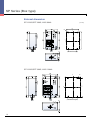
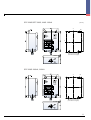
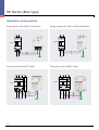
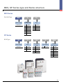
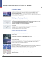
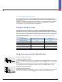
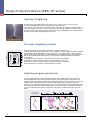
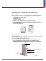
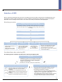
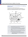
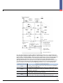
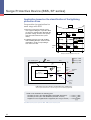
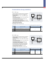
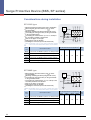
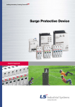
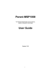
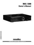
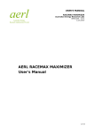
www.lsis.biz
Surge Protective Device
- BKS Series (Din rail type)
- SP Series (Box type Products)
BKS Series (Din-rail type Product)
SP Series (Box type Product)
The surge protective device is applied to the alternating current 50/60Hz,
220V/380V power system and provides the protection from the surge
overvoltage of an electric system.
If the protective device is normal, the display becomes green. The display
becomes red after operation (abnormal or after an accident).
SPD
Surge Protective Device
The surge protective device is applied
to the alternating current 50/60Hz,
220V/385V power system and provides
the protection from the surge
overvoltage of an electric
Contents
BKS Series (Din-rail type)
Product description
Product rating
External dimension
Installation wiring method
SP Series (Box type)
Product description
Product rating
External dimension
Installation wiring method
BKS, SP, Series type and Name structure
Technical Materials
04
04
05
05
06
06
08
12
13
14
BKS Series (Din-rail type)
Product description
The BKS surge protective device is applied to the alternating current 50/60Hz, 220V/380V power system and provides the
protection from the surge overvoltage of an electric system.
Moreover, it is the protection element (MOV) replacement type and is the product with convenience and economic efficiency.
However, only the protection module is provided so that separate components have to be combined according to the site
conditions.
If the protective device is normal, the display becomes green. The display becomes red after operation (abnormal or after an
accident).
Product rating
BKS-A
BKS-B
BKS-C
Pole
BKS-D
BKS-E
BKS-G
BKS-M
460V
320V
275V
1, 2, 3, 4 Pole
Rated system voltage, Un AC
[V]
220V
Maximum continuous operating voltage, Uc AC
[V]
320V
Voltage protection level, Up [kV]
1.0kV
Maximum discharge current, Imax (8/20 )[kA, per mode]
10kA
220/380V
320V
1.2kV
20kA
320V
1.5kV
40kA
Response time, ns
420V
2.0kV
2.3kV
60kA
70kA
1.5kV
40kA
100kA
< 25 ns
Usable ambient temperature
-40 ~ +80
Usable frequency, Hz
50/60 Hz
Attachment type
DIN-rail attachment type
Operation status indication window
Normal operation: Green, Abnormal/After an accident: Red
Min. terminal connection
1 Phase and Neutral 2.5, Earth 4
Protection class
Class
Alarm Contact
No
Class
No
No
No
No
Yes
* The surge protective device starts to operate above the maximum continuous operating voltage Uc (MCOV).
Terminal part with the
wire fastened
Operation state display window
The MOV system unit
can be replaced.
DIN-rail mounting bed
MOV System unit
Common bar
4
2.5kV
Yes
External dimension
<BKS-G, M>
144 (1P: 36, 2P: 72, 3P: 108)
36
36
36
7.9
91
36
98.9
<BKS-A, C, E>
1P
2P
3P
4P
15.5
67.5
61
45.5
6.5
Panel cutting size
Installation wiring method
Single phase diagram
3 Phase 3 Line diagram
3 Phase 4 Line diagram
* A separate fuse can be installed depending on the side conditions. (The fuse should be purchased separately is not supplied by LS.)
5
SP Series (Box type)
Product description
The SP series surge protective device is applied to the alternating current 50/60Hz, 220V/380V power system and provides the
protection from the surge overvoltage of an electric system.
Moreover, the protection module, disconnectable device (fuse), and fastened power and ground wires are organized into the allin-one steel cabinet with convenient installation and stability.
If the protective device is normal, the display becomes green. The display becomes red after operation (abnormal or after an
accident).
Product rating
- Single phase 2W+G (SPL)
SPL-110S
SPL-220S
Pole
Rated system voltage, Un AC
Maximum continuous operating voltage, Uc AC
Voltage protection level, Up
2W+G
2W+G
[V]
110V/220V
220V
[V]
320V
320V
[kV]
1.5kV
Maximum discharge current, Imax (8/20 ) [kA, per mode]
1.5kV
20kA
40kA
Response time, ns
80kA
5 ns
Usable ambient temperature,
-40 ~ +70
Usable frequency, Hz
50/60 Hz
Attachment type
Screw attachment type
Operation status indication window
Normal operation : Green LED lighting, Abnormal/After an accident : Red lighting
Protection class
Class
Class
Protection mode
/ Class
L1-N, L1-G, N-G
Product rating
-Three phase 3W+G (SPT) AC 380V
SPT-380S
Pole
Rated system voltage, Un AC
Maximum continuous operating voltage, Uc AC
Voltage protection level, Up
3W+G
[V]
380V
[V]
320V
2.0kV
[kV]
Maximum discharge current, Imax (8/20 ) [kA, per mode]
40kA
80kA
Response time, ns
50/60 Hz
Attachment type
Protection class
Protection mode
6
160kA
-40 ~ +70
Usable ambient temperature,
Usable frequency, Hz
Operation status indication window
120kA
< 5 ns
Screw attachment type
Normal operation : Green LED lighting, Abnormal/After an accident : Red lighting
Class
/ Class
Class
L1-G, L2-G, L3-G
/ Class
/ Class
Product rating
-Three phase 3W+G (SPT) AC 440V
SPT-440S
Pole
3W+G
Rated system voltage, Un AC
Maximum continuous operating voltage, Uc AC
Voltage protection level, Up
[V]
440V
[V]
320V
[kV]
Maximum discharge current, Imax (8/20 ) [kA, per mode]
2.0kV
40kA
80kA
Response time, ns
120kA
160kA
< 5 ns
Usable ambient temperature,
-40 ~ +70
Usable frequency, Hz
50/60 Hz
Attachment type
Screw attachment type
Operation status indication window
Normal operation : Green LED lighting, Abnormal/After an accident : Red lighting
Protection class
Class
/ Class
Class
Protection mode
/ Class
/ Class
L1-G, L2-G, L3-G
Product rating
-Three phase 4W+G (SPY)
SPY-220S
Pole
Rated system voltage, Un AC
Maximum continuous operating voltage, Uc AC
Voltage protection level, Up
4W+G
[V]
220/380V
[V]
320V
2.0kV
[kV]
Maximum discharge current, Imax (8/20 ) [kA, per mode]
40kA
80kA
Response time, ns
Usable frequency, Hz
50/60 Hz
Attachment type
Protection class
Protection mode
160, 200, 240kA
-40 ~ +70
Usable ambient temperature,
Operation status indication window
120kA
< 5 ns
Screw attachment type
Normal operation : Green LED lighting, Abnormal/After an accident : Red lighting
Class
/ Class
Class
/ Class
/ Class
L1-N, L2-N, L3-N, N-G
7
SP Series (Box type)
External dimension
[Unit: mm]
SPL-110S Type 20kA
C
L M4
77
C
L
(Panel dimension diagram)
SPL-220S Type 40kA
C
L
100.4
M4
C
L
40
(Panel dimension diagram)
8
[Unit: mm]
SPL-220S 80kA
C
L
127
M4
C
L
80
(Panel dimension diagram)
SPY-220S/SPT-380S, 440S 40kA
73
M4
150
CL
CL
73
(Panel dimension diagram)
9
SP Series (Box type)
External dimension
[Unit: mm]
SPY-220S/SPT-380S, 440S 80kA
130
CL
190
M4
CL
90
(Panel dimension diagram)
SPY-220S/SPT-380S, 440S 120kA
CL
100
(Panel dimension diagram)
10
M4
210
CL
[Unit: mm]
SPY-220S/SPT-380S, 440S 160kA
M4
210
CL
CL
100
(Panel dimension diagram)
SPY-220S 200kA, 240kA
M4
210
CL
CL
100
(Panel dimension diagram)
11
SP Series (Box type)
Installation wiring method
Single phase 2W+G(SPL-110S 20kA)
Breaker
Breaker
Ground
Load
Three phase 3W+G(SPT Type)
Ground
Load
Three phase 4W+G(SPY Type)
Breaker
Breaker
Load
12
Single phase 2W+G(SPL-220S 40kA/80kA)
Ground
Load
Ground
BKS, SP Series type and Name structure
BKS Series
Din-Rail Type
BKS
A
1P
Series category
Maximum
discharge current
Poles
Basic type
A
10kA
1P
1 Pole
B
20kA
2P
2 Pole
C
40kA
3P
3 Pole
D
60kA
4P
4 Pole
E
100kA
G
40kA
M
100kA
SP Series
BOX Type
SP
L
110
S
20kA
Series category
Poles
Rated system
voltage
Type category
Maximum
discharge current
Basic type
2W+G
110 AC 110/220V
T
3W+G
220
Y
4W+G
380
440
L
S
Basic type
20
20kA
AC 220V
40
40kA
AC 380V
80
80kA
AC 440V
120
120kA
160
160kA
200
200kA
240
240kA
13
Surge Protective Device (BKS, SP series)
Concept of surge
According to the definition of IEC, surge is delivered along the line or circuit and is the transient wave
form of the electric current, voltage, or power with rapidly increasing and gradually decreasing
characteristics. (IEC IEV 161-02-01)
If it is rainy with flashing lightning, the accident of the dead Internet or phone often occurs.
Moreover, when the light or electric machine switch is turned on, the audio sound is distorted or the
TV screen is fuzzy. It is caused by surge.
Main types of power problems
Surges, swells, and short-term overvoltage
Occurring during lightning and when turning on or off the system power line, turning on or off the
load, and operating the device
The voltage with the Rated system voltage exceeding 150% is called surge.
Breakage or degradation of an electronic part (equipment)
Transients
Transient is similar to surge but momentarily occurs only in the 1~2 sine wave form.
Impossible to process large data with equipment damaged
The positive impulse transient is also called spike.
Causes of surge occurrence
1. Surge caused by natural phenomena
Direct strike
Lightning directly strikes the structure, equipment, and power line, and the voltage with about 20kv
or higher and the overcurrent with several kA~300kA or higher occurs.
Indirect lightning
It strikes the power transmission and communication line, and surge is transmitted through the line.
It occurs the most frequently and has the very large energy with 6,000V or higher so that the
damage caused by it is the most frequent and the most.
Inducement lightning
Surge occurs due to the surge caused by the ground potential rapidly increased by the inflow of the
high voltage and high current induced through the conductor such as the power line,
communication line, and metal pipe buried in the land near the lightning point.
Bound change
Bound Change
between Clouds
Bound Change
Lightning
14
The charge induced with the bound change between the ground surface and a cloud, inside a
cloud, and between clouds flows into the power line, metal body, or ground surface so that
equipment is damaged.
2. Switching and starting surge
The switching surge with the maximum 6,000V when the substation switches the high voltage
power supply line and with the maximum 3,000V when the main switch of the distribution cabinet is
operated can flow in.
Furthermore, the maximum voltage impulse with 3,000V occurs when operating heavy equipment.
The impulse with 400~1,000V and the noise when using the arc welding device, compressor,
vacuum cleaner, or office machine nearby occur additionally.
Damage caused by surge
Nowadays, The damage caused by surge is rapidly increased by building intelligent buildings,
expanding the introduction of various control systems, and introducing the ubiquitous environment.
There has been no correct research on the damage caused by surge in the nation so far. However,
in the United States, it is estimated that the damage of time and expenses due to the occurrence of
failure of the electronic system caused by the high voltage and overcurrent reaches 26 billion USD
only in the industry every year.
As shown in the following table, 88.3% of unknown failures in case of electronic equipment are
caused by surge.
Power disturbance
Monthly average occurrence times
Percentage (%)
Oscillatory transients
62.2
48.8
Voltage spike
50.7
39.5
Under voltage
14.4
11.2
Over voltage
00.0
0.00
Blackout
0.06
0.05
Total
127.9
100
Transaction on Power Apparatus and system July-August. 1974 issue 1974 IEEE (Institute of Electrical and Electronic Engineers)
Surge test wave form (IEC Specification)
Surge voltage wave form
1.2/50 Surge voltage wave form
In case of the voltage wave form, it takes 1.2 (IEC 60-1) for the induced impulse to go up from the
start to the 10~90% of the maximum value induced at that time and 50 for it to reach the 50%(IEC
469-1).
The elevation time of the voltage wave form is short in comparison with that of the current wave
form, but the sustenance time continues more than two times in comparison with the current.
Surge current wave form
8/20 Surge current wave form
In case of the current wave form, it takes 8 to reach the 90% of the maximum current value (1pk)
in the 10% of the elevation curve and 20 to go down to the 50% of the descending curve.
15
Surge Protective Device (BKS, SP series)
Overview of lightning
The phenomenon of lightning that is the major source of surge occurrence is the source of
occurrence damaging the state-of-the-art equipment and human life.
If the direct strike comes into the information system equipment, the equipment and human life
cannot be protected. Therefore, as for the measure for the damage caused by the direct strike, the
proper protection region should be protected first with the selected lightning rod, and SPD should
be used to prevent the facility damage in the system.
Air temperature
Height
Principle of lightning creation
The thundercloud is the long vertical cloud and is 12,000m or higher in the
summer. The representative explanation of the mechanism of charge separation and accumulation
achieved within the thundercloud is as follows. There is a strong elevation air current within the
thundercloud, and the large pellets of hail collide with tiny ice particles within it. The large pellets of
hail are charged with the positive electricity and are transported upward with the elevation air
current effect.
Accordingly, the positive charge is accumulated in the upper side within the
thundercloud, and the negative charge is accumulated in the lower side.
Furthermore, the positive charge called the pocket charge occurring from
another mechanism is partially accumulated in the lower side.
Lightning progress mechanism
As for the lightning advanced by the downward leader with negative polarity, the preparatory
insulation destruction occurs from the pocket positive charge existing in the lowest part of the
negative charge cloud and the thundercloud, and the step leader is created in the lower end of the
thundercloud accordingly and moves toward the land with the repetitive advancement and
suspension. If the upward streamer charge occurs from the land when the step leader approaches
the land closely and meets the downward leader, the return stroke goes toward the thundercloud
for a lot of charge from the land to neutralize the charge of the conductive passage of the step
leader.
The lower part of
the thundercloud
16
Surge inflow path
The paths through which the lightning surge flows finally into the electrical and electronic
equipment according to the lightning charge phenomenon are classified into three types.
Direct strike
Lightning rod
Power line
Electrical
communication
facility
Signal and
communication lines
SPD for power
Electrical
communication
facility
SPD for
communication
Land
Ground
Direct strike
It is the phenomenon that lightning directly falls on the lightning rod, building structure, power line,
antenna, and pipe.
The whole lightning charge energy flows in so that the great destruction is accompanied.
Generally, the electrical device or electronic equipment is damaged near the progress path of the
thunderstroke current, and there is a high risk of fire.
There is a rare possibility that the direct strike directly falls on the inside facility of the building with
the external lightning protection facility such as lightning rod, but the part of a lightning rod (about
15% IEC 61643-12) can be classified as the power line or ground line. Likewise, the class I SPD
should be installed in the power facility point (the distribution panel and main power panel bonded
with the main ground terminal) through which the part of the direct stroke might flow.
Indirect lightning
It is the case of occurrence of the direct strike in the region a bit distant from a building, the part of
the lightning charge energy indirectly flows into the facility through the external drop wire and
through the ground system. Therefore, the class II or III SPD should be installed in preparation for
the indirect lightning surge flowing from the outside even in the closed environment that doesn t
need the external lightning protection system such as a lightning rod.
Induced lightning
It is the phenomenon occurring due to the strong electromagnetic wave induced when lightning
strikes the lightning rod of a building or falls on the tree or surface of a ground building or when the
charge between thunderclouds occurs in the near distance. It may occur in the trunk power line or
in the intermediate point of communication and signal lines. In the branch point of the line 20m far
from with the vertical wiring distance from the point inside he building with the class I SPD installed,
the class II (Ex. distribution panel) or III (Ex. single load control panel and household distribution
panel) SPD should be installed to prevent the inducement lightning.
17
Surge Protective Device (BKS, SP series)
Damages due to surge
Weakening of the withstand voltage
Applying the Small, Light, and Multi-Function IC: The devices damaged by surge due to the
increase of various 100V or lower information and communication devices, the number of the
devices damaged by surge is gradually increasing.
Increase of the damage due to the network of a facility system
Occurrence of the surge inside the building due to the increase of network facilities in most of
buildings damage all the equipment connected to the network.
Increase of the devices with surge or noise occurrence
- Rapid increase of the switching power change devices
- Increase of inducement load
- Charge and discharge of the DC load
Increase of lightning occurrence
As the number of thunderstorm days is increasing (11days=the average IKL for 20 years and 31
days for recent 4 years) due to the recent abnormal changes of weather and the subtropical
climate is widespread in the nation, lightning will increase more, and the size of thunderstroke
current will increase
Increase of damages
Damages due to the fire, breakage, malfunction, resetting of an unmanned facility, and increase of
the product manufacturing defect rate (semiconductor parts) are increasing.
Burn-out of the electric devices due to surge
18
What is SPD (Surge Protective Device)?
SPD is the device protecting various types of equipment from surge.
SPD is the device attenuating the overvoltage and noise and is called SPD or TVSS (Transient
Voltage Surge Suppressor). Specialists in the industry call it SPD. The terms such as SPD and
TVSS are used interchangeably.
SPD is the equipment designed to attenuate the dangerous overvoltage at the very short moment
appearing in the power line or telephone line, data network, CCTV circuit, cable TV circuit, and the
power line and control line connected to the electronic equipment.
Tek stop: Single Seq 10ks/s
Tek stop: Single Seq 10ks/s
1
1
Ch1 500mV~BW
M 5ms ch1
490mV
Ch1 500mV~BW
Wave form of Surge formation
M 5ms ch1
490mV
Wave form of Surge isolation
Ex.) Blocking the general surge of SPD
Operating principle of SPD
The purpose of installing SPD (Surge Protective Device) is that when the surge current comes into
the system due to any reasons, it is devised to have the current flow through itself instead of
flowing through the load so that the abrupt elevation of the voltage drop occurring from the load is
blocked to protect the load.
When the surge comes into the system, it can be achieved by letting the surge current flow through
the passage (SPD) with low impedance.
MOV is the part with very large impedance in the normal state.
With the voltage surge, the impedance of MOV is greatly reduced, and it becomes the passage
with low impedance having the surge flow through another passage that is not the load.
The flow of a huge voltage through SPD doesn t make voltage go up sharply.
6000V, 200A
400V
Restricting Voltage Level
L
Residual voltage flows
through the load.
SPD makes the
momentary overvoltage
return to L-N.
SPD
Load
N
G
The conceptual diagram of the surge restriction of SPD
19
Surge Protective Device (BKS, SP series)
MOV is the most reliable technology out of the technologies attenuating the surge voltage. The
clamping characteristics of MOV are reliable so that 96% or more SPD for power is selecting MOV.
SAD (Silicon Avalanche Diode) is often used as the SPD for the data line or communication line.
Major features of MOV are as follows.
It is devised to have the current rarely flow in the normal voltage.
It is devised to have the current flow a lot in the high voltage.
The voltage drop doesn t go up even though a lot of current flows.
Voltage
"MOV On"
"MOV Off"
Current
Voltage and current characteristics curve of SPD m
380V
220V
R
;8,
T
R S T
R S T
R S T N
220V
(Single phase) (Single phase) (3 Phase 3 wire) (3 Phase 4 wire)
* The applied voltage is 380V between phases, but as SPD sets the ground, it becomes 220V based on the ground potential. SPD should be
selected and installed in consideration of Maximum continuous operating voltage (MCOV) and the voltage protection level (Up).
20
Protection of power facilities
1st Protection
The surge penetrating from the outside is restricted by installing the surge protector on the
ACB 2nd side of the low voltage distribution panel.
2nd Protection
The surge protector is installed in the distribution board of each building or in the input
terminal of UPS or AVR to restrict the residual surge and the surge occurring internally.
3rd Protection
The surge protector is installed in the power input terminal of precision control equipment to
minimize the damage to the load.
Applying APD on the basis of facility configuration
Distribution
panel
Incoming panel
Distribution board for office
Distribution board for facilities
IS Room
Communication
antenna
For power
For data and
communication
Cooler
Cooling tower
* BKS-A/C/E products are used for power.
21
Surge Protective Device (BKS, SP series)
Types of Surge Protective Devices
Surge protective devices are classified into the voltage switching type and the voltage
restricting type depending on the features.
Voltage switching type SPD
1) Features of the discharge type SPD
If the surge exceeding the discharge start voltage of SPD comes in, the discharge momentarily
occurs for 1 cycle to 2 cycles, and it is in the short circuit during discharge so that the rapid
current flows through SPD with the momentary voltage drop accompanied.
2) Configuration of elements
Discharge elements such as gas tube elements and air gap elements are used for the discharge
type SPD.
3) Operating principle
It is in the open state below the discharge start voltage and is in the conduction state of the
momentary short circuit for the voltage exceeding the discharge start voltage. The conduction
state continues for about 2 cycles at maximum, and it automatically returns to the open state if
the surge is removed.
Voltage clamping type SPD
1) Features of the voltage clamping type SPD
The voltage restricting type SPD is the type limiting the voltage only to the specific level
differently from the discharge type. The limiting voltage is called clamping voltage or
suppression voltage, and the restricting voltage is determined by the correlation between the
line impedance and the lightning rod impedance.
2) Configuration of elements
MOV (Metal Oxide Varistor), semiconductor diodes, and sidactors with the nonlinear voltage
and current characteristics are used as elements.
3) Operating principle
It has the very low impedance for the voltage exceeding the operating voltage and the very high
impedance below the operating voltage so that the voltage is restricted for operation by the
correlation between the line impedance and the Surge Protective Device (SPD) impedance.
22
Surge protective devices are classified into the box type and the Din-rail type.
Box type SPD
The box type SPD is the all-in-one product configured with the steel incoming box including the
disconnectable device and the maintenance function option circuit with protection modules.
It is possible to selectively add the following optional functions needed for maintenance.
- Embedded degradation diagnosis function
- Embedded surge counter
- Noise filter
- Remote state transmission function
It is possible to select the protection mode and manufacture the large SPD.
The safe environment is provided with the all-in-one structure of all components during the
operation and maintenance.
It is possible to configure with the protection module, disconnectable device (fuse), and
maintenance function (option).
Din-rail type SPD
Din-rail type SPD is the protection element replacement type product manufactured as the plug-in
type with the protection
element inserted into the inflammable resin case.
It consists of individual protection module combination.
It is the plug-in type with the replacement for each protection element possible.
The convenient maintenance environment is provided by providing the mechanical contact.
It is the convenient protection element replacement type. Only the basic options
(protection modules) are provided so that separate components have to be combined
suitably to the site conditions during installation.
Terminal part with the wire fastened
Operation state display window
MOV system unit
Common bar
DIN Rail mounting
bed
The MOV system unit
can be replaced.
23
Surge Protective Device (BKS, SP series)
Characteristics for Each Application Element of SPD
Metal Oxide Varistor (MOV)
MOV has the property with the resistance value remarkably changing depending on the voltage.
The insulation state (high impedance) is maintained up to the insulation destruction voltage set in
the normal state, but if the surge voltage exceeding the maximum permitted voltage comes in,
impedance is degraded so that the path through which the surge current flows is provided.
Voltage
[A]
Small
current
region
Medium
current
region
Large
current
region
Current [A]
V-1 Characteristics of the Metal Oxide Varistor (MOV)
Operating characteristics of MOV
24
MOV equivalent circuit
Gas gap
It is various up to 1,000V. The discharge withstand current rating is high so that it may be
needed to have the surge current with up to 300,000A flow.
It has the characteristics of slow response speed and dynamic current so that it is used for a
special case now.
It has the advantages that it is operated with the discharge voltage permitted and that there is
little leaked current during the normal time so that it is used in combination with another
element if the high speed information processing is needed in the communication system.
Glow discharge area
Current
[A]
Unstable area
Arc discharge area
Voltage [A]
V-1 Characteristics of the discharge tube
Operating characteristics of the discharge tube
25
Surge Protective Device (BKS, SP series)
Characteristics for each application element of SPD
Silicon Restriction Element
Zener diode => tunnel effect
Avalanche diode => electronic breakdown effect
Response Speed: Very fast (0.001~0.01 ) compared with another element
Features: The operating voltage is low, and the voltage of several Vs can be restricted.
Application: It is a kind of Zener diodes, and the TVS (Transient Voltage Suppressor) element
increasing the surge withstand rating is usually used.
Off state
Operating curve
On state
V-1 Characteristics of the silicon restriction element
Operating characteristics of the silicon restriction element
26
Response characteristics for each
application element of SPD
Surge current wave form
Response of the voltage restricting type SPD
Response of the voltage switching type SPD
Response of the 1 port compound type SPD
Response of the 2 port compound type SPD
Response of the 2 port voltage switching type SPD
with the embedded
27
Surge Protective Device (BKS, SP series)
SPD Terms
Surge Protective Device (SPD)
It is the device to limit the temporary overvoltage and the
switching of the surge current. The device contains at least
one nonlinear part.
Impulse current (Iimp)
It is the current peak value (I peak) and charge (Q) tested
according to the test sequence of the operating test and is
used for class I SPD classification.
Continuous operating current (Ic)
It is the current flowing through each protection mode of SPD
when the maximum continuous operating current 0 is applied
to each mode.
Combination wave
It is generated in the generation device applying the 1.25/50
voltage impulse crossing the open circuit and the 8/20 current
impulse in the short circuit. The voltage, current amplitude,
and wave form delivered to SPD are defined with the
generation device and with the impedance of SPD selecting
surge.
Maximum continuous operating voltage (Uc, MCOV)
It is equivalent to the maximum effective value or the direct current
voltage and Rated system voltage steadily applied to the
protection mode of SPD.
Voltage protection level (Up)
It is the parameter representing the performance
characteristics of SPD limiting the terminal crossing voltage
selected in the preferred value list. The value is greater than
the highest value of the measured limiting voltage.
Measured limiting voltage
It is the maximum size of the voltage measured by crossing the
SPD terminal when the impulse with the specific wave form and
amplitude is applied.
Residual voltage (Ures)
It is the peak value of the voltage appearing between SPD
terminals due to the passage of the discharge current.
Temporary overvoltage (Ut)
It is the maximum effective value or direct current voltage at
which the protection device can withstand the voltage and
which exceeds the Maximum continuous operating voltage
(Uc).
Temporary overvoltage of the network (Utov)
The power frequency overvoltage, TOV, generated in the network in
the specific position relatively for a long time is generated due to the
internal defect of the LV system (Utov) or HV system (Utov).
Nominal discharge current (In)
It is the crest value of the current through SPD with the 8/20
current wave form.
It is used for class II SPD classification, class I and II test, and
prior control of SPD.
28
8/20 current impulse
It is the current impulse with the 8 virtual wave front time and
the 20 half value reaching time.
1.2/50 voltage impulse
It is the voltage impulse with the 1.2 virtual wave front time
(the elevation time from 10% of the peak value to 90%) and
with the 50 half value reaching time.
Thermal runaway
It is the operating condition inducing the accumulated
elevation and exceeding the dissipation capacity of the
container and access at the temperature at which the supply
power dissipation of SPD leads to the malfunction of the
internal element.
Thermal stability
If the SPD temperature is decreased as voltage is increased at
the conditions of specific Maximum continuous operating
voltage and of specific temperature conditions after the
operating test increasing the temperature, SPD is stable to the
heat.
SPD disconnector
It is the device blocking the SPD in the system in case of SPD
malfunction.
It is installed to prevent the steady malfunction occurring in the
system and visibly make an order for the SPD malfunction.
Selection of SPD
SPD is selected by analyzing the risk level of the overvoltage and overcurrent due to the power line, thunder discharge, and
ground power elevation and by considering the economic conditions. SPD with proper performance is selected through the
sequential review according to the flow chart on the selection procedure presented in the following diagram.
Selection procedure
Maximum continuous operating voltage of SPD
Temporary overvoltage, rated system current, and maximum current
The Maximum continuous operating voltage and temporary overvoltage of
SPD should be higher than the maximum operating voltage and temporary
overvoltage.
Protection distance (Installation place of SPD)
Forecasted lifetime of the failure mode
Relationship between SPD and another device
Selection of the voltage
protection level
Surge rating of the device to
be protected
SPD used in the nominal
voltage line of the system
Normal state
Does the leaked current
affect the human body?
Does it break down
another device?
Failure state
Surge protection cooperation between SPD
and the overcurrent protection device
Does the overvoltage protection device
operate in the rated system current?
Is it permitted for the overcurrent
protection device operate in the maximum
current without failure?
Does SPD affect
another element such
as a circuit
disconnecting device?
Considerations when selecting SPD
The following matters should be considered when selecting and applying SPD.
Normal state
1. Installed in the location as close as possible from the facility to
be protected Installed as closely as possible from the device or
disconnector. The length of the conductor contacting SPD
should be as short as possible.
2. Should be close to the SPD or device in the facility entrance.
Selection of the class based on the SPD installation place
Class : The place with the serious thunderstroke damage
where the thunderstroke current is partially
dissipated
Class : Installing the low voltage distribution panel and
industrial distribution board with light thunderstroke
damage
Class : Installing the in-house plug socket and household
distribution board with light thunderstroke damage
Selection of each SPD type
The box-type SPD or Din-rail SPD should be selected in
consideration of the characteristics of the device to be
protected and of maintenance conditions.
Box-type SPD: It is the all-in-one type with the protection
element, surge fuse, receiving box, and additional functions.
Maintenance cost is high, but it is relatively safe.
Din-rail SPD: The protection element, surge fuse, receiving
box, and additional functions should be combined. It is
possible to selectively replace the protection element.
29
Surge Protective Device (BKS, SP series)
Application based on the classification of the lightning
protection Zone
Classification of the lightning protection zone
The lightning protection zone (LPZ) should be spatially categorized, and the measure
corresponding to the equipment history inside the individual space should be taken. The level of
thunder threat to the structure defined in KSC IEC 62305-1 is represented by categorizing it into
the external area such as LPZ0 and the internal areas such as LPZ 1, 2,..n. * KSC IEC62305-4
LPZD
Antenna
Mast or rail
Power line
Boundary of
LPZ 2
LPZ 2
LPZ 1
Boundary of
LPZ 1
Equipment
Water
pipe
Connection
location
Communication line
Accessing the service facility directly or with the proper SPD
LPZ 0A Area: It is the region with the threat of the thunder by the direct strike and of the
lightning electromagnetic field. The whole or part of the thunder surge
current tends to flow through the internal system.
LPZ 0B Area: It is protected from the thunderstroke by the direct stroke of the lightning rod
but is the region with the threat of the whole lightning electromagnetic field.
The part of the lightning surge current tends to flow through the internal
system.
LPZ 1 Area: It is the region where the surge current is limited by the current classification in
the boundary area or by the class I SPD. Space blocking is used to weaken
the electromagnetic field caused by the thunderstroke.
LPZ 2,...,n Areas: They are the regions where the surge current is limited more by the
current classification by the class ii or III SPD of the boundary area.
Additional space blocking is used to weaken the generation of the
electromagnetic field further.
30
Penthouse metal part
Penthouse
equipment
Shielding net
Shielding
cabinet
Camera
Bonding
terminal
Metal front part
Ferroconcrete
Ground
Ferroconcrete
Sensitive electronic
equipment
External metal facility
Communication line
Expanded
LPZ OA
Low voltage power line
High voltage Power line
Parking lot
Metal cable Pipe
(Expanded LPZ OA)
Basic ground electrode
The area with the different strength of LEMP, the lightning prevention area, is determined for the
electromagnetic field generated by LEMP not to have the failure occur in the facility or electronic or
electrical device inside the building, and the potential is equalized by correctly connecting the metal
thing, power line, communication line, and water pipe with the common ground in the boundary
part of the lightning prevention area not to have the abnormal voltage generated inside the
lightning prevention area. The separation of the external area (LPZ 0) from the internal area (LPZ
1) is clear, but the separation of the other lightning prevention areas is not clearly specified. The
specific examples of the facilities inside the lightning prevention area are in the following table.
Lightning prevention area
LPZ 0A
LPZ 0B
LPZ 1
LPZ 2
Examples of specific target facilities
Facilities outside the lightning rod protection range except for the outside lights
(street lights and security lights).
Facilities inside the lightning rod protection range out of outside facilities such
as penthouse receiving (cubicle) facility, air conditioning outside device, airline
failure light, and antenna.
Facilities in the Inlet Part inside the Building: Receiving and transforming
facilities, MDF, and weak electricity terminal box.
Individual shielding area inside the building such as trunk line distribution board,
common facility control panel, IS room, and disaster prevention room.
Note) LEMP: It is the thunder electromagnetic pulse. Out of the electromagnetic pulses (EMP), LEMP is the one caused by lightning, and NEMP is
the one caused by nuclear explosion.
31
Surge Protective Device (BKS, SP series)
Application based on the classification of the lightning
protection Zone
Cooperation for protection for
each stage with SPD
LPZ OA
1) Measure to protect the internal system
from surge Installing the cooperative SPD
for all power and signal line (SPD with the
protection voltage, location, and capacity
well selected to minimize the system
failure)
LPZ OB
LPZ 1
LPZ 2
SPD II
2) Lightning protection zone with multiple
LPZs Installing SPD (Ex.: SPD I in LPZ1
and SPD II in LPZ2) corresponding to
each LPZ to the inlet
SPD III
Power
line
SPD I
ACB-Pannel
SPD II
LPZ 3
SPD III
L/P-Pannel
Plug socket
Example of the SPD application of the power
ClassⅠ SPD
LPS + Shielding LPZ 1
ClassⅡ SPD
LPZ 0
ClassⅢ SPD
Shielding LPZ 2
Class Ⅱ
SPD 1/2
(SB)
Class Ⅰ
SPD 0/1
(MB)
Distribution
panel
Device
(damaged object)
Housing
Lighting
stroke
current
LPMS using the protection of the SPD cooperative with the space shielding object
-The device protected well from the conductive surge and from the radiating magnetic field-
1. SPD can be installed in the following point.
- Boundary of LPZ 1 (Ex.: Main distribution panel MB / ACB-Panel)
----> Class
- Boundary of LPZ 2 (Ex.: 2nd distribution panel SB / P-Panel)
----> Class
- Equipment or the neighborhood of equipment (Ex.: Plug socket SA) ----> Class
Note) LPMS means the protection system for LEMP. * LEMP protection measures system
32
SPD
SPD
SPD
Class Ⅰ SPD
Class Ⅱ SPD
Heavy
load
device
Class Ⅲ SPD
Light
load
device
Facility
Substation
Distribution panel
main distribution
board
Distribution
Workstation
Note) If the heavy load device or light load device is 20m or farther from the SPD installation position in the unshielded vertical wiring distance, the
additional protection should be considered.
Model recommended for application
SPL-110S 20kA
SPL-220S 40kA
SPL-220S 80kA
SPY-220S 40kA
SPY-220S 80kA
SPT-380S 40kA
SPT-440S 40kA
SPT-380S 80kA
SPY-220S 120kA
SPY-220S 160kA
SPY-220S 200kA
SPY-220S 240kA
SPT-380S 120kA
SPT-380S 160kA
BKS-A
BKS-B
BKS-C
BKS-D
BKS-E
BKS-G
BKS-M
Standard to select the SPD for each LPZ
LPZ 1
- The class I SPD with the impulse current with Iimp 15kA ~ 60kA on the basis of the
10/350 wave form is applied.
LPZ 2
- The class II SPD with the maximum discharge current with Iimp 40kA ~ 160kA on the basis
of the 8/20 wave form is applied.
LPZ 3
- The class III SPD on the basis of the 1.2/50
applied.
and 8/20
combination wave form is
33
Surge Protective Device (BKS, SP series)
Considerations during installation
SPD shows the difference in performance depending on the installation
method.
Therefore, SPD is installed in consideration of the following matters.
1) Protection and installation method
If SPD with sufficient surge rating is installed in the location close to the entrance of the distribution board
for various wiring systems when the device or facility to be protected has sufficient overvoltage rating, most
facilities can be protected.
2) Shuttle vibration phenomenon
If the device or facility to be protected is distant from SPD, the voltage that is about 2 times higher than the
SPD limiting voltage is generated in the facility to be protected by the shuttle vibration of the incidence
surge. The shuttle vibration of surge can be disregarded in case of the 10m or shorter wiring length, but the
twofold or higher voltage can be generated in case of the 10m or shorter length so that the cooperation
between the protection element inside the device or facility to be protected and SPD should be well
accomplished.
3) Length of the connection line
In order to most effectively protect the overvoltage, it is necessary to shorten the length of the connection
line for SPD wiring and to apply the wiring method restricting the induced voltage of the inductance of the
connection line.
4) Necessity for additional protection
If the lightning surge voltage flowing into the device or facility to be protected is comparatively low, the
protection effect is sufficient with the SPD installed in the building entrance. However, if the
electromagnetic field is generated inside the building due to the lightning discharge and the very precise
and sensitive facility such as computer or the facility to be protected is far from the SPD installed in the
entrance, the additional protection device needs to be installed.
5) Selection of the SPD installation place based on the class test
It is very important to select the SPD with a suitable specification in consideration of the overvoltage
generated in the lightning surge voltage or low voltage wiring system.
6) Concept of the protection area
Regarding the design or application of the proper surge protection, it is the most desirable that the
protection area is classified into layers on the basis of the concept of protection area prescribed in IEC and
that in case of installing SPD by segmenting the wiring system, SPD is installed in the boundary of the
protection area.
34
Considerations during installation
SPL-110S type
Disconnecting the breaker power before installation
Measuring the ground resistance (10 or lower
recommended)
Mounting and fixing the SPL-110 series (using the
M4 screw)
Connecting the wire (green line) on the ground side
to the ground booth bar
Connecting the residual wires (L and N) to the
secondary terminal of the breaker
Connecting the L line (black line) to the secondary
110V L phase terminal of the breaker
Connecting the N line (white line) to the secondary N
phase terminal of the breaker
Putting power into the breaker
Checking the LED state (Power On)
LS
SPD
Breaker
Black
White
Green
Load
Caution: The SPD wire is cut very shortly to maintain the mounting location and the shortest distance with the breaker connection terminal.
Recommended wire size used (Unit: mm2)
Wire
color
20kA
Wire
type
4
HKIV
Connection location
Black
Connected to the MCCB R phase secondary terminal
White
Connected to the MCCB neutral secondary terminal
Green
Connected the grounding bar
The wire used should be purchased separately.
SPL-220S type
Disconnecting the breaker power before installation
Measuring the ground resistance (10 or lower
recommended)
Mounting and fixing the SPL-220S series (using the
M4 screw)
Connecting the wire (green line) on the ground side
to the ground booth bar
Connecting the residual wires (L and N) to the
secondary terminal of the breaker
Connecting the L line (black line) to the MCCB
secondary 220V L phase terminal of the breaker
Connecting the N line (white line) to the MCCB
secondary N phase terminal of the breaker
Putting power into the breaker
Checking the LED state (Power On/ Alarm Off)
LS
SPD
Breaker
Black
White
Green
Load
Caution: The SPD wire is cut very shortly to maintain the mounting location and the shortest distance with the breaker connection terminal.
Wire
color
Recommended wire size used (Unit: mm2)
40kA
80kA
Wire
type
4
6
HKIV
Connection location
Black
Connected to the MCCB R phase secondary terminal
White
Connected to the MCCB neutral secondary terminal
Green
Connected the grounding bar
The wire used should be purchased separately.
35
Surge Protective Device (BKS, SP series)
Considerations during installation
SPY-220S type
Disconnecting the breaker power before installation
Measuring the ground resistance (10 or lower
recommended)
Mounting and fixing the SPD (using the M4 screw)
Connecting the wire (green line) on the ground side
to the ground booth bar
Connecting the residual wires (L1, L2, L3, and N) to
the secondary terminal of the breaker
Refer to the figure on the right.
Putting power into the breaker
Checking the LED state (Power On/ Alarm Off)
LS
SPD
Breaker
Black
Red
Blue
Green
White
Load
Caution: The SPY-220S series are cut very shortly to maintain the mounting
location and the shortest distance with the breaker connection terminal.
Recommended wire size used (Unit: mm2)
Wire
color
40kA
80kA
120kA
160kA
Wire
type
6
10
10
10
HKIV
Connection location
Black
Connected to the MCCB L1 phase secondary terminal
Red
Connected to the MCCB L2 phase secondary terminal
Blue
Connected to the MCCB L3 phase secondary terminal
White
Connected to the MCCB neutral secondary terminal
Green
Connected the grounding bar
SPT-380S type
Measuring the ground resistance (10 or lower
recommended)
Mounting and fixing the SPD (using the M4 screw)
Connecting the wire (green line) on the ground side
to the ground booth bar
Connecting the residual wires (L1, L2, and L3) to the
secondary terminal of the breaker
Refer to the figure on the right.
Putting power into the breaker
Checking the LED state (Power On/ Alarm Off)
LS
SPD
Breaker
Black
Red
Green
Blue
Load
Caution: The SPT-380S series are cut very shortly to maintain the mounting
location and the shortest distance with the breaker connection terminal.
Wire
color
Black
40kA
80kA
120kA
160kA
Wire
type
6
10
10
10
HKIV
Connected to the MCCB L1 phase secondary terminal
Red
Connected to the MCCB L2 phase secondary terminal
Blue
Connected to the MCCB L3 phase secondary terminal
Green
36
Recommended wire size used (Unit: mm2)
Connection location
Connected the grounding bar
Caution during installation
Be sure to read the user manual and safety instructions before using the product.
Please deliver the user manual to the end user or person in charge of maintenance.
Caution for safety
Correctly use it after thoroughly reading the caution for safety and the danger before handling,
wiring, manipulation, repair, and checking. It is the important details on safety so that be sure to
observe them.
Danger: Infringing the instructions results in death or serious injury.
Caution: Infringing the instructions results in light injury or physical damage.
Danger
1. Be sure to turn off the upper breaker before installing the product. There is the danger of
electric shock during installation.
2. Be careful not to contact the open part of the terminal. It can cause the accident of electric
shock or short circuit.
3. Be sure not to make the part of the body contact the two exposed hot-lines at the same time. It
may cause the electric shock.
Caution
1. Be sure to read the caution before installing the product and install according to instructions.
2. There is the danger of malfunction or accident occurrence due to incorrect installation. The
qualified person (electric engineer) should install and repair the surge protective device.
3. Please avoid installation in the environment of rain, oil, dust, and direct light.
There is the danger of electric shock, leak, short circuit, fire, and malfunction.
1) Operating Temperature: -40~70℃
2) Relative Humidity: 45~85%
3) Altitude: 2000m or lower
4) There should be no abnormal vibration and shock, excessive vapor, oil, smoke, dust,
corrosive gas, and flammable gas.
4. Please connect it to the power with right Product rating. Improper rating causes malfunction or
failure.
5. As the insufficient fastening torque of a terminal causes overheat or fire, please refer to the
fastening torque specified in the user manual for each product to correctly fix the terminal.
* As for the details, refer to the mounting method for each device type.
6. Install the connection conductor and each phase in parallel when mounting a terminal. There is
the danger of the short circuit accident between phases.
7. The insulation resistance measurement and withstand voltage test between phases cannot be
performed. In case of doing the above test between the lines of the circuit, do it after detaching
the product from the circuit. It may cause a failure.
8. Be sure to ground the earth terminal of an electric device.
9. Electric shock or fire can occur.
10. Do not perform the unauthorized modification.
11. Please handle the disposal of products according to the Waste Management Law.
37
Memo
38
� For your safety, please read user's manual thoroughly before operating.
� Contact the nearest authorized service facility for examination, repair, or adjustment.
� Please contact a qualified service technician when you need maintenance.
Do not disassemble or repair by yourself!
Safety Instructions
� Any maintenance and inspection shall be performed by the personnel having expertise concerned.
ⓒ 2010.4 LSIS Co.,Ltd. All rights reserved.
� HEAD OFFICE
LS-ro 127 (Hogye-dong) dongan-gu Anyang-si
Gyeonggi-do Korea
Tel. (82-2)2034-4887, 4873, 4148
Fax. (82-2)2034-4648
www.lsis.biz
� Global Network
�LSIS (Middle East) FZE �
�Dubai, U.A.E.
Address: LOB 19 JAFZA VIEW TOWER Room 205, Jebel Ali Freezone P.O. Box 114216, Dubai, United Arab Emirates
Tel: 971-4-886 5360 Fax: 971-4-886-5361 e-mail: [email protected]
�Dalian LSIS Co., Ltd. �
�Dalian, China
Address: No.15, Liaohexi 3-Road, Economic and Technical Development zone, Dalian 116600, China
Tel: 86-411-8273-7777 Fax: 86-411-8730-7560 e-mail: [email protected]
�LSIS (Wuxi) Co., Ltd. �
�Wuxi, China
Address: 102-A , National High & New Tech Industrial Development Area, Wuxi, Jiangsu, 214028, P.R.China
Tel: 86-510-8534-6666 Fax: 86-510-522-4078 e-mail: [email protected]
� CHEONG-JU PLANT
Cheong-Ju Plant #1, Song Jung Dong, Hung Duk Ku,
Cheong Ju, 361-720, Korea
�LSIS-VINA Co., Ltd. �
�Hanoi, Vietnam
Address: Nguyen Khe - Dong Anh - Ha Noi - Viet Nam
Tel: 84-4-882-0222 Fax: 84-4-882-0220 e-mail: [email protected]
�LSIS-VINA Co., Ltd. �
�Hochiminh , Vietnam
Address: 41 Nguyen Thi Minh Khai Str. Yoco Bldg 4th Floor, Hochiminh City, Vietnam
Tel: 84-8-3822-7941 Fax: 84-8-3822-7942 e-mail: [email protected]
�LSIS Shanghai Office �
�Shanghai, China
Address: Room 32 floors of the Great Wall Building, No. 3000 North Zhongshan Road, Putuo District, Shanghai, China
Tel: 86-21-5237-9977 Fax: 89-21-5237-7189 e-mail: [email protected]
�LSIS Beijing Office �
�Beijing, China
Address: B-Tower 17FL.Beijing Global Trade Center B/D. No.36, BeiSanHuanDong-Lu, DongCheng-District,
Beijing 100013, P.R. China
Tel: 86-10-5825-6025,7 Fax: 86-10-5825-6026 e-mail: [email protected]
�LSIS Guangzhou Office �
�Guangzhou, China
Address: Room 1403, 14/F, New Poly Tower, No.2 Zhongshan Liu Road, Guangzhou 510180, P.R. China
Tel: 020-8326-6754 Fax: 020-8326-6287 e-mail: [email protected]
�LSIS Chengdu Office �
�Chengdu, China
Address: Room 1701 17Floor, huamin hanjun internationnal Building, No1 Fuxing Road Chengdu, 610016, P.R. China
Tel: 86-28-8670-3201 Fax: 86-28-8670-3203 e-mail: [email protected]
�LSIS Qingdao Office �
�Qingdao, China
Address: Room 2001,20/F,7B40, Galaxy Building, No.29 Shandong Road, Shinan District, Qingdao 266071, P.R. China
Tel: 86-532-8501-6058 Fax: 86-532-8501-6057 e-mail: [email protected]
�LSIS NETHERLANDS Co.Ltd �
�Schiphol-Rijk, Netherlands
Address: 1st. Floor, Tupolevlaan 48, 1119NZ,Schiphol-Rijk, The Netherlands
Tel: 31-20-654-1420 Fax: 31-20-654-1429 e-mail: [email protected]
Specifications in this catalog are subject to change without notice due to
continuous product development and improvement.
2012. 10
�LSIS Gurgaon Office �
�Gurgaon ,India
Address: 109 First Floor, Park Central, Sector-30, Gurgaon- 122 002, Haryana, India e-mail: [email protected]
Surge Protective Device(E) 2010. 04 /(03) 2012. 10 Printed in Korea STAFF