1
DMX setup
Notice:
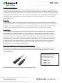
Be sure to follow the diagrams below when making your own cables. Do not connect the cables shield conductor to the ground lug or allow the shield conductor to come in contact with the XLRs outer casing. Grounding the shield could cause a short circuit and erratic behaviour.
Special note:
Line termination:
When longer runs of cable are used, you may need to use a terminator on the last unit to avoid erratic behaviour.
Using a cable terminator will decrease
the possibilities of erratic behaviour.
(3-pin - Order ref: CABL90, 5-pin - Order ref: CABL89)
Termination reduces signal transmission
problems and interference. It is always
advisable to connect a DMX terminal,
(resistance 120 Ohm 1/4 W) between pin 2
(DMX-) and pin 3 (DMX+) of the last fixture.
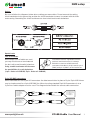
5-pin XLR DMX connectors:
Some manufactures use 5-pin XLR connectors for data transmission in place of 3-pin. 5-pin XLR fixtures
may be implemented in a 3-pin XLR DMX line. When inserting standard 5-pin XLR connectors in to a
3-pin line a cable adaptor must be used. The diagram below details the correct cable conversion.
5-pin XLR (socket)
Pin 1: GND (screen)
Pin 2: Signal (-)
Pin 3: Signal (+)
Pin 4: N/C
Pin 5: N/C
3-pin XLR (socket)
Pin 1: GND (screen)
Pin 2: Signal (-)
Pin 3: Signal (+)
3-pin XLR (socket)
Pin 1: GND (screen)
Pin 2: Signal (-)
Pin 3: Signal (+)
5-pin XLR (socket)
Pin 1: GND (screen)
Pin 2: Signal (-)
Pin 3: Signal (+)
Pin 4: N/C
Pin 5: N/C
www.prolight.co.uk
PF LED Profile User Manual
7