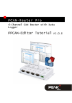
1
PCAN-Router
Universal CAN Converter
User Manual
PCAN-Router – User Manual
Products taken into account
Product Name
Model
Item Number
Ser. no.
PCAN-Router
2 D-Sub connectors,
additional digital input,
LPC2129, 2 kBit EEPROM
IPEH-002210
up to
00299
PCAN-Router
Screw terminal block,
additional serial interface,
LPC2129, 2 kBit EEPROM
IPEH-002210-P
up to
00299
PCAN-Router
2 D-Sub connectors,
additional digital input,
LPC2194/01, 256 kBit EEPROM
IPEH-002210
starting at
00300
PCAN-Router
Screw terminal block,
additional serial interface,
LPC2194/01, 256 kBit EEPROM
IPEH-002210-P
starting at
00300
Product names mentioned in this manual may be the trademarks or registered
trademarks of their respective companies. They are not explicitly marked by “™” and
“®”.
© 2008 PEAK-System Technik GmbH
PEAK-System Technik GmbH
Otto-Roehm-Strasse 69
64293 Darmstadt
Germany
Phone: +49 (0)6151-8173-20
Fax:
+49 (0)6151-8173-29
www.peak-system.com
[email protected]
Issued 2008-10-16
2
PCAN-Router – User Manual
Contents
1
1.1
1.2
1.3
2
2.1
2.2
2.3
2.4
2.5
Introduction
5
Properties at a Glance
Scope of Supply
Prerequisites for the Operation
5
6
6
Connectors and Coding Solder Bridges
7
D-Sub Connector
Screw Terminal Block
J4 Connector Panel: Serial Ports
J5 Connector Panel: JTAG Ports
Coding Solder Bridges
8
9
10
11
12
3
Port Assignment of the Microcontroller
13
4
Operation
16
5
Software
17
5.1 Installing the WinARM Package
5.1.1 Decompressing the ZIP Archive
5.1.2 Setting up Additional Search Paths
5.2 CAN Software Library
5.3 Demo Firmware
5.3.1 Compiling the Demo Firmware
17
17
18
20
20
20
6
22
Firmware Upload
6.1 Uploading Firmware via CAN
6.1.1 System Requirements
6.1.2 Preparing Hardware and Software
6.1.3 Uploading the Firmware
6.2 Uploading Firmware via the Serial Connections
3
22
22
22
25
28
PCAN-Router – User Manual
7
Frequently Asked Questions (FAQ)
30
8
Technical Specifications
31
Appendix A
A.1
Certificates
33
CE
Appendix B
33
Dimension Drawing
4
34
PCAN-Router – User Manual
1
Introduction
The PCAN-Router is a module with two CAN channels, the data
traffic of which is processed by a freely programmable microcontroller. This means that incoming CAN messages can be individually
evaluated, converted, and filtered in order to then send the adjusted
CAN messages to the respective other network.
You can copy any firmware you have developed yourself to the
PCAN-Router via the boot loader, which has already been implemented, by using CAN. The PCAN-Router is supplied with a demo
firmware which forwards CAN messages 1:1 between the two
channels at 500 kBit/s. The respective source code is included on the
supplied CD.
1.1
Properties at a Glance
Microcontroller with 16/32-Bit ARM CPU:
•
NXP (Philips) LPC2129 (up to ser. no. 00299)
•
NXP (Philips) LPC2194/01 (starting at ser. no. 00300)
EEPROM add-on memory:
•
2 kBit (up to ser. no. 00299)
•
256 kBit (starting at ser. no. 00300)
Import of a new firmware via CAN
Two High-speed CAN channels (ISO 11898-2), up to 1 MBit/s
One additional LIN channel on request
Status indication with two duo LEDs
5
PCAN-Router – User Manual
Connections via two 9-pin D-Sub connectors or a 10-pin screw
terminal block (Phoenix)
Additional digital input (applies for version with D-Sub
connectors only)
Additional serial RS-232 interface (only for version with screw
terminal block)
4-bit coding of the hardware by solder bridges
Aluminum profile housing with option of fitting on top hat rails
1.2
Scope of Supply
The scope of supply normally consists of the following parts:
PCAN-Router in aluminum profile housing
10-pin screw terminal block bar (IPEH-002210-P only)
CD with documentation, Windows software (C and C++ compiler
GNU WinARM, flash program), and demo project
1.3
Prerequisites for the Operation
The following prerequisites must be given, so that you can use the
PCAN-Router properly:
Power supply in the range of 7.5 to 26 V DC
To upload a new firmware via CAN you need:
•
CAN interface of the PCAN series for the computer (e.g.
PCAN-USB)
•
Windows 2000 SP4 / XP SP2 / Vista (32 Bit)
6
PCAN-Router – User Manual
2
Connectors and Coding
Solder Bridges
The PCAN-Router is supplied in two versions which differ in the
type of connections and the signals provided in addition to the CAN
channels:
with two 9-pin D-Sub connectors, additional digital input (IPEH002210)
with a 10-pin screw terminal block, additional serial interface
(IPEH-002210-P)
For direct access to the serial and debugging ports of the
microcontroller, additional – yet not equipped – connector panels
are available on the PCAN-Router’s board.
Furthermore the board has four coding solder bridges in order to
assign a fixed status to the corresponding input bits of the
microcontroller.
The following subsections describe each connector assignment.
7
PCAN-Router – User Manual
2.1
D-Sub Connector
(IPEH-002210 only)
The D-Sub connectors are used for the CAN channels CAN1 and
CAN2.
The power supply can be provided via both connectors. The supply
connections +Ub1 and +Ub2 are connected internally in a reactionless
configuration. This means that different power sources can be
connected, if applicable.
The CAN1 connector also offers a pin to activate the bootloader
(Boot CAN1, see section 6.1 Uploading Firmware via CAN on page
22) and the CAN2 connector a digital input (Din0) which can be
interpreted by the microcontroller.
Figure 1: CAN1 and CAN2 D-Sub connector pins
Pin
Function connector
CAN1
Function connector
CAN2
1
Not used
Not used
2
CAN1_L
CAN2_L
3
GND
GND
4
Reserved (LIN)
Not used
5
SHIELD
SHIELD
6
Boot CAN1 (high-active) Not used
7
CAN1_H
8
Not used
CAN2_H
Din0 (low-active)
9
Supply +Ub1
(7.5 - 26 V DC)
Supply +Ub2
(7.5 - 26 V DC)
See also chapter 3 Port Assignment of the Microcontroller on page
13.
8
PCAN-Router – User Manual
2.2
Screw Terminal Block
(IPEH-002210-P only)
Apart from power supply and CAN channels, the screw terminal
block includes connections for a serial interface with RS-232 levels.
Figure 2: Screw terminal block connections
Terminal
Function
1
Supply +Ub
(7.5 - 26 V DC)
2
GND
3
CAN1_L
4
CAN1_H
5
CAN2_L
6
CAN2_H
7
Boot CAN1 (high-active)
8
Reserved (LIN)
9
RS-232 RxD
10
RS-232 TxD
See also chapter 3 Port Assignment of the Microcontroller on page
13.
9
PCAN-Router – User Manual
2.3
J4 Connector Panel: Serial Ports
The non-equipped connector panel J4 on the PCAN-Router’s board
provides an additional access option to the serial ports of the
LPC2129 or LPC2194/01 microcontroller (μC).
Figure 3: Distribution of pins in connection panel J4
Pin
Signal
Port μC
1
RxD0
P0.1
2
TxD0
P0.0
3
Not used
4
/Boot_ser
5
GND
6
+5.0 V
P0.14
The RxD0 and TxD0 signals are forwarded to a level converter for
the RS-232 standard. The PCAN-Router version with screw terminal
block provides access to the adjusted signals at terminals 9 (RS-232
RxD) and 10 (RS-232 TxD).
Attention! The RxD0 (pin 1) and TxD0 (pin 2) signals in
connector panel J4 are designed for TTL levels only. Using RS232 levels at these connections can cause damage to the PCANRouter’s electronics.
10
PCAN-Router – User Manual
2.4
J5 Connector Panel: JTAG Ports
The non-equipped connector panel J5 on the PCAN-Router’s board
provides an additional access option to the JTAG ports of the
LPC2129 or LPC2194/01 microcontroller (μC) for hardware
debugging.
Figure 4: Distribution of pins in connection panel J5
Pin
Signal
1
GND
Port μC
Internal wiring
2
GND
3
/Reset
4
3.3 V
/Reset
Pull-up
5
TCK
P1.29
Pull-down (R30)
6
TMS
P1.30
Pull-up
7
TDO
P1.27
Pull-up
8
TDI
P1.28
Pull-up
9
RTCK
P1.26
Pull-down (R31)
10
TRST
P1.31
Pull-up
If constant internal pull-down wiring of the TCK or RTCK signals is
not suitable for your purposes, you can remove the respective pulldown resistor on the PCAN-Router’s board by soldering it out. Both
resistors (each 10 kΩ) are located next to the J5 connector panel J5
(see figure).
Figure 5: Position of pull-down resistors next to the J5 connector panel
11
PCAN-Router – User Manual
2.5
Coding Solder Bridges
The four positions for coding solder bridges (ID 0 - 3) are each
assigned to one port of the microcontroller LPC 2129 or LPC2194/01
(μC):
Position
0
1
2
3
Port μC
P0.4
P0.5
P0.6
P0.7
Position is …
Status at the port
jumpered
Low
open
High
The status of the ports is relevant in the following cases:
The loaded firmware is programmed so that it reads the status
at the corresponding ports of the microcontroller. E.g. the
activation of certain functions of the firmware or the coding of
an ID is conceivable here.
When uploading a firmware via CAN, the PCAN-Router is
identified by a 4-bit ID which is determined by the solder
bridges. A bit is set (1), if the corresponding solder bridge
position is open (default setting: ID 15, all positions open).
Position
Binary digit
Decimal equivalent
0
1
2
3
0001
0010
0100
1000
1
2
4
8
See also section 6.1 Uploading Firmware via CAN on page 22.
12
PCAN-Router – User Manual
3
Port Assignment of the
Microcontroller
The following table lists the used inputs and outputs (ports) of the
LPC2129 and LPC2194/01 microcontroller (μC) and their function in
the PCAN-Router.
Active Function/connection 1
(μC)
Port
I/O
μC function
Signal
P0.0
O
TxD UART0
TxD0
Serial communication,
Transmit, J4:2 or STB:10 (RS232 levels)
P0.1
I
RxD UART0
RxD0
Serial communication,
Receive, J4:1 or STB:9 (RS-232
levels)
P0.2
I, O SCL
SCL
P0.3
I, O SDA
SDA
I2C bus to the EEPROM
Microchip 24LC02B or
Atmel AT24C256B 2
P0.4
I
Port pin
ID0
High
P0.5
I
Port pin
ID1
High
P0.6
I
Port pin
ID2
High
P0.7
I
Port pin
ID3
High
P0.8
O
TxD UART1
LIN_TxD
LIN Transmit 3
P0.9
I
RxD UART1
LIN_RxD
LIN Receive3
P0.10
O
Port pin
LIN_en
P0.12
O
Port pin
High
Coding solder bridges on
board (ID 0 - 3), jumpered =
Low
Enable LIN transceiver3
Reserved
1
CAN1/2:n Pin n of the respective D-Sub connector
STB:n
Terminal n on the screw terminal block
J4/5:n
Pin n of the respective connector panel on the board
2
PCAN-Router serial numbers starting at 00300
3
This function is available in the optional PCAN-Router version with LIN transceiver
only.
13
PCAN-Router – User Manual
4
Signal
Active Function/connection 1
(μC)
Port pin
/Boot_ser
Low
Activate flashing via serial
interface, J4:4
I
Port pin
/Boot_CAN
Low
Activate flashing via CAN 1
with 500 kBit/s, CAN1:9 and
STB:7 (due to wiring highactive)
P0.17
O
Port pin
V24_en
High
Deactivate the RS-232
converter by Low level
(activated by default);
possibility for energy saving
P0.19
I
Port pin
Switch
High
Digital input Din0, CAN2:8
(due to wiring low-active)
P0.21
O
Port pin
CAN_en_2
Low
P0.22
O
Port pin
CAN_en_1
Low
Activate the respective CAN
transceiver 4
P0.23
I
RD2
CAN2_RxD
CAN 2 Receive
P0.24
O
TD2
CAN2_TxD
CAN 2 Transmit
P0.25
I
RD1
CAN1_RxD
CAN 1 Receive
TD1
O
TD1
CAN1_TxD
CAN 1 Transmit
P0.27
I
Analog input
V-Power2
Measure voltage +Ub2,
maximum value (0x03FF)
corresponds to approx. 16.5 V
P0.28
I
Analog input
V-Power1
Measure voltage +Ub1 or +Ub,
maximum value (0x03FF)
corresponds to approx. 16.5 V
P0.29
I
Analog input
Is at GND
P0.30
I
Analog input
Is at 1.8 V (microcontroller
supply)
Port
I/O
μC function
P0.13
I, O Port pin
P0.14
I
P0.15
After resetting the microcontroller, the CAN transceivers are deactivated and must
be reactivated to use them.
14
PCAN-Router – User Manual
5
Active Function/connection 1
(μC)
Port
I/O
μC function
Signal
P1.16
O5
Port pin
Low
LED CAN 1 red
P1.17
5
O
Port pin
Low
LED CAN 1 green
P1.18
O5
Port pin
Low
LED CAN 2 red
P1.19
O5
Port pin
Low
LED CAN 2 green
P1.26
JTAG interface
RTCK
Debugging, J5:9
P1.27
JTAG interface
TDO
Debugging, J5:7
P1.28
JTAG interface
TDI
Debugging, J5:8
P1.29
JTAG interface
TCK
Debugging, J5:5
P1.30
JTAG interface
TMS
Debugging, J5:6
P1.31
JTAG interface
TRST
Debugging, J5:10
It may occur that an LED glows slightly when the respective output is inactive. If
you would like to prevent this, your firmware must change the port type to input (I).
Before switching on the LED again, the respective port type must be set to output
(O).
15
PCAN-Router – User Manual
4
Operation
The PCAN-Router is activated by applying the voltage power to the
respective input pins (see chapter 2 Connectors and Coding Solder
Bridges). The firmware in the flash memory is subsequently run.
The PCAN-Router is supplied with a demo firmware which forwards
CAN messages 1:1 between the two channels at 500 kBit/s. An
incoming CAN message causes a change between green and
orange of the LED status indication for the respective CAN channel.
The source code for the demo firmware is included on the supplied
CD in the directory Example.
16
PCAN-Router – User Manual
5
Software
This chapter deals with the installation of the program package
WinARM and gives notes about the CAN software library and the
demo firmware.
5.1
Installing the WinARM Package
WinARM is collection of tools to develop applications for ARM
processors and microcontrollers on Windows platforms. The
package includes the GNU GCC compiler for C and C++.
The installation of the WinARM package is done in two major steps,
the decompression of the ZIP archive and the setup of additional
search paths under Windows.
5.1.1
Decompressing the ZIP Archive
From the supplied CD, directory Compiler, decompress the ZIP
archive WinARM-20060606.zip to C:\, including all contained
subdirectories. During this action the directory C:\WinARM and
subdirectories are created.
You can get more information about the WinARM package by
starting the file readme.htm from the installation directory
(C:\WinARM).
In the web the WinARM project is found under the following
address:
www.siwawi.arubi.uni-kl.de/avr_projects/arm_projects/#winarm
17
PCAN-Router – User Manual
5.1.2
Setting up Additional Search Paths
In order to enable Windows to find the development tools on
calling, the according directories must be added to the search paths
(environment variable PATH):
C:\WinARM\bin;C:\WinARM\utils\bin;
Do the following to setup the additional search paths:
1.
Under Windows 2000 and XP make sure that you are logged
in as user with administrator privileges.
2.
Press the key combination á + Pause.
Under Windows 2000 und XP the dialog box System
Properties is shown, under Windows Vista the window
System.
3.
Windows Vista only: Click on Advanced system settings.
Eventually you must enter an administrator password and
confirm to continue.
The dialog box System Properties is shown.
4.
Open the tab Advanced and on this tab click on
Environment Variables.
The corresponding dialog box is shown.
18
PCAN-Router – User Manual
5.
In the area System variables click on the item Path and then
on Edit.
The dialog box Edit System Variable is shown.
6.
Add the following character string to the already existing
contents of the field Variable value:
C:\WinARM\bin;C:\WinARM\utils\bin;
Make sure that this character string is separated from the
previous contents by a semicolon (;) and without a space.
7.
Close this and each preceding dialog box with OK.
Note: The new search paths are effective only for programs and
command prompts that are started afterwards.
19
PCAN-Router – User Manual
5.2
CAN Software Library
The development of applications for the PCAN-Router is supported
by the CAN software library libPCAN-RouterGNU1.6.0s.a (short:
library), a binary file. The library is documented in the header file
can.h. You find both files in the directory Example on the supplied
CD.
The current version 1.6 of the library supports all models of the
PCAN-Router. You can use software code that is based on previous
versions of the library with version 1.6 without any changes.
If your firmware shall be executed on PCAN-Routers with serial
numbers starting at 00300, the use of a library with a version of 1.6
or higher is necessary. The table entries of the CAN ID filter differ
between the microcontrollers LPC2129 and LPC2194/01. This is
taken into account with the mentioned library version.
5.3
Demo Firmware
Beside the library, the directory Example on the CD contains the
source code for a demo firmware which is implemented on the
PCAN-Router on delivery. The demo firmware forwards CAN
messages 1:1 between the two CAN channels at 500 kBit/s. An
incoming CAN message causes a change between green and
orange of the LED status indication for the respective CAN channel.
5.3.1
Compiling the Demo Firmware
Do the following to compile the demo firmware under Windows:
1.
Copy the directory Example from the supplied CD to the
local hard disk.
20
PCAN-Router – User Manual
2.
Open a command prompt by using the Windows Start
menu.
Alternatively you can press the key combination á + R and
enter cmd.exe as program to be executed.
3.
At the command prompt change to the directory Example
that has been copied before.
4.
Execute the following command in order to clean-up the
target directories (i.e. .out) from files that have been
generated earlier:
make clean
5.
Execute the following command to compile the demo
firmware:
make all
If the compiler has finished without errors (“Errors: none”),
you can find the firmware file Start.bin in the subdirectory .out. This file is then used for firmware upload to the
PCAN-Router (see chapter 6 Firmware Upload on page 22).
21
PCAN-Router – User Manual
6
Firmware Upload
The microcontroller in the PCAN-Router can be equipped with new
firmware in two different ways:
Via CAN. The scope of delivery includes a special Windows
program to copy the firmware from a PC to the PCAN-Router.
This is the recommended method for a firmware upload.
Via the serial interface or the serial connections of the
microcontroller. For the latter access to the board is needed.
6.1
6.1.1
Uploading Firmware via CAN
System Requirements
CAN interface of the PCAN series for the computer (e.g. PCANUSB)
Windows 2000 SP4 / XP SP2 / Vista (32 Bit)
If you want to update several PCAN-Routers connected to the
same CAN bus, a unique ID has to be assigned to each PCANRouter. See section 2.5 Coding Solder Bridges on page 12.
6.1.2
Preparing Hardware and Software
Perform the following steps for preparation of the hardware:
1.
Switch the PCAN-Router off by disconnecting it from the
power supply.
2.
Establish a connection between “Boot CAN1” and “+Ub1” or
“+Ub” at the connectors of the PCAN-Router.
22
PCAN-Router – User Manual
Figure 7: Schematic representation
of a connection between the pins
“+Ub” (1) and “Boot CAN1” (7)
on the screw terminal block
(IPEH-002210-P only)
Figure 6: Schematic representation
of a connection between the pins
“+Ub1” (6) and “Boot CAN1” (9)
on the CAN 1 D-Sub connector
(IPEH-002210 only)
This measure later applies the "Boot CAN1” connection with
a high level.
3.
Connect the PCAN-Router's CAN bus 1 with a CAN interface
connected to the computer.
Uploading firmware via CAN bus 2 is not possible.
Attention! Risk of short circuit! A CAN cable with D-Sub
connectors must not have a connection on pin 6, as it can be
seen on 1:1 cables, for example. At other CAN nodes (e.g. a
CAN interface of the PCAN series) this line may be applied to
the mass. Damage or destruction of the electronics is a possible
consequence.
Perform the following steps for preparation of the software:
1.
Copy the directory PcanFlash from the supplied CD to the
local hard disk.
The contained Windows software that copies the Firmware
via CAN (PcanFlash.exe) can only be started from a data
carrier that is writable.
2.
From the copied directory PcanFlash execute the program
Pcan2.cpl.
The dialog box Properties of CAN Hardware is shown.
23
PCAN-Router – User Manual
Figure 8: Dialog box for selection of the used CAN hardware
(here: PCAN-USB interface)
3.
Select the used CAN interface and confirm the selection
with OK.
4.
From the directory PcanFlash execute the program
NetCfg32.exe.
Figure 9: A PCAN net with 500 kBit/s is assigned to the PCAN-USB interface.
5.
Check, if a PCAN net with a transfer rate of 500 kBit/s is set
up for the used CAN interface. If this is the case, you can
continue with the following section Uploading the
Firmware.
24
PCAN-Router – User Manual
6.
In the tree view right-click on the entry of the used CAN
interface and select the command New Net.
The dialog box Net Properties is opened.
Figure 10: Setting up a new net with a transfer rate of 500 kBit/s
7.
Assign an arbitrary name to the new net in the field Name
(in this example: “Flash Net”), set the transfer rate to 500
kBit/s in the field Baud rate, and confirm these settings with
OK.
8.
Execute the menu command File | Save all (alternatively:
in order to enable the changes.
6.1.3
Uploading the Firmware
The process of copying new firmware to the PCAN-Router is as
follows:
1.
Ensure that a connection is established between the “Boot
CAN1” and “+Ub1” or “+Ub” connections of the PCANRouter (details: see above).
2.
Switch the PCAN-Router on by applying voltage supply.
Due to the High level at the “Boot CAN” connection, the
PCAN-Router starts the CAN boot loader. This can be
25
)
PCAN-Router – User Manual
identified by two orange LEDs. Starting with version 2 of the
CAN bootloader (standard in PCAN-Router modules with
serial numbers starting at 00300) the LED “CAN 1” flashes.
3.
Run the program PcanFlash.exe under Windows from the
local hard drive.
4.
Click on the
box.
5.
In the Options dialog box click on the … button next to the
File name field in order to select the requested firmware file
to be uploaded.
(Options) button in order to call up the dialog
Figure 11: The Options dialog box with a selected firmware file
6.
Click on the OK button.
7.
Ensure that the PCAN Flash program is connected to the
requested CAN network. Click the (Connect) button in
order to change the selection in the dialog box, if required.
26
PCAN-Router – User Manual
Figure 12: Selection of the CAN network connected to the PCAN-USB interface
8.
Click the (Detect) button in order to detect the PCANRouter connected to the CAN bus.
An entry for the PCAN-Router appears in the main window.
Figure 13: Firmware upload start
9.
Select the entry for the PCAN-Router.
10. Click the (Program) button in order to start uploading the
new firmware to the PCAN-Router.
Observe the status display at the bottom of the window. The
process was successful, if the last message to appear is
“Flashing of module(s) finished!”.
11. Disconnect the power supply from the PCAN-Router.
27
PCAN-Router – User Manual
12. Disconnect “Boot CAN1” from “+Ub1” or “+Ub”.
You can now use the PCAN-Router with the new firmware.
6.2
Uploading Firmware via the Serial
Connections
This section shows how to initiate the microcontroller’s bootloader.
The actual upload process depends on the upload software used
which is supplied by a third party and is not described here. You
can get more details from our customer support (address on page
2).
Do the following to initiate the microcontroller's bootloader:
1.
Switch the PCAN-Router off by disconnecting it from the
power supply.
2.
Open the housing of the PCAN-Router by removing the
screws in order to gain access to the board.
3.
Establish a connection on the J4 connector panel between
pin 4 (\Boot_ser) and pin 5 (GND).
Figure 14: Schematic representation of a connection of the pins
“\Boot_ser” (4) und “GND” (5) on connector panel J4
4.
Establish a serial connection to the computer or program
adapter. This is carried out either via the RS-232 interface
(IPEH-002210-P only) or via the serial ports of the
microcontroller (TTL levels). See also chapter 2 Connectors
and Coding Solder Bridges on page 7.
28
PCAN-Router – User Manual
5.
Switch the PCAN-Router on by applying voltage supply.
Due to the Low level on port P0.14 of the microcontroller,
the PCAN-Router starts the boot loader for serial copying.
Neither LED is illuminated.
29
PCAN-Router – User Manual
7
Frequently Asked Questions
(FAQ)
Problem/Question
Answer
Where can I retrieve
more information about
the microcontrollers
LPC2129 and
LPC2194/01?
You can download several documents
about these microcontroller types via
the internet from the homepage of NXP.
Address: www.nxp.com
30
PCAN-Router – User Manual
8
Technical Specifications
Power supply
Voltage supply (+Ub)
7.5 - 26 V DC ± 5%
Current consumption
max. 70 mA at 12 V
Functionality
Microcontroller
Up to ser. no. 00299: NXP (Philips) LPC2129
Starting at ser. no. 00300: NXP (Philips)
LPC2194/01
each with a clock speed of 12 MHz
Firmware upload via CAN with special
bootloader or serial
Add-on memory
Up to ser. no. 00299: 2 kBit, EEPROM Microchip
24LC02B, I2C link
Starting at ser. no. 00300: 256 kBit, EEPROM
Atmel AT24C256B, I2C link
CAN
2 x High-speed CAN (ISO 11898-2), transceiver
82C250, transfer rates 40 kBit/s – 1 MBit/s
(lower transfer rates on request)
LIN
1 LIN channel (on request)
RS-232
RxD and TxD serial connections with RS-232
levels (IPEH-002210-P only)
Digital input (Din0)
Low-active, max. level +Ub (IPEH-002210 only)
Status indication
2 duo LEDs
Connectors
IPEH-002210: 2 x D-Sub connector, 9-pin,
assignment according to CiA DS102-2
IPEH-002210-P: 1 x screw terminal block, 10-pin,
Phoenix, RM 3.81
Continued on the next page
31
PCAN-Router – User Manual
Measures
Dimension
Housing: 24 x 55 x 66 mm (15/16 x 2 3/16 x 2 5/8
inches)
Board: 17 x 51 x 65 mm (11/16 x 2 x 2 9/16
inches)
(see also Appendix B Dimension Drawing on
page 34)
Weight
IPEH-002210: 100 g (3.5 oz.)
IPEH-002210-P: 100 g (3.5 oz., incl. screw
terminal block)
Environment
Operating temperature
-40 - +85 °C (-40 - +185 °F)
Temperature for storage and
transport
-40 - +100 °C (-40 - +212 °F)
Relative humidity
15% - 90 %, not condensing
32
PCAN-Router – User Manual
Appendix A
A.1
Certificates
CE
33
PCAN-Router – User Manual
Appendix B
Dimension Drawing
Figure 15: Plan view of the PCAN-Router housing
34