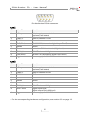
1
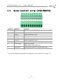
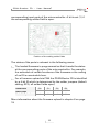
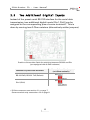
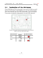
PCAN-Router FD
Universal, programmable Converter
for CAN FD and CAN
User Manual
Document version 1.0.0 (2015-11-11)
PCAN-Router FD – User Manual
Products taken into account
Product Name
Model
Part number
PCAN-Router FD
2 D-Sub connectors
IPEH-002214
PCAN-Router FD
Screw terminal strip (Phoenix)
IPEH-002215
CANopen® and CiA® are registered community trade marks of CAN in Automation
e.V.
All other product names mentioned in this document may be the trademarks or
registered trademarks of their respective companies. They are not explicitly marked
by “™” and “®”.
Copyright © 2015 PEAK-System Technik GmbH
Duplication (copying, printing, or other forms) and the electronic distribution of this
document is only allowed with explicit permission of PEAK-System Technik GmbH.
PEAK-System Technik GmbH reserves the right to change technical data without
prior announcement. The general business conditions and the regulations of the
license agreement apply. All rights are reserved.
PEAK-System Technik GmbH
Otto-Roehm-Strasse 69
64293 Darmstadt
Germany
Phone: +49 (0)6151 8173-20
Fax:
+49 (0)6151 8173-29
www.peak-system.com
[email protected]
Document version 1.0.0 (2015-11-11)
2
PCAN-Router FD – User Manual
Contents
1
1.1
1.2
1.3
2
2.1
2.2
3
3.1
3.2
3.3
3.4
Introduction
5
Properties at a Glance
Prerequisites for Operation
Scope of Supply
Connectors
5
6
6
7
D-Sub Connectors (IPEH-002214)
Screw terminal strip (IPEH-002215)
Hardware Configuration
7
9
10
4-Bit Coding
Supply of External Devices Via the D-Sub
Connector
Two Additional Digital Inputs
Termination of the CAN Busses
10
12
13
14
4
Startup Procedure
15
5
Software
16
5.1 Installing the GNU ARM Toolchain
5.2 Library
5.3 Firmware Examples
5.3.1
Compiling a Firmware Example
16
17
17
18
6
19
6.1
6.2
6.3
7
Uploading Firmware via CAN
System Requirements
Preparing Hardware and Software
Sending the Firmware
Technical Specifications
3
19
19
21
25
PCAN-Router FD – User Manual
Appendix A
CE Certificate
27
Appendix B
Dimension Drawings
28
4
PCAN-Router FD – User Manual
1
Introduction
The PCAN-Router FD has two CAN channels that support the new
CAN FD standard in addition to the conventional CAN 2.0 specification. The module behavior and the data exchange between the two
channels are freely programmable. Thus, for example, a conversion
of CAN to CAN FD and vice versa is possible and new CAN FD
applications can be integrated into existing CAN 2.0 networks.
Using the programming library and the GNU compiler for C and
C++, a firmware is created and then transferred to the module via
CAN. On delivery, the PCAN-Router FD is using a demo firmware
whose source code is contained as example in the scope of supply.
1.1
Properties at a Glance
Microcontroller NXP LPC4078 (ARM Cortex M4 with FPU,
120 MHz)
4 kByte On-Chip-EEPROM
4 MByte SPI Flash
Two CAN FD channels (protocols CAN FD ISO, CAN FD non-ISO,
CAN 2.0 A/B)
CAN bit rates from 25 kbit/s up to 1 Mbit/s
CAN FD bit rates for the data field (max. 64 bytes) from 25 kbit/s
up to 12 Mbit/s
NXP CAN transceiver TJA1044GT
Status indication with two dual-color LEDs
Connections via two 9-pin D-Sub connectors or a 10-pin screw
terminal strip (Phoenix)
5
PCAN-Router FD – User Manual
RS-232 interface for serial data transmission
1 I/O pin: digital output, digital input
2 additional digital inputs as an alternative to RS-232
Supply voltage from 8 to 30 V DC
Extended operating temperature range of -40 to +85 °C (-40 to
+185 °F)
New firmware can be loaded via CAN interface
1.2
Prerequisites for Operation
Power supply in the range of 8 to 30 V DC
For uploading a new firmware via CAN:
• CAN interface of the PCAN series for the computer (e.g.
PCAN-USB)
• Operating system Windows 10, 8.1, 7, Vista (32-/64-bit)
1.3
Scope of Supply
PCAN-Router FD in aluminum casing (optionally with DIN rail
mounting)
IPEH-002215: mating connector (Phoenix)
Windows development software (toolchain with GCC ARM
Embedded, flash program)
Library with programming examples
Manual in PDF format
6
PCAN-Router FD – User Manual
2
Connectors
Depending on the model, the PCAN-Router FD has the following
connectors:
IPEH-002214: two 9-pin D-Sub connectors (m)
IPEH-002215: one 10-pole screw terminal strip
Besides the primary functions (voltage supply, CAN FD incl. CAN
2.0), there are miscellaneous functions that can be used as needed:
RS-232 interface for serial data transmission
1 I/O pin: digital output, digital input
2 additional digital inputs as an alternative to RS-232 (must be
configured via hardware, see chapter 3 on page 10)
“Boot” input for activation of the CAN bootloader for firmware
upload (see chapter 6 on page 19)
The following subsections describe each connector assignment.
2.1
D-Sub Connectors (IPEH-002214)
The two D-Sub connectors are used for the CAN FD channels CAN1
and CAN2. The CAN lines (CAN_H, CAN_L) are laid out corresponding to the CiA® 102 specification.
The power supply of the PCAN-Router FD can be done via both DSub connectors. The supply connections Ub1 and Ub2 are connected
internally in a non-reactive configuration. This means that also
different power sources can be connected.
7
PCAN-Router FD – User Manual
Pin distribution D-Sub connector
CAN1
Pin
Identifier
Function
1
+5V opt.
5-Volt supply external device
(optional, see below)
2
CAN1_L
CAN FD channel 1 Low
3
GND
Ground
4
RxD (Din1)
RS-232 RxD (alternative digital input Din1 1)
5
Shield
Shield
6
Boot
Activation CAN bootloader (High level)
7
CAN1_H
CAN FD channel 1 High
8
TxD (Din2)
RS-232 TxD (alternative digital input Din21)
9
Ub1
Power supply 8 - 30 V DC
Pin
Identifier
Function
1
+5V opt.
5-Volt supply external device
(optional, see below)
2
CAN2_L
CAN FD channel 2 Low
3
GND
GND
4
-
Not used
5
Shield
Shield
6
-
Not used
7
CAN2_H
CAN FD channel 2 High
8
Din0 / Dout
Digital input Din0,
digital output Dout (600 mA)
9
Ub2
Power supply 8 - 30 V DC
CAN2
1
For the corresponding hardware configuration, see section 3.3 on page 13.
8
PCAN-Router FD – User Manual
2.2
2
Screw terminal strip (IPEH-002215)
Terminal
Identifier
1
Ub
Function
Power supply 8 - 30 V DC
2
GND
Ground
3
CAN1_L
CAN FD channel 1 Low
4
CAN1_H
CAN FD channel 1 High
5
CAN2_L
CAN FD channel 2 Low
6
CAN2_H
CAN FD channel 2 High
7
Boot
Activation CAN bootloader (High level)
8
Din0 / Dout
Digital input Din0,
digital output Dout (600 mA)
9
RxD (Din1)
RS-232 RxD (alternative digital input Din1 2)
10
TxD (Din2)
RS-232 TxD (alternative digital input Din22)
For the corresponding hardware configuration, see section 3.3 on page 13.
9
PCAN-Router FD – User Manual
3
Hardware Configuration
For special applications, several settings can be done on the circuit
board of the PCAN-Router FD by using solder jumpers.
4-bit coding of the hardware for polling by the firmware
Supply of external devices with 5 Volts via the D-Sub connector
(only IPEH-002214)
Use of two additional digital inputs (Din1, Din2) instead of the
serial RS-232 interface
Termination of the CAN busses with 120 Ω
Proceed as follows to perform soldering on the circuit board:
Attention! Electrostatic discharge (ESD) can damage or destroy
components on the circuit board. Take precautions to avoid
ESD when handling the circuit board.
1.
Remove the screws from both sides of the PCAN-Router FD
casing. With the D-Sub version, in addition, remove the
screws besides one of the D-Sub connectors.
2.
Pull the circuit board out of the casing profile.
3.
Set the solder jumper(s) on the circuit board according to
the desired settings. During this procedure take especially
care not to produce unwanted short circuits on the board.
4.
Afterwards, assemble the components in reverse order.
3.1
4-Bit Coding
The circuit board of the PCAN-Router FD has four coding solder
fields (ID0 to ID3) in order to allocate a permanent status to the
10
PCAN-Router FD – User Manual
corresponding input ports of the microcontroller. A bit is set (1) if
the corresponding solder field is open.
Position of the coding solder fields
The status of the ports is relevant in the following cases:
The loaded firmware is programmed so that it reads the status
at the corresponding ports of the microcontroller. For example,
the activation of certain functions of the firmware or the coding
of an ID is conceivable here.
For a firmware upload via CAN the PCAN-Router FD is identified
by a 4-bit ID which is determined by the solder jumpers (default
setting: ID15, all solder fields open).
Solder field
ID0
ID1
ID2
ID3
Binary digit
0001
0010
0100
1000
1
2
4
8
Decimal equivalent
More information about the firmware upload in chapter 6 on page
19.
11
PCAN-Router FD – User Manual
3.2
Supply of External Devices via the DSub Connector
Only product model IPEH-002214 (D-Sub connectors)
On the circuit board of the PCAN-Router FD, a 5-Volt supply can
optionally be routed to each pin 1 of the D-Sub connectors CAN1
and CAN2. Thus, devices with low power consumption (e.g. bus
converters) can be directly supplied via the CAN connector. The
current consumption may not exceed 100 mA per connector.
Position of the solder fields for the supply of external devices
(for D-Sub connector CAN1 on the left, for CAN2 on the right)
5-Volt supply
D-Sub connector
None
(Default)
CAN1 (left)
CAN2 (right)
12
Pin 1
PCAN-Router FD – User Manual
3.3
Two Additional Digital Inputs
Instead of the preset serial RS-232 interface for the serial data
transmission, two additional digital inputs (Din1, Din2) can be
assigned to the corresponding pins or screw terminals 3. This is
done by moving two 0-Ohm resistors (alternatively solder jumpers).
Position of the solder fields for switching between RS-232 and Din
(pre-equipped with 0-Ohm resistors)
Positions of the solder jumpers
(or 0-Ohm resistors)
Function for pins/screw terminals
RS-232 RxD, RS-232 TxD (Default)
Din1 (Din2)
3
D-Sub connectors: see section 2.1 on page 7
Screw terminal strip: see section 2.2 on page 9
13
PCAN-Router FD – User Manual
3.4
Termination of the CAN Busses
If the PCAN-Router FD is connected to one end of a CAN bus and if
there's no termination of the CAN bus yet, an internal termination
with 120 Ω between the lines CAN_H and CAN_L can be activated.
Termination is possible independently for both CAN channels.
Position of the solder fields for the termination of the CAN bus
(CAN1 on the left, CAN2 on the right)
CAN Channel
Without termination
(Default)
CAN1
CAN2
14
With termination
PCAN-Router FD – User Manual
4
Startup Procedure
The PCAN-Router FD is activated by applying the supply voltage to
the respective connectors (see chapter 2 Connectors on page 7). The
firmware in the flash memory is subsequently run.
On delivery, the PCAN-Router FD is equipped with an example
firmware which forwards CAN messages 1:1 between both CAN FD
channels (CAN FD ISO, 500 kbit/s nominal, 4 Mbit/s data). An incoming CAN message causes a change between green and orange of
the LED status indication for the respective CAN channel.
The source code for the example firmware 1_ROUTING and further
examples is included on the supplied DVD in the following directory
branch:
/Develop/Microcontroller hardware/PCAN-Router FD/Example/
15
PCAN-Router FD – User Manual
5
Software
This chapter covers the installation of the GNU ARM toolchain for
Windows and gives notes about the software library and the
firmware examples.
Software, source code, and additional information are included on
the supplied DVD in the following directory branch:
/Develop/Microcontroller hardware/PCAN-Router FD/
5.1
Installing the GNU ARM Toolchain
To compile the code examples and the custom firmware code under
Windows, install the supplied GNU ARM toolchain on your computer. The toolchain is collection of tools to develop applications for
ARM processors and corresponding microcontrollers on Windows
platforms. The collection includes a compiler for C and C++ as well
as Make utilities.
System requirement: Windows 10, 8.1, 7, Vista (32-/64-bit)
Proceed as follows to install the toolchain:
1.
From the directory branch on the provided DVD mentioned
above, change to the Compiler subdirectory.
2.
Start the setup program for GCC ARM Embedded
(gcc-arm-none-eabi-*.exe) and follow its instructions.
Make sure that you enable the option Add path to
environment variable on the last page.
3.
Afterwards, start the setup program for PEAK-System Make
Utilities (PEAK-MakeUtils*.exe) and follow its
instructions.
16
PCAN-Router FD – User Manual
In the system environment, the installation programs create search
paths for the executable files. These new search paths are effective
only for programs and command prompts that are started
afterwards.
5.2
Library
The development of applications for the PCAN-Router FD is supported by the library libPCAN-Router_FD_*.a (* stands for version
number), a binary file. You can access all resources of the PCANRouter FD by means of this library. Die library is documented in the
header files (*.h) which are located in the inc subdirectory of each
example directory.
5.3
Firmware Examples
On the DVD, the Example subdirectory contains source code for
several firmware examples that you can use and test directly and
that you can reuse for custom firmware.
On delivery, the PCAN-Router FD is equipped with the example
firmware 1_ROUTING which forwards CAN messages 1:1 between
both CAN FD channels (CAN FD ISO, 500 kbit/s nominal, 4 Mbit/s
data). An incoming CAN message causes a change between green
and orange of the LED status indication for the respective CAN
channel.
17
PCAN-Router FD – User Manual
5.3.1
Compiling a Firmware Example
Do the following to compile a firmware example under
Windows:
1.
From the provided DVD, copy the subdirectory of the
desired example from the Example directory to the local
hard disk.
2.
Open a command prompt by using the Windows Start
menu. Alternatively you can press the key combination
á + R and enter cmd.exe as program to be executed.
3.
At the command prompt, change to the previously copied
directory.
4.
Execute the following command in order to clean up the
target directories (e.g. out) from files that have been
generated earlier:
make clean
5.
Execute the following command to compile the firmware
example:
make all
If the compiler has finished without errors (“Errors: none”),
you can find the firmware file with the extension .bin in the
subdirectory out. This file is then used for firmware upload
to the PCAN-Router FD.
18
PCAN-Router FD – User Manual
6
Uploading Firmware via CAN
The microcontroller in the PCAN-Router FD is equipped with new
firmware via CAN. The scope of supply includes the Windows
program PCAN-Flash to transfer the firmware from the computer to
the PCAN-Router FD.
6.1
System Requirements
The following prerequisites must be given, so that the PCANRouter FD can be updated with new firmware:
CAN interface of the PCAN series for the computer (e.g. PCANUSB)
CAN cabling between the CAN interface and the PCANRouter FD with proper termination (120 Ω on each end of the
CAN bus)
Operating system Windows 10, 8.1, 7, Vista (32-/64-bit)
If you want to update several PCAN-Router FD connected to the
same CAN bus, you must assign a unique ID to each router. See
section 3.1 4-Bit Coding on page 10.
6.2
Preparing Hardware and Software
Perform the following steps for preparation of the hardware:
1.
Switch the PCAN-Router FD off by disconnecting it from the
power supply.
19
PCAN-Router FD – User Manual
2.
Establish a connection between “Boot” and the power
supply (“Ub1”, “Ub2”, or “Ub”) at the connectors of the
PCAN-Router FD.
Connection at D-Sub connector CAN1
between the pins 6 and 9
Connection at the screw terminal
strip between terminals 1 and 7
This measure later applies the “Boot” connection with a
High level.
3.
Connect a CAN bus of the PCAN-Router FD with a CAN
interface connected to the computer. Pay attention to the
proper termination of the CAN cabling (2 x 120 Ω).
Attention! Risk of short circuit! A CAN cable with D-Sub
connectors must not have a connection on pin 6, as it can be
seen on 1:1 cables, for example. At other CAN nodes (e.g. a
CAN interface of the PCAN series) this line may be applied to
the mass. Damage or destruction of the electronics is a possible
consequence.
Perform the following steps for preparation of the software:
1.
On the supplied DVD, change to the following directory:
/Develop/Microcontroller hardware/PCAN-Router FD/
2.
Copy the subdirectory PcanFlash to the local hard disk.
The contained Windows software that copies the Firmware
via CAN (PcanFlash.exe) can only be started from a data
carrier that is writable.
20
PCAN-Router FD – User Manual
6.3
Sending the Firmware
The process of uploading new firmware to the PCAN-Router FD
is as follows:
1.
Ensure that a connection is established between the “Boot”
and “Ub1”, “Ub2”, or “Ub” connections of the PCAN-Router
FD (details: see above).
2.
Switch on the PCAN-Router FD by applying a supply
voltage.
Due to the High level at the “Boot” connection, the PCANRouter FD starts the CAN bootloader. This can be determined by the status LEDs:
LED
State
Color
CAN1
quickly blinking
orange
CAN2
on
orange
3.
Run the program PcanFlash.exe under Windows from the
local hard drive.
4.
Click on the
box.
5.
From the Hardware Profile dropdown list, select the PCANRouter FD entry.
(Options) button in order to call up the dialog
21
PCAN-Router FD – User Manual
6.
Click on the … button next to the File name field in order to
select the desired firmware file (*.bin) to be uploaded.
7.
Click on the OK button.
8.
Make sure that the PCAN-Flash program is connected with
500 kbit/s to the available CAN interface at the computer.
PCAN-Flash: Display of a connection in the status bar on the bottom.
22
PCAN-Router FD – User Manual
If not, click the (Connect) button in order to change the
selection in the according dialog box.
9.
Click the (Detect) button in order to detect the PCANRouter FD connected to the CAN bus.
An entry for the PCAN-Router FD appears in the main
window.
10. Select the entry for the PCAN-Router FD.
23
PCAN-Router FD – User Manual
11. Click the (Program) button in order to start uploading the
new firmware to the PCAN-Router FD.
Observe the status indication at the bottom of the window.
The process was successful if the last message to appear is
“Flashing of module(s) finished!”.
12. Disconnect the power supply from the PCAN-Router FD.
13. At the PCAN-Router FD, disconnect the connection between
“Boot” and the power supply (“Ub1”, “Ub2”, or “Ub”).
You can now use the PCAN-Router FD with the new firmware.
24
PCAN-Router FD – User Manual
7
Technical Specifications
Functionality
Microcontroller
Microcontroller NXP LPC4078 (ARM Cortex M4 with
FPU, 120 MHz)
Add-on memory
4 kByte, EEPROM
4 MByte SPI Flash
CAN
2 x CAN FD (ISO, non-ISO, CAN 2.0)
CAN bit rates
Arbitration phase:
25 kbit/s - 1 Mbit/s
Data field (CAN FD): 25 kbit/s - 12 Mbit/s
Transceiver
NXP TJA1044GT
RS-232
RxD and TxD serial connections with RS-232 levels
Digital inputs (Din)
Low-active, max. level Ub
Digital output (Dout)
Low-side, max. 600 mA
Status indication
2 duo LEDs
Connectors
IPEH-002214: 2 x D-Sub connector, 9-pin,
assignment according to specification CiA® 102
IPEH-002215: 1 x screw terminal strip, 10-pole, pitch
3.81 mm (Phoenix Contact MC 1,5/10-ST-3,81 1803659)
Power supply
Supply voltage (Ub)
8 - 30 V DC
Current consumption
max. 150 mA at 8 V
max. 100 mA at 12 V
max. 50 mA at 30 V
Measures
Size
Casing:
70 x 55 x 24 mm (L x W x H)
Circuit board: 65 x 51 mm (L x W)
See also dimension drawings in Appendix A on
page 27
Weight
IPEH-002214 (D-Sub):
IPEH-002215 (Phoenix):
25
100 g
89 g
PCAN-Router FD – User Manual
Environment
Operating temperature
-40 - +85 °C (-40 - +185 °F)
Temperature for storage
and transport
-40 - +100 °C (-40 - +212 °F)
Relative humidity
15 - 90 %, not condensing
EMC
EN 61326-1:2013-07
EC directive 2004/108/EG
Ingress protection
(IEC 60529)
IP20
26
PCAN-Router FD – User Manual
Appendix A
CE Certificate
27
PCAN-Router FD – User Manual
Appendix B
Dimension Drawings
The figures do not show the original size.
28