1
modifier.
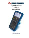
For more details on the uses of each button, refer to Section 3, “OPERATION THE METER FROM
THE FRONT PANEL.”
SELECTING A MEASUREMENT RANGE
Measurement ranges can be selected automatically by the meter in “autorange” or manually by the
user. In the autorange mode, the meter selects the appropriate range for the measurement reading.
To manually select a range, press AUTO to toggle in (and out) of the manual ranging mode, or press
or
. In the manual range mode, press
or
to up range or down range to the desired
range. For more details on ranging, refer to “RANGING” in Section 3.
TAKING SOME BASIC MEASUREMENTS
WARNING
READ “MULTIMETER SAFETY” BEFORE OPERATING THIS METER.
The following procedures describe the basics of taking common measurements from the front panel.
These procedures are provided for the user who needs to get started quickly, but dose not want to
read the rest of the manual at this time. However, in order to take full advantage of your meter, you
should read the remainder of this manual carefully and completely.
WARNING
TO AVOID ELECTRICAL SHOCK OR DAMAGE TO THE METER, DO NOT APPLY MORE THAN
1000V (PEAK) BETWEEN ANY TERMINAL AND EARTH GROUND. THE METER IS PROTECTED
AGAINST OVERLOADS UP TO THE LIMITS SHOWN IN TABLE 3-1. EXCEEDING THESE LIMITS
POSES A HAZARD TO THE METER AND OPERATOR.
Measuring Voltage, Resistance, or Frequency
To measure voltage, resistance, or frequency, press the desired function button and connect the test
leads as shown in Figure 2-4. The meter will select the appropriate range in the autorange mode.
Measuring Current
To measure current, insert the red test lead in the
mA
input terminal for currents up to 330mA or in the 10A input
terminal for higher current, and insert the black test lead in the
COM terminal.
Connect the test leads as shown in Figure 2-5.
mA
10A FUSED
1000V
750V
MAX
500mA 250V
FAST FUSE
ALL INPUTS
1KV MAX
DC Voltage,Pesistance
or AC Voltage
Figure 2-4. Measuring DC Voltage, Resistance, AC Voltage
10A FUSED
A
CURRENT
SOURCE
1000V
750V
mA
mA
500mA 250V
FAST FUSE
MAX
NOTE
After measuring high current using the 10A input, thermal
voltages are generated that may create errors when making
low-level dc measurements of volts, current, or ohms. To make
the most accurate measurements, allow up to ten minutes for the
thermals to settle out.
ALL INPUTS
1KV MAX
Figure2-5. Measuring Current
Diode/Continuity Testing
The continuity test determines whether a circuit is intact (i.e., has a resistance less than about 150Ω).
To perform a continuity test, press
, and connect the test leads as
shown in Figure 2-6. The beeper emits a continuous beep when the input
drops below 150Ω (Beep condition can be changed, refer to “Changing the
Power-UP Configuration” later in Section 3), and the readings for the test
circuit are displayed.
10A FUSED
+
1000V
750V
MAX
-
TEST
CIRCUIT
mA
500mA 250V
FAST FUSE
ALL INPUTS
1KV MAX
5