1
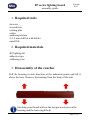
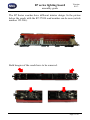
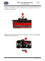
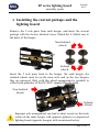
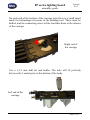
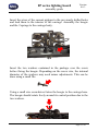
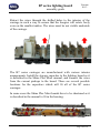
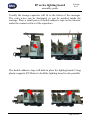
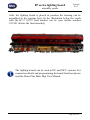
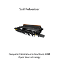
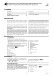
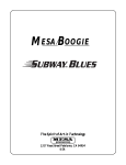
B7 series lighting board
assembly guide
- version 0.0.3 –
© Copyright NMJ 2014
All rights reserved
B7 series lighting board
assembly guide
Version
0.0.3
Please read this manual carefully before carrying out the
installation!!! Although our products are very robust, incorrect
wiring may destroy the module!
During the operation of the device the specified technical parameters
shall always be met. At the installation the environment shall be fully
taken into consideration. The device must not be exposed to moisture
and direct sunshine.
A soldering tool may be necessary for the installation and/or
mounting of the devices, which requires special care.
During the installation it shall be ensured that the bottom of the
device should not contact with a conductive (e.g. metal) surface!
Page 2 of 14
B7 series lighting board
assembly guide
Version
0.0.3
Content
1.
2.
3.
4.
5.
Required tools.............................................................................. 4
Required materials ....................................................................... 4
Disassembly of the coaches ......................................................... 4
Installing the current pickups and the lighting board .................. 7
Notes .......................................................................................... 13
Page 3 of 14
B7 series lighting board
assembly guide
Version
0.0.3
1. Required tools
-tweezer
-screwdriver
-cutting plier
-cutter
-soldering station
-1-1.2 mm drill bit with holder
-small file
2. Required materials
-B7 lighting kit
-adhesive tape
-soldering wire
3. Disassembly of the coaches
Pull the housing in side direction at the indicated points and lift it
above the base. Remove the housing from the body of the unit.
Inserting your thumb nails in the boogie area between the
housing and the base might help.
Page 4 of 14
B7 series lighting board
assembly guide
Version
0.0.3
The B7 Series coaches have different interior design. In the picture
below the coach with the B7 27030 road number can be seen (article
number 122.206).
Both boogies of the coach have to be removed.
Page 5 of 14
B7 series lighting board
assembly guide
Version
0.0.3
Release the holding screws as indicated in the picture below. Use a
small size screwdriver.
While removing the boogie from the carriage, preserve the 2 springs
and the screw for later use.
Page 6 of 14
Version
0.0.3
B7 series lighting board
assembly guide
4. Installing the current pickups and the
lighting board
Remove the 2 axle pairs from each boogie, and insert the current
pickups with the factory attached wires. Match the 4 folded ears to
the holes of the boogie.
Non-Isolated
wheels
Isolated
wheels
Insert the 2 axle pairs back to the boogie. On each boogie, the
isolated wheels must be on the same side, and on the two boogies
they are mirrored. Only with this wheel arrangement is possible to
collect both polarities of the DC/DCC signals from the track.
Non-Isolated
wheels
Isolated
wheels
Improper axle arrangement can lead to short circuit on the track
(axles on the same boogie with opposite polarity) or unpowered
lighting board (opposite boogies with un-mirrored axles).
Page 7 of 14
B7 series lighting board
assembly guide
Version
0.0.3
On each end of the bottom of the carriage base there is a small insert
made for technological reasons in the molding tool. These must be
drilled, and the connecting wires will be lead thru them to the interior
of the carriage.
Right end of
the carriage
Use a 1-1.2 mm drill bit and holder. The hole will fit perfectly
between the 2 metal pates in the bottom of the body.
Left end of the
carriage
Page 8 of 14
B7 series lighting board
assembly guide
Version
0.0.3
Insert the wires of the current pickups to the previously drilled holes
and lead them to the interior of the carriage. Assembly the boogie
and the 2 springs to the carriage body.
Insert the two washers contained in the package over the screw
before fixing the boogie. Depending on the screw size, the internal
diameter of the washers may need minor adjustments. This can be
done using a small file.
Using a small size screwdriver fasten the boogie to the carriage base.
The boogie should rotate freely around its central position due to the
two washers.
Page 9 of 14
B7 series lighting board
assembly guide
Version
0.0.3
Retract the wires through the drilled holes to the interior of the
carriage in such a way to ensure that the boogies will rotate freely
even on the smallest radius. The wires must be not visible underside
of the carriage.
The B7 series carriages are manufactured with various interior
arrangements. Install the storage capacitor to the lighting board as it
is described in the Shine Plus Maxi manual, and connect the wires
from the current pickups to the board. There are several possible
locations for the capacitors which will fit all of the B7 series
carriages.
In some cases the Shine Plus Maxi boards have to be shortened as it
is described in the manual to fit in the housing.
Page 10 of 14
B7 series lighting board
assembly guide
Version
0.0.3
Usually the storage capacitor will fit to the toilets of the carriages.
The extra wires can be shortened, or can be masked inside the
carriage. Place a small piece of double adhesive tape on the interior,
under the contact surface of the capacitors.
The double adhesive tape will hold in place the lighting board. Using
plastic supports (PS Shine) to hold the lighting board is also possible.
Page 11 of 14
B7 series lighting board
assembly guide
Version
0.0.3
After the lighting board is placed in position the housing can be
assembled to the carriage base. In the illustration below the coach
with the B7-3 22779 road number can be seen (article number
124.301) before the final assembly.
The lighting boards can be used in DC and DCC systems. For
connection details and programming the board functions please
read the Shine Plus Maxi Digi User Manual.
Page 12 of 14
B7 series lighting board
assembly guide
Version
0.0.3
5. Notes
Page 13 of 14
B7 series lighting board
assembly guide
Version
0.0.3
Copyright © 2014 NMJ
All rights reserved
The information in this document is subject to change without
notice
Page 14 of 14