1
SOUND
Zipper
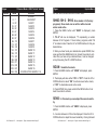
Power Cord Daisy Chain
R
8200
31000
B
660
200
96
61
41
53000
16000
7500
4400
2800
( LUX ) W
2650
1200
8400
4100
695
POWER
DMX+,DMX-,COMMON
cables. Do not
use the ground lug on the XLR connector. Do not connect the cable’s shield conductor to the ground lug or allow the shield
conductor to come in contact with the XLR’s outer casing. Grounding
the shield could cause a short circuit and erratic behavior.
COMMON
1350
DMX512 OUT
3-PIN XLR
0
1.0
0.35
2.0
0.07
SOUND
3.0
0.105
Zipper
REMOTE
4.0
CONTROL
INPUT
0.14
INPUT
1
2
DMX +
3
DMX -
3
1
DMX512 IN
3-PIN XLR
2
3
1
2
Figure 2
0m(
)
XLR Female Socket
XLR Male Socket
1 Ground
Distance(m)
POWER
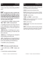
Notice: Be sure to
follow figures two and three when making your own
DMX512
441
2050
2
Diameter(m)
Set Up
chained and cannot be split.
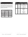
Photometric Chart
G
SOUN
CONTROL
INPUT
Zipper
With this feature you can connect the fixtures to one another
using the IEC input and output sockets. The quantity that can be
connected is 10 fixtures maximum for 120V and 18 fixtures maximum for 240V. After the maximum fixtures has been reached you
will need to use a new power outlet. They must be the same fixtures. DO NOT mix fixtures.
Zipper
SOUND
CONTROL
INPUT
5.0
0.175
OUTPUT
REMOTE
CONTROL
INPUT
SOUND
2 Cold
2 Cold
INPUT
OUTPUT
Pin 1 = Ground
REMOTE
CONTROL
INPUT
INPUT
OUTPUT
Pin 2 = Data Compliment (negative)
3 Hot
Dimmer Curve Chart
XLR Pin Configuration
1 Ground
SOUND
Termination
avoids sign
and interfere
to connect a
120 Ohm 1/4
and PIN 3 (
3 Hot
Pin 3 = Data True (positive)
Figure 3
Special Note: Line Termination. When longer runs of cable are
POWER
POWER
POWER
used, you may need to use a terminator on the last unit to avoid erratic
behavior. A terminator is a 110-120 ohm 1/4 watt resistor which is connected between pins 2 and 3 of a male XLR connector (DATA + and
DATA -). This unit is inserted in the female XLR connector of the last
unit in your daisy chain to terminate the line. Using a cable terminator
(ADJ part number Z-DMX/T) will decrease the possibilities of erratic
behavior.
DMX512
DMX+,DMX-,COMMON
COMMON
DMX512 OUT
3-PIN XLR
(Fade Time)
Ramp Effect
1
2
DMX +
3
DMX -
(Fade Time)
0m(
30
)
3
1
2
DMX512 IN
3-PIN XLR
3
1
2
Termination reduces signal errors and
avoids signal transmission problems
and interference. It is always advisable
to connect a DMX terminal, (Resistance
120 Ohm 1/4 W) between PIN 2 (DMX-)
and PIN 3 (DMX +) of the last fixture.
XP-15R SZ
Standard
Stage
Distance(m)
TV
Diameter(m)
0
1.0
0.5
2.0
1.0
3.0
1.6
4.0
2.1
5.0
2.6
33000
1700
Architectural
Theatre
ADJ Products, LLC - www.adj.com - Zipper Instruction Manual Page 21
Figure 4
8300
470
3700
200
ADJ Products, LLC - www.adj.com - Zipper Instruction Manual Page 6
Distance(m)
0
5.0
10.0
15.0