1
United States Patent 1191
[11] E
Re. 31,441
[45] Reissued Nov. 15, 1983
Nutting et a1.
[54] PLAYER OPERATED GAME APPARATUS
[75] Inventors: David J. Nutting; Jeffrey E.
Frederiksen, both of Milwaukee,
OTHER PUBLICATIONS
Bally Alley Service Manual; Bally Manufacturing Corp.;
Jan. 1978.
Popular Electronics,‘ "Altair 8800;" Jan. 1975; pp. 33-38.
Wis.
Popular Science; “Games Computers Play”; Oct. 1970;
[73] Assignee: Bally Manufacturing Corporation,
p. 44.
EE/Systems Engineering Today; “Electronic Plays the
Chicago, Ill.
Pins”; Nov. 1973; pp. 27-31.
The Semiconductor Data Library; Motorola, Inc; 1973;
[21] Appl. No.: 936,784
pp. 2-53.
[22] Filed:
Aug. 25, 19711
General Electric Transistor Manual; 1964; pp. 29, 30.
Intel Intellec 4 and Micro Computer Modules Reference
Manual; 1974; pp. 15-17, 39, 40.
Related US. Patent Documents
The Optoelectronics Data Book for Design Engineers;
Reissue of:
[64]
[51]
1970-1971; pp. 212-228.
MCS-4 Microcomputer Set Users Manual; 1974; pp. 1-6,
Patent No.:
4,093,232
Issued:
Jun. 6, 1978
51-54.
Appl. No.:
576,980
Filed:
May 13, 1975
Electronic Design; Apr. 12, 1973; pp. 84-89.
Int. Cl.3 .............................................. .. A631? 7/00
[52]
................... .. 273/121 A
[58]
Field of Search ............... .. 273/1 E, 1 GC, 54 C,
273/85 G, 118 A, 119 A, 121 A, 122 A, 125 A,
126 A, DIG. 28, 143 R, 143 C; 235/1 B, 1 GA,
156; 179/15 AL; 364/410-412; 445/1; 340/323
R; 377/5
[56]
References Cited
8/1949
9/1957
Durant .......................... .. 273/121 A
Durant .... ..
273/125 A
2,864,619 12/1958 Burnside
3,703,288 11/1972 Vogel et a]. ..
3,715,746
2/1973
Hatano ........... ..
3,809,395 5/1974 Allison et a1.
3,874,669 4/1975 Ariano et a1.
3,889,956
6/1975
Castle ......... ..
3,907,290 9/ 1975 Fischer et a1.
4,008,893
2/1977
4,026,555
5/1977 Kirschner et a1.
4,087,855
5/ 1978
.. 273/121 A
273/126 A
340/3658
273/1 E
273/85 G
273/1 E X
273/54 C
Yoseloff .................. .. 273/85 G
273/85 G
Bennett et a1. .................... .. 364/200
FOREIGN PATENT DOCUMENTS
2038597 12/1970
France .
“Programmable Logic Controllers-Painless Program
ming to Replace the Relay Bank"; Apr. 1971; pp. 49-60.
Application Notes Pamllel Processing System; 1972; pp.
1-25.
U.S. PATENT DOCUMENTS
2,479,707
2,806,701
Process Instruments and Controls Handbook; 1975; pp.
8/34-8/47.
Electronics; Oct. 25, 1973; pp. 71-106.
Motorola Monitor; Dec. 1973; pp. 5-11.
Electronics; Mar. 21, 1974; pp. 19-20.
Litronix Appnote 3; 1971; pp. 1-4.
Electronics; Mar. 1, 1973; pp. 63-64.
"The Potential Impact of Microprocessor Technol
ogy"; Dec. 1974; pp. 1-33.
“Minicomputers & Microcomputers The Squeeze Is
On”; 1974; pp. 79-82, 85-88, 113-114; 140-152,
211-218.
Electronics,’ Jun. 27, 1974; pp. 69-70.
Electronics; Jul. 11, 1974; pp. 92-95.
Faircltild TTL Applications Handbook; Aug. 1973; pp.
1/5, 1/6, 3/1-3/24, 15/3-15/4.
Application Notes; “Mos/LS1 Timer-Controller Se
quencer TCS Device"; Apr. 1972; pp. 1-12.
Application Notes; “Programming Manual for Timer
Controller Sequencer”; Mar. 1972; pp. 1-15.
Application Notes; “Timer-Controller Sequencer (TCS)
Device Evaluation Unit;" Dec. 1972; pp. 1-6.
Re. 31,441
Page 2
Primary Examiner-Vance Y. Hum
Attorney, Agent, or Firm‘—Welsh & Katz
{57]
ABSTRACT
A pinball game has a playing ?eld with ball directing
lanes and targets and ?ipper elements for returning the
ball. A programmed logic array is connected to the
switches, response lamps, digit scoring lamps, and audi
ble devices. A matrix circuit is connected to the
switches and places information into a memory, the
output of which is connected through to activate lamps
and audible devices which produce a continuous output
if energized. A scanning decoder coupled to the matrix
circuit is driven from the programmed logic array.
95 Claims, 5 Drawing Figures
U.S. Patent
Nov. 15, 1983
Sheet 1 of 3
Re. 31,441
1249.2
LOGIC UNIT
swwcn INPUTS
DATA OUTPUTS
POWER/ 37
Q
I~—-TEsT BACK CABINET
MOTHER some
em: ADJUSTMENTS
@uTPu'r ELECTRONIC?‘
SCORE READOUT
5.2
GAME INDICATOR LIGHTS
GENERAL ILLUMINATION
SCORE LAMPS
gncx CABINET
/‘
TARGET INPUT SWITCHES
Sm" E / LIGHTS
95%55‘1.\ILLUMINATION
BUMPER / SOLENOIDS
PLAY FIELD
i.’
LOWER CABINET
LEFT com\
I000
00R
LINE A-C.
KN
-
'_"
U.S. Patent
Nov. 15, 1983
Sheet 3 of 3
I
I
I
I
I
I
l
l
I
I|runl L
GKIHuNPhnQJ-UOCEt
_
-
-
":25»!_
a
-
I
o
o
.
I
I
l
l
l
l
I
‘Iz
-
I
l
I
l
u
u
I
|
-
-
-
-
_
_
-
-
Re. 31,441
1.
Re. 31,441
2
cannot be readily and conveniently changed to over
come any of the assumed undesirable features. Such
games are, of course, in such demand, however, that
they are widely manufactured and sold even with pres
ent marketing restrictions and constraints. There is,
however, a need for a method of simplifying the game
PLAYER OPERATED GAME APPARATUS
Matter enclosed in heavy brackets [ ] appears in the
original patent but forms no part of this reissue specifica~
tion; matter printed in italics indicates the additions made
by reissue.
design and apparatus which will permit the manufac
turer to adapt to rapidly changing market conditions
BACKGROUND OF THE INVENTION
This invention relates to player operated game appa
ratus and particularly to a game apparatus employing
multiple display means actuated in response to player
manipulated and controlled movement of elements and
particularly to a pinball game apparatus and the like.
and requirements. Of course, the game apparatus should
moves down under gravity forces through a maze of
display means such as visual and/or audio means and
provide economy in construction as well as in mainte
nance and operating costs.
SUMMARY OF THE PRESENT INVENTION
The present invention is particularly directed to such
Pinball type game apparatus is widely employed in 5 game apparatus wherein movement of an element is
selectively and partially controlled with respect to ele
various recreational establishments. Uniformly, such
games employ the ejection of a playing ball to the upper
ment activated response devices, which in turn are con
end of a downwardly inclined playing ?eld. The ball
nected in an isolated connection to activate automatic
alleys or lane forming elements, target bumper elements 20 the like wherein both stimulatory and numerical scoring
of various forms and the like. The movement through
the lanes and into engagement with several bumpers,
lane switches and the like complete suitable circuits to
display are provided. As the present invention is
uniquely applied to and develops a unique pinball game
apparatus, the invention is described in connection
therewith for purposes of reference. Generally, in ac
activate suitable display and scoring mechanisms. The
operator can partially control the movement of the ball 25 cordance with the present invention, the display means,
by limited jarring of the playing ?eld and generally
the element activated response means, and the inter
through the activation of manually operated ?ipper
locking control means are arranged into sequentially
control means which operate one or more dispersed
activated element groups and connected through a ma
trixing or multiplexing means to a programmed logic
means such as a microprocessor to provide a highly
pivotally mounted ?ipper arms on the upper surface of
the playing ?eld. Such games are widely available in
many different formats and arrangements. They almost
universally, however, employ a structure with an up
right back panel on which game indicating lights, digit
scoring and the like are displayed along with general
pictoral information with suitable illumination. Audible
improved control and response of the game apparatus.
The multiplexing means sequentially couples the acti
vated elements in the system at a sufficiently rapid re
35 petitive rate to effectively present a continuous moni
toring and presentation of the several display means,
devices such as bells or chimes are also normally incor
producing interconnection of the response means and
operation of the interlocking control means to properly
porated to respond to selected targets within the play
ing ?eld. In addition, scoring openings in the playing
monitor, score, and display during each cycle of the
?eld have switches to indicate receipt of a ball and
automatic rejecting means to propel the ball back onto 40 program. The processing system permits significant
cost reduction in the initial construction as well as con
the playing ?eld. Such devices are generally coin
venient changes in the basic approach of any given
structure. Generally, in accordance with the present
invention, the playing ?eld is constructed in accordance
with the usual construction to develop a plurality of
lanes, response target devices and ?ipper elements. The
operated and may provide for multiple operation
whereby two or more players can sequentially play the
game, with individual indication of the player, as well as
individual scoring and the like for limited competitive
purposes. In such games various controls must of course
several elements activate switch means and establish
signals to a common matrixing or multiplexing circuit.
be provided to control the response of the system as
well as providing interlocking controls for example in
response to insertion of proper coins and the like to
activate the system including the flipper controls. Fur
A programmed, logic array means rapidly and in cycli
50 cal manner scans the input lines coupled to the switch
ther the game will normally include an automatic tilt
whereby an unacceptable jarring of the playing ?eld
results in a termination of the game.
Such apparatus with the several elements as de~
means and detects the device operation and subse
quently correspondingly activates within each cycle the
proper visual output of display means which include the
conventional visual display lamp means, audible means
scribed have been constructed for many years employ 55 or visual display means as well as a digit display. In
accordance with a particular aspect of this invention the
ing hard wiring of the game system through an electro
mechanical control. Thus the various target input
digit display is developed through a suitable line seg
switches are connected directly to selectively control
ment generator. The switch means are thus connected
the target lights. Similarly, the ?ippers may be provided
to place the switch information into a memory system,
the output of which is connected through the same
matrix board to activate the desired visual and audible
with release devices responsive to the proper introduc
tion of coins to actuate an electrical interlock. Although
such systems have been widely employed, they have
been relatively expensive not only in initial cost but in
subsequent maintenance. Further, any single construc
tion is essentially related to a single game plan and thus 65
for providing a great variety of games, signi?cant indi
vidual design requirements ‘exist. Further, if a game
once designed and marketed ‘is not readily accepted, it
devices including visual display lamps, scoring digit
display means as well as audible devices. The switch
means further include interlocking monitoring means to
determine the status of the apparatus with respect to, for
example, the tilt condition, the receipt of an appropriate
input such as coins, credit condition, automatic addi~
tional game incentive in response to previous games
3
Re. 31,441
4
tion to the programmed logic array for storage of the
actuation thereof is also uniquely provided in another
scoring and the like during each cycle and operable to
provide a priority type control to the program logic
array. This information is also fed through the matrix
feature or aspect of the best embodiments to produce
noise immunity. Thus, the switches are connected to
board into the memory unit, the output of which is
selectively connected to the same matrix board. The
output from the multiplexing or matrix board is further
interconnected to the lamps and to the control solenoid
ground the inputs through the transistor switch means.
The turn~on time of the transistor inserts a time lag in
the circuit to the input switches, whch are coupled to
the same scan line of the matrix circuit, and effectively
makes the response immune to “noise“ or transients
to release the apparatus for play to thereby provide
complete interlocking control through the memory and
created in the switching.
Generally, in a highly practical construction a four
input port responds to the several playing ?eld inputs to
record the play while a four output port provides means
the matrix unit. The programmed logic array is a se
quential logic microprocessor with the input lines of the
matrix board sequentially scanned on a repetitive basis
with the information transmitted to the interlocks and
for driving of the lamps and selected auxiliary equip
to the display means to activate the device or the game
apparatus in accordance with the inputs and the mem 5 ment. A further output port provides a drive means to
.
the scoring boards and other auxiliary equipment. In
ory. The repetition rate or frequency is sufficiently
rapid to maintain the presentation and activation of the
addition, a separate test input line is connected into the
circuit through the multiplexing lines to maintain a
output means as if a direct pass through of the informa
continuous monitor and an interlock of the system for
tion from the switches to the output and control devices
20 subsequent play. Thus, the credit condition, as a result
was established.
of coins, is maintained and provided to sense the activa
The invention thus provides a convenient means for
tion of such switches. The test output is connected to
maintaining a generalized logical control for a game
the computer interrupt and operates the interrupt when
apparatus employing the advantages of a small memory
a corresponding multiplex line is actuated to provide for
system which can, of course, be readily adapted to a
conventional software control of the game response in 25 the automatic recording of such information. For exam
ple, it is, of course, essential that any coin introduced by
accordance with a relatively ?xed ?eld memory.
any player be automatically recorded and credited. The
More particularly, in a particular unique implementa
test line will respond to such a condition to momen
tion a small microprocessor is suitably housed in the
tarily interrupt the usual sequencing and automatically
back housing wall or box of a pinball unit and coupled
through a sixteen slot matrix board to a read only mem 30 maintain a continuous record of the credit conditions.
Similarly, a tilt condition will take precedence and pro
ory for activating of the display means and sensing of
vide automatic processing of the tilt condition.
the various switch conditions in combination with a
The multiplexing system develops the same input
continuous test and interlock system to maintain inter
locking control of the system while play is in operation
and storing of the condition with respect to subsequent
play of the apparatus. More particularly, in accordance
output ports providing various functions on a timed
35
with a particular constructional novel feature and em
bodiof the present invention, a multiplexing circuit is
division multiplexing control. The scanning rate will
generally be held to a minimum of 50 or 60 cycles per
second which is above the minimum ?icker rate of a
conventional display means and insures a continuous
display presentation with the scanning concept. ‘
driven from a random access memory to sequentially
In accordance with a further aspect and novel em
activate a plurality of multiplex input lines on a continu 40
ous cyclic basis and a similar parallel decoder is prefera
bodiment of this invention, the interfacing between the
switches and non-lamp outputs without suitable thermal
bly coupled to condition a main driving power output
inertia includes suitable opto-isolator devices or the like
as connected to operate the several playing compo
nents.
which inherently introduce an automatic memory or
Processing will further normally include a step com 45 storage function to permit the continuous scanning or
mand signal to simultaneously activate the multiplexing
cycle control concept as applied to the game apparatus.
decoder or sequencing system and simultaneously con
Thus, generally Applicant has found that the present
trol the interfacing drive to the display means to main
invention provides a highly improved game apparatus
tain precise synchronous relationship. This is particu
larly signi?cant to permit the use of relatively minimal
number of driver transistors or the like. The multiplex
ing output lines are coupled to provide information to
the random access memory and to drive the several
lamps, interlocks and control means. The lamp circuits
include suitable low beta driver transistors in series with 55
low voltage lamps, with a driving voltage signi?cantly
greater than the rated voltage. The circuits are com
having means to permit significant simpli?cation in the
initial cost and particularly pinball-type game apparatus
and the like with the production cost and maintenance
of the apparatus minimized and further readily adapts to
practical commercial implementation.
BRIEF DESCRIPTION OF THE DRAWINGS
The drawings furnished herewith illustrate a pre
ferred construction of the present invention in which
the above advantages and features are clearly illustrated
pleted once each programmed cycle and produce mo
as well as others which will be readily understood from
mentary high current lamp energization. However, the
average current is normal and the lamps will operate 60 the following description.
In the drawings:
without adverse effect and at a signi?cant economy.
Further, the transistors of limited capacity produce
FIG. 1 is a pictorial view ofa typical pinball machine
inherent current limiting on cold lamp start to further
apparatus;
increase lamp life and are less expensive than higher
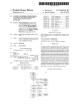
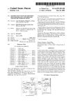
FIG. 2 is a block diagram showing the various por
capacity transistors. They, therefore, provide an inex
tions of the game apparatus in block diagram with line
pensive switch which can be readily and satisfactorily
interconnection between the several components;
applied in the game apparatus to again provide maxi
FIG. 3 is a side view diagrammatically illustrating the
mum economy. The input or response switch connec
component mounting and housing construction;
5
Re. 31,441
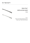
FIG. 4 is a diagrammatic illustration of multiplexing
arrangement for a particular pinball game unit as shown
in FIGS. 1-3; and
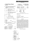
FIG. 5 is a circuit diagram illustrating a typical
known computer system interfaced with the game cir
cuit, portions of which are schematically shown to
clearly illustrate the present invention.
DESCRIPTION OF THE ILLUSTRATED
EMBODIMENT
Referring to the drawings and particularly to FIG. 1,
the present invention is illustrated applied to a typical
pinball game machine 1 including an upper game ?eld
6
A typical system is diagrammatically illustrated in a
matrix form in FIG. 4 for purposes of fully describing a
preferred embodiment of the present invention.
In addition, a coin receiving means is provided to
limit playing of the game to the introduction of coins. In
the illustrated embodiment of the invention, a pair of
redundant coin acceptors 20 are provided, to minimize
service requirements. Introduction of the coins into
either coin acceptor 20 will condition the apparatus for
the ?rst and second players with the response providing
for automatic and alternate play and scoring for the two
players. Access to a coin box, not shown, is provided by
a locked front door unit 21. The embodiment shown is
thus generally typical of the conventional pinball game
apparatus. The present invention is particularly directed
cabinet 2 supported by a plurality of legs 3 which locate
the cabinet 2 approximately at waist height of the usual 5
to the mounting and interconnection of such input
game player. The cabinet 2 includes a glass top 4 be
switch means, the lamp means, the digit scoring display
neath which a playing ?eld 5 is located. A manual ball
means and interlocking controls through a special con
feeding mechanism 6 is shown to the front for ejecting
necting board 22 to a programmed logic array means
of a round ball 7 to the upper end of the playing ?eld 5
from which it rolls downwardly under gravity forces
across the playing ?eld. In accordance with the usual
23, as diagrammatically shown in FIGS. 2 and 3. The
logic array means 23 and board 22 are constructed as a
small compact assembly which is readily mounted
constructions, the playing ?eld 5 includes left and right
within the back cabinet 16. The location of these ele
lane walls 8 adjacent the outer edges of the ?eld 2, with
ments provides extremely convenient construction and
suitable switch lever means 9, right and left bumpers 10, 25 subsequent servicing of the interconnection to the sev
as well as targets 11 and scoring opening 12 with lever
eral components of the playing ?eld 5, on the coin door
means, all located within the playing ?eld 2. The bum
21 and elements located within the lower play ?eld
pers 10 and openings 12 operate to propel the ball with
cabinet 2 and identi?ed in FIG. 2 as the lower cabinet
a rapid movement depending upon the direction from
by block diagram 24. The various components and logic
which the bumper engaged the members and establish 30 array means for controlling the apparatus are coupled
various scores when engaged. Further, when the ele
through a motherboard and the coin door for main
ments are engaged by the ball 7 to provide additional
control thereof. The board further provides intercon
scoring, various lights and audible display means are
nection to drive the display of the back panel and simul
taneously to activate the panel to receive signals from
energized to indicate the response element. For exam
ple, a target or a lane lamp may be activated as the ball 35 the playing ?eld switch means and to provide control to
engages a corresponding portion of the playing ?eld. In
the several components of the playing ?eld.
accordance with more conventional construction, the
Thus, FIG. 2 is a general layout of the apparatus in
apparatus also includes manually operated or controlled
?ippers 14 pivotally mounted to the bottom portion of
accordance with a teaching of the present invention to
more clearly illustrate and describe a preferred system
shown in FIGS. 4 and 5, and FIG. 3 illustrates the
the playing ?eld. The ?ippers 14 pivot for engaging the
ball 7 and returning it upwardly on the playing ?eld 5.
The ?ipper controls are conventionally in the form of
right and left buttons 15 provided on the corresponding
side walls of the cabinet 2 for manual operation by the
structural mounting of the components.
display and scoring of the play.
ing ?eld 5 and only activated during game play. The
Generally a main power supply connection from a
main AC power supply line 25 such as conventionally
employed in utility distribution systems in the United
45 States provides main power to the system through the
operator.
lower cabinet 2. The output power is applied directly to
Further, in accordance with conventional construc
pilot
lights at the coin input units 20 to indicate the
tion, the apparatus shown in FIG. 1 includes an up
apparatus is in operating condition and simultaneously
standing back cabinet 16 which is normally glass cov
providing power through the mother board 22 to the
ered and provided with a suitable decorative material
several operating components. An interlock acceptor is
thereon. Player indicating means 17 provides visual
provided to control the coin units 20 and to permit the
presentation of whether player #1 or player #2 should
introduction of coins only if the apparatus is in proper
be playing as a result of the operation of the machine, a
condition for play. Ifsuch signal is received, the appara
player related total score area 18 for providing a contin
tus will allow the introduction of coins through either
uous updated score in digital display for the respective
the left or the right coin receivers 20 and provide auto
players. A special tilt notice 19 will normally be pro
matic actuating of a coin counter 27a within the lower
vided and illuminated if the cabinet is unduly lifted
cabinet 2 which transmits such information. This infor
jarred or the like. Various other illuminating lamps to
mation is automatically transferred into a memory
indicate a particular score being added to the total score
means forming a part of the programmed logic array
as a result of a target engagement and the like may also
unit 23 within the back cabinet 16 and which then acti
be provided. Obviously, the game apparatus may vary
vates the play ?eld 5 and associated components to
widely with respect to the particulars of the presenta
permit operation of the game if all other conditions are
tion in accordance with the movement of the ball down
proper. The ?eld 5 includes a general illumination
through the ?eld and into engagement with the various
means for the playing ?eld as well as the target score
response devices, but all units basically require switch 65 lights which are operated when the target 11 is en
input means, lamp means and digital or number scoring
gaged. The ?ippers 14 and the bumpers 10 have inter
means which are interconnected to produce a visual
locking solenoids secured to the underside of the play
7
Re. 31,441
activated during each cycle of the logic unit 23 to con
input or response switches of the play ?eld 5 are con
nected to board 22 for signaling of the computer means
trol and energize a plurality of individually powered
23, the back panel 16 receives appropriate general illum
elements such as the chimes 32, the bumper solenoids
30, ball-hole reject solenoids and the like which require
continuous, non-multiplexed activation, as noted in the
labeled blocks. In the embodiment of FIG. 5 the output
bank or unit 42 includes 16 possible outputs and thus is
conveniently shown in FIG. 4 with the matrix or multi
ination at the start of the game to illuminate the back
board which may of course change during the play if
desired. In addition, an individual signal is transmitted
to the game and player indicators 17 and to the score
indicator 18.
The lower cabinet 2 within which the playing ?eld 5
plexing unit 41.
is housed will additionally be provided with certain - i
auxiliary equipment such as individual audible devices
In FIG. 4, the several elements of the matrix system
or unit 41 have been shown in labeled blocks and
such as chimes 32 to respond to certain target engage
visual signal. The cabinet 2 further includes the coin
grouped generally in accordance with the port connec
tions for interfacing with the programmed logic unit 23.
Thus, the several indicating lamps and solenoid controls
switch 27a to sense the coins as received‘and transmit
5 are grouped and connected to a ?rst set of output ports
ments and operable to provide an audible as well as a
the signal to the computer in accordance therewith.
43 connected in circuit through similar port con?gura
tion. A separate output unit 42 is activated during each
spending to knocking of door 21 in an attempt to arti?
cycle of the logic unit 23 to control and energize a
cially actuate the coin switch. Flipper switches 34
plurality of individually powered unit elements such as
which are coupled to buttons 15 indicate the operation 20 the chimes 32, the bumper solenoids 30, ball-hole reject
of the right and left ?ipper and are coupled through the
solenoids and the like which require continuous, non
The coin door may incorporate a switch means 33 re
lower cabinet to board 22. Similarly, a tilt response
mechanism 35 such as a rolling contact ball, a pendant,
switch arm or the like is provided in the lower cabinet
multiplexed activitation, as noted in the labeled blocks.
A set of input ports 44 are connected to the switch
means of play ?eld 5 as well as certain feedback signals
to activate the apparatus and terminate operation of the
for updating the memory unit during any given game or
game if excessive tilting or jarring of the cabinet 2 oc
interrelated series of games. A test line port 45 is cou
curs such as would normally be considered undesirable
pled to continuously monitor the state of the identi?ed
and indicate abnormal rough usage.
selected switch means and provide a direct input to the
The present invention is particularly directed to the
means to interrupt and transfer vital informa
concept of employing a simple programmed logic and 30 computer
tion at any point in the game process. Thus, if a coin is
memory device 23 in combination with a multiplexing
introduced into the unit, credit must be given therefor.
board 22 to provide a unique simpli?ed and reliable
If the game apparatus is tilted, the condition must be
logic control of the response to the playing ?eld of the
monitored
and the signal essentially immediately trans
game apparatus. The device 23 essentially has a data
input port connected to a switch input means for receiv 35 mitted to terminate game play directly to computer
means. The test line port 45 provides the means for
ing the signals from the several switch means, a second
input port to receive a monitor or test line 37 which
continuously sensing certain selected priority switches
the computer memory and processing means to board
22 for transmission to the various elements of units 5, 16,
for the respective players as well as to indicate to the
control any additional games established in the credit
and providing interrupt at any time in each scan cycle
continuously monitors signi?cant conditions such as the
to immediately process and properly update the ma
tilt response means 35 and the operation of the coin
units 20. In addition, a plurality of output ports are 40 chine memory for appropriate play of the game. A ?nal
port 46 is connected to drive the scoring display means
connected to transmit control and operating data from
21, and 24.
The system is particularly described in connection 45
system.
In the system the multiplexing lines 40 are sequen
with a preferred embodiment such as shown in FIGS. 4
tially activated from the MUX line 4) and through the
and 5. Generally, in accordance with the present inven
tion, the interfacing board 22 employs a time scanned
43-46 are thus activated to appropriately drive the sev
multiplexing connection to directly and separately in
terface the input from the playing ?eld 5 and the input
to the back panel and to the playing ?eld to isolate the
contacts from the inputs which inherently include
“noise” signals and thereby provides a reliable control
system to respond to the movement and action of the
playing ball 7 and associated elements. Referring partic
ularly to FIG. 4, a time division multiplexing system is
MUX line F and at each activation, the several ports
eral indicating lamps or other elements and to transmit
game condition information to the computing means for
processing in the conventional manner.
As more fully shown in FIG. 5, the interfacing be
tween the multiplexing circuit means of FIG. 4 and the
logic array or means 23 permits the use of any desired
sequential logic microprocessor which has suitable read
only memory chips for operating of the elements and a
suitable random access memory for appropriately pro
cessing the information received, and activating the
drive lines 40 coupled to and driven from the logic
multiplexing lines 40 and the separate driver or output
array device 23 for the sequential stepped operation of
the multiplexing circuit on a repetitive sequential and 60 unit 42.
Thus, as shown in FIG. 4 and more fully shown in
cyclical basis. The sixteen drive lines 40 may be identi
FIG. 5, the apparatus is adapted to be driven from any
?ed conventionally for example in a hexidecimal system
diagrammatically shown including sixteen multiplexing
by the identifying digits zero through nine and identify
suitable sequential logic unit and is preferably a micro
processor including a read only memory which is preset
ing letters A through F. Each of the lines 40 are con
nected in a matrix to a plurality of input-output ports 41 65 to operate the various elements in accordance with the
connected to the several input switches, lamps and
actuation of the response means and a random access
controls of the playing apparatus as shown in labeled
block diagram in FIG. 4. A separate output unit 42 is
memory interconnected by a processing unit to process
the game information.
Re; 31,441
‘10
In the illustrated embodiment of the invention, the
sequential logic unit is shown in block diagram as a
suitable microprocessor 50 such as that manufactured
tion of the related multiplexing input lines 40. The com
puter processing unit 51 in accordance with the usual
and sold by the Intel Corporation of Santa Barbara,
California and particularly identi?ed in their “Intel
MCS-40 User’s Manual For Logic Designers” and iden
ti?ed by their number MCS-335A-l75/ 15K, which was
published and copyrighted 1974. Generally, as more
fully disclosed in the Intel bulletin, the microprocessor
ing immediate attention such as the tilting of the appara
tus, the accepting of coins in order to ensure the appro
50 includes a central processing unit 51 coupled to av
functioning responds directly to any condition requir
priate crediting of such input to the apparatus.
Generally, the interfacing to the game elements in
cludes a lamp driver decoder 66 which provides four
output lines, one for each of the lamp driving ports 43 of
.
random access memory unit 52 and to a read only mem
ory unit 53 via an I/O cablet54. Thememory units 52
and 53 are activated from control lines 55 and 56 from
unit 51 to produce a predetermined programmed se
quence proceeding through the various functions re
quired to control and play the game apparatus with
appropriate subroutines for selected portions such as
those responsive to an interrupt input. In the actual
construction, the read-only memory 53 is formed on
individual chips each of which also includes individual, 20
FIG. 3. Lamp drive 66 is coupled to register 58 via an
output bus 67 and is strobed from the decoder control
line 63. In the illustrated embodiment of the invention,
the interfacing is completed by a seven line segment
decoder 69 provided for driving of the several digit
display units or locations coupled to port 46. The output
register 59 provides a four bit signal to the segment
decoder 69 having seven output lines 70 to couplers 71
for selectively energizing the appropriate segments of
the several units. The couplers 71 are connected to the
multiplex lines 40 for sequential enabling and displaying
of the particular digit in the several units.
The segment drive register 69 is simultaneously
strobed with the lamp drive register 66 from strobe line
input-output ports for interfacing of the microprocessor
with the game apparatus. An I/O circuit 57 interfaces
the microprocessor system 50 and‘peripheral coupling
63 which strobes the multiplexing line decoder 61 such
registers 58-60 more particularly a lamp driver register
58, a digital display driver register 59 and a response 25 that the corresponding output lines are activated in
synchronism with the activation of the multiplex input
input register 60 are connectedto the microprocessor
lines 40. The devices thus conjointly operate to provide
system 51 via an input-output circuit 57 and coupled to
a corresponding circuit path through the input or steer
the ports 42, 46, and 44 of the multiplexing circuit
ing means at the particular intercept point of the multi
through appropriate interfacing means, as presently
described.
'
The game apparatus, as more fully developed herein
30
plex circuit.
More particularly in the embodiment of FIG. 4, the
after, basically comprises of a plurality of response
means providing input information for selectively driv
ing a plurality of lamp loads arid digital display means
decoders 61 and 62 are shown as one to sixteen decoders
velop the necessary sequential and repetitive activation
of the multiplexing input lines 40 and sequentially
high level power drivers.
More particularly, in the illustrated embodiment of
multiplexing input signals to line 40 is connected to the
output of the random access memory 52 and provides
for the activation of the decoder in an appropriate man
ner for activating of the MUX drive lines 0 through F.
The actual activation of the MUX line is controlled by
the processor sending a strobe signal via line 63 to the
the invention, the central processing unit 51 is con
decoder 61. The logic unit thus provides for the repeti
nected to the random access memory unit 52 and to the
tive activation of the lines during each programmed
read-only memories in the usual con?guration. The
cycle.
with inputs connected to a common output bus 72 of the
random access memory 52 and individually strobed by
which may be relatively low level direct current loads 35 control lines 63 and 64. The multiplexing input line
decoder 61 providing sixteen outputs connected respec
as well as main power loads such as the solenoids for
tively to the multiplexing input lines 40 which are indi
chimes, coin counter main game controls and the like.
vidually identified as MUX 0 through F as shown in
The interfacing between the microprocessor and the
FIG. 4.
game apparatus in the illustrated embodiment of the
The one to sixteen decoder 61 for generating the
present invention includes a suitable decoder 61 to de 40
within a processing cycle, the activation of a second
decoder 62 for controlling unit 42 and particularly, the
Thereafter, the second decoder 62 receives input
output of the random access memory unit 52 is con 50
from the random access memory 52 in accordance with
nected to the pair of decoders 61 and 62 shown as one
the response means for selectively activating of load
to sixteen decoders. The ?rst decoder 61 includes six
solenoids for the several components connected to the
power port 42 on a continuous non-multiplex basis.
the multiplexing channels 41 for response. The second 55 The second decoder 62 is coupled to directly drive
load elements via the port 42 through outputs activated
decoder 62 includes a plurality of outputs connected to
teen outputs connected as the input to the multiplex
lines 40 for sequentially and repetitively conditioning of
the multiplex port 42 to selectively supply power for
driving of the heavy AC load such as the chimes, coin
during the cycle and in practice after the ?rst decoder
61 has completed the scan of the matrix by activation of
line 0 through F. In the illustrated embodiment of the
acceptor and the like on a continuous, non-multiplexed
basis. The two decoders 61 and 62 are strobed by indi 60 invention, decoder 62 includes eleven output ports or
lines 73 for selectively controlling of the several ele
vidual command or control signal lines 63 and 64 from
ments coupled to port 42, which as shown in FIG. 4
the central processing unit 51 which will, of course,
includes a ?rst “0" or vent portion and thereafter three
transmit appropriate information from the random ac
chime solenoids, left and right bumper and pot sole
cess memory unit 52 to the appropriate decoder prior to
the strobing thereof. In addition, the processing unit 51 65 noids, ball ejection solenoids for the “out” hole and the
3,000 hole as well as the solenoids for the door-knocker,
includes an interrupt unit 65 which is connected di
rectly to the test port 45 of the multiplex circuit and
monitors the corresponding points during each activa
the coin counter, and the coin accepter. Each of the
circuits is essentially the same with a couple of circuits
11
Re. 31,441
shown in FIG. 5 and the circuit described for the ten
chime unit 74 which is connected to the one decoder
output line 70. The chime unit 74 includes an operating
solenoid 75 having one side connected directly to a 50
volt AC bus 76. The other side of the solenoid 75 is
returned to ground through a gates switch device,
shown as a triac 77. The gate of the triac 77 is connected
to the decoder line 1 of lines 73, the “0" line providing
a “rest" or off position when no unit is to be energized,
of the one to 16 decoders 62. In operation, if a signal has
been received, as hereinafter discussed, to activate the
ten chime unit 74, the processing unit 51 will have en
coded the decoder 62 for establishing a control signal at
the appropriate decoder line 73. The control line 64 will
simultaneously activate the decoder 62 to-energize the
number ten chime 74. The triac 77 may, of course, re
spond on either half of the alternating current signal and
will maintain energization until the decoder is latched
or reset to “O” or “rest” by the microprocessor. The
12
having its base connected to the lamp drive output line
of port 43 and its emitter connected to ground. The
collector is connected to control a pair of Darlington
connected power transistors 88 having the emitter con
nected to a suitable power supply, such as a twenty-four
volt supply, and the collector connected as the lamp
driver "0" input of the output ports 43 to the multiplex
ing network. The “0" driver is also connected to and is
part of port 42 via diode 85 to energize the opto-isolator
81. The lamp driver 66 otherwise controls the several
visual display lamps as shown in FIG. 4. For example,
when the MUX “0” line 40 is activated, the lamp zero
drive line will not be activated, or if activated inopera
tive, as there is no load connection at such point. When
the MUX "1” line 40 is activated, the lamp driver “0”
port 43 will be activated if the "A” lamp is to be ener
gized. The processor in turn will determine whether or
not the "A" lamp is to be energized in accordance with
the input signal indicating whether the “A” target has
solenoids for the several other elements with the excep 20 been activated, as hereinafter described. The several
tion of the coin acceptor are connected via port 42 to
MUX lines O-F each are similarly connected to ground
the several individual lines 73 and activated in a corre
by a transistor 88 which is turned on by the operation of
sponding manner in accordance with the information
decoder 61. Transistor 88 is shown in a grounded emit
provided to the processing unit and thus placed in mem
ter
con?guration with the collector connected to the
25
ory unit 52.
MUX lines.
The coin acceptor unit 78 is driven from the eleventh
At the MUX “l " line of input lines 40, the "0” port
output 73 of the triac drive port 42, and is coupled into
43 is connected by a diode 89 in series with the “A”
the circuit through the lamp driver 66 to insert a mem
lamp 90 to the MUX “1” line 40. When both the MUX
ory to positively maintain the acceptor operational dur
ing and between each cycle. Thus, the coin acceptor 78 30 "1” line 40 and the lamp driver “0” line 42 are simulta
neously activated, the circuit will be completed and the
includes a solenoid 79, the one side of which is con
lamp 90 energized, visually displaying the operative
nected to the ?fty volt AC bus 76 with the other side
engagement of target “A”. In accordance with a unique
returned to ground through a triac 80. The triac 80 in
and particularly practical aspect of the illustrated em
turn is controlled by the gate signal from the line 73 of
the triac driving decoder 62, with the connection cou 35 bodiment of the invention, the lamp 90, and other simi
pled to the lamp driver 66 through an opto-isolator unit
81. The gate of the triac 80 is connected to a suitable
low voltage source, such as 12 volt source in series with
a current dropping resistor 82 and a sensing resistor 83
lar lamps, are low voltage incandescent lamps having a
rating signi?cantly below the supply. Thus, where a 24
volt supply is employed, conventional 6 volt incandes
cent lamps, which are readily available and very inex
of the opto-isolator unit 81. The resistance of sensing 40 pensive, are employed. Each lamp is thus driven signifi
cantly above the rating and will draw signi?cantly
resistor 83 is normally of such a level as to hold the triac
greater current. For example, the current and voltage
off. A lamp element 84 of the opto-isolator unit 81 has
will both be four fold and the power will increase six
one side connected to line 73 of decoder 62 via port 43
teen fold. However, the lamp is only momentarily ener
and the opposite side connected in series with a steering
diode 85 to the one output of lamp driver 66. If the lamp 45 gized during each scan cycle and with the sixteen line
matrix for a period of 1/16 the cycle time. Thus the
driver 66 is simultaneously energized with the decoder
average current is reduced to i. This duty cycle is
output, the lamp 84 is illuminated and the resistance of
readily accepted by the lamps to produce the desired
resistor 83 reduced. The gate current will increase and
illumination without adversely affecting the practical
the triac 80 will turn on. The opto-isolator unit 81 will
inherently maintain energization as a result of the illumi 50 life thereof. However, the effective reduction in the
average current places a signi?cantly smaller load on
nating characteristic and thus provide for continued
the connectors and the like and will in fact improve the
operation of the coin acceptor 78.
life of the unit and minimize maintenance and service.
The lamp driver 66 is shown as including four outputs
Further, in this system, the transistor 88 is deliber
connected to port 43, and is coupled to the processor
input-output unit 57 via register 58 to provide for selec 55 ately selected as an inexpensive, relatively low Beta
transistor. For example, the power Darlington transis
tive energization of the ports in accordance with the
tor may have a Beta of 1,000. The transistor 88 then acts
random logic control. The processor will selectively
as a current limiting element for the lamp 90 during the
activate the ports 43 in synchronism with the activation
of the corresponding MUX lines 40 in accordance with
initial turn-on thereof. Thus, the cold lamp would tend
the activation of the response means. Thus as shown in
to draw an abnormally high current, which, of course,
would adversely affect the connectors and other com
FIG. 4, the lamp driver controls various lamp circuits
for indicating various scoring lamps, target lamps, the
ponents as well as the lamp. The low Beta and low cost
flipper lights and the like. Each output port 43 is simi
transistor limits such current. The transistor can readily
larly connected and one circuit is schematically shown
absorb the voltage which, of course, appears across the
in detail in FIG. 4.
In the illustrated embodiment, the output of the lamp
driver 66 produces a logic signal to a transistorized
switch unit 86 shown including a control transistor 87
65 emitter to collector, once again because of the very
short duration of time.
The system may, therefore, advantageously be con
structed with standardized and commercially available
13
Re. 31,44]
viced.
The operation of the multiplexing decoder 61 thus
moves down the matrix, indicating the corresponding
activation for the not “.A" lamp, the left extra ball, the
zero hundreds, the four hundreds, the eight hundred,
and the like is preassigned a predetermined score such
that each engagement effectively increases the player
score by a selected amount. In the illustrated embodi
ment of the invention, the inclusive MUX “3", “8"; and
“A"-"F" lines 40 drive the scoring display lights. The
the zero thousands, four thousand and eight thousand
lamps, as shown in FIG. 4, such units are connected
directly to the lamp drive as illustrated.
The “1", “2”, and “3" output ports 43 similarly pro
14
The scoring displaying is accomplished through the
scanning of the input line 40 and port 46. Each target
parts which can also be readily and conveniently ser
?nal port 46 is an input-output port which actuates the
digital display coupler 71 for indicating each of the
0 player’s scores as well as the credit status of the system.
vide for activation of related lamps as identi?ed in FIG.
4 with each of them being connected in circuit in the
The segment driver 69 is encoded via register 59 and
same manner as that described for the "0" port and as
spondingly set the digit display coupler 71. Each digit is
displayed by the well known 7 segment display having
7 individually energized segments with the digits 0-9
schematically shown in FIG. 5.
In addition, the ?ipper control switch means 91, cou
pled to the side mounted buttons 15 of the game appara
tus 1, are connected in circuit via the lamp ports 43 and
particularly the “2” port. The ?ipper control switch
means 91 are connected in series with the gate circuit of
triac switches 90 and to the low voltage power supply
by an opto-isolator unit 93. The ?ipper solenoid 90 is
series with the triac 90 to the 50 volt A.C. bus 76. The
activated in synchronism with the decoder 61 to corre
selectively presented by energization of one or more of
the appropriate segments. Each connector coupler 7]
drives an assigned LED display in accordance with the
7 segment input as shown by the coupling cable 99 with
the MUX line inputs providing proper selection of the
outputs. Thus, the ?rst coupler may be scanned with
MUX lines 0-7, the second with lines 4-8, and the ?nal
8-F inclusive. The displays will be related sequentially
lamp input of the opto-isolator unit 93 has one side
connected to the lamp driver switch 92 of the “2" port
however, to the scanning with the cross-wiring provid
43 and the opposite side connected to the MUX “0" 25 ing a convenient and inexpensive internal wiring and
line 40 via a load 95. The ?ippers 15 are thus continu
coupling. The individual interconnecting cables 99 may
ously enabled as long as the game apparatus is condi
be suitably tapped to select particular outputs in accor
tioned for play.
dance with the MUX line assignments.
The input ports 44, on the other hand, are connected
In summary, the game apparatus of this invention
30
to the input network 68 which as shown in FIG. 4 in
cludes individual passive resistive branches 96 to scale
the signal to an appropriate level for input to a com
puter input register 60. In the illustrated embodiment of
the invention, four input lines 44 are illustrated, each of
which is connected by a corresponding branch 96 to the
computer input register 60. Each input line 44 in turn is
connected in common to one side of individual response
switches 97 for the various responsive elements and
connected in circuit through the several multiplexing
input lines 40. Thus, the “0" input port 44 and MUX
“0” line 40 are coupled to a left-lane target as shown in
FIG. 4, and a left-lane target switch 97 in FIG. 5. If the
ball 7 engages the left-lane target 9, it will close the
switch 97, thereby completing a circuit through a steer
ing diode 98 between the MUX “0” line 40 and the 45
input register network 68, effecting a grounding and
thereby developing a signal at the input line to the regis
ter 60. When the MUX “0" line is activated, the signal
is transferred to the computing processing unit 51 for
storage in the random access 52 and subsequent process
ing resulting in automatic activation of the appropriate
score as the unit sequences through each processing
cycle. The several input switches 97 are connected to
ground through the same transistors 88 which return
the several lamps 90 to ground. As previously de
scribed, with the lamp cold, the transistor 88 functions
may employ conventional, standardized switches,
lamps and the like mounted in the usual manner within
a pinball housing and uniquely interconnected and in
terfaced with a programmed logic means to monitor the
game and create outputs displays in accordance with
the game play. The multiplexing concept and interfac~
ing with the illustrated features and constructions estab~
lish signi?cant economy in construction as well as ease
and cost of maintenance.
The player enters the coins and operates the game in
the identical manner as heretofore, with the game appa
ratus responding in essentially the same manner with a
continuous monitoring of essential functions at port 45
with an immediate and priority response as well as the
sequential monitoring of the several inputs via the acti
vation of the scan lines 40 in combination with the se
quential monitoring of the input and outputs appearing
at ports 43-46 via the programmed logic unit 23. The
separate decoder 62 provides for direct driving of the
several heavy duty solenoids independently of the mul
tiplex system and, also, where desired, continuous ener
gization such as for example the energization of the
bumper solenoids without necessity of the use of mem
ory or storage devices such as opto-isolators. This pro
vides further economy in overall construction without
reducing the effectiveness of reliability of the game
to limit the current until the lamp becomes hot and is
turned fully on. This voltage also holds the switch 97
apparatus.
a noisy source. Thus, the transient or noise components
generated within the source or the switch will settle out
I claim:
before the switch drops to ground and signals the input
a game housing;
a processor having program means for programming
Various modes of carrying out the invention are con
templated as being within the scope of the following
above ground for a corresponding period. This func
tioning introduces a practical degree of noise immunity 60 claims, particularly pointing out and distinctly claiming
the subject matter which is regarded as the invention.
into the system such that the switch can be driven from
register. This again contributes to an inexpensive and 65
reliable interfacing to the programmed logic unit and
thus provides for practical implementation of a pro
grammed game apparatus.
1. A game apparatus comprising:
the processor and memory means for storing sig
nals;
a physical mass capable of motion;
15
Re. 31,441
a game surface for supporting the surface projectile, said
surface being contained in said housing,‘
player-operated control means said mass being a sur
face projectile,‘ operably mounted on said game hous
ing for affecting the motion of the physical
[ means] mass;
16
7. The apparatus of claim 1 wherein the signaling
means associated with the respective response means
and the display activation means associated with the
respective display means are operatively connected as a
plurality of sets of elements in a matrix, the multiplexing
means having means for cyclicly and sequentially en
abling each set of elements of the matrix.
a plurality of response means for detecting the mass,
8. The apparatus of claim 1 wherein said multiplexing
each response means having signaling means asso
means has an enabling rate suf?cient to maintain an
ciated therewith and operatively connected to the
processor for signaling the processor that the re~ 0 apparently continuous presentation of information by a
sponse means has detected the mass;
a plurality of display means connected to said housing
for presenting information based upon the detec
tion of the mass by the response means, each dis
play means having a display activation means asso
ciated therewith and operatively connected to the
processor for activating the display means in re
sponse to a signal from the processor; and
multiplexing means operatively connected to the
processor for cyclicly and sequentially enabling
each of the signaling means to signal the processor
that its associated response means has detected the
plurality of display means simultaneously.
9. The apparatus of claim 8 wherein the display
means comprises a lamp having a given voltage rating,
and said apparatus comprises means for supplying
power to said lamp at a voltage higher than said rating
for a duration less than the period of said enabling rate
so that the average current to said lamp is less than that
required at said given voltage rating.
10. The apparatus of claim 9 wherein the display
activation means associated with the respective lamps
are operatively connected as a plurality of sets of ele
ments in a matrix, the multiplexing means having means
for cyclicly and sequentially enabling each set of ele
ments of the matrix, and wherein the magnitude of said
each of the display activation means to activate its
25 higher voltage is approximately equal to the product of
associated display means;
said given voltage rating of the lamp and the square root
said processor having means for storing the signals
of the number of sets of display activation elements
from the signaling means enabled by the multiplex
de?ned by said plurality of display means.
ing means into the memory means, for adddressing
11. The apparatus of claim 1 wherein the processor
the program means and the memory means, and for
further includes synchronizing means for synchronizing
signaling the display activation means enabled by
the multiplexing means with the processor means for
the multiplexing means, in response to the program
signaling the display activation means enabled by the
mass, and for cyclicly and sequentially enabling
means and the memory means, and wherein said
multiplexing means.
processor. response means and multiplexing means
12. The apparatus of claim 11 wherein a display
are contained in said housing.
35 means comprises a lamp, said apparatus comprising a
2. The apparatus of claim 1 wherein the signaling
lamp drive circuit and said synchronizing means further
comprising means for synchronizing the lamp drive
circuit with the multiplexing means and the processor
means for signaling the display activation means en
for cyclicly and sequentially enabling each set of ele 40 abled by the multiplexing means.
ments of the matrix.
13. The apparatus of claim 1 wherein a signaling
3. The apparatus of claim 1 wherein the display acti
means of the response means comprises a voltage source
vation means associated with the respective display
and a switch operable by the response means.
means are operatively connected as a plurality of sets of
14. The apparatus of claim 13 wherein the switch is
elements in a matrix, the multiplexing means having 45 operatively connected for coupling the voltage source
means for cyclicly and sequentially enabling each set of
to the multiplexing means, said multiplexing means
elements of the matrix.
comprising a decoder for completing the circuit of the
4. The apparatus of claim 3 further comprising a
voltage source and the switch thereby enabling the
display drive circuit operatively connected to the pro
response means to signal the processor that the physical
cessor having a plurality of outputs, each output being
mass has been detected.
connected to a display activation means in each set of
15. The apparatus of claim 1 wherein the processor
elements, for selectively driving the display activation
further has an input and output circuit means opera
means within the set of elements enabled by the multi
tively connected to a port of the processor and having
plexing means, as determined by a signal from the pro
a register for storing input signals from the signaling
cessor.
55 means before transferring the signals to the port of the
5. The apparatus of claim 4 wherein the processor
processor, and means for transferring said signals to said
further comprises an input and output circuit means
port.
operatively connected to a port of the processor and
16. The apparatus of claim 1 wherein the [physical
means associated with the respective response means
are operatively connected as a plurality of sets of ele
ments in a matrix, the multiplexing means having means
having a register for temporarily storing signals from
the processor representative of the display drive out
puts to be activated before transferring the signals to the
display drive circuit, and means for transferring said
signals to said display drive circuit.
6. The apparatus of claim 3 wherein the multiplexing
means for cyclicly and sequentially enabling each set of 65
elements operates at a frequency such that a cyclicly
activated display means appears to be continuously
active.
mass] surface projectile comprises a ball, said [appara
tus further comprising] game surface comprises a down
wardly inclined playing ?eld, and said apparatus further
comprising means for ejecting the ball to the upper end
of the playing ?eld whereby the ball may roll down
wardly under the force of gravity across the playing
field.
17. The apparatus of claim 1 wherein the plurality of
response means include a plurality of bumper means for
ejecting the [physical mass] surface projectile when
17
Re. 31,441
18
29. The apparatus of claim 27 wherein the display
detected, each bumper means having solenoid means
for actuating the bumper means; said apparatus further
means comprises a lamp and the transistor switch means
comprising a decoding means operatively connected to
comprises a transistor having a suf?ciently low Beta
the processor for selectively energizing the solenoid
characteristic so that it acts as a current limiter during
means as determined by the processor.
initial turn-on of the lamp.
30. The apparatus of claim 1 wherein the player
operated control means includes a player operable
switch operatively connected in circuit relation with a
18. The apparatus of claim 17 wherein the processor
has means for storing signals representing the particular
solenoid means to be energized into the memory means,
the decoding means comprising a decoder operatively
solenoid [for] having a lamp associated therewith and
connected to the memory means for decoding the sig 0 operably connected to the processor for activating the opti
nals from the memory means and having multiple out
cal coupling means in response to a signal from the proces
puts, each output being connected to a solenoid means,
sor, the optical coupling means activating the solenoid,
and said processor further having means for activating
and lamp operated optical coupling means for enabling
the decoder synchronously with the memory means.
the player operable switch in response to the multiplex
19. The apparatus of claim 18 wherein each of the
ing means and the processor, the multiplexing rate being
plurality of solenoid means has a triac switch, the gate
sufficient to maintain continuous enabling of the player
of the triac switch being connected to an output of the
operable switch during a multiplexing cycle.
decoder.
31. The apparatus of claim 30 wherein the player
20. The apparatus of claim 17 wherein the plurality of
operated control means includes a ?ipper actuated by
response means further includes audible means for pro 20 said solenoid in response to the player operable switch
ducing sounds when the [physical mass] surface pro
at any time during said multiplexing cycle.
jectile is detected, each of the audible means having
32. The apparatus of claim 31 wherein said player
means operatively connected to the decoding means for
operated control means further includes a thyristor
activation thereof.
circuit, the thyristor having gate and load terminals, the
21. The apparatus of claim 20 wherein said audible 25 gate being connected to the player operable switch and
means comprises a chime and said display activation
the load terminals being coupled to the solenoid, so that
means includes a solenoid responsive to the decoding
the thyristor is triggered by the player operable switch
means.
and in turn causes the solenoid to be energized.
22. The apparatus of claim 1 wherein the detection of
33. The apparatus of claim 1 wherein the processor
further includes an interrupt input port, said apparatus
further comprising monitoring means for determining
the [physical mass] surface projectile by a response
means is assigned a score and the plurality of display
means includes multiple digit scoring means for display
the status of a condition of the apparatus and having
ing digits representing a player's score.
signaling means operatively connected to the interrupt
23. The apparatus of claim 22 wherein the multiple
digit scoring means comprises a plurality of single digit 35 port of the processor for signaling the processor with
respect to the condition.
display means for displaying a digit of a player's score,
34. The apparatus of claim 33 wherein said apparatus
each single digit display means being energized one
comprises a plurality of monitoring means for a plural
digit at a time.
24. The apparatus of claim 23 wherein the single digit
display means comprises a segmented digit display and
the display activation means for each segmented digit
display comprises a digit drive circuit having a plurality
of inputs and outputs corresponding to the segments of
the digits.
25. The apparatus of claim 24 further comprising a
segment drive circuit operatively connected to the pro
cessor for driving the inputs as determined by the pro
cessor of each of the digit drives when the digit drive is
enabled by the multiplexing means.
26. The apparatus of claim 25 wherein the processor
further comprises an input and output circuit means
operatively connected to the processor and having a
40
ity of conditions of the apparatus, each having a signal
ing means operatively connected to said interrupt port,
and said multiplexing means having means for sequen
tially enabling each of said signaling means of the plu
rality of monitoring means.
35. The apparatus of claim 34 wherein said signaling
means associated with the respective monitoring means,
the signaling means associated with the respective re
sponse means, and the display activation means associ
ated with the respective display means are operatively
connected as a plurality of sets of elements in a matrix,
the multiplexing means having means for cyclicly and
sequentially enabling each set of elements of the matrix.
36. The apparatus of claim 35 wherein the interrupt
register for temporarily storing the signals from the
input port of the processor accepts only one bit, the
processor representative of the digit to be displayed
before transferring the signals to the segment drive
apparatus having no more than one signaling means
associated with the monitoring means in each set of
circuit, and means to transfer said signals to said seg
ment drive circuit.
elements in the matrix.
37. The apparatus of claim 34 wherein said plurality
27. The apparatus of claim 1 wherein the display
of conditions includes at least one of the group consist
ing of a tilt condition, proper receipt of coins condition
activation means associated with a display means com
prises a power source and a transistor switch means for 60 and a credit condition.
operatively coupling the power source and the display
means in response to the signal from the processor; the
38. The apparatus of claim 33 wherein said condition
includes a tilt condition.
39. The apparatus of claim 33 wherein the processor
further includes interrupt means responsive to the sig
65 naling means supplied to the interrupt port for provid
means and the display means.
ing immediate processing of a condition determined by
28. The apparatus of claim 27 wherein the transistor
multiplexing means comprising a decoder for complet
ing the circuit of the power source, transistor switch
switch means comprises a control transistor coupled to
a pair of Darlington-connected power transistors.
the monitoring means.
40. A pinball game apparatus comprising:
19
Re. 31,441
a computer including a central processing unit opera
tively connected to a read-only memory, a random
access memory for storing data, and an input and
output circuit for inputting the data into and out
putting the data from the random-access memory
and the central processing unit;
a ball;
a downwardly inclined playing ?eld;
means for ejecting the ball on to the playing ?eld
whereby the ball may roll downwardly under the
force of gravity;
a plurality of bumpers carried by the playing ?eld
having solenoids for actuating the bumpers, each
solenoid having a switching device for activating
the solenoid, and each bumper having signaling
means operatively connected to the input and out
put circuit for sending data indicating that a bum
per was struck by the ball;
a ?rst decoder operatively connected to the input and
20
ing means associated therewith and operatively con
nected to the processor for signaling the processor that
the response means has detected the ball; a plurality of
display means for presenting information based upon
the detection of the ball by the response means and
having display activation means associated therewith
and operatively connected to the processor for activat
ing the display means in response to a signal from the
processor; and multiplexing means operatively con
nected to the processor for cyclicly and sequentially
enabling the signaling means to signal the processor that
its associated response means has detected the ball, and
for cyclicly and sequentially enabling the display acti
vation means to activate its associated display means;
said processor having means for storing the signals from
the signaling means enabled by the multiplexing means
in the memory means, for addressing the program
means and the memory means, and for signaling the
display activation means enabled by the multiplexing
output circuit and being responsive to the bumper 20 means, in response to the program means and the mem'
ory means.
data for providing a signal to the switching device
46. The game of claim 45 wherein the signaling means
associated with the bumper to be actuated;
associated with the respective response means and the
a plurality of lamps, each lamp being connected in a
display activation means associated with the respective
circuit having a power source and switching means
25 display means are operatively connected as a plurality
for connecting the lamp to the power source;
of sets of elements in a matrix, the multiplexing means
said signaling means associated with the respective
having means for cyclicly and sequentially enabling
bumpers and the switching means associated with
the respective lamps being operatively connected
as a plurality of sets of elements in a matrix;
each set of elements of the matrix.
47. The game of claim 45 wherein said multiplexing
a lamp drive operatively connected to the input and 30 means has an enabling rate suf?cient to maintain an
output being connected to a switching means asso
apparently continuous presentation of information by a
plurality of display means simultaneously.
ciated with a lamp in each of the sets of elements
for driving the switching means of each set as de
comprises a lamp having a given voltage rating, and
output circuit having a plurality of outputs, each
48. The game of claim 47 wherein the display means
termined by data from the input and output circuit; 35 said game comprising means for supplying power to
said lamp at a voltage higher than said rating for a dura
and
tion less than the period of said enabling rate.
a second decoder operatively connected to the cen
49. The apparatus of claim 48 further comprising a
tral processing unit for cyclicly and sequentially
matrix of sets of elements and wherein the display 'acti
enabling each set of elements of the matrix;
said central processing unit having means for syn
chronizing the ?rst decoder, second decoder, and
the lamp drive with the input and output circuit.
41. The apparatus of claim 40 comprising a plurality
of digital displays for representing a score of a player,
vation means associated with the respective lamps are
operatively connected as a plurality of sets of elements
within the matrix, the multiplexing means having means
for cyclicly and sequentially enabling each set of ele
ments of the matrix, and wherein the magnitude of said
each digital display having a digit drive circuit associ 45 higher voltage is approximately equal to the product of
said given voltage rating of the lamp and the square root
ated therewith and operatively connected to the input
of the number of sets of elements in the matrix.
and output circuit for driving the digital display as de
50. The game of claim 45 wherein a response means
termined by data from the input and output circuit.
comprises a bumper which may be actuated when
42. The apparatus of claim 41 wherein the input and
output circuit provides data corresponding to one digit 50 struck by the ball, and its associated signaling means
comprises a voltage source and a switch operable by the
at a time, said elements of the matrix further comprising
bumper, said switch being operatively connected for
the plurality of digit drive circuits with no more than
coupling the voltage source to said multiplexing means,
one digit drive circuit associated with the digital dis
and said multiplexing means comprising a decoder for
plays in each set of elements in the matrix.
43. The apparatus of claim 40 wherein said second 55 completing the circuit of the voltage source and the
switch to thereby enable the bumper to signal the pro
decoder has an enabling rate sufficient to maintain ap
cessor that the ball has made contact therewith.
parently continuous illumination of each lamp.
51. The game of claim 50 comprising solenoid means
44. The apparatus of claim 43 wherein the lamp has a
given voltage rating, and the apparatus comprises
for actuating the bumper, the game further comprising
means for supplying power to the lamp at a voltage
higher than said rating for a duration less than the per
iod of said enabling rate.
45. A pinball game comprising a processor having
decoding means operatively connected to the processor
for selectively energizing the solenoid means as deter
mined by the processor to thereby drive the ball away
from the bumper, the speed of the processor and decod
ers being suf?cient to respond to provide said driving
downwardly inclined playing ?eld; player operated 65 action by the bumper while it is still in contact with the
bumper.
means for ejecting the ball on to the playing ?eld
programming means and memory means; a ball; a
whereby the ball may roll downwardly; a plurality of
response means for detecting the ball and having signal
52. A pinball game comprising a digital processor
having programming means for programming the pro
21
Re. 31,441
cessor, and memory means for storing signals; a ball; a
downwardly inclined playing ?eld; player operated
means for ejecting the ball onto the playing ?eld
whereby the ball may roll downwardly; a plurality of
response means for detecting the ball and having signal 5
ing means associated therewith and operatively con
nected to the processor for signaling the processor that
the response means has detected the ball; and a plurality
of display means for presenting information based upon
the detection of the ball by the response means and
having display activation means associated therewith
and operatively connected to the processor for activat
ing the display means in response to a signal from the
processor; said processor having means for transferring
the signals from the signaling means to the memory
means, for addressing the program means and the mem
the display activation means associated with the respec
ti ve lamps being operatively connected as a plurality of
sets of elements in a matrix, the multiplexing means
having means for cyclicly and sequentially enabling
each set of elements of the matrix, and the magnitude
of said higher voltage being approximately equal to
the product of said given voltage rating of the lamp
and the square root of the number of sets of display
activation elements de?ned by said plurality ofdisplay
means.
means in response to the program means and memory
means; and the display activation means associated with
the respective display means and signaling means asso 20
ciated with the respective response means de?ning a
plurality of operable elements, the game further com
57. A game apparatus comprising:
a processor having program means ?vr programming the
processor and memory means for storing signals;
a physical mass capable of motion, said mass being a
surface projectile;
prising multiplexing means for cyclically enabling at
least some of said elements to perform their associated
25
53. The game of claim 52 wherein said elements com
prise said signaling means.
54. The game of claim 52 wherein said elements com
prise said display activation means.
55. The game of claim 52 wherein said elements com 30
prise said signaling means and said display activation
a game surface for supporting the surface projectile;
player-operated control means for a?'ecting the motion
of the physical mass;
a plurality of response means for detecting the mass,
each response means having signaling means associ
ated therewith and operatively connected to the pro
cessor for signaling the processor that the response
means has detected the mass;
a plurality of display means ?ar presenting information
means.
56. A game apparatus comprising:
a processor having program means for programming the
35
processor and memory means for storing signals;
a physical mass capable of motion, said mass being a
surface projectile;
a game sur?tce for supporting the surface projectile;
player-operated control means for affecting the motion
based upon the detection of the mass by the response
means. each display means having a display activation
means associated therewith and operatively connected
to the processor ?ar activating the display means in
response to a signal from the processor; and
multiplexing means operatively connected to the proces
sor for cyclicly and sequentially enabling each of the
signaling means to signal the processor that its associ
ated response means has detected the mass, and ?zr
of the physical mass;
a plurality of response means for detecting the mass,
each response means having signaling means associ
ated therewith and operatively connected to the pro
cessor for signaling the processor that the response
means has detected the mass;
the average current to said lamp is less than that
required at said given voltage rating,
ory means, and for signaling the display activation
functions.
22
simultaneously, the display means comprising a lamp
having a given voltage rating, and said apparatus
further comprising means for supplying power to said
lamp at a voltage higher than said rating for a dura
tion less than the period of said enabling rate so that
cyclicly and sequentially enabling each of the display
activation means to activate its associated display
means;
45
a plurality of display means for presenting in?Jrmation
based upon the detection of the mass by the response
means. each display means having a display activation
means associated therewith and operatively connected
to the processor for activating the display means in 50
response to a signal from the processor; and
multiplexing means operatively connected to the proces
said processor having means for storing the signals from
the signaling means enabled by the multiplexing
means into the memory means, for addressing the
program means and the memory means, and for sig
naling the display activation means enabled by the
multiplexing means, in response to the program
means and the memory means;
the display activation means associated with a display
sor for cyclicly and sequentially enabling each of the
means comprising a power source and a transistor
signaling means to signal the processor that its associ
ated response means has detected the mass, and for $5
switch means for operatively coupling the power source
and the display means in response to the signal from
cyclicly and sequentially enabling each of the display
the processor;
the multiplexing means comprising a decoder for com
activation means to activate its associated display
pleting the circuit of the power source, transistor
switch means and the display means; and
means;
said processor having means for storing the signals from
the signaling means enabled by the multiplexing
the transistor switch means comprising a control transis
tor coupled to a pair of Darlingtan-connected power
means into the memory means, for addressing the
program means and the memory means, and for sig
naling the display activation means enabled by the
multiplexing means, in response to the program
means and the memory means;
said multiplexing means having an enabling rate suffi
cient to maintain an apparently continuous presenta
tion of in?armation by a plurality of display means
transistors.
58. A game apparatus comprising:
a processor having program means for programming the
65
processor and memory means for storing signals;
a physical mass capable of motion, said mass being a
surface projectile;
a game surface for supporting the surface projectile;
23
Re. 31,441
24
to the processor for activating the display means in
response to a signal ?'om the processor; and
multiplexing means operatively connected to the proces
player‘operated control means for affecting the motion
of the physical mass;
a plurality of response means for detecting the mass,
each response means having signaling means associ
ated therewith and operatively connected to the pro
cessor for signaling the processor that the response
sor for cyclicly and sequentially enabling each of the
signaling means to signal the processor that its associ
ated response means has detected the mass, and for
cyclicly and sequentially enabling each of the display
means has detected the mass;
activation means to activate its associated display
a plurality of display means for presenting information
means;
based upon the detection of the mass by the response
means, each display means having a display activation
means associated therewith and operatively connected
to the processor for activating the display means in
response to a signal from the processor,‘ and
multiplexing means operatively connected to the proces
said processor having means for storing the signals from
the signaling means enabled by the multiplexing
means into the memory means, for addressing the
program means and the memory means, and for sig
naling the display activation means enabled by the
sor for cyclicly and sequentially enabling each of the
multiplexing means, in response to the program
signaling means to signal the processor that its associ
ated response means has detected the mass, and for
62. The apparatus of claim 61 wherein the signaling
means and the memory means.
means associated with the respective response means are
cyclicly and sequentially enabling each of the display
activation means to activate its associated display
means;
operatively connected as a plurality ofsets of elements in a
20
said processor having means for storing the signals from
the signaling means enabled by the multiplexing
matrix, the multiplexing means having means for cyclicly
and sequentially enabling each set of elements of the ma
trix.
63. The apparatus of claim 61 wherein the display acti
means into the memory means, for addressing the
program means and the memory means, and for sig
vation means associated with the respective display means
are operatively connected as a plurality of sets of elements
in a matrix, the multiplexing means having means for
naling the display activation means enabled by the
multiplexing means, in response to the program
cyclicly and sequentially enabling each set of elements of
means and the memory means;
the matrix.
the player-operated control means including a player
64. The apparatus of claim 61 further comprising a
display drive circuit operatively connected to the processor
operable switch operatively connected in circuit rela
tion with a solenoid for activating the solenoid, and
having a plurality of outputs, each output being connected
lamp operated optical coupling means having a lamp
to a display activation means in each set of elements, for
associated therewith and operably connected to the
processor for activating the optical coupling means in
response to a signal from the processor, the optical
selectively driving the display activation means within the
set of elements enabled by the multiplexing means, as
determined by a signal from the processor.
65. The apparatus of claim 64 wherein the processor
further comprises an input and output circuit means opera
tively connected to a port of the processor and having a
coupling means enabling the player operable switch in
response to the multiplexing means and the processor,
the multiplexing rate being su?‘icient to maintain
continuous enabling of the player operable switch
during a multiplexing cycle.
5 9. The apparatus of claim 58 wherein the player
register ?ar temporarily storing signals from the processor
representative of the display drive outputs to be activated
before transferring the signals to the display drive circuit,
and means?Jr transferring said signals to said display drive
operated control means includes a ?ipper actuated by
said solenoid in response to the player operable switch
circuit.
at any time during said multiplexing cycle.
66. The apparatus of claim 63 wherein the multiplexing
60. The apparatus of claim 59 wherein said player 45 means ?vr cyclicly and sequentially enabling each set of
operated control means further includes a thyristor circuit,
elements operates at a frequency such that a cyclicly acti
the thyristor having gate and load terminals, the gate being
vated display means appears to be continuously active.
connected to the player operable switch and the load termi
67. The apparatus of claim 61 wherein the signaling
nals being coupled to the solenoid, so that the thyristor is
means associated with the respective response means and
triggered by the player operable switch and in turn causes 50 the display activation means associated with the respective
the solenoid to be energized.
display means are operatively connected as a plurality of
61. A game apparatus comprising.‘
sets of elements in a matrix, the multiplexing means hav
a processor having program means jbr programming the
ing meansfor cyclicly and sequentially enabling each set of
processor and memory means for storing signals;
elements of the matrix.
a physical mass capable of motion, said mass being a 55
68. The apparatus ofclaim 61 wherein said multiplexing
surface projectile;
means has an enabling rate su?icient to maintain an ap
a game surface for supporting the surface projectile;
player-operated control means for a?'ecting the motion
of the physical mass;
parently continuous presentation of information by a plu
rality of display means simultaneously.
69. The apparatus of claim 68 wherein the display means
a plurality of response means for detecting the mass, 60 comprises a lamp having a given voltage rating and said
each response means having signaling means associ
apparatus comprises means for supplying power to said
ated therewith and operatively connected to the pro
lamp at a voltage higher than said ratingfor a duration less
cessor for signaling the processor that the response
than the period of said enabling rate so that the average
current to said lamp is less than that required at said given
means has detected the mass;
a plurality of display means for presenting information
based upon the detection of the mass by the response
means. each display means having a display activation
means associated therewith and operatively connected
65
voltage rating.
70. The apparatus of claim 6] wherein the processor
further includes synchronizing means for synchronizing the
multiplexing means with the processor means for signaling
25
Re. 31,441
26
83. The apparatus of claim 82 wherein the single digit
display means comprises a segmented digit display and the
display activation means for each segmented digit display
comprises a digit drive circuit having a plurality of inputs
and outputs corresponding to the segments of the digits.
84. The apparatus of claim 83 further comprising a
the display activation means enabled by the multiplexing
means.
71. The apparatus of claim 70 wherein a display means
comprises a lamp. said apparatus comprising a lamp drive
circuit and said synchronizing means further comprising
means for synchronizing the lamp drive circuit with the
multiplexing means and the processor means for signaling
the display activation means enabled by the multiplexing
segment drive circuit operatively connected to the processor
for driving the inputs as determined by the processor of
each of the digit drives when the digit drive is enabled by
means.
72. The apparatus of claim 61 wherein a signaling 10 the multiplexing means.
85. The apparatus of claim 84 wherein the processor
further comprises an input and output circuit means opera
and a switch operable by the response means.
tively connected to the processor and having a register for
73. The apparatus of claim 72 wherein the switch is
means of the response means comprises a voltage source
temporarily storing the signals from the processor represen
tative of the digit to be displayed before transferring the
operatively connected for coupling the voltage source to the
multiplexing means. said multiplexing means comprising a
signals to the segment drive circuit, and means to transfer
said signals to said segment drive circuit.
86. The apparatus of claim 61 wherein the display acti
decoder for completing the circuit of the voltage source and
the switch thereby enabling the response means to signal
the processor that the physical mass has been detected.
74. The apparatus of claim 61 wherein the processor
further has an input and output circuit means operatively
connected to a port of the processor and having a register
vation means associated with a display means comprises a
power source and a transistor switch means for operatively
coupling the power source and the display means in re
sponse to the signal from the processor; the multiplexing
means comprising a decoder for completing the circuit of
transferring the signals to the port of the processor, and
the power source, transistor switch means and the display
means for transferring said signals to said port.
75. The apparatus of claim 61 wherein the surface pro 2 5 means.
87. The apparatus ofclaim 86 wherein the display means
jectile comprises a ball, said game surface comprises a
for storing input signals from the signaling means before
downwardly inclined playing ?eld, and said apparatus
comprises a lamp and the transistor switch means com
further comprises means for ejecting the ball to the upper
end of the playing field whereby the ball may roll down
prises a transistor having a sufficiently low Beta character
istic so that it acts as a current limiter during initial turn
response means includes a plurality of bumper means for
on of the lamp.
88. The apparatus of claim 6] wherein the processor
further includes an interrupt input port, said apparatus
ejecting the surface projectile when detected, each bumper
further comprising monitoring means for determining the
wardly under the force of gravity across the playing ?eld.
76. The apparatus of claim 61 wherein the plurality of
30
status of a condition of the apparatus and having signaling
means having solenoid means for actuating the bumper
means.‘ said apparatus further comprising a decoding 3 5 means operatively connected to the interrupt port of the
processor for signaling the processor with respect to the
means operatively connected to the processor for selectively
condition.
energizing the solenoid means as determined by the proces
89. The apparatus of claim 88 wherein said apparatus
sor.
comprises a plurality of monitoring means for a plurality of
77. The apparatus of claim 76 wherein the processor has
means for storing signals representing the particular sole 40 conditions of the apparatus, each having a signaling means
operatively connected to said interrupt port, and said multi
noid means to be energized into the memory means, the
plexing means having meansfor sequentially enabling each
decoding means comprising a decoder operatively con
of said signaling means of the plurality of monitoring
nected to the memory means for decoding the signals from
means.
the memory means and having multiple outputs, each
90. The apparatus of claim 89 wherein said signaling
output being connected to a solenoid means. and said pro 4 5
means associated with the respective monitoring means, the
cessor further having means for activating the decoder
signaling means associated with the respective response
synchronously with the memory means.
means, and the display activation means associated with
78. The apparatus of claim 77 wherein each of the plu
the respective display means are operatively connected as a
rality of solenoid means has a triac switch, the gate of the
triac switch being connected to an output of the decoder. 50 plurality of sets of elements in a matrix, the multiplexing
means having means for cyclicly and sequentially enabling
79. The apparatus of claim 76 wherein the plurality of
each set of elements of the matrix.
response means further includes audible means for produc
9]. The apparatus of claim 90 wherein the interrupt
ing sounds when the surface projectile is detected, each of
input port of the processor accepts only one bit, the appara
the audible means having means operatively connected to
5 5 tus having no more than one signaling means associated
the decoding means for activation thereof
with the monitoring means in each set of elements in the
80. The apparatus of claim 79 wherein said audible
means comprises a chime and said display activation
means includes a solenoid responsive to the decoding
matrix.
92. The apparatus of claim 89 wherein said plurality of
conditions includes at least one of the group consisting of a
81. The apparatus of claim 6] wherein the detection of 60 tilt condition, proper receipt of coins condition and a credit
condition.
the surface projectile by a response means is assigned a
means.
score and the plurality of display means includes multiple
digit scoring means for displaying digits representing a
player's score.
93. The apparatus of claim 88 wherein said condition
includes a tilt condition.
94. The apparatus of claim 88 wherein the processor
82. The apparatus of claim 81 wherein the multiple digit 6 further includes interrupt means responsive to the signaling
means supplied to the interrupt port for providing im medi
scoring means comprises a plurality of single digit display
ate processing of a condition determined by the monitoring
means for displaying a digit of a player’s score, each single
digit display means being energized one digit at a time.
means.
27
Re. 31,441
95. A game apparatus comprising:
a processor having program means for programming the
processor and memory means for storing signals
a physical mass capable of motion;
28
signaling means to signal the processor that its associ
ated response means has detected the mass, and for
cyclicly and sequentially enabling each of the display
activation means to activate its associated display
player-operated control means for affecting the motion
of the physical means.‘
means;
said processor having means for storing the signals from
the signaling means enabled by the multiplexing
a plurality of response means for detecting the mass,
each response means having signaling means associ
ated therewith and operatively connected to the pro
cessor for signaling the processor that the response
means into the memory means, for addressing the
program means and the memory means, and for sig
naling the display activation means enabled by the
means has detected the mass.‘
multiplexing means, in response to the program
a plurality of display means for presenting information
means and the memory means; and
based upon the detection of the mass by the response
means, each display means having a display activation
means associated therewith and operatively connected 15
to the processor for activating the display means in
response to a signal from the processor,‘ and
multiplexing means operatively connected to the proces
sor for cyclicly and sequentially enabling each of the
25
35
45
55
65
the physical mass comprising a ball, said apparatus
further comprising a downwardly inclined playing
field, and means for ejecting the ball to the upper end
of the playing ?eld whereby the ball may roll down
wardly under the force of gravity across the playing
field.