1
US 20100241542A1
(19) United States
(12) Patent Application Publication (10) Pub. No.: US 2010/0241542 A1
Pinkusevich et al.
(43) Pub. Date =
Sep. 23, 2010
(54) VEHICLE IDENTIFICATION SYSTEM,
Publication Classi?cation
METHOD AND RECHARGING STATION FOR
ELECTRIC VEHICLES
(76) Inventors:
(51)
Int. Cl.
G06Q 50/00
G06Q 40/00
G06Q 30/00
Igor Pinkusevich, (U S); Lenny M.
Novikov, (U S)
G06F 15/16
G06F 7/04
Correspondence Address:
Igor Pinkusevich
Apt. 402, 2801 NE 183 St.
Aventura, FL 33160 (US)
(52) US. Cl.
(21) App1.No.:
12/725,441
(22) Filed:
Mar. 16, 2010
705/34; 705/39; 709/204; 340/52
(57)
ABSTRACT
Electric Vehicle recharging system in public garages and
parking facilities that utiliZes a Vehicle identi?cation to pre
Vent energy theft and to provide a reliable and safe method to
resume recharging process Without any manual authorization
Related US. Application Data
@0)
(2006.01)
(2006.01)
(2006.01)
(2006.01)
(2006.01)
MN
O
5
m
m
m
n
u
.
m
n
I..n
R. .
"H
n
u
m
P
e
S.E
_0
_sm_
.I
s_8i .
“E
“mm\
D
m
n
M\
u
o
AV
w
m
n
"m"
.w
u
m
.m.
e“T.
n
H
_w‘l
W
“A
D
n
.n
.8.
3:
R
_
U.m
_M
.D
./0
R
“
“Wu
em
nwr
.G1.1 6._DiIR_
\
m
m
\
n
T,
.w
m
\
_.
an
m
n
“1
u
new
eN
1mM
Wm.
n
H
".nmm
mm
m
5%
m
SW
0
n
“a.
e
N
_Z
nh..
.T
.u.t_Ia
.m
u
N
u
m
m
2
s_u
C_wu
"
.w
._r
_
_m"
ma
u
m
A
T
u
n
mu
_.N.
c
.e
M
mm
“wm
m
Me
mm
EH
W
S
m
m
u
.5
mm
RH
.\m
m
M
m
m
M
"Tm
m
H
n
s w
mm
w
E
m
H
WA!“
u
dUmA
m
W
"W.
MNAMM
Cn
cm
6s_
a
E
_h
C
._
nnua".9"NAw.nl0l i
E
“N_
O
T
y
H
n
M
0
m
_
D
.00
A
u
n
Q
I06IU
m
u
W.
O
T
g
_g
.m
m
m
.m
m.
n
u
n
I.
”
n
"a.
ND
m
_trI
n
u
u
R
m
P
_
"m"
Sn
n\.
.EF
m
11
?
m
m
“m.
n
\%
0
.U
N
W
Se.C
1__n__
MT
IvDB
n
.m_
R
_
.
S
.
a
m.
_
t
-
O9
1|asuI11n...
H
u
.W
.
u
_
.{1Lil -1lFi.
/
E E
BILLING
Power ON
Power OFF
POWER CONTROLLER/ ENERGY METER
REMOTE
ID
DEVICE
Patent Application Publication
FIG. 1
Sep. 23, 2010 Sheet 1 0f 5
US 2010/0241542 A1
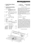
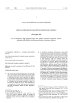
Prior Art Example
US Patent Number: 4,532,418 Date of Patent: Jul. 30, 1985
MICROPROCESSOR ELECTRIC VEHICLE CHARGING AND PARKING METER
SYSTEM STRUCTURE AND METHOD.
CARD
READER
OVERLOAD
DETECTOR
OPEN
CIRCUIT
KW
TRANSDUCER
DETECTOR
l
i‘ """""""""""" " ' '
PLUG
i
RANDOM
LOCK
;
ACCESS
MECHANISM
;
MEMORY
OPERATION
REQUEST
AND
DATA
TRANSFER
mm
I
' """ ‘ ' "
"
"""""""""""""""" ' “ “I
CENTRAL
__..
PROCESSOR
READ
.._..
UNIT
POWER
BREAKER
I
TIME
ONLY
;
MEMORY
i
NUMBRIC
DISPLAY
CLOCK
GPERATIONAL
DISPLAY
TIME
IN USE
KWHR
COST
OUT OF ORDER
VIOLATION
REJECT
IMPROPER
CHARGE CARD
Patent Application Publication
Sep. 23, 2010 Sheet 2 0f 5
US 2010/0241542 A1
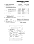
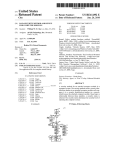
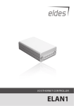
FIG. 2 Vehicle Identi?cation System Functional Diagram
.
_
n
s
_
_
c
em
.N
n
.
“in.
G
u
m
Y
..
o
_IS
.
_
_
.
_
.
m
E
m
.0"
"
_._T.
.m
m
“E
mm
m
.
u
H
w
m
u
B m
u
“E
9%
“S._ai ni
w
"
.M"
.osm
n
.eC
S
m
m
mm
m
_
mm"
.1
n
m
0
..
_
.0.
_I.
L..-Hn1_.
.m
"m.
.Mm.
m
L
m
3%
mu
.-N
.
mm
mmM
pg_.
n
.
m
“a
u
m
n
v
m
“M
mm
.
u
n
u
n
.m
n
m
HQ?
m
\
.
n
Dm
i.L__M_ w
&
n
M...
.
“m;
.
u
o
u
m
i.
R
G
\
Kw.
.
n
Q
u
0c
_.
\
S
n
._.~.3..
\_
_9..
.m.
Ow
m
n
.w"
t_
_
.
.
_
M
.Re.
DSn
.m
_S..n._
n
Ml
D
Q.
S
.
.
_
__
mum
m
m
m
n
u
ma
Mm
.
.n
_1R
._
mm.
R
mm.
.
n
.
n
“m.
m
_
n
u
.
H
.
n
1E
_u
.
I1J
L
u
N
n
“T.
..lr.
m
"mm.
H.
mm"
m
um
m
0
m __.ff.._
R
L.
_
.
_
.
.
m
m.5
nN.w
Lnl l l
\m
u
"Iv.
.
n
.
0
.N
Mm
.
.
w
n
u
.
u
E
u
.00.
n
._
C
M.
n
_H
0E
mm_
ma
m
n
.
n
0
.
mm
MA
.
.
_.
n
u
n
n
.
n
u
u
u
u
n
n
n
u
n
u
.
n
n
n
.
n
.
_
.
_
.
_
.
u
n
n
n
.
n
.
_
. _
_
n
n
_
.5.
.
n
-_
POWER CONTROLLER! ENERGY METER
REMOTE
ID
DEVICE
Patent Application Publication
H1;
Sep. 23, 2010 Sheet 3 0f 5
gianéwwa fiwahaméng ii-tatian 85%1»: magma}
US 2010/0241542 A1
Patent Application Publication
Sep. 23, 2010 Sheet 4 0f 5
US 2010/0241542 A1
Patent Application Publication
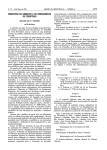
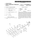
Fig.5
Sep. 23, 2010 Sheet 5 0f 5
US 2010/0241542 A1
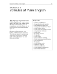
Vehicle ID Device Block Diagram
ID DEVICE
COMMUNICATOR
\
p
3
\ 21
a
r
i1) STORAGE
S
\
3I’
f
c
/ a
25
/
\
22
\\
23
.
I [DEXPIRATOR
Sep. 23, 2010
US 2010/0241542 A1
VEHICLE IDENTIFICATION SYSTEM,
METHOD AND RECHARGING STATION FOR
ELECTRIC VEHICLES
BACKGROUND OF THE INVENTION
[0001]
1. Field of Invention
[0002] The present invention relates to battery recharging
system for electric and hybrid electric vehicle. More speci?
cally it relates to the vehicle identi?cation used in an electric
vehicles recharging station.
[0003] 2. Description of PriorArt
[0004] Periodic charging of electric vehicles is a necessity.
Public recharging facilities and poWer stations in garages and
parking places, such as garages of apartment buildings and
shopping mall parking facilities, are not currently available.
This problem severely limits the realistic use of electric auto
mobiles.
SUMMARY OF THE INVENTION
[0013]
The solution for above issues is to associate the
authorization for electric energy usage With a vehicle that
receives such energy for recharging. Present invention
resolves the above-mentioned issues by implementing a
vehicle identi?cation system.
[0014]
The presented vehicle identi?cation system and
method enable a recharging station to identify an electric
vehicle connected to it for recharging, and resume recharging
after any recharging interrupt.
[0015] It is understood that recharging authorization is
essential for keeping track of energy usage and receiving an
appropriate payment for the amount of electric energy used in
recharging and for other services, Which may include parking
and any other associated sales.
[001 6] The variety of billing/payment arrangements, Which
Unlike conventional fuel operated vehicles Which
can be implemented in electric vehicle recharging, is beyond
the scope of the present invention and omitted for clarity.
can be refueled in minutes, it takes hours to recharge electric
automobile batteries. It is unlikely that a garage attendant or
a vehicle operator stays With the vehicle throughout the entire
any other type of vehicle that use an external source of electric
energy for recharging its batteries is referred to as a “vehicle”,
[0005]
recharging process. That opens possibilities for energy theft.
[0006] In an attended parking facility the garage personnel
may need to disconnect a car from the recharging station and
move it around. Then the car should be connected to the same
or to another station to continue recharging.
[0007] Severe poWer outages can occur during the charging
period. They may also create a problem in recharging con
tinuation due to expired authorization.
[0008] There is a need for a reliable method to prevent
energy theft in recharging facilities. There is also a need for
automatic continuation of the recharging process after any
recharging interrupt, so that no manual authorization of
recharging after such interrupt Would be necessary.
[0009] Solutions available in the prior art do not address
these issues.
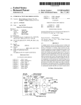
[0010] The US. Pat. No. 4,532,418 to Meese offers using a
mechanical lock to prevent disconnecting an electric car from
[0017]
the recharging station is referred to as a “station”, identi?ca
tion as “ID”, and any event of the recharging interrupt due to
either poWer outage or disconnection and subsequent recon
nection of the charging cable is referred to as a “recharging
interrupt”.
BRIEF DESCRIPTION OF THE DRAWINGS
[0018] FIG. liPrior art example, shoWs US. Pat. No.
4,532,418 diagram of recharging structure With a lock mecha
nism on recharging cable plug. FIG. 2iVehicle Identi?ca
tion system functional diagram
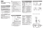
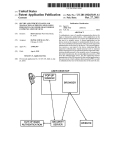
[0019] FIG. 3iStand-alone recharging station block dia
gram
[0020]
recharging during a parking period the valid charge card
should be manually “inserted for the second time”, Which is
impossible if the card oWner or an attendant are not present. In
the event of poWer interruption in a large public parking
facility this invention does not provide a convenient solution
to continue recharging When poWer is restored.
[0011] The US. Pat. No. 6,081,205 to Williams teaches to
use time meters for energy charges. In this invention recharg
ing is going on during certain paid time. Such method also
cannot prevent electric energy theft in a public garage if any
unauthorized car is connected and recharged instead of the car
that is billed for the energy usage.
[0012] It is an objective of this invention to provide a reli
able method to facilitate automatic continuation of the
recharging process Without authorization of the vehicle
operator or a garage attendant after interrupt in recharging for
FIG. 4iNetWork of recharging stations block dia
gram
[0021]
a recharging station until recharging is complete, as shoWn in
FIG. 1 While this solution prevents energy theft it creates a
problem When there is a need to move the vehicle around.
That can be unsafe in emergency situations. The same patent
discloses a charging station With the card reader and a sepa
rate charge card that may be obtained through a local poWer
company or from the operator of a parking facility, such as
shopping malls and garages. In case of any termination of
Hereinafter, an electric or electric hybrid vehicle or
FIG. 5iVehicle ID device block diagram
DESCRIPTION OF THE PREFERRED
EMBODIMENT
[0022]
The description of the preferred embodiment is
intended for illustration and not for limitation purposes, and it
is understood that those skilled in art can ?nd different imple
mentations of this invention Without departing from the scope
and spirit of the invention.
[0023] In the most basic form of the preferred embodiment,
the vehicle is equipped With a unique key, and the station is
equipped With a reader to receive identi?cation information
from this key. Every time a vehicle is connected to a recharg
ing station, the recharging station obtains ID information
from the key and, if this ID is recognized as previously asso
ciated With valid authorization, the recharging process
resumes. If the ID is not recognized the recharging station
requests a payment or any other form of recharging authori
zation. When authorization received, the vehicle ID is stored
by the recharging station in association With this authoriza
tion.
[0024] The key may be provided in a form of a mechanical
key, any form of a magnetic or optical media, or an electronic
device communicating to the reader through Wires or Wire
lessly.
preventing energy theft and promoting safety in public
[0025]
garages and parking facilities.
or using electromagnetic Waves, it is preferred to use short
When using Wireless communication either optical
Sep. 23, 2010
US 2010/0241542 A1
distance communication devices to ensure that the ID is
received from the same vehicle that is connected to the sta
[0042] Recharging Error
[0043] Safety system calls (short circuit, ground fault,
tion. E.g. if an RFID (Radio Frequency Identi?cation Device)
chip is used, it should be located either in the vehicle’s charg
ing plug or in a separate enclosure (a tag) attached to it, and
the reader of the station should be placed accordingly.
[0026] Wired communication may be achieved through
[0044]
[0045]
extra contacts on the charging plug or through the main poWer
conductors of the charging cable by using any form of a poWer
line communication (PLC).
[0027] A non-electronic key is simply read by the reader,
and the ID information is stored by the station until the charg
ing is complete, or for a predetermined period of time, if
interrupted.
[0028]
An electronic key may communicate the ID infor
mation to the reader on its oWn, eg when ?rst connected to
the station and then every, say, 30 seconds. Alternatively, it
may communicate the ID in response to a query from the
reader, Which in this case may be referred to as an interroga
tor.
[0029] An electronic key, Which may also be referred to as
an electronic “ID device”, may use either prerecorded ?xed
overvoltage, overcurrent, etc)
[0046]
Battery Is Full
STOP button pressed
The Vehicle Identi?cation logical module 50 com
prises an ID Requestor 10, ID Generator 11, ID Storage 12, ID
Comparator 14, ID Validator 19, and a Communicator 13,
Which communicates through the communication link 16
With a Remote ID Device 15.
[0047] A Billing logical module 17 associates an ID
received from the Vehicle Identi?cation module 50 With the
electric energy usage from a PoWer Controller/Energy Meter
18 and a current time stamp, and provides a PoWer On/PoWer
Off command to the PoWer Controller/ Energy Meter 18,
Which responds to the command by turning the poWer on or
off at the vehicle recharging cable.
[0048] When a recharging cable plug connects With a
recharging station receptacle or When the poWer is restored
after an outage the System Events module 51 generates a Start
System request to the ID Requestor 10. The ID Requestor 10
neW charging cycle is initiated. The ID information may
sends the ID request to the Remote ID Device 15, located in
the vehicle or attached to the vehicle, using Communicator 13
include any relevant data regarding charging requirements,
via the communication link 16. In this particular example the
such as recommended charging mode, a current battery
communicator comprises a PLC modem and the communi
cation link is a conductor of the charging cable.
[0049] If the vehicle has been previously connected to a
station and the Remote ID Device 15 still carries a valid (not
ID information, or generate neW ID information every time a
charge level, vehicle or battery model, etc.
[0030] Alternatively, the ID may be generated and assigned
to the vehicle by the station upon charge initialiZation, and
then requested back periodically, or after the recharging inter
rupt. In this case, the assigned ID is stored by the vehicle’s ID
device. The assigned ID may contain a time stamp, a station
ID, a requested or prepaid amount of energy, and any other
relevant information. Regardless of the origin of the ID infor
mation, it should not uncontrollably change during the entire
recharging period, even With recharging interrupts, until it
expires after a predetermined time period or the recharging is
complete.
[0031] The folloWing detailed description of the preferred
embodiment demonstrates a use of an electronic ID device
expired) ID, this device sends the ID back to the Communi
cator 13 through the communication link 16. The Communi
cator 13 sends the received ID to the ID Comparator 14,
Which compares it to every ID found in the ID Storage 12. If
a match is found, the ID Comparator 14 sends this ID to the
Billing module 17 to ensure that the energy usage for recharg
ing is added to the previous charges associated With this ID.
Then the Billing module 17 generates a PoWer On command
for the PoWer Controller/Energy Meter 18, Which in turn
sWitches on electric current from the poWer source via the
With ID assigned to it by a recharging station. The poWer line
recharging cable to the vehicle battery and recharging process
communication (PLC) is used for information exchange
resumes. The electric energy used for recharging is recorded
in the Billing module 17 Where it is also associated With a
vehicle ID.
[0050] If the ID match is not found, the ID Comparator 14
sends a request to the Service Authorization module 52 to
provide an authorization. When the authoriZation is provided
(eg in a form of a payment, a charge card, a ticket read, etc.),
the module 52 sends a request to the ID Generator 11 to
generate a neW ID. When generated, the neW unique ID is
betWeen a station and a remote ID device. While the folloWing
description assumes a charging cable attached to the vehicle
plugging into a receptacle located in the recharging station, it
stays valid, With the appropriate adjustments, for a situation,
When the charging cable permanently attached to the recharg
ing station gets plugged into a recharging receptacle located
on the vehicle, and for any possible variations in betWeen.
[0032] A functional diagram on FIG. 2 illustrates the
Vehicle Identi?cation System implemented in this embodi
ment.
stored in the ID Storage 12, transferred to the Billing Module
to certain external and internal system events, generates
17, and communicated to the Remote ID Device 15 via the
Communicator 13 and the communication link 16. This neW
ID Will be stored in the Remote ID Device 15 until it is deleted
requests to start system or to stop recharging for a Vehicle
by the recharging station or expires after a predetermined
[0033]
The System Events logical module 51, in response
Identi?cation logical module 50.
[0034] The folloWing events may trigger the Start System
request:
[0035] Recharging Cable Connected
[0036]
[0037]
[0038]
PoWer Restored
Service AuthoriZed
Ticket Number Obtained
[0039] The folloWing events may trigger the Stop Recharg
ing request:
[0040] Recharging Cable Disconnected
[0041]
Loss of PoWer in the PoWer Source Circuit
period of time (say 12 hours).
[0051]
If no ID is received from ID Device the Communi
cator 13 sends a ‘No ID’ message to the ServiceAuthoriZation
module 52, and then the sequence of events described in the
‘ID match not found’ case above is repeated. This Way, if the
connected for recharging vehicle does not have a Remote ID
Device installed, the system Will require authoriZation every
time it is connected, Which ensures full compatibility of any
vehicle With the recharging station.
[0052] At any moment When the requested service autho
riZation is not received, the system goes into a Waiting mode.
Sep. 23, 2010
US 2010/0241542 A1
[0053] The recharging is considered completed When the
client recharging service request set during service authori
zation is satis?ed. Such client request may include recharging
until the battery is full or the speci?c amount of recharging
energy expressed either in time units, or energy units (or any
other units) or the amount of prepayment for the service.
[0054]
The Battery Full event triggers a “Stop Recharging”
request from the Systems Events module 51 to the ID Vali
dator 19 of the Vehicle Identi?cation module 50. The ID
Validator 19 sends the current ID to the Billing module 17 to
close the sale associated With this ID and generates a com
mand ‘Delete ID’ to the Remote ID Device 15, and also
deletes this ID from the ID Storage 12.
[0055] When a request for a speci?c amount of energy (or
payment) is ful?lled, the Billing Module 17 closes the sale
associated With this ID and sends a message ‘Recharging
Complete’ to the ID Validator 19, Which generates a com
mand ‘Delete ID’ to the Remote ID Device 15, and also
deletes this ID from the ID Storage 12.
or Without parking attendants, With a prepayment or a pay
ment at garage exit, With billing by garage authority or by
electric utility company.
[0061] An ID Device located Within the vehicle or built-in
into the vehicle’s charging cable can communicate via such
cable to a recharging station. Referring to FIG. 5, the ID
device includes an ID Storage 22 for storing vehicle elec
tronic ID and a Communicator 21 for communicating With
the charging station. The ID Storage 22 is preferably a non
volatile memory type, so that the loss of poWer does not affect
the stored ID. The Communicator 21 is needed for receiving
an ID generated and sent by a recharging station, as Well as
receiving requests from a recharging station to submit the
stored ID, sending the stored ID back to the station and
deleting that stored ID on the station request. The ID Device
may store a number of different IDs received from various
stations. In case the vehicle gets disconnected prior to the end
of the recharging period, an optional ID Expirator 23 is
included to delete a stored ID after a predetermined period of
time. Alternatively a FIFO (?rst-in-?rst-out) memory may be
[0056] If a Stop button (not shoWn) is pressed before the
completion of the recharging process, the System Events
to the device memory capacity.
module 51 sends a command ‘Stop Recharging’ to the ID
Validator 19, Which generates a command ‘Delete ID’ to the
Remote ID Device 15, and also deletes this ID from the ID
Storage 12. The ID Validator 19 also sends an “ID to Close
Sale” message to the Billing 17, Which closes the sale for this
ID.
[0062] A Stand-alone Recharging Station using the pro
posed vehicle identi?cation method may be built according to
the block diagram of FIG. 3. Here, the Processor 1, compris
ing a microcontroller With on-board memory, represents the
core of the system. Referring to FIG. 2, the Processor 1
implements the ID Generator 11, ID Storage 12, ID Validator
[0057]
19, ID Comparator 14, ServiceAuthorization module 52, and
Billing module 17.
[0063] The Manual Input Device 2 comprises a number of
pushbuttons (or equivalent user entry devices, eg touch
screen buttons) for user selection (eg 20 kWHr, 4 Hrs, $10,
$20, full battery ?ll up, or other similar buttons de?ning
If the vehicle is unplugged prior to completion of
recharging, the system disconnects the poWer and goes into a
Ready mode, Waiting for the cable plug-in.
[0058]
The IDValidator 19 periodically checks time stamps
of all the IDs stored in the ID Storage 12. An ID is considered
expired after a predetermined period of time from the last use.
If an expired ID is found, the ID Validator 19 deletes the
expired ID from the ID Storage 12 and sends an “ID to Close
Sale” message to the Billing 17, Which closes all the sales
associated With this ID.
[0059] As folloWs from the description above, a service
authorization is necessary in order to start recharging. Gen
erally, an authorization to get services is the association of the
vehicle With the amount and/or method of payment for these
services selected by a client. To authorize recharging a client
may use cash payment, credit card payment, or any media
issued by a garage authority, such as a plastic card With a
magnetic strip, a plastic card With a memory chip, a plug-in
into the station key-chain device and other methods, Where
the client account information is encoded on the media. The
station may accept one of the above authorization methods to
authorize recharging from a stand-alone station or a netWork
station in an attended garage, hoWever the familiar paper
ticket procedure can also be used. A service authorization
With paper ticket can be implemented as a reading of the
unique number from a ticket bar code scanned in the station
bar-code reader. Such paper ticket may contain up to 3 parts
With the same bar code. One part of the ticket is for keeping in
the garage o?ice, another part is for the client and the 3”‘ part
is for scanning it in the station and keeping in the vehicle or by
attendant. Other variants of a vehicle service authorization
can also be implemented.
[0060]
There are different payment and billing scenarios,
Which could be described, but omitted here because they are
not directly related to the present invention. Such scenarios
include a service authorization in some form: in garages With
used for ID Storage, so that the most recent IDs are stored up
recharging duration). This device also includes a Cancel but
ton to cancel an entry, and a Stop button, to manually stop
recharging at any moment prior to completion.
[0064] A Display 6, comprising a number of indicators
and/or a visual device (LED, LCD screen, and such), and
connected to the Processor 1 communicates the system mes
sages to the user.
[0065]
A Payment Receptor 3 may include a cash receptor,
a credit card reader, a barcode reader, and any other device
capable of reading an appropriate authorization media. It may
also include a receipt printer. The Payment Receptor 3 is a
part of the Service Authorization module 52.
[0066] A Vehicle Identi?er Module 4 implements the ID
Requestor 10 and the Communicator 13.
[0067]
A Cable Connector 5 connects to a vehicle recharg
ing cable to supply recharging energy from the PoWer Con
troller 7 to the vehicle. It also interfaces the Vehicle Identi?
cation Module 4 to the Recharging Cable 16 for
communication With the Remote ID Device 15. The Cable
Connector 5 is equipped With a detector sWitch to detect When
the recharging cable 16 is connected and disconnected. This
sWitch along With the buttons of the Manual Input Device 2
comprises a System Events module 51.
[0068] The PoWer Controller 7 implements the PoWer Con
troller/Energy Meter module 18 that connects and discon
nects poWer from the recharging PoWer Source 8 to the Cable
Connector 5, based on commands received from the Proces
sor 1. The PoWer Controller also communicates the Energy
Meter readings to the Processor 1 for billing. The PoWer
Controller 7 comprises a poWer ON/OFF SWitch, an Energy
Sep. 23, 2010
US 2010/0241542 A1
Meter and Protection Circuitry. It may also provide control of
the recharging parameters, such as recharging current, volt
age, etc.
[0069] A Network of Recharging Stations may be imple
mented for large parking and garage facilities. Network
implementation is especially effective for facilities with
attendants or valet parking. An example of such implemen
tation is shown on a block diagram of FIG. 4. This example
assumes an attended facility with multiple entrances and
exits. A standard three-part paper ticket processing is selected
for compatibility with existing parking facilities practice.
[0070]
The network of recharging stations comprises a
Central Unit, a number of Recharging Stations, and a number
of Payment Stations interconnected in a network.
[0071] Recharging Stations in a network include a Network
Interface Device 101 to enable network communication, and
substitute the Payment Receptor 3 with a Ticket Reader 9. The
Processor 1 no longer implements the ID handling and stor
will be used in the service authorization process. For any
vehicle entering the parking a new three-part paper ticket is
issued. All ticket parts carry the same unique bar-coded num
ber. A facility operator or an attendant gives one part of that
ticket to a client, keeps another part of the ticket in the of?ce,
and uses the third part for vehicle authorization at the recharg
ing station.
[0078]
After moving the car to any recharging station the
attendant connects a recharging cable to the station’s connec
tor and the station generates a request for vehicle ID to be sent
to the vehicle’s remote ID Device.
[0079] If the recharging station receives a vehicle ID in
response to said request then the station sends this ID to the
Central Unit’s CVI module for identi?cation. If the ID is
recognized there as previously authorized, the Central Unit
sends a command to the station to resume recharging.
[0080] If the station does not receive any ID from the con
nected vehicle remote ID Device, or if the received ID is not
age functions, billing and authorization.
[0072] These functions (ID Generator 11, ID Comparator
14, ID Validator 19, ID Storage 12, Billing 17, and Service
recognized by CVI as previously authorized then the station
Authorization 52) are implemented in a Central Unit, which
may be located in a central o?ice of the facility. The Central
Unit comprises a Processor 30, which controls operation of
the entire network, a Manual Input Device 32 for user manual
a new ID and links this new ID to the obtained ticket number.
data input, a Ticket Reader 35 for reading a number from a
parking ticket, a Display 36 for showing visual information to
the user, a Central Vehicle Identi?er (CVI) module 33 for
identi?cation of a vehicle connected to any station on the
network and a Central Billing Module 34 (CBM) for central
billing and payment processing. Both CVI and CBM can be
displays a request to scan a ticket. The attendant then scans
the ticket and the station receives the ticket number, generates
Then the request for authorization data associated with this
ticket number is sent to CBM. Such authorization data can
include authorized by the vehicle operator amount of energy
to be used in recharging or the recharging time, or the recharg
ing capacity, or the amount of payment, and/or method of
payment. Authorization data and the ticket number may be
entered at the vehicle entrance into the garage. If the autho
rization data has already been associated with the ticket num
ber and stored in CMB, then, in response to the recharging
implemented as software or hardware modules. CVI here
station request, it is sent back to the station to de?ne normal
further comprises a central ID Storage 37 (CIS) for storage of
completion of the recharging process. Otherwise, the atten
dant using Manual Input device of the recharging station
enters the data authorized by vehicle operator (e. g. recharging
any ID generated by any station on the network and a central
ID Comparator 38 (CIC) for comparing incoming vehicle ID
with ID stored in CIS. This variant of CVI implements the
energy in kWHr, recharging time, recharging battery capac
idea that new IDs are generated and deleted by a Vehicle
ity, amount and method of payment or other data that may
Identi?er module of a station connected to a vehicle and not
defy recharging duration). Such authorization data together
by the central unit CVI. The Central Unit is connected to the
with the ticket number and generated new ID are linked
network with a Network Interface Device.
together. The newly generated ID is sent to the vehicle’s
[0073] Another variant of CVI can be also implemented,
where in addition to CIS and CIC the following modules can
remote ID Device, as well as to the Central ID Storage of CVI
be included: a central ID Generator for generating new IDs, a
for billing. After that the recharging begins.
[0081] When the recharging is successfully completed or
central ID Validator for deleting expired IDs and deleting IDs
on the recharging complete and the sale closed events. This
variant of the CVI re?ects the idea that a central vehicle
identi?cation module will generate, store, assign and delete
all IDs in the network.
[0074] The Payment Station in the FIG. 4 comprises a Pro
cessor 40, a Display 46 for providing visual information to the
user; a Manual Input Device 42 for selecting the amount of
energy for recharging and other tasks that require manual
input; a Payment Receptor 43, such as a cash receptor, credit
card reader, charge card reader or any other payment or billing
authorization card reader to pay for services; a ticket reader
for reading a ticket that linked to the services provided to a
vehicle.
[0075]
Other variants of implementation of the network of
recharging stations are certainly possible and implied by this
invention.
[0076] Following is the example of network operation,
while it is understood that other scenarios are possible with
out deviating from the scope of the present invention.
[0077] Upon entering a parking facility a client or a vehicle
operator communicates to parking personnel a desired
amount of recharging energy, or recharging time, or payment
for recharging, or full battery ?ll-up. This authorization data
for further reference and to Central Billing Module (CBM)
stopped by pressing a Stop button the amount of energy usage
together with vehicle ID are sent to CMB. Since recharging
process is ?nished, CMB sends a command to Central ID
Validator to delete this vehicle ID from the Central ID Storage
and also sends the Delete ID command to the recharging
station. The station in response of Delete ID command com
municates an instruction to delete this ID to the remote ID
Device of the connected vehicle.
[0082] Before leaving the facility a garage attendant or a
vehicle operator scans the vehicle ticket again. At that
moment all sales associated with this ticket in CBM become
closed, the vehicle ID that becomes deleted from any storage
on the network, if it has not been deleted before, and a com
bined bill for all services is generated. The vehicle is released
from the facility only after the payment is received or charged
to the client account by the Payment Station.
[0083] If the vehicle ID lifetime interval expires prior to
completion of recharging the ID Validator module of the CVI
deletes this ID from the Central ID Storage (CIS) and sends it
to the CBM for closing all sales associated with this ID. This
may happen if located in the garage a vehicle has not been
reconnected to any recharging station to complete recharging
after it was interrupted.
Sep. 23, 2010
US 2010/0241542 A1
[0084]
Similarly to the stand-alone station application, if
the ID cannot be deleted from a remote ID Device on request
then this ID Will expire after the ID lifetime interval and then
Will be deleted from ID device.
[0085] If a parking facility is operated the Way that a vehicle
may exit it before closing sales or before recharging is com
pleted then such parking facility should include a prepayment
or payment authoriZation before beginning of any services. If
a vehicle exits parking Without closing its sale then the
vehicle ID stored on the netWork Will expire after a prede?ned
ID lifetime interval and at that time all sales linked to this ID
become closed and bill is created, then the vehicle ID is
deleted from any storage on the netWork.
[0086] Here is another likely operational scenario for an
unattended parking facility.
[0087]
On entrance to the unattended parking facility a
client or a vehicle operator receives a ticket With a unique
bar-coded number. A vehicle operator ?nds the available
recharging station and connects the vehicle to it by the cable.
The sensor in the station’s cable connector generates a
Recharging Cable Connected event and the station displays a
request to scan the ticket, if a ticket has not already been
scanned. If the operator ?rst scans the ticket, the Ticket Num
ber Obtained event is generated and the station displays a
request to connect recharging cable. After both these opera
tions are completed by the vehicle’s operator the station dis
plays a request to select payment method and/or payment
amount, as it is common noW in gasoline stations.
[0088] If a client selects a prepayment amount and makes a
payment, then no other authoriZation is required to start
recharging. If a client has successfully authorized a credit
card charge or a client account charge, then further de?nition
of recharging duration is needed and the station displays a
request to enter either the amount of recharging energy,
recharging time or battery capacity to ?ll-up. That authoriza
tion data becomes associated With the ticket number and
stored in the Billing module. The station then generates the
ServiceAuthoriZed event that triggers Start System command
as in FIG. 2, Which in turn triggers ID Requestor and a request
for vehicle ID is sent to the connected vehicle. All other ID
related steps are described above.
[0089]
On exit of unattended parking facility if the credit
card or client account charge Was previously authoriZed the
vehicle operator must scan his ticket in the payment station
ticket reader to complete sales. At that moment, a bill is
created and the vehicle ID, Which Was stored in the recharging
station, in the remote ID device or in the central unit is deleted
from the netWork.
[0090] Other implementations of the vehicle ID method in
the netWork are certainly possible Without departing from the
scope and spirit of the invention.
1. The vehicle identi?cation system for electric vehicles
comprising:
an enclosure;
a vehicle identi?cation requesting means Within said
enclosure for creating a vehicle-identi?cation request;
a remote responding means positioned outside of said
enclosure for creating a vehicle identi?cation message
in response to said vehicle identi?cation request;
a communication means for communication betWeen said
vehicle identi?cation requesting means and said remote
responding means;
a message storage means positioned Within said enclosure
for storage and reference of the vehicle identi?cation
message;
a comparison means Within said enclosure for comparing a
vehicle identi?cation message With said vehicle identi
?cation message stored for reference and generating a
pass signal When both these messages identify the same
vehicle.
2. The vehicle identi?cation method for electric vehicles
comprising of:
generating a request for vehicle identi?cation by a vehicle
identi?cation requesting means;
communicating said request from vehicle identi?cation
requesting means to remote responding means;
creating a vehicle identi?cation message by a remote
responding means in response to said request;
communicating said vehicle identi?cation message from
remote responding means to vehicle identi?cation
requesting means;
storing a vehicle identi?cation message in the message
storage for further reference;
generating another request for vehicle identi?cation by the
vehicle identi?cation requesting means, When vehicle
identi?cation is required;
identifying a vehicle by comparing the received vehicle
identi?cation message With one stored as reference and
generating a pass signal if both these messages identify
the same vehicle.
3. The vehicle identi?cation system of claim 1 Wherein said
remote responding means further comprising of data input
means for creating a vehicle identi?cation message.
4. The vehicle identi?cation system of claim 1 Wherein said
communication means further comprising at least one Wire.
5. The vehicle identi?cation system of claim 1 Wherein said
communication means further comprising a Wireless trans
mitter and receiver.
6. The vehicle identi?cation system of claim 5 Wherein said
Wireless transmitter and receiver use electromagnetic Waves
for communication.
7. The vehicle identi?cation system of claim 5 Wherein said
Wireless transmitter and receiver use acoustic Waves for com
munication.
8. The vehicle identi?cation system of claim 5 Wherein said
Wireless transmitter and receiver use visible light for commu
nication.
9. A recharging station for electric vehicles comprising a
processor;
a display interconnected to the processor for giving visual
information to a user;
a manual input device interconnected to the processor for
enabling data input by user or service personnel;
a payment receptor for receiving payment for the electric
energy usage and other services, the payment receptor
interconnected to the processor for indicating receipt of
payment for recharging and other services;
a poWer source;
a connector for interconnecting the poWer source to the
electric vehicle;
a poWer controller interconnected betWeen the poWer
source and the connector and coupled to the processor,
the poWer controller selectively providing poWer to the
connector in response to commands from the processor,
the poWer controller further comprising an electric
poWer usage meter for measuring the amount of elec
tricity ?oWing therethrough;
a vehicle identi?cation requesting means for generating a
vehicle identi?cation request;
Sep. 23, 2010
US 2010/0241542 A1
a communication means interconnected to said vehicle
identi?cation requesting means for communication
betWeen the station and a vehicle identi?cation device;
a message storage means for storage and reference of the
vehicle identi?cation message received from the remote
identi?cation device;
a comparison means for comparing a received vehicle
identi?cation message With said vehicle identi?cation
message stored for reference and generating a pass sig
nal When both these messages identify the same vehicle;
said recharging station alloWing recharging of the electric
vehicle associated With said vehicle identi?cation
device in response to said pass signal.
10. A recharging station for electric vehicles comprising
a processor;
a display interconnected to the processor for giving visual
information to a user;
a manual input device interconnected to the processor for
enabling data input by user or service personnel;
a payment receptor for receiving payment for the electric
poWer usage and other services, the payment receptor
interconnected to the processor for indicating receipt of
message storage means positioned Within said enclosure
for storage and reference of the vehicle identi?cation
message;
comparison means Within said enclosure for comparing a
received vehicle identi?cation message With said
vehicle identi?cation message stored for reference and
generating a pass signal When both these messages iden
tify the same vehicle.
12. The vehicle identi?cation method for electric vehicles
comprising:
generating a unique vehicle identi?cation message by a
vehicle identi?cation generating means;
storing a vehicle identi?cation message in the message
storage for further reference;
communicating said vehicle identi?cation message to a
remote responding means;
storing the vehicle identi?cation message in the remote
responding means;
generating a request for vehicle identi?cation by a vehicle
identi?cation requesting means, When vehicle identi?
cation is required;
communicating said request from vehicle identi?cation
requesting means to remote responding means;
communicating said vehicle identi?cation message from
payment for recharging and other services;
remote responding means to vehicle identi?cation
requesting means in response to said request;
a poWer source;
a connector for interconnecting the poWer source to the
identifying a vehicle by comparing the received vehicle
identi?cation message With one stored as the reference
electric vehicle;
and generating a pass signal if both these messages
identify the same vehicle.
a poWer controller interconnected betWeen the poWer
source and the connector and coupled to the processor,
the poWer controller selectively providing poWer to the
13. A netWork for recharging electric vehicles comprising:
connector in response to commands from the processor,
the poWer controller further comprising an electric
poWer usage meter for measuring the amount of elec
at least one central unit for centralized authorization of
tricity ?oWing therethrough;
a vehicle identi?cation message generation means for cre
ating a vehicle identi?cation message;
a message storage means for storage and reference of said
vehicle identi?cation message;
a communication means interconnected to said vehicle
identi?cation requesting means for communication
betWeen said station and a vehicle identi?cation device;
a vehicle identi?cation requesting means for generating a
vehicle identi?cation request and receiving a vehicle
identi?cation message from a vehicle identi?cation
device;
a comparison means for comparing a received vehicle
identi?cation message With said vehicle identi?cation
message stored for reference and generating a pass sig
nal When both these messages identify the same vehicle;
said recharging station alloWing recharging of the electric
vehicle associated With said vehicle identi?cation
device in response to said pass signal.
11. The vehicle identi?cation system for electric vehicles
comprising:
an enclosure;
a vehicle identi?cation requesting means Within said
enclosure for creating a vehicle-identi?cation request;
a vehicle identi?cation message generation means for cre
ating a vehicle identi?cation message;
a remote responding means positioned outside of said
enclosure for storage of said vehicle identi?cation mes
sage and returning it in response to said vehicle identi
?cation request;
communication means for communication betWeen said
vehicle identi?cation requesting means and said remote
responding means;
electric vehicle recharging, billing and reporting;
and
at least one vehicle recharging station of claim 9.
14. A netWork for recharging electric vehicles comprising:
at least one central unit for centraliZed authoriZation of
electric vehicle recharging, billing and reporting;
and
at least one vehicle recharging station of claim 10.
15. An electric vehicle identi?cation device comprising:
a unique message generation means for generating a
vehicle identi?cation message;
a memory means for storing of at least one said vehicle
identi?cation message;
and
a communication means for communicating said message
to an electric vehicle recharging station.
16. An electric vehicle identi?cation device comprising:
a communication means for communicating a vehicle
identi?cation message to and from an electric vehicle
recharging station;
a memory means for storing of at least one said vehicle
identi?cation message;
and
an identi?cation message expiration means for removing
said identi?cation message from the memory means
after a predetermined period of time.
17. A netWork for recharging electric vehicles comprising:
at least one central unit for centraliZed authoriZation of
electric vehicle recharging, billing and reporting; the
central unit including at least some means necessary for
vehicle identi?cation, such as the means of claim 1 and
claim 16 for vehicle identi?cation message generation,
request, communication, storage, comparison and expi
ration;
and
at least one vehicle recharging station for electric vehicle
recharging; the recharging station including necessary
US 2010/0241542 A1
Sep. 23, 2010
7
vehicle identi?cation means not implemented in the Central
Unit for technological or other reasons;
processor for giving visual information to a user, a
manual input device interconnected to the processor for
18. A netWork for recharging electric vehicles comprising:
enabhng data lnput by 115? or Sen/Ice Personnel, a Pay
at least one Central unit ofclaim 17.
H t
h. 1
h .
t t.’
ment receptor for receiving payment for the electric
poWer usage and other services, the payment receptor
f 1 .
3 eas one Ve 16 e rec argmg S a Ion O C alm
17_
’
an
interconnected to the processor for indicating receipt of
payment for recharging and other services;
at least one payment station; a payment station further
comprising a processor, a display interconnected to the
*
*
*
*
*