1
USOO8760512B2
(12) United States Patent
(10) Patent No.:
Ogi et al.
(54)
(45) Date of Patent:
WIRELESS VIDEO TRANSMISSION DEVICE
2009/0195704 A1*
AND WIRELESS VIDEO RECEPTION
DEVICE
2009/0247085 A1*
2010/0118811 A1*
2010/0280671 A1*
(75) Inventors: Yuya Ogi, Yokohama (JP); Nobuaki
Kabuto, Kunitachi (JP)
Ltd., Tokyo (JP)
Notice:
Jun. 24, 2014
8/2009 Bombara .................... .. 348/734
10/2009
Misumi ..... ..
5/2010 Lee et al.
11/2010
.. 455/633
370/329
Lee ............................. .. 700/286
FOREIGN PATENT DOCUMENTS
(73) Assignee: Hitachi Consumer Electronics Co.,
(*)
US 8,760,512 B2
Subject to any disclaimer, the term of this
patent is extended or adjusted under 35
JP
JP
JP
JP
JP
7-303276
8-265823
2006-050521
2007-096462
2008-104100
11/1995
10/1996
2/2006
4/2007
5/2008
OTHER PUBLICATIONS
U.S.C. 154(b) by 345 days.
JP Of?ce Action for Japanese Application No. 2009-251597, issued
(21) App1.No.: 12/912,896
on May 21, 2013.
(22) Filed:
* cited by examiner
Oct. 27, 2010
(65)
Prior Publication Data
US 2011/0102589 A1
(30)
Primary Examiner * Dave Czekaj
Assistant Examiner * Nam Pham
May 5, 2011
(74) Attorney, Agent, or Firm *Antonelli, Terry, Stout &
Kraus, LLP.
Foreign Application Priority Data
Nov. 2, 2009
(JP) ............................... .. 2009-251597
Int. Cl.
H04N 9/47
(52) US. Cl.
(58)
(2006.01)
................................... .. 348/143; 348/E7.085
Field of Classi?cation Search
USPC
........................................................ .. 348/143
See application ?le for complete search history.
(56)
2006/0171343 A1
2007/0066329 A1
detected by the human body detector, a person detection
nal reception, thereby shortening the searching time cycle of
8/1998 Matsubara et al.
12/2005
to accelerate the start-up of the wireless video transmission
and reception devices. When the presence of a person is
signal is sent to a wireless video reception device or the
U.S. PATENT DOCUMENTS
2005/0281234 A1*
devices which intermittently perform signal reception pro
cessing within standby periods, a human body detection unit
transmission device to thereby limit usable communication
channel candidates in number. The limited number of usable
channel candidates are then used to perform intermittent sig
References Cited
5,799,241 A
ABSTRACT
A technique is provided for using, in a wireless video trans
mission device and a plurality of wireless video reception
(51)
USPC
(57)
Kawamura et a1. ......... .. 370/338
8/2006 Maehara et a1.
3/2007 Laroia et a1.
2007/0136772 A1*
6/2007 Weaver et al. ................ .. 725/95
2007/0171874 A1*
7/2007
2008/0022324 A1*
1/2008 Yang et al. .................... .. 725/81
Tanaka ....... ..
such intermittent reception within a standby period, thus less
ening the startup time from the standby state between the
wireless video transmission and reception devices and also
reducing standby power thereof.
.. 370/332
10 Claims, 7 Drawing Sheets
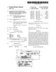
S101
PERSON SENSED'I
S106
PERSON SENSED?
Y
SEND CONTINUATION
COMMAND
S108
NORMAL STANDBY MODE I
US. Patent
Jun. 24, 2014
Sheet 1 017
US 8,760,512 B2
FIG.1
POWER OFF
:
V
~S1OO
S101
PERSON SENSED?
N
8102
SEND PERSON DETECTION
SIGNAL OVER Ch_N
Y
N
N=N+ 1
REPLY FOUND?
Q09
1 Y
7"
SPECIFIC STANDBY MODE
~S1Q4
Y
PREDETERMINED TIME
~ $105
MEASUREMENT
S106
PERSON SENSED?
N
>
8107
/
SEND CONTINUATION
COMMAND
S108
II
NORMAI. STANDBY MODE
A
REPLY FOUND?
/
US. Patent
Jun. 24, 2014
Sheet 2 0f 7
FIG .2
POWER OFF
~SZOO
NORMAL STANDBY MODE
~8201
PERSON
DETECTION SIGNAL
RECEIVED?
SEND REPLY COMMAND
~S203
_.._....._.___.___-—-->
V
SPECIFIC STANDBY MODE
~SZO4
I
PREDEFINED TIME
MEASUREMENT
“$205
CONTINUATION
CODE RECEIVED?
SEND REPLY COMMAND
~ $207
US 8,760,512 B2
US. Patent
Jun. 24, 2014
Sheet 3 0f7
US 8,760,512 B2
FIG.3
r
_
_
_
_
_
_
_
_
_
_
_
_
_
_
390
_
_
_
.
_
_
_
_
_
_
_
.
_
_
_...L:.._.1
I
301
l
r —
I
'
I
303
l
’J
'I
DVD
I
I
FLOW
,
'
l
3TB
HDMI I (TRANSMITTER)
'
RECORDER
:
R
304
— -
- — —
- —
~
(
I
I
I
I
i
I
l
T
MONITOR
l
— '-—4--1
MONITOR
'
DOWNWARD} (RECEIVER #1) (RECENER#2) {
HDMI I
HDD
—
I T
I
PLAYER
I
-’
|
I
I
(
Y 307 I
I
\
\-\
{ Y 306
I
\“
:
1
I
UvavéwRD I
302
I
MQNH'OR
AMP
I
:
1 (RECEIVER #0) (RECEIVER #4) 1
i
\
\-\
i
g
i
L
‘
g
‘
I
I
308
_
-
_
_
_
_
-
309 g
_
-
.
-
_
-
-
I
-_J
F IG.4A
+——T1
>4
T2
-
CHECK
CHECK
STARTUP I400
STARTUP
REQUEST
REQUEST
‘
‘
‘
‘
-
~
-
-
~
_
.
_
=
__
TIME
Ch Ch Ch Ch Ch Ch Ch Ch
Ch Ch Ch
12345678
X-2X-1X
_
TIME
FIG.4B
T3 T
401
401
401
401
401
g
‘“““*‘~'~1i~}§f_T‘I‘I'jfffj__________________________________ __
l<——T3—>\<——-———T4————>n
Ch Ch Ch
Ch Ch Ch
1
2
a
1
2
s
401
401
401
TIME
‘ ““ '
Ch Ch Ch
1
2
s
‘
US. Patent
Jun. 24, 2014
Sheet 4 0f7
US 8,760,512 B2
FIG.5A
T2
RADIOVIDEO
<—T1 >=
CHECK
V [490
TRANSMITTER
gg?ggg;
STANDBYOPERAT'ON
STARTUP
400
PROCESSING
\
;
\
500
;
501
502
USER
:
OPERATION
I
503
i
/
RADICVIDEC
RECEIVER
‘——~T5———>
505
,1
_
V
_
5
505
I
r/
STANDBY
STAHTUPREQUEST
3&5}?
STARTUP
OPERATION
SlGNAL(Ch1)
SIGNAUCM
PROCESSING
R
_
V
504
TIME
FIG.5B
T3
401
<44» /
RADIOVIDEO
TRANSMITTER
STANDBY
401
,J
STANDBY
OPERATION OPERATION
x
501
r/
STARTUP PROCESSNG
_
/
401
'
500
USER
OPERATION
502
503
RADIOVIDEO
RECEIVER
,
,
503 i f
\\
\
STANDBY
IIIIIIIIIIII
OPERATION
‘
I
506
~
sIIIIIII
/
'
STARTUPPROCESSNG
\R
a
507
504
_
'
“ME
US. Patent
Jun. 24, 2014
Sheet 5 017
US 8,760,512 B2
FIG .6
PERSON
DEFECTION
OUTPUT
0N
OFF
603
CHECK
RADIOVIDEO
RECEIVER
RADIOVIDEO
Q33 601
605
500
500
r/
r/
£602 SENDREPLYCOMMAND
500 500 500 500
'
STANDBY
OPERATION
/
c1
,1
5; ?g 55 $55
/
;\
4OOCHECKSTAFITUP
STANDBY
/
5% E2 2% E;
OPERATION
\
\
\\
_
\
'
;401 401 401 401 401
REQUEST
MODE
506 507 505 507 506
ggggfygq, $951,531, OPERATION OPERATION 0112111111011 _
STANDBY
TRANSMITTER
507
ISENDRRSON SQIBPERSCIP
r} /STANDBY
’J /STANDBY/
s11va
%@?§
666’
604
: STANDBYMODEAT SPECIFIC
NORMALSTANDBYMODE
: <
CHANNEL(Ch1,Ch2)
FIG.7
301
f1
10
11
/
12
/
IMAGEDISPLAY =
13
/
DSP
/
_
CPU
=
>
‘ 1
I
PERSON
I
16
7
i
MODEM = = TX/RX
14f
15
DR‘VER
'
17/
16/
DETECTOR
1
RC LIGHT
RECEIVER
US. Patent
Jun. 24, 2014
Sheet 6 0f7
US 8,760,512 B2
FIG.8A
<-~T1
:4
T2
=
CHECK
CHECK
STARTUP f 400
STARTUP
REQUEST
'
REQUEST
:
TIME
----------
<-
T1
- > Q l _
_ _ — _ “L
ChChChChChChChCh
ChChCh
12345678
X-2X-1X
_
TIME
FIGBB
T6 T7 ‘801
801
801
801
801
801
801
801
"““"I:Q~_~II:I‘I‘I'jffff__________________________________ __
T6->~<---—-T7
T_6——>_\“<————T7 ____________ "
Ch
3
802
/
803
TIME
Ch
4
802
803
802
803
US. Patent
Jun. 24, 2014
Sheet 7 0f7
US 8,760,512 B2
CHECK
CHECK
STARTUP r400
STARTUP
REQUEST
REQUEST
__
'
___________________ __
‘
T1
_____ ‘ 1
Ch Ch Ch Ch Ch Ch Ch Ch
1
2
s
4
5
e
7
>
TIME
Ch Ch Ch
8
K2 x-1
x
‘
TIME
CHECK
'C''HECK
STARTUP
REQUEST
5
___
CHECK
CHECK
STARTUP
STARTUP
STARTUP
REQUEST
REQUEST
REQUEST
‘ __________________ __
ll
T1
Ch Ch Ch Ch Ch Ch Ch Ch
1 2 3 4 5 6 7 8
>
TIME
_________ ‘ ‘2
Ch Ch Ch
K2 X-1 x
Tule
US 8,760,512 B2
1
2
WIRELESS VIDEO TRANSMISSION DEVICE
AND WIRELESS VIDEO RECEPTION
DEVICE
technique capable of speeding up the startup of a device(s)
and reducing electrical power consumption in standby events
in the case of performing intermittently the within-standby
period signal reception processing between a wireless video
INCORPORATION BY REFERENCE
of which is hereby incorporated by reference into this appli
transmission device and a wireless video reception device.
This invention provides a wireless video reception device
which receives a video signal that is wirelessly sent from a
wireless video transmission device. The wireless video recep
tion devices is arranged so that upon detection of the infor
cation.
mation as to the presence of a person, the number of those
The present application claims priority from Japanese
application JP2009-251597 ?led on Nov. 2, 2009, the content
communication channels usable for communication with the
BACKGROUND OF THE INVENTION
wireless video transmission device is reduced in such a man
ner as to be less than the number of communication channels
that are used before the detection.
The present invention relates to start-up acceleration tech
nology used in wireless data communications systems includ
ing a wireless video image transmission device and wireless
This invention also provides a wireless video transmission
device which wirelessly sends a video signal to a wireless
reception device which intermittently perform reception pro
cessing within standby periods, for making faster the startup
video reception device. This video transmission device is
arranged to have a ?rst standby mode which intermittently
procedure of these video transmission and reception devices
while simultaneously reducing electrical power consumption
20
in standby events.
Conventional known power-saving type wireless commu
nication techniques for causing a central control apparatus to
manage interconnection between radio terminals include a
standby control method which is recited in JP-A-7-303276,
for example. In this Japanese patent literature, there is dis
25
closed a technique adapted for use with a wireless communi
cation control scheme having a couple of radio terminal
devices which intermittently perform signal reception pro
cessing within standby periods. When a calling time point of
30
searches all communication channels to be used for wireless
communication between the wireless video transmission
device and the wireless video reception device in order to
check or verify a startup request from the wireless video
reception device and a second standby mode which intermit
tently searches communication channels that are limited than
those in the ?rst standby mode. In cases where a person exists,
transition is made to the second standby mode.
This invention also provides a wireless video transmission
device which wirelessly sends a video signal to a wireless
video reception device. This transmission device is arranged
a transmission-side radio terminal is not identical to the signal
to intermittently search for a communication channel to be
reception time of a reception-side radio terminal, a control
used for wireless communication between the wireless video
transmission device and the wireless video reception device
device which manages wireless communication between
these radio terminals noti?es the transmission-side radio ter
minal of the nearest signal reception time of the reception
in order to check a startup request from the wireless video
35
present, this search time cycle is made shorter.
This invention also provides a wireless video reception
device which receives a video signal that is wirelessly sent
side radio terminal . After the transmission- side radio terminal
that has received such notice noti?ed a calling connection
time to the control device, transition is made to a standby state
to thereby achieve steady connectivity and reduction of total
electric power consumption.
reception device in a standby mode. In a case a person is
40
Additionally, audio/video (AV) equipment power-saving
from a wireless video transmission device. This reception
device is arranged to force a radio unit’s power supply to turn
on in case a person is present while the radio unit power
techniques using a human-sensitive sensor include the one
supply of the wireless video reception device is turned off.
that is disclosed, for example, in JP-A-2007-96462. Dis
closed in this patent literature is a technique for reducing
power consumption of AV equipment by turning off the AV
equipment’s power supply when a predetermined length of
didates for use between the wireless video transmission
device and wireless video reception device are limited in
According to this invention, communication channel can
45
number or, alternatively, the time cycle of the search for a
time is elapsed after a user acted to go away from a nearby
communication channel is shortened when a person is
location of the AV equipment while letting the power supply
present, thereby making it possible to shorten the from
standby startup time of the wireless video transmission and
of AV equipment be kept operative.
50
SUMMARY OF INVENTION
Other objects, features and advantages of the invention will
become apparent from the following description of the
The above-stated prior art techniques are faced with prob
lems which follow. In JP-A-7-303276, use of the central
control device is required; also required is electrical power for
reception devices and also lessen the amount of electrical
power to be consumed during standby thereof.
embodiments of the invention taken in conjunction with the
55
accompanying drawings.
activating and rendering operative the central control device
BRIEF DESCRIPTION OF DRAWINGS
per se. Although it is possible to reduce total power consump
tion by applying the technique as taught therefrom to large
scale wireless communications of cellular phone base sta
tions or the like, there is a risk that it becomes unable to reduce
total power consumption in small-size networks, such as a
home-use one. As for JP-A-2007-96462, this fails to disclose
60
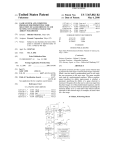
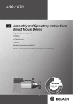
FIG. 1 is a ?ow chart of a processing operation of a device
having a human body detection unit in accordance with one
embodiment of this invention.
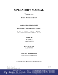
FIG. 2 is a ?owchart of a processing operation of a device
therein any teachings about the consumed power reduction
operatively associated with the device having the human body
using a human-sensitive sensor in the case of performing
wireless communications.
This invention has been made in view of the above-stated
detector unit in accordance with the embodiment.
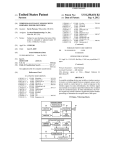
FIG. 3 is a block diagram showing one exemplary con?gu
ration of a wireless network which employs the embodiment
of this invention.
problems, and an object of the invention is to provide a
65
US 8,760,512 B2
3
4
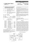
FIGS. 4A and 4B are pictorial diagrams showing a process
for veri?cation of a startup request in accordance with an
embodiment.
supplies this signal to an image display unit 10 provided in the
post stage. The image display unit 10 is constituted, for
example, from a liquid crystal display (LCD) or a plasma
display panel or the like for displaying video images based on
the signal from the DSP 11. Additionally, the header and
FIGS. 5A-5B are time charts of a startup sequence in
accordance with this embodiment.
FIG. 6 is a time chart of a standby mode transition opera
tion in accordance with the embodiment.
FIG. 7 is a diagram showing an exemplary con?guration of
a wireless video reception device in accordance with the
embodiment.
FIGS. 8A and 8B are pictorial diagrams showing a process
for veri?cation of a startup request in accordance with another
embodiment of the invention.
FIGS. 9A-9B are pictorial diagrams showing a process for
veri?cation of a startup request in accordance with a further
embodiment of the invention.
control command that are superimposed with the video/audio
signal are also demodulated by the modem unit 12 in a similar
way. The demodulated header and control command are sup
plied to a central processing unit (CPU) 14.
A human body detection unit 17 functions to detect the
information concerning the presence of a person or people,
which is driven and controlled by a drive unit 16 to detect and
determine whether a viewing person is present near or around
the radio video receiver device 306, 307, 308, 309, for
example (in particular, on the front side of the display plane of
the image display unit 10) and then supplies its detection
signal to the CPU 14. A remote control (RC) light receiving
unit 18 receives an RC signal from a remote controller (not
DETAILED DESCRIPTION OF EMBODIMENTS
depicted), which signal was generated by a user’s manual
Embodiments in accordance with this invention will be
20
described with reference to the accompanying drawings
analyzes the supplied header and control command and
inputs the detection signal from the human body detection
unit and the RC signal received by the RC light receiving unit
below.
Embodiment 1
25
300. This wireless network 300 includes a wireless or “radio”
30
35
internally perform the following operations: wirelessly send
body per se; for example, it may be arranged to indirectly
40
built-in signal source (not shown), other than wireless input of
45
illuminance sensor the fact that indoor brightness exceeds a
50
set-top box (STB) having a tuner for receiving TV broadcast
the monitor (receiver device #1) that is the radio video
receiver device 306, when he or she wants to switch the
55
ates the remote controller for use with the HDD recorder 304
to thereby send to the receiver device #1 a remote control
60
transmitter/receiver unit 13. This received video/audio signal
(RC) signal containing therein a control command for the
playback video change. The receiver device #1 optically
receives this RC signal and then wirelessly transmits the
control command signal to the radio video transmitter device
302 by way of the above-stated modem unit 12, transmitter/
is demodulated by a modulation/demodulation or “modem”
11. The digital signal processor (DSP) 11 applies image pro
presently reproduced video to another playback video that is
recorded in the HDD recorder 304, the user manually oper
transmitter device 302 is received through an antenna 15 and
cessing or else to the demodulated video signal and then
given threshold value.
In FIG. 3, in a case where the user is watching and listening
to a certain video reproduced from the HDD recorder 304 by
programs.
unit 12. The video/ audio signal that was demodulated by the
modem unit 12 is supplied to a digital signal processing unit
the radio video receiver device, is currently selected as an
external input in a state that the power supply of radio video
receiver device is turned on. Other examples include an
arrangement for indirectly detecting the presence or absence
of a viewer by detection of receipt of a certain kind of signal
by the RC light receiver unit 18 and/or by detecting using an
DVD player 303, HDD recorder 304, monitor, and ampli?er
An operation of the above-stated system will be explained
by also using FIG. 7 below. FIG. 7 shows an exemplary
con?guration of one of the radio video receiver devices 306
309 in accordance with this embodiment which is applied to
this system; here, it shows an example in which the radio
video receiver device is a monitor display. A video/audio
signal with which are superimposed a header and control
command to be wirelessly transferred from the radio video
detect the presence or absence of a viewing person by detec
tion of the fact that either a wire-connected signal source or a
interface (HDMI) cable. It is noted that in some cases, the
or else will be called the “AV equipment” hereinafter. Also
note that the radio video transmitter device 302 may be a
example, from either a human-sensitive sensor, such as an
infrared sensor, or an image pickup device, such as a camera,
which is attached to a location around the image display unit
10. The human body detector 17 is modi?able to have an
arrangement other than the one that directly detects a human
signal transmission cable. Examples of the equipment
include, but not limited to, a digital versatile disk (DVD)
player 303 and hard disk drive (HDD) recorder 304. An
example of the signal cable is a high-de?nition multimedia
a carrier for wireless transmission and then wirelessly sent
from the transmitter/receiver unit 13 to the radio video trans
mitter device 302 by way of the antenna 15.
Note that the human body detector unit 17 is the one that
detects and judges whether a viewing person is present near
the radio video receiver device and is constituted, for
ing video and audio signals from the radio video transmitter
device 302 to the radio video receiver device group 301, and
communicating a control command between the radio video
transmitter device 302 and radio video receiver device group
301. To the radio video transmitter device 302, equipment for
output of video and audio signals is wire-connected by a
to thereby generate a header and control command for con
trolling the radio video transmitter device. These header and
control command are modulated by the modem unit 12 using
FIG. 3 is a block diagram showing one example of the
con?guration of a wireless communication system in accor
dance with a ?rst embodiment of this invention. The illustra
tive wireless communication system has a wireless network
video transmission device 302 and a radio video reception
group 301 which includes a plurality of radio video receiver
devices 306 to 309, examples of which are a monitor, such as
television (TV) receiver set or else, an ampli?er for audio
output, and so forth. This wireless network 300 is arranged to
operation of a remote controller for the radio video receiver
device use, and supplies it to the CPU 14. The CPU 14
65
receiver unit 13 and antenna 15.
The control command which was wirelessly sent from the
radio video receiver device group 301 is received by a trans
mission/receiver unit via an antenna of the radio video trans
US 8,760,512 B2
5
6
mitter device 302; then, this control command is subjected to
kind/type analysis by a CPU within the radio video transmit
ter device 302. If the control command is for switching the
playback video of the HDD recorder 304 as stated previously,
to almost stop its operation (called the “standby operation”
hereinafter) while the startup request veri?cation 400 is not
performed, i.e., within a time period T2. In this way, the radio
video transmitter device is speci?cally arranged to repeatedly
perform the startup request veri?cation 400 and the standby
operation within its standby period. This will be called the
the CPU sends this command to the HDD recorder 304 via a
consumer electronics control (CEC) line of HDMI cable.
“normal standby mode” (?rst standby mode) hereinafter.
In this way, the wireless network 300 equipping the AV
equipment, the radio video transmitter device 302 and radio
video receiver device group 301 is constituted.
An explanation will be given below of one example of the
Next, one example of the startup sequence in the case of a
control command being sent from the radio video receiver
device 306 will be described with reference to FIG. 5A.
The radio video receiver device 306 also periodically
repeats execution of the startup request veri?cation 400 and a
processing (referred to as the “startup sequence” hereinafter)
of from the user’ s startup request in a standby or “wait” period
up to the actual transition to startup processing. Note here that
in the explanation below, a direction of signal transmission
from the radio video transmitter device 302 of FIG. 3 to the
radio video receiver group 301 is de?ned as the downward
?ow whereas the inverse direction thereof is de?ned as the
standby operation 503 within its standby time period in a
similar way to the radio video transmitter device 302. A time
cycle of the startup request veri?cation 400 and a time period
of the standby operation 503 in this radio video receiver
device 306 may be the same as a cycle T1+T2 of the startup
upward ?ow. More speci?cally, here, a video/ audio signal and
a control command of from the radio video transmitter device
to the radio video receiver group become the downward direc
tion; a control command of from the radio video receiver
device to radio video transmitter device becomes the upward
direction. Also note that the explanation below takes as an
example a startup sequence which begins from a speci?c
radio video receiver device 306, for purposes of brevity of
request veri?cation 400 and the period T1 of standby opera
20
At a given time point, when the user sends (as indicated by
502 in FIG. 5A) an RC signal which contains a control com
mand for activation of the radio video receiver device 306 to
the radio video receiver device 306, the radio video receiver
25
explanation.
video transmitter device within the period T5, the radio video
30
tains a control command for activation (e.g., power-on com
mand) toward the radio video receiver device 306. The radio
video receiver device 306 receives the light of this RC signal,
and wirelessly transfers this control command signal to the
35
45
such as electrical power feed to respective parts of the radio
video transmitter device 302, software program launching
and others.
In this wireless system, in order to enable the radio video
transmitter device 302 to receive the control command that
was wirelessly sent from the radio video receiver device 306,
it is necessary for the radio video transmitter device 302 to
recognize a communication channel to be used by the radio
video receiver device. To do this, within the standby time
period in which any video/audio signal is not being transmit
ted, the radio video transmitter device 302 searches, as shown
in FIGS. 4A and 4B for example, all available communication
channels in the wireless system (the total channel number is
denoted by “X”) within a time period T1 to thereby perform
veri?cation (indicated by numeral 400 in FIG. 4A) of a star
tup request for checking which one of the communication
channels is used by the radio video receiver device 306 to
send the control command. At this time, the radio video
50
and 506, respectively. In this way, the transmission of a star
tup request signal and the search for a usable communication
channel by veri?cation of a corresponding response there
from are sequentially performed with respect to those chan
nels of from ch1 up to ch21 under an assumption that the total
channel number X is 21. Hence, in case the channels ch1
ch20 are unusable because these have already been assigned
for communication with other devices, for example, the
above-stated transmission of startup request signal and the
veri?cation of its corresponding response have to be done
with respect to each of the channels ch1-ch20, thereby caus
ing a time taken for searching the communication channel to
increase in length, resulting in a decrease in response perfor
mance.
In the case of the above-stated one example of the startup
55
sequence, making longer and longer the standby operation
performing period T2 makes it possible to lower the electrical
power consumption within standby time period; however, this
60
transmitter device intermittently performs the startup request
veri?cation 400 within this standby period in order to sup
press power consumption in the standby period and retain it at
a low level, thereby forcing the radio video transmitter device
request signal (505). In case the radio video transmitter
device 302 performs the startup request veri?cation 400 and
searches the communication channel ch2 during transmission
of the startup request signal, this startup request signal that is
receiver device perform the startup processing operations 501
40
command is for startup as stated supra, the CPU of the radio
video transmitter device 302 performs startup processing,
receiver device 306 switches the channel ch1 to a communi
cation channel ch2 next thereto and then transmits a startup
the control command for activation from the radio video
receiver device is received using the communication channel
ch2; then, the radio video transmitter device and radio video
radio video transmitter device 302.
The control command that was wirelessly sent from the
radio video receiver device 306 is received by the transmis
sion/receiver unit via the antenna (not shown) of the radio
video transmitter device 302. This control command received
is passed to the CPU within the radio video transmitter device
302 and subjected to kind analysis thereby. If the control
device 306 ?rst uses a communication channel “ch1,” to
transmit a startup request signal 504 indicative of a control
command toward the radio video transmitter device within a
time period T5. In case no response is obtained from the radio
When the user wants to activate the radio video receiver
device 306 within a standby time period in which s/he is
watching no videos, the user manually operates a remote
controller for the radio video receiver device use (for
example, an operation of turning on a power button of the
remote controller) to thereby transmit an RC signal that con
tion 500 in the radio video transmitter device 302 or may be
different therefrom.
65
results in an increase in length of a time cycle for performing
the startup request veri?cation 400, which in turn leads to a
decrease in performance of responding to the user’s manual
operation. For example, in the time chart of FIG. 5A, when
letting T1:2 s, T2:8 s and T5:5 s, the startup processing gets
started after the elapse of about 10 s in maximum since the
user has completed his or her operation. This might give some
sort of uncomfortable feeling to the user.
Consequently, this embodiment is arranged to limit in
advance or “prelimit” (i.e., lessen) usable communication
US 8,760,512 B2
7
8
channel candidates in a case where the presence of a person is
An explanation will next be given, using a ?owchart of
FIG. 1, of the processing to be executed by the CPU 14 of the
radio video reception device for transition between the nor
detected on the radio video receiver device side, thereby
shortening the startup request veri?cation time and thus
accelerating or speeding up the activation processing. For
mal standby mode and the speci?c standby mode using the
example, as shown in FIG. 4B, in case the communication
channel candidates usable on the radio video receiver device
side are channels ch1-ch3, the startup request veri?cation is
not performed with respect to all available communication
channels but may be performed with respect to such channels
only within a time period T3 (401). For example, in case the
wireless system is arranged to have communication channels
whose number X is 21, when supposing that the number of
usable communication channel candidates is 3, it becomes
possible to perform the startup request veri?cation within a
time cycle that is shortened to one-seventh (1/7) while letting
human body detector unit 17 in this embodiment.
In a case where the radio video receiver device is powered
off (at step $100), the human body detector 17 detects the
information concerning the presence of a person for determi
nation of whether a person is present near the radio video
receiver device (at step $101). In case any person is absent,
transition is made to the normal standby mode (at $108). In
this normal standby mode, the startup request veri?cation
5
power consumption be kept almost the same as that in the case
of searching all available communication channels. In other
or, alternatively, may be synchronized with the intermittently
performed startup request veri?cation 507.
words, a speci?c arrangement is employed for prelimiting the
usable communication channel candidates in the case of a
person being detected by the radio video receiver devicei
that is, reducing the communication channels that are
which searches all communication channels is performed in
the way stated supra. Note here that the judgment of whether
a person is present or absent by means of the human body
detector 17 (at 8101) may be performed on an all-time basis
20
On the other hand, in case it is judged by the human body
detector 17 that a person is present, a person detection signal
is transmitted (at step $102) to the radio video transmitter
searched in the case of the person detection so that these are
less in number than those in the case of no person being
device over a communication channel ch_N. Then, a decision
sensedito thereby shorten the time cycle of the startup
request veri?cation. This mode of performing the startup
request veri?cation relating to these limited communication
channels will be called the “speci?c standby mode” (second
standby mode) in the description below. With this arrange
ment, it becomes possible to speed up the startup sequence of
is made (at $103) as to whether there is a reply command from
the radio video transmitter device with respect to the person
detection signal transmitted. Here, let the default value of N
be “1.” More speci?cally, the person detection signal is sent
the radio video transmitter device and radio video receiver
device while at the same time maintaining electric power
consumption at substantially the same level as that in the case
25
via the communication channel ch1 at ?rst. In case there is a
reply command from the radio video transmitter device, tran
30
of searching all communication channels.
Next, a startup sequence in the speci?c standby mode of
this embodiment will be described with reference to FIG. 5B.
35
In the speci?c standby mode, the radio video receiver
device 306 also repeats startup request veri?cation 507 and
standby operation 503 periodically in a similar manner to the
radio video transmitter device 302. A time cycle of the startup
request veri?cation 400 and a time period of the standby
operation 503 at the radio video receiver device 306 in the
speci?c standby mode may be the same as a time cycle T3+T4
of the startup request veri?cation 400 and a period T3 of
standby operation 500 at the radio video transmitter device
302 in the speci?c standby mode or, alternatively, may be
different therefrom.
At a certain time point, when the user sends (as indicated by
numeral 502 in FIG. SE) to the radio video receiver device
40
45
command, whether a person is present or absent is again
case no person is present, transition is made to the normal
standby mode (at $108). On the other hand, if a person is
50
device 306 uses a speci?c channel which is the candidate
55
channel ch1 during transmission of the startup request signal,
that is the control command for activation as sent from the
and receiver devices perform the startup processing opera
tions 501 and 506, respectively.
As stated above, in the speci?c standby mode in accor
dance with this embodiment, the time cycle for performing
the startup request veri?cation 401 in the startup sequence is
short; so, the performance of responding to the user’ s manual
operations improves accordingly.
present, a speci?c communication channel (e. g., the commu
nication channel that received the reply command from the
radio video transmitter device at 5103) is used to transmit (at
$107) to the radio video transmitter device a continuation
command for instructing it to continue the above-noted spe
ci?c standby mode, followed by judgment (at $111) as to
whether there is a reply command from the radio video trans
mitter device in response to this continuation command. If
there is such reply, the radio video receiver device per se
this channel ch1 is used to receive the startup request signal
radio video receiver device. Then, the radio video transmitter
procedure goes to step 8102 again; if it is larger than X then
transit to the normal standby mode.
After having transited to the speci?c standby mode, the
CPU 14 measures (at step $105) a time elapsed after having
received the reply command. In case a predetermined length
of time has been elapsed since the reception of the reply
judged (at step $106) by the human body detector unit 17. In
prelimited usable communication channel, e.g., channel ch1,
to transmit (504) a startup request signal for use as the control
command toward the radio video transmitter device 302. In
case the radio video transmitter device performs startup
request veri?cation 401 and searched the communication
Alternatively, in case there is not any reply command from the
radio video transmitter device, “1” is added (at $109) to the
value of the communication channel number N. Then, judg
ment is made (at $110) as to whether such value of N is less
than or equal to the total communication channel number X
(e.g., 21). In case the N value is less than or equal to X, the
306 an RC signal which contains a control command for
activation of the video receiver device 306, this video receiver
sition is done to the speci?c standby mode (at 8104), followed
by execution of the startup request veri?cation 507 which
searches limited communication channel candidates only.
60
continues the speci?c standby mode (at $104). If there is no
reply then transit to the normal standby mode (at $108).
Desirably, the reply command is arranged to contain
therein any one of the information for allowing the radio
video transmitter device and radio video receiver device to
limit the communicable channel candidates, information con
65
cerning the number of those equipments existing within a
communicable network, information about the length of a
time taken up to time-out of the speci?c standby mode, and a
US 8,760,512 B2
10
signal indicative of the fact that the radio video transmitter
device has received the command from the radio video
receiver device.
of N to thereby switch the communication channel to a chan
nel ch2 at step S109 of FIG. 1. Here, the total communication
channel number X is 21. The N’s value (i.e., 2) is less than or
The processing operations of the steps S102-S103 and
equal to X. Thus, the procedure returns to step S102 for
S109-S110 are also used for selection of the above-stated
sending the person detection signal again (as shown by “604”
usable communication channel candidates. Regarding this
selection, an explanation will be given later.
An explanation will now be given of the processing to be
executed by the CPU of the radio video transmitter device
in FIG. 6). In a similar way to the case of the channel ch1, the
radio video transmitter device receives (605) the person
detection signal from the radio video receiver device in the
process of intermittently performing the startup request veri
with reference to FIG. 2.
?cation 400, and decides a communication channel ch2 to be
the usable communication channel candidate, and then stores
the information of this channel ch2 in the storage unit. At this
time, “ch1” and “ch2” are to be stored in the storage unit as the
information of currently usable communication channels. In
In case the radio video transmitter device is powered off (at
step S200), control is provided to transit to the normal
standby mode (at step S201). In the normal standby mode, the
startup request veri?cation 400 which searches all the com
munication channels is performed in the way stated above.
The radio video transmitter device retains the normal standby
mode (at step S201) until it receives a person detection signal
case the number of such usable communication channel can
from the radio video receiver device (at S202). Upon receipt
of the person detection signal (at S202), it transmits (at S203)
the above-stated reply command with respect to this person
detection signal toward the radio video receiver device. After
the signal transmission, transition is made to the speci?c
20
standby mode (at S204), for performing the startup request
veri?cation 401 which searches currently usable communi
cation channel candidates only. Thereafter, the length of a
time is measured (at S205) which is taken since transmission
of the reply command. Then, judgment is made (S206) as to
whether the above-stated continuation command from the
received this reply command go into the speci?c standby
mode. Hence, in this example, the radio video transmitter
25
device is expected to search two communication channels
consisting of the channels ch1 and ch2 in the event of startup
request veri?cation in the speci?c standby mode.
In this way, those communication channel candidates
which are to be searched in the speci?c standby mode are
radio video receiver device is to be received within a time
period of from the transmission of the reply command up to
the elapse of a prespeci?ed time. When the continuation
command is received, the above-stated reply command is sent
(S207) to the radio video receiver device. In case it is unable
to receive the continuation command until a given length of
time elapses, transition is made to the normal standby mode
didates being saved in the storage unit reaches a prespeci?ed
number (in FIG. 6, the case of two channel candidates is
shown as an example), the radio video transmitter device
transmits (602) its reply command to the radio video receiver
device. The radio video transmitter device which has sent the
reply command and the radio video receiver device that has
30
selected. In the speci?c standby mode to which transition is
made when the presence of a person is detected, a reduced or
information of a time taken up to the time-out of the speci?c
“limited” number of communication channels are subjected
to the search, which number is less than the number of those
channels to be searched in the normal standby mode, i.e., the
total channel number.
The selection of communication channel candidates
should not exclusively be limited to the above-noted example
standby mode into the reply command or, alternatively, mul
and may be replaced, for example, by a method having the
35
(at S201). Note here that it is also permissible to multiplex the
tiplex the information of a continuation command transmis
sion time cycle in the person detection signal. To do this, it is
steps of presetting a plurality of communication channel can
40
desirable to set the prespeci?ed time used in the step S205 so
that this is longer than the predetermined time of the radio
video receiver device at step S105 shown in FIG. 1.
One example of the processing for selecting usable com
munication channel candidates in the speci?c standby mode
45
will next be described with reference to FIGS. 1 and 6.
In the normal standby mode, when an output of the human
body detector 17 of the radio video receiver device changed
from the OFF state (i.e., no-person detection state) to ON
state (person-detected state), the radio video receiver device
transmits (at step S102 of FIG. 1) the person detection signal
by using a communication channel ch_N (at ?rst, NII) as
using them in the speci?c standby mode.
As has been stated above, according to this embodiment, in
50
a case where the radio video receiver device detects the pres
ence of a person using the human body detector, usable com
munication channel candidates are reduced or limited in num
ber. This makes it possible to shorten the time cycle of the
intermittently performed startup request veri?cation without
having to increase the standby power, thereby enabling
indicated by numeral 603 in FIG. 6. The radio video trans
mitter device receives (601) the person detection signal from
the radio video receiver device in the process of performing
the startup request veri?cation 400 intermittently, and regards
didates (e.g., channels ch1 to ch3) and using them in the
speci?c standby mode. Another method may also be
employed which includes the steps of having searched in
advance and prestored, before the detection of a person by the
human body detector 17, those channel candidates (i.e., cur
rently unused or “idle” channels) usable for communication
between radio video receiver and transmitter devices, and
55
speed-up of the startup sequence. In addition, even when
once-limited communication channel candidates become
unusable due to a change in radio wave condition or else, it is
a communication channel ch1 as the channel usable for com
munication, and then stores the information of this commu
still possible, by transition to the normal standby mode in case
nication channel candidate in any one of a semiconductor
there is no reply command in response to a continuation
command, to prevent the occurrence of a mismatch in power
memory (not depicted) and an internal storage region of the
CPU of the radio video transmitter device (these will collec
tively be called the “storage unit” hereinafter). Then, at step
60
S103 of FIG. 1, the radio video receiver device determines
whether there is a reply command from the radio video trans
mitter device. In the example of FIG. 6, the radio video
receiver device receives no such reply command from the
radio video transmitter device so that “l” is added to the value
65
supply condition between the radio video receiver device and
the radio video transmitter device.
Although in this embodiment one illustrative example with
the human body detector 17 being attached to the radio video
receiver device was shown, this detector may be attached to
the radio video transmitter device. It would readily occur to
those skilled in the art that this embodiment is also applicable
US 8,760,512 B2
11
12
in a similar way even in cases where the radio video receiver
nel candidate number is 2. Assume that the number of com
and transmitter devices are interchanged in function with
each other.
munication channels to be assigned within the second period
803 is 1. In this case, the startup request veri?cation 801 is
Embodiment 2
nels in the following order:
1, 2, 3, Standby (T7), 1, 2, 4, Standby (T7), 1, 2, 5, . . ..
Desirably, the above-stated cycle of the startup request veri
performed in such a way as to search communication chan
A second embodiment of this invention will be explained
using FIGS. 8A and 8B below. The second embodiment is
?cation with respect to all communication channels is set at
10 s or less.
different from the ?rst embodiment in selection of commu
nication channels to be searched in the process of verifying a
As apparent from the foregoing description, according to
this embodiment, when the radio video receiver device
detects the presence of a person by using the human body
detector, control is provided to assign the limited communi
cation channel candidates on a priority basis and, simulta
startup request in the speci?c standby mode in the radio video
transmitter device and radio video receiver device.
FIG. 8B shows one example of the process of such startup
request veri?cation in the case of the second embodiment
being applied. FIG. 8A is the same as FIG. 4A.
neously, shorten the cycle of the intermittently performed
startup request veri?cation when compared to that in the
normal standby mode, thereby to achieve acceleration of the
startup sequence. In addition, by searching all communica
tion channels, the startup sequence improves in stability even
As previously stated, in the radio video transmitter device
and radio video receiver device which intermittently perform
signal reception processing within their standby time periods,
it becomes possible, by limiting the channel candidates
when the limited communication channel candidates become
usable for communication between the radio video transmit
ter and receiver devices by use of the human body detector, to
shorten the time as taken for activation from the standby state
of each of the radio video transmitter and receiver devices and
also reduce the standby power thereof.
20
In the second embodiment, in a case where a person is
25
unusable due to a change in radio wave condition or the like.
Thus, it becomes possible to avoid the occurrence of a mis
match in power supply condition between the radio video
receiver device and radio video transmitter device.
Although in the second embodiment a single communica
detected on the radio video receiver device side, startup
request veri?cation of all channels is also performed while
tion channel is assigned within the second period 803, this is
not to be construed as limiting the invention and may also be
modi?ed to assign two or more communication channels.
prelimiting usable communication channel candidates,
thereby achieving speed-up of activation processing and
improvement of stability of startup sequence. A time period
T6 for the startup request veri?cation in the speci?c standby
mode consists essentially of a ?rst period 802 in which the
limited communication channel candidates are assigned and a
second period 803 which comes next to this ?rst period 802
and in which at least one of those communication channels
Embodiment 3
30
35
Next, a third embodiment of this invention will be
described with reference to FIGS. 9A and 9B. The third
embodiment is different from the ?rst embodiment in that a
search is conducted with respect to every communication
channel in the event of startup request veri?cation in the
other than the communication channel candidates is assigned.
speci?c standby mode in the radio video transmitter device
In FIG. 8B, there is shown a case where the limited commu
nication channel candidates are channels ch1 and ch2 as an
and radio video receiver device.
In the third embodiment, in the radio video transmitter and
example.
In the case of the limited (selected) communication chan
40
nel candidates being ch1 and ch2, these channels ch1 and ch2
are assigned within the ?rst period 802 in a similar way to the
?rst embodiment stated supra. On the other hand, one of those
communication channels other than the channel candidates is
assigned within the second period 803. Supposing that the
45
total communication channel number is 21 for example,
respective channels ch3-ch19 are sequentially assigned
within the second period 803 during veri?cation of 19 startup
requests. For instance, in the example of FIGS. 8A-8B, a
channel ch3 is assigned within the second period 803 in the
?rst startup request veri?cation period; channel ch4 is
assigned within the second period 803 in the next startup
request veri?cation period; and, ch5 is assigned within the
second period 803 in the further next startup request veri?
cation period.
By arranging the startup request veri?cation time period in
this way, it becomes possible to set longer the time cycle for
startup request veri?cation with respect to all communication
channels while simultaneously shortening the time taken for
startup request veri?cation of the limited communication
receiver devices which intermittently perform signal recep
tion processing within their standby periods, when detecting
the presence of a person by the human body detector, the time
cycle of the startup request veri?cation 400 is set shorter than
that in the normal standby mode. With this arrangement, it is
possible to improve the response performance to the user’s
operations and speed up the activation of the radio video
transmitter and receiver devices, although electrical power
consumed during standby increases when compared to the
normal standby mode.
50
55
As a matter of course, the speci?c standby mode may be
arranged to search only selected communication channel can
didates as in the ?rst embodiment, rather than searching all
available channels for the startup request veri?cation purpose
while shortening the startup request veri?cation cycle as in
the third embodiment. Another employable arrangement is
that while shortening the startup request veri?cation cycle in
the speci?c standby mode as in the third embodiment, the
startup request veri?cation is modi?ed to search the selected
communication channel candidates and other communica
tion channels as in the second embodiment. Arranging in this
60
way makes it possible to suppress an increase in power con
channel candidates. Accordingly, even when the limited com
sumption while simultaneously speeding up the startup of the
munication channel candidates (e. g., ch1, ch2) become unus
video receiver device.
able due to a change in radio wave condition or the like, it is
still possible to use other communication channels (e.g., ch3,
ch4. etc.), thereby improving the stability of the startup pro
cessing of the whole wireless transmission/reception system.
For example, suppose that the limited communication chan
Embodiment 4
65
A fourth embodiment of this invention differs from the ?rst
embodiment in that it does not perform the communication
US 8,760,512 B2
14
13
channel-searching intermittent signal reception operation
a transmitter/receiver unit which, by using one of a prede
termined number of communication channels, receives
the video signal from said wireless video transmission
device and performs wireless communication with said
wireless video transmission device; and
a control unit which is coupled to said human detection
when the radio video receiver device executes startup request
veri?cation in the normal standby mode.
In the fourth embodiment, in a case where the presence of
a person is not detectable by the human body detector, the
signal reception processing within the standby period is not
performed; in addition, the power supply of a radio unit (e.g.,
a wireless communication module including the modem unit,
transmitter/receiver unit and others) is forced to turn off,
thereby making it possible to reduce power consumption. For
example, in the startup request veri?cation process shown in
unit, wherein
said control unit transmits, from said transmitter/receiver
unit to said wireless video transmission device, a person
detection signal based on the detected information, by
using a preset one of said predetermined number of
communication channels, when the presence of the per
son is detected by said human detection unit while oper
ating in a ?rst standby mode of said wireless video
FIGS. 4A-4B, when the presence of a person is not detectable
by the human body detector, control is provided to maintain
the standby operation of the time period T2. Upon detection
of the presence of a person, the above-noted radio unit is
controlled so that the startup request veri?cation of the period
T1 is performed for the ?rst time. This control is performed by
reception device, wherein in the ?rst standby mode, said
wireless video reception device intermittently searches
the CPU 14 of the radio video receiver device and/ or the CPU
of the radio video transmitter device.
In case the TV receiver set that is the radio video receiver
device has its own built-in radio unit or offers cooperative
all said predetermined number of communications chan
nels to be used for wireless communication,
and when said transmitter/receiver unit receives a reply
command in response to said person-detection signal
from said wireless video transmission device, said wire
less video reception device transitions to a second
functionality, the radio unit is powered off when the TV set is
in its standby state. In this power-off state, when the presence
of a person is detected by the human body detector, the device
may also be designed to go into the speci?c standby mode
stated above. By powering off the radio unit prior to detection
20
standby mode which intermittently searches selected
25
of the presence of a person in this way, it is possible to
enhance the power- saving effect. Traditionally, the human
detector-based TV power-saving technique has been used in
order to force TV to go into the standby mode while no person
is found near or aron the TV; according to this invention,
tion channels are selected based on a predetermined
selection scheme;
30
35
tion to be executed upon detection of the presence of a person
by the human body detector, the method for searching all
communication channels may be employed. Alternatively, a
technique is employable for searching only the limited num
ber of communication channel candidates by the method of
the ?rst embodiment stated supra. Obviously, it is also per
missible to search both the limited communication channel
said control unit, when a control command for starting said
wireless video transmission device or said wireless
the power-saving feature is also usable effectively for setting
the radio video receiver device in the standby state when the
TV set is in standby also.
Additionally, in the process of the startup request veri?ca
communication channels selected from and fewer in
number than said predetermined number of said com
munication channels, where the selected communica
40
video reception device is received in said second
standby mode, sends from said transmitter-receiver unit
a startup request signal based on said control command,
by using one of said selected communication channels,
and
wherein said selected communication channels include the
communication channel via which said person-detec
tion signal is transmitted.
2. The wireless video reception device according to claim
1, wherein said human detection unit is one of a person
sensitive sensor and an image pickup device.
candidates and at least one of the other communication chan
nels, as in the second embodiment.
45
INDUSTRIAL APPLICABILITY
3. The wireless video reception device according to claim
1, wherein said human detection unit detects, as the informa
tion concerning the presence of a person, a remote control
signal from a remote controller to be used for operation of
This invention is adaptable for use in wireless data com
said wireless video reception device.
4. The wireless video reception device according to claim
munications systems for transmitting over-the-air a video/
audio signal(s) from a radio video transmitter device to a
radio video receiver device. Especially, in such systems, this
invention is suitably employable in the case of speeding up
the activation operation relative to the startup processing
based on the user’s manual operations, for example.
It should be further understood by those skilled in the art
that although the foregoing description has been made on
embodiments of the invention, the invention is not limited
thereto and various changes and modi?cations may be made
without departing from the spirit of the invention and the
scope of the appended claims.
50
signal from a signal output device being wire-connected to
said wireless video reception device.
5. The wireless video reception device according to claim
55
a human detection unit which detects information concem
ing presence of a person;
1, wherein when the presence of a person is detected by said
human detection unit in said ?rst standby mode, said control
unit transmits from said transmitter/receiver unit said person
detection signal representing the detection of the presence of
a person to said wireless video transmission device by
60
The invention claimed is:
1. A wireless video reception device con?gured to receive
a video signal sent wirelessly from a wireless video transmis
sion device, said wireless video reception device comprising:
1, wherein said human detection unit detects, as the informa
tion concerning the presence of a person, a signal-output
65
sequentially switching said predetermined number of com
munication channels, and shifts to said second standby mode
when said transmitter/receiver unit receives a reply command
with respect to said person-detection signal from said wire
less video transmission device.
6. The wireless video reception device according to claim
5, wherein said selected communication channels are com
munication channels used for transmitting said person-detec
US 8,760,512 B2
15
16
said transmitter/receiver unit receives said person-detec
tion signal to said wireless video transmission device from
among said predetermined number of communication chan
nels.
7. A wireless video transmission device con?gured to wire
lessly send a video signal to a wireless video reception device,
said wireless video transmission device comprising:
a transmitter/receiver unit which transmits the video signal
to said wireless video reception device by using one of a
predetermined number of communication channels
tion signal based on presence of a person, and wherein
said selected communication channels to be searched in the
second standby mode includes the communication
channel via which said person-detection signal based on
presence of a person is transmitted.
8. The wireless video transmission device according to
claim 7, wherein said transmitter/receiver unit receives said
person-detection signal concerning the presence of a person
which was sent from said wireless video reception device
which are used for wireless communication with said
wireless video reception device, and receives a startup
request signal transmitted from said wireless video
reception device by using one of said predetermined
number of communication channels; and
over the preset one of said predetermined number of commu
nication channels, and is capable of sending a reply command
in response to receipt of said person-detection signal to said
wireless video reception device via any one of the predeter
a control unit which controls, in order to receive the startup
mined number of communication channels and another com
request signal transmitted from said wireless video
reception device by said transmitter/receiver unit, tran
munication channel, and wherein
said any one of the predetermined number of communica
tion channels and another communication channel, are
sition between a ?rst standby mode in which said wire
less video transmission device intermittently searches
all of said predetermined number of communication
channels, and a second standby mode in which said
wireless video transmission device intermittently
searches selected communication channels selected
from and fewer in number than said predetermined num
ber of said communication channels, where the selected
used as limited communication channels to be searched
20
25
communication channels are selected per a predeter
mined number of communication channels and another com
mined selection scheme;
said transmitter/receiver unit is con?gured to receive,
while operating in said ?rst standby mode, a person
detection signal based on presence of a person and trans
mitted from said wireless video reception device, by
using a preset one of said predetermined number of
communication channels, wherein
said control unit is con?gured to perform transition from
the ?rst standby mode to the second standby mode when
in said second standby mode.
9. The wireless video transmission device according to
claim 8, further comprising a storage unit which stores therein
information of said any one of the predetermined number of
communication channels and another communication chan
nel, wherein the information of said any one of the predeter
munication channel being stored in said storage unit, is
arranged to be sent by said transmitter/receiver unit to said
wireless video reception device.
30
10. The wireless video transmission device according to
claim 8, wherein at least one communication channel other
than said limited communication channels, is further
searched in said second standby mode.
*
*
*
*
*


![AGIVEN PROGRAM ]](http://vs1.manualzilla.com/store/data/005708142_1-ae1c6d6b32e7a9016e2dede042b38772-150x150.png)