1
William E. Hearn
April 12, 1986
Woody and Steina Vasulka
P .O . Box 100
Santa Fe, N .M ., 87501
Dear Steina ;
Enclosed is the notice I am sending out to Videolab owners .
I am sure that it will solve the problem with Eve Muir's
instrument .
I
I would like to help you with any of your requirements .
modules .
understand your
wish for
individual stand-alone
(Keyers, for instance) .
If you want,
I could make some custom
modules of any type for you .
I have learned a few things since I
I can offer you the
designed the Videolab .
Right now (today),
following :
1 . I have a Series 2 Videolab like Eve's which I can offer
you for $4900 .
It will have the additional feature of
voltage control on the pattern generator oscillators (the
only other one with this feature belongs to Ernie Gussella) .
For an additional $900 .00 you can .have a copy of a new module
a
which I developed after I did some live performances,
It gives precision
Pattern Source Mixer and Controller .
control over patterns and allows modulation of patterns with
sound (these are not "cheap"- I thought I'd just mention
them) .
2 . I have a used Series 1 Videolab of the most recent type,
with a new input board (locks
to anything,
even 4th
generation 1/2 inch stuff) .
This has the Colorizer that you
like and comes with (surprise!) a User's Manual which is free
of errors ;
also with-- full schematics .
With the latest
modifications it will pass color nicely .
I will reluctantly
part with it for $1950 (suuuch a deeeal) Keep this offer to
yourself, please . '" am not offering it to anyone else .
God knows
It was nice to talk you .
Etra's back in town .
what he's up to .
Thanks so much for the agreeing to send the
letter about Videolabs .
Say hello to Voody and Eve and let' s be
in tout soon .
LUV,E ,
1311,L
-H-EARN
2940 M~irtin Luther King Jr . Way, Berkeley, California 9470:1 . (415) 848-6121
MAY-
4-52
MON
S :54
ELECTRONICS
DEPARTMENT
C U R R I C U L U M
P. 0 1
V I T A E
William E . Hearn
1,evel 111
Staff Scientist EngirnrYr .
Electronics Engineering Department
Lawrence Berkeley Laboratory University of Calif,:>rnia
DOE Q no, CA-5640 :)
UVcation
B .S .E .E,
U . C . Berkeley, 1966
A . A ., Electronics Technology, CCSF,
R .P .E .E . , State of California,
1959
Liceriae n,-,.> .
E01."246
Profession al Experience
Summary ;
Employed
as
Electronics ,f~n
and Fusion Research Division since
at LBL i n Accelerator
197'1 .
Most
was as Project Electronics Engineer of EBrT .
LBL/LLL Project and IR100 award winner .
a
recant assignment
successful
Joint
As an Electronic Circuit Design Engintier, 'has made significant
contributions to the success of numerous LBL projects .
Strong skills in many areas of
Digital
and Analog Circuit Design,
Computer Interfaces,
Control Systems,
Optoelectronics,
Video,
Telemetry, Fast A to D/D to A Converters . Precision Analog Signal
Processing, and High Voltage Power Supplies .
A specialist in the
use of all types of Integrated Circuits in electronic hardware .
succesful
Integrated
Circuits .
Has
Has designed
several
significant software design skills .
Ma
or
EBIT (Electron Beam
_LBL_
woz'k
on Try
.(1986-1988)
As Project Electronics Engineer,
electronics for
Programmable HV
supplies, Fiber
responsible for design of all
this . accelerator .
Designs included Precision
power
supplies .
Magnet and Filament Power
Optic Telemetry,
and many different types of
floating instrumentation .
Because of the unusual
this project .
the '.,bulk of
specially designed and built. .
TANS
requirements of
the system electronics had to be
This wa ;; a joint LBL-LLNL project .
L§ MV Computerized van Der
xaff
,(1.986-1967)
at
LLNL,
was
Project
Simultaneously with
working
on
ELI"l'
Electronics Engineer for the Tandem f"'roject at that Laboratory .
Designed the Computer control systNm for - rhis fully rebuilt and
automated type FN Accelerator using H#.w .l "-tt-Packard 300 computers
-&IeG
/~
/
OL
r- .
Ja ,
~m
dee,L
i'. o
_
~iJ .do . . .
.. . ..
.ra
_
uI- . _r
. ..
~z2-~- r6"aIf1al. .i~
MAY-
4-92
MON
9 :54
ELECTRONICS
DEPARTMENT
P- 0 2
as controllers .
Produced initial software used far tests of the
Source Electronics .
Designed all. CAMAC Fiber Optic 'telemetry for
control and monitoring of Ton Sources . De_zigned and tested the
Precision Feedback Stabilization Electrrmics for the 6 Million
Volt Power Supply and the associate-('1 Computer Interface .
This
project was completed and is operatrd by E division .
Ma ne
As an
c Fusion ExRax ment:
LLNL .
X81,-1. 985.1
Electronic Engineer in the. MFSa:
was
rr : ;pc.>ns : 1.r
for
the design
and development of preci :: i.,:an
in7trumanta", :)n " for
testing of Ion Sources for Fusion Llev~ .l. r,i.>mrrtt. .
Desi Fned the high
speed Digital and Analog Fiber Opt
; i c T,.-. I rm ,:~try . Used i n all MFE
test stands and for the testing of LI31, Ion sources for TF - R .
This
Analog Telemetry utilizes high npr.r-d
digital enc7ding to
achieve improved performancY rand rr(:NVt i " -> n .al stabl i 1 r.y
Developed Computerized Real T impSystem for lc.'.: source
Test Stand no . 2 . utilizing HeWIC:tt-P,ackard ;)8453 Computer . Wrote
complete user-friendly sof -tw ;ar< : . i ric 1,1d : rir; ~'utom F~ r%) pr . ..., for
rapid digiti-ing and display of , ;v : .,. .. :n par aIntet :a
. . vH1,~pNd
other software during this time- ; lsi.,°,c;
;: .P . 85
computers equipped with GPU) and Gi' Iit
Screen ,Modulator Unit . for 1.50kw PlAlsed RF power
Test Stand 2 .
Sy ;;tern
1a : ed
sr,lid State drive.
electronics optically coupled to E: irn ;y :^. 4(,W2000
water cooled
Designed Linear
supply used
in
tetrodes .
Real Time Systems
1( 981)
As Electronics
Engineer
f(.r
RT:>C1 . dt" ve1of),-_wd uitra-accurate
Bipolar
v/f
t:c>rrvrrt".r
for
Computer Programmable
Magnetic
The, pf_rfocm :incF of this uniz still
Measurements Group at LEL .
surpasses commercially avai lablc; V/f" s and it has proved essentkal
to the work of the Magnetic Me::i! urem<~nl .e group . LF3L has built
A Patent for this circuit
many of these for other laboratoriN_ ;
was issued to W . Hearn and D . Rondeau it, 1.9 ;15 .
Heavy
Yon Linear Accelerator
tSu . rHila c,Z x,1 973-1.980)
As Electronic Engineer at Hilac, w;,i~: r,~ ::.p,-)nsiblc fc)r rnuc:-, of the
contra 1.
of tht: ;accelerator .
instrumentation and
the
Designed and developed highly noises rtLs .irtant. I/ 0 ci_ .r.cu ;try for
Modcomp control computer .
Des .ignNd Magnet. Power Suppl i -s . Beam
line diagnostics,
and related testi.n e equipment .
Designee Vector
Display displaying simultaneously t .hrt amp1-itude and pha ze of the
ten 78 mhz power RF sources used i. n th(: :rc:<rc~ 1 rr. rear .
Designed the Control System fu .r (;)" ;:3() ;.:kv
irt jrctor
This
major effort utilized automatic t nini.;, :> f thr RF power s=age and
HV stabilization using a Generat.ina
Voltmeter
and rultiple
feedback loops . Designed all Super1-i1"C,AC: Fih,;_- r Optic Telemetry .
MAY-
4-SZ
MON
`3 : S e5
ELECTRONICS
P .04
DEPARTMENT
Profess oval Activities
Member,
I . F . E . 3r .
Member . A . E-:> .
Awards and Honors
Winner of Electronic Design
Circuit Design Idea of 1976
Aw;., .rd for-33s
:!--t
y .tit, )rizil
Patents Issued
U .S . Patent no . 4518887,
Voltmeter" (Hearn, Rondeau .
U .S .
(
Patent
no . [
Hearn, 1974)
.
Star:;?
1985)
"Touch Con t . . ,
i. i--:ci
U .S . Patent no .
3627912, "V,sual Di
Wave Signals" (Hearn, 197Q)
.
}Fadvsr"
t)f
Precision
for
f,amprn
Cc~mplrr.
and
t ;c~l.ox- :found
Publications :
Hearn, W .E .
Techniques",
"Wideband Analog Fiber OPtic : Trlrmetry using Digital
IEEE Transactions on Nu,= ie ;=,_ a<r :i ef~c: e , 1.984
Hearn, W .E ., Green, M .I ., Nelson, V . (j . . and R~:.indcau, D .,1, ,
"A Precision Bipolar V/f Convert"r", '(GEE Tr-An :sact -i orr : on Nuclear
,_Science, 1982
.-art ol'
p
Hearn, W .E . , "Complete Phase Lock Lu()p Crom .
Gate", Electronic Design Magazine . April 1, 1975
Quad
Ex-Or
Hearn, W .E ., "Applications of the SE 3.:31 F4!ft alewing Operational
Amplifier", Signetics Application Note, June, 1974
"Applications for Fast ~ l.<,w .i rig On Ampti " , Electronic
Hearn, W . E . ,
Products Magazine, June 21 . 1971
Hearn, W .E .,
"Fast Slewing Monolith :;.-,- Op<:rat .ional
IEEE Solid State Circuits Journal., Ft-b, 1973.
Amplifier",
Seymour, JR
., and Hearn, W . E . .
516 (Revised)" .
Signetics Appl
r) .1+
Sq :ptemh, :>>-,
icat.i .~-.~,,
the b709 - .
Hearn . W .E .,
"Frequency Compen :ca,a ;>r:
Application Memo, September, 1969
Hearn, W .E .,
"A
Simple Linear.
Signetics Application Memo, September .
1981.)
Ci .r<;uit
tht
1969
Signetics
Curv(, Tracer",
MAY-
4-92
MOM
9 :S!5
ELECTRONICS
DEPARTMENT
P . 03
Qlo~ )
Pre-L L employment
Cinemix Corporation (Be rke ley
(.1972--1973)
As Vice President . designed and prodr3, :!od ~xperim ">rr}.a1. computerin :; t,rum(~-nt ;;
for
commercial
controlled film special effect : ::
applications .
De Fxplo,ra torium (SA DFranci sgo )
(19'71 .-1_97 3)
and working under
As Head Technical Curator of the
the direction of Dr . Frank 0ppNnh,-!imer, designed and produced
exhibits il? ustrating scientific prin,7ji .pl rr; ;arid exploring the ways
Wa :: rt. , :. ;r)onsible for
in which human beings perceive the
developing most exhibits in the first,
Raytheon Corporation (Mt . viLw,`
vi-*s=ir :~
. 1
of this inlLti .tut .ion .
(1971-19
While a Senior Circuit Developmcrrt rcu irtNer, is51 .5rr.~} st.-)ft in the
:its
On iigned .:r Successful
development of linear integrated n,l
Dual Tracking Voltage Regulator 1f, .
Sianetics Corporation
As Applications
Sunnyval e,. Cam
,(1968-1
Engineer, worked wi. t;Er c:1 _ents throughout the U .S .
on applications of both Linear
and
Digital
Integrated Circuits .
As Circuit Development Engineer, Designed t;evrra1 successful IC's
which are still commercially availahl<, today . Designed the 531
'WO series of high
Fast Slewing Operationa,l,_Amplifier and th#.
speed (15 nanosecond) sense ampl .if for c (wh i.("h were the. genesis of
the NE527-529 high speed comparat , )z-^.: ;incl their copy, the National
Semiconductor LM360- still the fast.e>FJ. rompC,rat.or. available) .
I~ (Berkeley) La subsidiary of Bausch and Lomb
As Electronics
Engineer,
adapted
the
'
(1966-1968)
optoelectronic
precision
measuring system produced by this fir.-r11 to the then newly-developed
Devr .loped improvements to the
integrated circuit, technology .
basic system electronics which ,allowed the system to achieve
submicron precision-when measuring over anti meter distances .
Nuclear Research''Instruments
(Berkeley)
(1962-19661
Project
.a n.d .
f inai ly ,
As Electronic technician,
Draf t~~rri<~ri ,
Electronics Engineer, participated in the,, ;production of Measuring
Projectors and Measuring Microsropez, These instruments were used
in Nuclear Research and in the analyais of Aerial Photographs .
Bill Hearn
I was a curator at the Exploratorium and I had designed a really
large console that made complex color lissajous patterns :
multiple locked oscillators and pseudo-three dimensional shapes .
I always thought they were quite beautiful . They had been used in
a couple of different applications but I made a large console
that would generate great families of them .
I got the idea from somebody else in New York who had done it
long before me . I saw what he had done . I improved the deflection
amplifiers to give a really good response and I developed a
system of color modulation which I have a patent on . It painted
color on the surface according to the convolution of the surface .
The monochromatic versions were beautiful, very lacy and sharp .
They had a very sharp trace on the electromagnetic CRT . And if
you can deflect the beam, which is very difficult, you can get
beautiful patterns from voice or recorded music .
For color the basic trick is that the color is a function of the
velocity of the trace as it moves on the screen . As the trace
moves, the color stretches toward the red end of the spectrum .
You know what the spectrum looks like . It starts at red and goes
through orange, yellow, green, blue and then violet . I assigned
colors according to the actual velocity of the trace on the
screen . I had circuits which could measure the velocity and
change the color of the dot as it was moving . In doing that it
made the contours of the image stand out in a really interesting
way .
It's been many years since I've done a thing on it because it was
such a dead end . I found that it was quite interesting and
beautiful but it had no commercial application . People in special
effects, film or advertising all have very tried and true
techniques that they stick to . They don't want anybody coming in
and disturbing their nice game .
I paid for all of it myself up to the point where I got some
exposure and a very wonderful man named Al Leavitt here in San
Francisco, who later turned out to be a kind of pain in the ass,
saw it . He loved it and he said we should exploit this . I said
fine and he made a contract with me through negotiations with my
attorney . We formed the Color Communications Corporation . Al put
in $30,000 and 1, put in my patent and then he died . I never would
have been able to do what I did if Al had lived . That's the funny
part of it . He died of a heart attack at the beginning of the
project and the money was in the bank and I went ahead and built
this thing .
Through EAT I met a number of budding electronic music composers .
I helped them build music synthesizers and when I developed the
Vidium, they found that it was a really sympathetic way of
producing images directly from their signals to get a visual
synthesis of what they were doing sonically . Don Buchla came by
for a few meetings and I think David Tudor was very interested in
it .
Don Buchla was the strongest influence I ever had in terms of the
way he did things . If you look at this you'll see that it's very
similar to his synthesizers in the philosophy of what it does :
control voltages, logic voltages, signal voltages and unshielded
banana jacks, so that you can stack them which makes the flow
much simpler . I think technically you can say that this machine
could have been designed by Don Buchla .
I had never been interested in television until around the time
when I met you . The people at Video Free America in Berkeley
asked me to make a colorizer for them : Arthur Ginsberg, Skip
Sweeney and Alan Shulman . They showed me that they had a
colorizer but when they opened it up all the parts fell out . It
was a little thing in a gray box about this big and it cost $800 .
It had two knobs on it and made a smeary color . I said, "we can
do better than that ." At that point I evolved the concept of the
zone colorizer to cut the gray scale into segments .
What I really lust after is to make machines that are so clear to
a creative person and gives them so many possibilities that they
can use them . It just gives me a terrific thrill when I see
someone like Ernie Gusella in New York who's doing truly creative
work with the Videolab .
2940 Grope Street, Berkeley
California 94703
VIDEO
(415) 848-6121
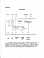
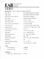
EAB 601/ADWAR CK-3 Encoded Chroma Keyer
The 601/CK-3 Encoded Chroma Keyer is
versatile, moderate cost unit .
It offers
and includes a built-in vertical-interval
601/CK-3 is used very effectively in both
a very high performance, highly
more features than other Keyers,
switcher for previewing .
The
upstream and downstream applications .
FEATURES
-
Zero Color Shift
- 'Dual Delay Lines
Four Outputs :
A, B, KEY, and Switched
Three Inputs :
A, B, and Auxilliary
Dual Comb Filters for highest resolution
Variable Highlight Key Inhibit
Joystick Keying based on Vectorscope pattern
Independent Left and Right Key edge position controls
External Drive and Genlock
Delay lines are highest quality discrete
All features are standard .
type
and
are
designed
so
that
the 601/CK-3 will pass a Tektronix 146
lumped
color bar signal with negligible distortion .
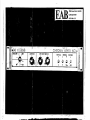
DESCRIPTION :
BLOCK DIAGRAM
VIDEO
VIDEO
AUX
SUBCARRIER
A
B
VIDEO
DRIVE
A
OUT
B
OUT
SWITCHED
OUT
CHROMA
KEYED
OUT
EXT
SYNC
DRIVE
KEY
OUT .
(OPTIONAL)
The EAB 601 / Adwar CK-3 Chroma Keyer is versatile and easy to use . It
has three video inputs and four video outputs .
It will either genlock or
accept external drive,signals .
It has no color shift . A vertical interval
switcher is built in Ebr convenience . The AUX input is useful for certain
non-critical switching Applications . An optional External Key output is
offered for use with a downstream switcher, where required (Option A) .
29411 Grove Street, Berkeley
California 94703
VIDEO
SPECIFICATIONS :
(41_5) 848-6121
EAB 601 / ADWAR CK-3 Encoded Chroma Keyer
Video Inputs
NTSC Encoded Composite/Non-composite
Video Outputs
NTSC Encoded Composite/Non-composite
External Key Output (Option A)
Monochrome Non-composite
Drive Inputs
Composite Sync and Subcarrier
Video Input Levels
1 Volt at 75 ohms
Video Output Levels
1 Volt at 75 ohms + 2 .5%
Ext . Key Output Level (Option A)
0 .7 Volt at 75 ohms
Sync Drive Level
-3 .5 Volt at 75 ohms, timed to input
Subcarrier Level
1 Volt min . at 75 ohms, timed to input
Video Output Level Matching
+ 0 .5 db
Video Flatness
+ 0 .0, -0 .2 db to 5 mhz
Video Delay
2 s . c . cycles (559 ns)
Video Delay Matching
+ 3 n . sec .
Keying Range
Hue :
Key Position Adjustment
+ 50 n . sec ., left and right edges
Connectors
BNC
Operating Temperature Range
00 C . to +55 0 C .
Input Power
105 - 130 Volts AC,
360 0
PRICES
601 Chroma Keyer
$2,500 .00
Option A (Ext Key)
$
125 .00
DISTRIBUTOR
Adwar Video,
100 Fifth Avenue,
(all outputs)
N . Y . 10011
20 Watts
APR
VIDIUM .TXT
20
'92
23 :39
P. 0 1
DOSCHIER
Tuesday, April 21, 1992 12 :34 am
VIDIUM
4/20/92
Page . 2
Jeff Schier
The Vidium "MK II" was a hybrid analog synthesizer, which
acted as a "hyper Lissajous pattern generator" . As recounted by
Larry Shaw . . . The basic Lissajous pattern, name after the French
Physicist Jules A. Lissajous consist of a circle formed
by driving an X, Y display (or oscilloscope set to XY mode) with two
''sine waves .
With the X axis "in-phase" and the Y axis "out-of-phase"
a shape is seen on the display .
If the phase shift is 90 degrees
a circle is formed, 45 degrees an ellipse, and 0 degrees a diagonal
'line .
By driving each axis with its' own oscillator, with a
- ;
jprecise phase shifting and modulation signals, elaborate shapes
'could be formed . These were expansions on the classic circle and
;figure eight pattern to form harmonically pinched doughnuts, and
Programmable waveforms
'vector textures of slowly changing form .
of sinewaves shifting to triangle waves, then square were applied
to form sinuous curves and boundaries .
A modified color television was used for the X, Y display with the
deflection yoke replaced with a new yoke driven from audio amplifiers .
The audio amp was in turn driven from the main analog waveform generator
rack . Color was added by wiring to the color "hue control", forming a
voltage controlled phase shifter, wrapping in phase 540 degrees of
the normal 360 degree hue space . Color saturation and brightness were
set by the TV's front panel controls . A special analog velocity/position
detector calculated : the square root of ( X squared plus Y squared)
deflection signals that fed the color hue shifter . A threshold detector
blanked the beam, if the X and Y settled to zero (a dot in the center of the
screen) .
The hue shifter allowed drawing of textural surfaces in smoothly
The hue shift tracked the shapas automatically .
changing colors .
The main control box consist of two 3 feet by 3 feet racks
mounted side by side . The left side contained the "voltage sequencer"
outputs with 60 multi-turn knobs, while the right side contained the
control and signal processing modules .
The main control of the synthesizer was from an analog voltage
sequencer . The "sequenced voltage source" has six controllable "steps",
each gating on 10 voltages, the voltages set by ten-turn potentiometers
'located on the left half of the rack . This six by ten matrix of voltages
were interconnected by "Pomona Stacking Banana Plug cords", to other
Commonly the sequencer was
modules located on the right half of the rack .
wired in tandem, the first module triggered the second module, etc .till the
:sixth sequencer step was triggered . An oscillator at the front end
'could start up the chain df events . Each "step" had its own time delay
',(a monostable multivibrator), and a light bulb to indicate it had triggered .
Text labels of OSC START ,'$EQ OUT - a level mimicking the state of the
sequence, and EOS (end of sequence) to wire to the next module .
Control voltages were available on colored banana jacks with RED
representing analog outputs, BLUE for analog inputs, BLACK for digital inputs
The output
(bi-level signals : on or off), and WHITE for digital outputs .
together,
multiple
outputs
signals had a "Wired-Or" property, allowing wiring
voltages
could
also
with the lower voltage being the victor . Analog
be "bare-collector" wired, the lower voltage winning out if tied together .
The "pattern generator side was built to form the basic sinewave and
phase shifted sinewaves . The modules consisted of oscillator frequency
sources, and processing modules . Multiple oscillators were present,
APR
VIDIUMMT
20
'92
23 :40
DOSCHIER
Tuesday, April 21, 1992 12 :34 am
P . 02
Page .Z
generator . The allowed voltage
including a voltage controlled function as a sync input . The output generated
control of frequency and phase as well square, sawtooth and sine . A digital
a collection of waveforms : triangle,
triggered indicator "logic out"
version of a "trigger out" and a waveformelaborate
version was proposed
are available on separate jacks . A more shape, the input voltage would shift the
to allow a voltage control of waveform
to square .
output waveform from sine through triangle
generator . A trigger pulse
envelope
Another signal source was an
"ENV STOP" turned off the pulse .
"ENV START" started a pulse output, and
voltage controlled, and digital
The rise/fall time of this pulse wastriggered
. The envelope pulse would
outputs indicated the envelope had
.
smoothly qualify the
later be combined with the main oscillators to
underlying waveform .
generation is the need
Closely tied to the idea of Lissajous pattern
wave signal . A modified filter
for controlled phase shift of the sine
lKHZ was constructed,
circuit with an operating frequency around
control input progressively
.
The
with inverting and non-inverting inputs in response to the control voltage .
shifted the phase of the input signals Voltage Controlled DC coupled Amplifier
For processing of waveforms a
with a summing input stage .
is present acting as a two quadrant multiplier,
while the voltage
The amplifier summed multiple inputs together,
and sent them to output .
control input, attenuated the summed result
generator, the sequencer voltage
The control could come from the envelope
= (In_1 + In-2) * Control
or the oscillator waveform . Output multiplier
with two sets of inputs, an
A precision Four quadrant
polarities were used to modulate
A and B with a inverting and non-inverting
Output = (IN Al - In A2) * (In B1 - In B2)
the oscillator waveforms .
and inverting of input
This four quadrants allowed both attenuation
waveforms .
summing AMPs,
The combination of the Voltage controlled
shifters allowed multiple
'ith the Four quadrant multipliers, and phase
to be combined
,scillators, envelopes and knob controlled voltages
were closely
shifts
hue
.Lnto curious patterns of X and Y signals . The
the unique
forming
linked to the pattern drawn by the X and Y waveforms,
interlocked VIDIUM Lissajous surfaces .
ELECTRONIC ASSOCIATES OF BERKELEY
1624 HARMON ST, BERKELEY, CALIF. S47 O 3
[415) 654- 1756
E~,B VIDEOIi.13._ I
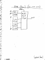
The EAB Videolab I is a video system composed of a matrix switches,
genlock, key/matte/wipe generator, and four level colorizes.
utilizes voltage control for extreme operational
The system
flexibility .
VILEOLt:B -I "YSTEM ELL:RtEhTS
1.
Wtrix
switches/genlock
- 6 inouts, 6 outputs, completely DC restored
- ;provides sync anc hover for 3 Sony ;)ortFneck cameras by means of
genlock
- 36 light emitting diodes on front panel rrovide readout of channel
selection
- channel :electing; mrnually or by voltage control with
pGtching
2.
front panel
hey/Matte generator
- utilizes function generator*3 locked to YDrizontal End vertical
scan :rates
- utilizes p~tchinqof cont-ol Eign ls betveen comp rctor
Lnd
logic elements .
- al .lovs for a virtually unlimited variety o'' k( ;i, mattes and wipes by
naea.n ;: of irterrnal or external nnculL tion of control signals .
- ;~rovic es svitc~.,inL !of-!.c levels for 6x6 m.trix
3.
Colorizer
-
iiv ic ei;
grt-y iZc<<le into Four b+_ nd .,
- provides for
each bend
- ,
is eo
cohtlol
.
imE ge s can be
of Fue,
~E
S,:a.urEtio ;:, Gray, and video level witl~ir.
t;u, into L.ra;;; band
F-11 furcTions cperj ted both' by controls on front panel and by
voltage control
- soft ke ;, voce .
professional quelitY and are supplied in
EAF VID151M modules are
rack mount cabinet :: .
The price d? the VIDIOUB I in f2950 .
delivery time
are 113 down anc net on delivery Lnd the
receipt of order unless otherwise arranged .
For in for matioa-&bout _oux, products call LAP :
1624 `:Unman St .
harkeley, CA
~,--'54-1796
94703
Terms required
is 60 days from
\j loEOIIAa
Gas
contaxt
cAm"I
REV 9-23-15
6fts.,
RI
9
/8*
11OL&
SkINXIOX
3xdr,
*h. 14OLC , ~e O.D .
Fu-,0&p7oj
0?1 cc 16A .
pA OWMAS
K,4
mynomma
wn. A"=
W6-r
O
1
8
CmtyrV(,
' S M. 0
rcjt
c,.&w.%t e a
$1,IME
EAB
6
VIDEOLAB
vjt-Ac KEY
I
A
4
I- AU ZACktCI%C)-Z CADDSJA lb 'm r-(.AXTlCN
N&DULE= F3
eL
MATXkK
6
e) (Y) Qv)
0
'D r
C
c)
-)
'.!NEAR
KS-el*:fv
Co ,- oC,
! -Z FR
(Y)
@)
0
60
0
u @
0
0
W@
0
O
0
'C
0
cc)
0
0
0
0
0
0
0
0
.i) r
u,
'o
0
0
0
@
@) @ @
K2
KI
c)
COD
t
_
~
"
@@
~ NUE
15) ON it)
43@
_,/
~
~~
~~
a
s
~t(cj
zi
L
~
05) T (500
KC"
+1
Q)
0
conows
--- %0
C)
u
6Cj
-
(5)
0
C.
EFFECTS AMP
+
VID
~"(-VUT
c
0
LOC
By
1
0
_ . ~ ~_~~~
D) @)
5.15 - 04
w__ ~
..~
.~_,
0
U
',! I 1DE"LA1D
I MSTALL .7ckT = C3 h%1
The EAD V .itdec?lab i :, uisc.+al ..ry
installed
b'::: EAB
personnel .
If difficulties arise
ti?c?
~;f
.in,
installation
yyour
unit,
call
EAS
is
Berkeley, Ca . a t
415-848-6121 .
requests
that
our
customers
not make unauthorized
adjustments
to the internal circuitry of
Vidpolaby, as it voids the
i r7
t.
GEPJEFiAiL
I IVFC]FZMAiT I "h!
POWER CONNECTONS :
at input power
The EAB
Videolab consumes
250 Watts
Maximum
is
the
customer's
voltages
of
110v-130v
a.c.,50-60
Herz.
It
responsibility to provide for Mains stabilizing within these limits .
The Videolab is powered by eight regulated power supplies . These
supplies are located in
the A module. The
Rower connection to the B
cable connecting
the two
module is made
by means
of the multi-pin
modules .
SIGNAL CONNECTIONS :
Videolab must be
made to the
All external connections
to the
rear panel. The Videolab accepts up
to six standard video signals at
inputs 1-6, and
outputs' -three composite outputs at
the connectors
marked "1","2", and "MAIN". If the videolab is to be used in the genlock
the sync and burst
mode, the video input to channel
1 must contain
components.
On some models, RGB outputs are provided on the rear panel from
the colorizes section . These outputs are 1-volt, 75 ohm non-composite,
without burst.
Signal Connections to the front panels of the modules are to be
made only to other - Videolab modules and only with the EAB patchcords
provided . A
description of
patching techniques is found in the EAB
Videolab Users Manual,, provided with each unit .
SYNC AND TIMING CONNECTIONS:
External Sync and
Subcarrier inputs are
available on
panel of
the unit
and are
automatically
activated when
these inputs are
utilized, the sync
and burst components
input signals is ignored . A 360 degree phase shift control is
for Subcarrier phasing.
the
rear
driven. If
of all six
provided
SYNC AND TIMING CONNECTIONS (CONT .);
Six genlock drive
outputs are
provided for the
convenience of
The Videolab user. These are ; "HD" (horiz. drive), "CS" (comp . sync), "VD"
(vent. drive), "CD" (composite blanking), "SC" (subcarrier drive), and "BF"
(burst flag). All are standard levels.
INITIAL
TEE3T
If desired,
the
user
may
verify
operation of
his Videolab.
Although the
flexibliity
of
the
Videolab
permits
many
modes
of
operation, the following simple steps will allow the user to verify its
basic operation:
1) Connect
a suitable
composite or
channel 1 on the rear panel.
non
composite video
signal to
2) Connect external sync and subcarrier drive signals .
3) Connect a Color monitor to the "Main" output .
4) Refer to the Videolab User's Manual. A number of simple effects may
be done with a single channel .
Apr 12,
1986
TO ALL VIDEOLAB SERIES 2 OWNERS :
TMPOR.TANT
NGTTCE!
Some EAB Videolab series 2 A/B Modules have power supplies that
may lose
regulation under
certain conditions
of ambient
temperature and AC line voltage .
The symptom is the appearance
of horizontal bands in the picture and unstable operation .
Repair of this condition is very simple, and we reccomend that
all all owners of Series 2 videolabs have this simple "fix" done .
EAB will do it for you at no charge, or you may have it done by a
qualified technician .
Please be
careful and
follow the
procedure : _a mistake can result in damage to the instrument
.PROCEDURE
1 .Disconnect all A .C .
power by unplugging the
"A" module .
Disconnect the "B" module and set it aside .
You will work on the
"A" Module only .
2 . Remove the "A" Module top and remove the five screws holding
the "A" Module back panel in place .
Gently allow the "A" Module
back panel to pivot back on its lower edge so that it is laying
on the bench .
3 . At the lower left of the rear panel is the power transformer .
on the left hand side of the power transformer
(the primary
side), the terminals are marked with the numbers 1 through 7 .
Remove (unsolder) all wires from these terminals, including any
jumpers .
Do not disturb the secondary connections, 8 through 11 .
4 . You will now have two free wires coming from the rear panel .
One wire comes directly -- from the A .C . cord,
and the other comes
from the fuse .
Solder these two free wires to terminals 1 an
_2
of the transformer primary .
5 . To double-check your work, you can measure the unregulated
D .C . Voltage at the transformer secondary before reassembling the
module .
To do this,
first locate the small terminal strip
directly to the left ~ of the horizontal slot cut in the back
panel .
Plug the "A" module into the A .C . Line (do not reconnect
the "B" module .
Uting a DC voltmeter, measure the upper terminal
on this terminal strip with respect to the rear panel (ground) .
This reading should', lie between +18 and +21 volts .
Unplug the
module .
If your ripadings were not correct, call the number
listed below before going any further .
6 . Reassemble the "A" Module .
The entire Videolab is now ready
for use .
If you wish further assistance, please call :
E A B VTDEO
William Hearn, R .P .E .E .
415-848-6121
2940 M .L . King, jr . Way, Berkeley,Ca 94703 .
~
~qx6q
b44,
K't-
;ce-
v
O
ELECTRONIC ASSOCIATES OF BERKELEY
ELECTRONIC DESIGN AND DEVELOPMENT
2940 GROVE ST., BERKELEY, CALIF . 94703 415848-6121
HOW TO USE THE -601 REYER
1 .
INPUT CONNECTIONS
A.
Connect the main camera to input "A" .
If this signal is
composite video and genlock operation is desired, the
"EXT DRIVE" switches are set "up" .
B.
Connect the background video to the "B" input .
This image
will appear in the "keyed in" areas of the main image .
C.
An auxilliary image from another source which is vertically synchronized may be connected to the "AUX" input .
This image may be switched by means of the front panel
switcher controls .
This input is not used in studio
applications and is offered as an accessory feature .
D.
2.
External sync and subcarrier signals may be connected .
If your Leyer does not have the "EXT SC PHASE TRIM"
option, then an external phase shifter will be required .
OUTPUT CONNECTIONS
A.
The "All, "B", "A/B'+, and "SWITCHED" outputs may all be
connected to the inputs of a master switcher, or to a
video syAthesizer such as the EAB Module E .
B.
The 601 may,: . act as its own switcher .
The "SWITCHED"
output offers a choice of both original images, the
"keyed" image, and a fourth (auxilliary) image .
HOW TO USE THE 601 KEYER (cont,)
3.
IMAGE QUALITY
It is vitally important for acceptable keying that the
601 receive a good quality image at the "A" input, The 601
incorporates advanced circuitry, including both horizontal
and vertical comb filtering, and will give good results on
a variety of sources .
A.
Many video sources produce video with chroma far below
Off-air and tape sources often suffer from
NTSC levels .
this defect .
B.
All 601 Chroma Keyers are set up using a standard NTSC
color source .(Tektronix 146) . The minimum level of
chroma for good quality keying is set to be 30% of the
burst amplitude, or about 12 IRE units .
C.
Blue backgrounds will often not produce the minimum
amount of signal for chroma keying unless the material
is carefully chosen . Pale blue backgrounds, for example,
are extremely inefficignt . A well lit, strongly saturated background gives best results . Use of a waveform
monitor or EAB 800 Vectorscope is suggested .
D,
The 601 jnay be readjusted to key at lower than standard
levels, although the key quality may suffer . Contact
EAB for details .
HOW TO USE THE 601 KEYER (cont .)
4.
OPERATION OF CHROMA KEYER CONTROLS
A.
Start with
1.
Chroma Joystick set at center
2 . Luminance control counter-clockwise
Key edge position controls set at "5"
3.
4.
Monitor observing A/B output .
B.
Using the joystick, locate the correct angle and minimum
displacement of the joystick to produce the required key .
C.
Advance the luminance control to inhibit highlight keying .
D.
Adjust key edge position to give best left and right key
edges .
E.
Readjust controls as necessary .
601 Encoded C h ro ma Keye r
1 .0 . and Controls
sa.
NaO rNPOTs
OPTIOMAL:
VIDEO INPUTS
A : FOREGROUND
R : BACKGROUND
AUX :
TAPS OR OTHER
ALL 75 ORM T1RMMTED
EXTERNAL SUBCARRIER DRIVE INPUT
ACCEPTS EXTERNAL 3 .58shs
VIDEO OUTPUTS
A:
FOREGROUND (DELAYED)
H:
BACKGROUND (DILATED)
A/B :
EXTERNAL SYNO DRIVE INPUT
ACCEPTS 000?OSITE SYNC DRIVE
ZED VIDEO (DELAYED)
SWITCHED:
l, I, A/B, AUX .
,LIL 75 OEM .
ECEM / EMT . VIM SIRTCBE3
VERTICAL INTERVAL, SV ITCFD;R
SETS COLOR
OF CHROMA KEY
SELECTS BETWEEN A, H, AUX,
AND EXTED VIDEO . VIDEO
APPEARS OB SWITCHED OUTPUT .
MATCHES STANDARD
N T S C VECTORSCOPE
YET POSIT ION
7,U)IIEAECE LOCIOOT
SITS PSRRMRSIBLE RANGE
OF BRIGHTNESS POR
CHROMA KEY
ImEP'~TLY ADJUSTS
LEFT AND RIGHT EDGES
OF CHROMA KEY .
THR VASULKAS, INC .
100 ROUTE 6
SANTA FE, NEW MEXICO 87501
TEL . (505) 471-7181/FAX . (505) 473-0614
March 31, 1992
Steve Anderson
1801 East Cotati
Sonoma State University
Rohnert Park, CA 94928
Bill Hearn
2940 Martin Luther King Way
Berkeley, CA 94703
Dear Steven Anderson and Bill Hearn,
We want to thank you for considering our request to borrow
the VIDIUM for the exhibition that we are curating for the ARS
ELECTRONICA Festival in Linz, Austria .
I am sending a copy of a
letter that confirms the Austrians' intention to return the
instruments after the exhibition . We are writing to both of you
concerning this loan . Based upon recent telephone conversations
it is our understanding that the VIDIUM is the property of Bill
Hearn that has been on extended loan to Sonoma State University .
Woody is planning a trip to the Bay Area Monday, April 13 and
Tuesday, April 14 regarding the documentation, restoration and
preparation of the instrument for exhibition . David Muller of
the University of Iowa_i_s the technician working on this project .
David will be preparing all of the equipment for the exhibition
and be on site in Germany for the installation and during the
exhibition, as will the Vasulkas . The Vasulkas and David Muller
will oversee all handling of the equipment . Although we cannot
offer you a fee for the installation we can offer Woody and
David's expertise and, services, as well as inclusion in this
international festival, with a full color catalogue .
In addition to highly skilled technical restoration, we are
offering very personal shipping attention .
As I mentioned,
Woody's nephew, Pav~el Skryja, will meet Woody in San Francisco
with a truck, and drive the instrument to Iowa City . We hope our
proposed dates will not be inconvenient for you . The Austrians
are picking up all the instruments and additional equipment in
Iowa City on May 4th .
However, in addition to confirming the loan, I also need
basic information for our insurance and packing plans approximate size, weight and an insurance value .
For your
convenience, I have enclosed a packing sheet of the preliminary
Wilson to Anderson, and Hearn 3/31/92, page 2 of 2
information I was given by telephone and have included suggested
Insurance Replacement Values . Please review and correct - if
As I have
necessary - then return to us by mail or fax .
indicated above, ARS BLBCTRONICA has promised to return the
VIDIUM soon after the end of the exhibition .
Please note that I need two different Insurance Replacement
Values . For shipment within the U .S ., and for the shipment to
Austria after David Muller has completely reviewed the
instrument, and restored it . As a certified appraiser with the
American Society of Appraiser, n Fine Arts, it is my opinion
that for shipment to Austria V~IUM should be valued at a higher
rate based upon the following characteristics - full restoration,
inclusion in a highly regarded international festival, and
documentation in the museum exhibition catalogue .
Please be assured that from our date of pick-up until May 4,
VIDIUM will be insured on the Vasulkas, Inc . policy, Charter
Insurance - when we receive an apposite amount from you .
Also enclosed is a more narrative description of the
exhibition that we completed recently, to give you a little
clearer idea of the exhibition .
We look forward to hearing from you .
Regards,
MaLin Wilson
Coordinator
SONOMA STATE UNIVERSITY
1801 East Cotatl Avenue
Rohnert Park, California94928
Department of Physics and Astronomy
707 684-2119
4/8/92
The Vasulkas Inc.
100 Route 6
Santa Fe, NM 87501
Mr. MaLin Wilson,
of the VIDIUM for the ARS
Thank you for the letter describing the terms of the loan
than the ones given by Mr.
ELECTRONICA exhibition . I have somewhat different dimensions
Hearn for the VIDIUM ;
Weight
De,pth
Width
Height
est. #80
10"
72"
21 (18" with attached base board)
beholder' . As an appraiser, you are
The IRV / IRV* values are somewhat "in the eye of the
the expert in this regard .
channels that I have used. Some technical
The unit is functioning, at least the four or five
grounding and polarity and so on when,
"-Jknowledge is required . I would pay attention to the
to a plywood base that is noted in the
adapting the power transformer . The unit is attached
if it were painted and had legs attached
depth dimension . This base could function as a stand
see enclosed photograph .
to it. It is presently sitting on a lab bench . Please
10 year catalog . We are a group of
I have taken the liberty of including_ the Laser Affiliates'
art performances and holography
laser performance artists that have produced visual
videotape compiled of performance
exhibitions in the Bay Area for some time . We also have a
events. If you are interested, I can
segments that captures more of the kinetic nature of these
made devices very similar to the
send a copy. In the development of theseevents I have
a computer generated animation system
VIDIUM for generating laser graphics . We also have
not depicted in the catalog.,
March 28. I am excited that other people
I will look forward to meeting Pavel and Woody on
will be able to enjoy this unique instrument .
Steve Anderson
Equipment Tech . III
Sonoma State U., Physics & Astronomy Dept.
The California State University
05/29/92
15 :25
'8`408 432 9226
CHIPS GRAPHICS
THE VASULKAS,INC
Chips and Technologies, Inc.
FACSIMILE TRANSMITTAL
FROM
THE MEDIA GROUP
GRAPHICS . MULTIMEDIA, ACCELERATORS
s ~z~~g t
DATE :
'P
TO :
vksvL. L4rr
COMPANY :
.4 0' UM
V,
SUBJECT :
FROM :
`
J
D
cf 7 '3
--
FAX :
4
0
SC H/CA-
CC :
TOTAL NUMBER OF PAGES (INCLUDING COVER SHEET) :
COMMENTS :
.~'ME
v k'
ItS
t~
I-+
VIE
o~
f
i't'~S
Yo~,T~sf
c
./T
r
re
TS
its* ILL , Co\.Lif
roR~
T4cf
T14
c c. T
T~
owPv
J~a~t#% , c
^!
S f AvEN~E~
T d 6 E TH f
y- i r r
.
E S
E _
T
e AQ NCEjeo ff.
Ik
T-4
c.~-i'
ro
S T 4- 00
IF YOU 00 NOT RECEIVE ALL PAGES, CALL BACK AS SOON AS POSSIBLE
PHONE :
FAX :
408 434-0600 (EXT . 5545)
408 432-9226
Chips and Techra>logies, Inc.
3050 Zanker Road,
San Jose, CA 93134
~2 ~,
srArcE'_
00
(408) 434 -OGW