1
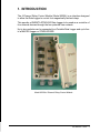
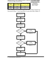
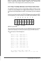
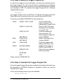
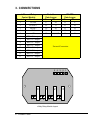
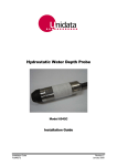
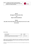
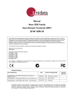
Manual – 4 Channel Relay Control Module – Model 6525
Manual
4 Channel Relay Control Module
Model 6525
Revision History
File name / Revision
Date
Authors
Previous version BX
2004
RS/ JH
Unidata Manual - 6525 4 Channel Relay Control Module User Manual Issue 2.0
2007
AB/CB/JH/MS/KC
Copyright © Unidata Pty Ltd 2000-2008. All rights reserved. No part of this publication may be reproduced, transmitted,
transcribed, stored in a retrieval system, or translated into any spoken or computer language, in any form or by any means.
Electronic, mechanical, magnetic, optical, chemical, manual or otherwise, without prior written permission of Unidata Pty Ltd 40
Ladner St, O’Connor Western Australia 6163.
Unidata Manual - 6525 4 Channel Relay Control Module User Manual Issue 2.0
Table of Contents
1.
INTRODUCTION . . . . . . . . . . . . . . . . . . . . . . . . . . . . . . 1
2.
CONTROLLING THE RELAYS . . . . . . . . . . . . . . . . . . 2
2.1.
The High Speed Bi-Directional Serial Port . . . . . . . . . . . . . 2
2.2.
2.2.1.
2.2.2.
2.2.3.
2.2.4.
2.2.5.
2.2.6.
Programming the Relays . . . . . . . . . . . . . . . . . . . . . . . . . . . 3
Step 1: Create and Save a Scheme . . . . . . . . . . . . . . . . . . . . 3
Step 2: Decide When to Open and Close the Relays . . . . . . . 3
Step 3: Identify Addresses and Choose Instructions . . . . . . . 5
Step 4: Modify the Logger Program file . . . . . . . . . . . . . . . . . . 6
Step 5: Assemble the Logger Program File . . . . . . . . . . . . . . 6
Step 6: Load the Scheme into the Logger . . . . . . . . . . . . . . . . 7
2.3
Serial Communications Instructions . . . . . . . . . . . . . . . . . . 7
3.
CONNECTIONS . . . . . . . . . . . . . . . . . . . . . . . . . . . . . . 8
4.
TEST PROGRAM . . . . . . . . . . . . . . . . . . . . . . . . . . . . . 9
5.
SPECIFICATIONS . . . . . . . . . . . . . . . . . . . . . . . . . . . 10
Contents – i
ii – Contents
1. INTRODUCTION
The 4-Channel Relay Control Module (Model 6525A) is an interface designed
to allow the Data Logger to control four magnetically latched relays.
This permits a UNIDATA STARLOG Data Logger to be used as a controller of
four external devices through the four potential free contacts.
Up to two modules can be connected to a Portable Data Logger and up to four
to a MACRO Logger or STARLOGGER.
Model 6525A 4-Channel Relay Control Module
INTRODUCTION – 1
2. CONTROLLING THE RELAYS
The 4 Channel Relay Control Module is controlled by the Data Logger. The
Logger provides power to the module as well as controlling the relays.
The scan synchronised power source – offered by both the Portable and
MACRO Data Logger – provides power to the module. (See Connections,
section 3.) This source switches on with every scan.
Each relay is controlled by command from the Data Logger using one of the
High Speed Bi-Directional Serial Ports. The commands sent from Logger to
Module tell the Module which relay(s) to activate. These commands are first
interpreted by the module, then implemented when the Logger sends a pulse to
the Module.
2.1. The High Speed Bi-Directional Serial Port
The High Speed Serial Port consists of a DATA line and a CLOCK line. The
CLOCK enables commands sent on the serial DATA line to be interpreted
correctly by the module. Each logger scan, the Serial Ports are read. The Sync
signal (Pin 13 of the STARLOGGER, for instance) is used to indicate to the
remote equipment that a logger read scan is about to begin. This signal is
usually used to load the serial shift register(s) in the remote equipment in
preparation of being read.
The STARLOGGER and MACRO Data Logger offer two bi-directional serial
data ports, DATA 1 and DATA 0.
The Portable Data Logger provides one bi-directional data port, DATA 1. Either
CLOCK 0 or CLOCK 1 can be used with DATA 1. The Portable Data Logger’s
DATA 0 is unsuitable because it cannot be used to send data.
The examples and explanations in this supplement assume you are using DATA
1 and CLOCK 1.
2 – CONTROLLING THE RELAYS
2.2. Programming the Relays
This section provides a simple example of how to program the relays. In some
cases, the skills of an experienced Programmer may be necessary. In summary,
the procedure of programming the module is:
1. Create and Save a Scheme.
2. Decide when you want to open and close the relays.
3. Identify which addresses in Data Logger memory will be used
and which instructions you’ll require – usually, JUMP (and its
variations), LOAD, SEROUT and PULSE. (Refer to the
STARLOG Programming supplement 6201.)
4. Use an ASCII editor to modify the Logger Program file,
SCHEME.SRC. Add the instructions in the appropriate places.
Save the file.
5. Use PDLASM to assemble the revised file.
5. Finally, load the Scheme into the Logger.
2.2.1. Step 1: Create and Save a Scheme
In this example, two of the relays on the 4-Channel Relay Control Module are
used to operate alarms when the water level of a river is either very high or very
low. A Hydrostatic Water Depth & Temperature Probe (model 6508A) connected to a Portable Data Logger is used to monitor water level in the river.
The Scheme: Every 5 seconds (scan rate) data from the probe is being sent to
a Portable Data Logger on Analog Channel 0 (a0).
Using the STARLOG Software Package create a Scheme which includes the
above details. You will also want to include when and what to log and how to
present the data, like in a report or a plot. (See the STARLOG Users Manual.)
2.2.2. Step 2: Decide When to Open and Close the Relays
The river height is usually approximately 1⁄2 metre. If it drops to 25 cm, then the
cattle will have to be moved into a paddock with a dam. On the other hand, if the
river rises to 75 cm, then the pump will have to be relocated. When the probe
measures 25 cm or less we want to trigger the LOW alarm. When the probe
reads 75 cm or higher we want to trigger the HIGH alarm.
Data from the Water Depth Probe on Analog Channel 0 is temporarily stored in
the Logger’s Hardware Register in Address 16 (the address for a0). It is this
CONTROLLING THE RELAYS – 3
reading that we will use to trigger the alarms. Therefore, the
readings
in address
* This
is a value
which
16 which will trigger the alarms are:
corresponds to actual
Label
Actual Height
As Read by Logger
*
High
75 cm
191
Low
25 cm
63
height on a scale from 0
to 255 where
0 is 0 metre and
255 is 1 metre.
In this example you will connect the High River alarm to Relay 0 and the Low
River alarm to Relay 1. You will want Relay 0 to open when data in Address 16
read water level
put
level at address 16
(= 0 - 255)
compare address 16
with upper limit
is
level > upper
limit ?
YES
activate
high river alarm
RELAY 0
NO
compare address 16
with lower limit
is
level < lower
limit ?
YES
activate
low river alarm
RELAY 1
NO
de-activate
both alarms
exit
4 – CONTROLLING THE RELAYS
reads 191 or greater. This sets off the High River Alarm. Likewise, you will want
Relay 1 to open when the data in Address 16 reads 63 or less. This sets off the
Low River alarm. A flow diagram (below) illustrates this process.
2.2.3. Step 3: Identify Addresses and Choose Instructions
You already know that you want to compare data in address 16. Now you have
to select an unused address in the Logger Hardware Register into which the
control byte for the Relay Module is written. In this example, you will use address
90.
Instructions are listed in detail in the STARLOG Programming supplement 6201.
For this application, you are most likely to use JUMP (and its variations), LOAD,
7
6
5
RL3
OFF
RL3
ON
1 = TRUE
4
RL2 RL2
OFF ON
3
2
RL1 RL1
OFF ON
1
0
RL0 RL0
OFF ON
0 = FALSE
SEROUT and PULSE.
The control data is given to the module using the SEROUT instruction and then
output to the relays by a 10 milli-second pulse using the PULSE instruction.
The control byte is of the following form:
i.e.,
Relay 0 = ON
= 0000 0001 = 1
Relay 0 = OFF = 0000 0010 = 2
Relay 1 = ON
= 0000 0100 = 4
Relay 1 = OFF = 0000 1000 = 8
Relay 2 = ON
= 0001 0000 = 16
Relay 2 = OFF = 0010 0000 = 32
Relay 3 = ON
= 0100 0000 = 64
Relay 3 = OFF = 1000 0000 = 128
eg, relays 0 and 3 OFF, 1 and 2 ON
output byte = 1001 0110 = 150 = 2 + 4 + 16 + 128
CONTROLLING THE RELAYS – 5
2.2.4. Step 4: Modify the Logger Program file
In order for the Logger to control the Relays, you will want to add a few lines to
the Logger Program file. This is the file which is generated by the Software
Package each time you Save a Scheme. It is given the Scheme Name followed
by the extension .SRC. For instance, the Logger Program file for a Scheme
called RIVER would be:
RIVER.SRC
The Logger Program file is an ASCII file. To add the lines which control the
Relay Module use a word processor which can edit and save ASCII files.
The lines you will add to RIVER.SRC for this example are:
SCAN:
JMPGE 16,#191, HIGH
JMPLE 16, #63, LOW
LOAD 90, #170
LOW:
JMP RELAY
LOAD 90, #9
JMP RELAY
LOAD 90,#6
RELAY:
MOVWW 9,#8208
HIGH:
SEROUT #1,90
(jump to HIGH if the)
(value in address 16 is)
(greater than or equal to 191)
(jump to LOW if the value)
(in address 16 is less than)
(or equal to 191)
(Load into address 90)
(the control byte 170)
(which means all relays off)
(Jump to RELAY)
(Relay 1 Off, Relay 0 On)
(Jump to RELAY)
(Load 6 into address 90)
(Relay 0 Off, Relay 1 On)
(Prepares the Logger to)
(DATA 1 and CLOCK 1)
(Send 1 byte from address)
(90 to the module)
PULSE #45
EXIT
Finally, save the RIVER.SRC file.
2.2.5. Step 5: Assemble the Logger Program File
Once the Logger Program file has been modified and saved you will want to use
the Assembler in STARLOG Software to assemble it before you load the
Scheme into a Logger.
In the current working directory, type the command:
PDLASM RIVER.SRC
6 – CONTROLLING THE RELAYS
2.2.6. Step 6: Load the Scheme into the Logger
Using the menu-driven STARLOG Software Package select Use a Scheme
from the main menu, then Choose a Scheme and finally, Program Logger
with Scheme.
Remember that if you at any time modify the Scheme using the menus, you will
need to once again add commands to the Scheme Program file and assemble
it in order to use the 4-Channel Relay Control Module.
2.3. Serial Communication Instructions
The Logger provides the following instructions for serial communications:
SERIN, SEROUT
SERIN0, SEROUT0
SERIN1, SEROUT1
all Loggers DATA0
used for DATA0 in MACRO Logger and
STARLOGGER
used for DATA1 in MACRO Logger and
STARLOGGER
SERIN x,y,z
(SERIN0 and SERIN1)
extract x bytes of serial data from the specified data line and store that data in
Block z, Locations y, y+1 ... y+x.
eg, SERIN 4,50,1
=
72,4,50,1
will cause four bytes of data to be read and stored in Block 1, Location 50 to
Block 1, Location 53 (addresses 306 - 309).
SEROUT x,y,z
(SEROUT0 and SEROUT1)
is similar to the SERIN instruction except that data is taken from Block z,
Location y etc. and output on the appropriate data line.
Another variation of the above two instructions allows the user to ’point’ to the
address where the data will come from/go to, ie y contains the address of a
pointer to the actual data area.
Further to the above instructions, it must be specified which DATA and CLOCK
lines are being used. This is done by placing particular data in addresses 8, 9
and 10.
Address 8 =
Address 9 =
Address 9 =
Address 10=
32 if CLOCK 1 is used, (A8=0 if not)
16 if DATA 1 is used,
128 if DATA 0 is used,
64 if CLOCK 0 is used, (A10=0 if not)
CONTROLLING THE RELAYS – 7
3. CONNECTIONS
4-Channel Relay
Control Module
Terminal
Function
1
PULSE
2
CLOCK 1
3
DATA 1
4
GND
5
+5V
6
RELAY 0 output
7
RELAY 0 output
8
RELAY 1 output
9
RELAY 1 output
10
RELAY 2 output
11
RELAY 2 output
12
RELAY 3 output
13
RELAY 3 output
Portable
Data Logger
Pin
Term.
17
42
22
13
10
45
23
10
13
15,16,17
MACRO
Data Logger
Pin
Term.
33
9
13
16
31
15
17
13
18
49
External Connection
5 4 3 2 1
0
6 7
1
8
9
2
10 11
3
12 13
4-Way Relay Module Layout
8 – CONNECTIONS
4. TEST PROGRAM
You can use the Test a Logger menus in STARLOG Software to check the
operation of the module. Use the PDL Information menu and the PUT and
ADDRESS commnads to enter the following data.
PDL only, not needed
for a MACRO Logger.
Address 8 : 0,16,32,0 (for DATA 1 and CLOCK 1)
Address 51 : 170
Address 384 : 8,4,1,6,76,1,50,0
Address 392 : 24,0,45,0,0,0,0,0
These numbers are 77 for a
MACRO Logger
Address 400 : 76,1,51,0,24,0,30,0
Address 408 : 0,0,0,0
Then, by putting the following at address 50, each relay can be turned on and
off, each log cycle, in turn.
Address 50 :
1 (relay 0)
4 (relay 1)
16 (relay 2)
64 (relay 3)
TEST PROGRAM – 9
5. SPECIFICATIONS
Dimensions:
Input:
Output:
Power Usage:
Relay Contact
Ratings:
10 – SPECIFICATIONS
75mm x 125mm x 80mm
programmable output control from Logger
potential free latched relay contact (DPDT)
2mA max.
240V AC @ 0.5 A max.